Bose 412568 802.11b/g and Bluetooth LE Wireless Module User Manual MANUAL AND LABELING REQUIREMENTS
Bose Corporation 802.11b/g and Bluetooth LE Wireless Module MANUAL AND LABELING REQUIREMENTS
Bose >
Manual.pdf
2.4GHz RF Modular Transceiver System
Installation manual (draft v1)
1. Description
This document describes an RF transceiver module PCB having two independent
radio transceivers. One radio complies to IEEE 802.11b/g protocols and the other to
the Bluetooth Low Energy specification. The module provided on-board power
regulation and full shielding for the radio transceivers.
2.
The module consists of 2 separate circuits :
1) A 2.4GHz Wi-Fi RF transceiver IC and two PIF etch antennas.
2) A 2.4GHz Bluetooth Low Energy transceiver IC and one PIF etch antennas.
3. Cautions:
This equipment has been tested and found to comply with the limits for a Class B digital
device, pursuant to Part 15 of the FCC Rules. These limits are designed to provide
reasonable protection against harmful interference in a residential installation. This
equipment generates uses and can radiate radio frequency energy and, if not installed
and used in accordance with the instructions, may cause harmful interference to radio
communications. However, there is no guarantee that interference will not occur in a
particular installation. If this equipment does cause harmful interference to radio or
television reception, which can be determined by turning the equipment off and on, the
user is encouraged to try to correct the interference by one of the following measures:
- Reorient or relocate the receiving antenna.
- Increase the separation between the equipment and receiver.
- Connect the equipment into an outlet on a circuit different from that
to which the receiver is connected.
- Consult the dealer or an experienced radio/TV technician for help.
This device complies with Part 15 of the FCC Rules. Operation is subject to the following
two conditions: (1) This device may not cause harmful interference, and (2) this device
must accept any interference received, including interference that may cause
undesired operation.
Any changes or modifications not expressly approved by Bose Corporation could void the
user's authority to operate this equipment.
WARNING! This module is to be installed only by Bose Corporation in its end products,
and shall not be marketed to any other party.
This RF Module has been certified for integration into products without further
certification. However, Bose Corporation is still responsible for testing its end products
for any additional compliance requirements required with this module installed (such as
digital device emissions, PC peripheral requirements, etc.).

End Product Labeling
This module is labeled with its own FCC ID and IC Certification Number. If the label is not visible
when the module is installed inside another device, then the outside of the device into which
this module is installed must also display a label referring to the enclosed module. In that case,
the final end product must be labeled in a visible area with the following:
“Contains Transmitter Module FCC ID: A94412568”
“Contains Transmitter Module IC: 3232A-412568”
or
“Contains FCC ID: A94412568”
“Contains IC: 3232A-412568”
IMPORTANT NOTE: In the event that these conditions can not be met (for certain
configurations or collocation with another transmitter), then the FCC and Industry
Canada authorizations are no longer considered valid and the FCC ID and IC
Certification Number can not be used on the final product. In that case the end
product must be re-evaluated to obtain separate FCC and Industry Canada
authorizations.
In addition, Information regarding how to install or remove this RF module or change its
RF related parameters should not be provided to the end user.
The user manual for the end product must include the following information in a
prominent location:
“To comply with FCC and Industry Canada RF radiation exposure limits for general
population/uncontrolled exposure, the antenna(s) used for this transmitter must be
installed such that a minimum separation distance of 20cm is maintained between the
radiator (antenna) and all persons at all times. In addition this transmitter must not be
collocated or operating in conjunction with any other antenna or transmitter.”
This device complies with Industry Canada licence-exempt RSS standard(s). Operation is
subject to the following two conditions: (1) this device may not cause interference, and
(2) this device must accept any interference, including interference that may cause
undesired operation of the device.
Le présent appareil est conforme aux CNR d'Industrie Canada applicables aux
appareils radio exempts de licence. L'exploitation est autorisée aux deux conditions
suivantes : (1) l'appareil ne doit pas produire de brouillage, et (2) l'utilisateur de
l'appareil doit accepter tout brouillage radioélectrique subi, même si le brouillage est
susceptible d'en compromettre le fonctionnement.
Under Industry Canada regulations, this radio transmitter may only operate using an
antenna of a type and maximum (or lesser) gain approved for the transmitter by Industry
Canada. To reduce potential radio interference to other users, the antenna type and its
gain should be so chosen that the equivalent isotropically radiated power (e.i.r.p.) is not
more than that necessary for successful communication.
Conformément à la réglementation d'Industrie Canada, le présent émetteur radio
peut fonctionner avec une antenne d'un type et d'un gain maximal (ou inférieur)
approuvé pour l'émetteur par Industrie Canada. Dans le but de réduire les risques de
brouillage radioélectrique à l'intention des autres utilisateurs, il faut choisir le type
d'antenne et son gain de sorte que la puissance isotrope rayonnée équivalente
(p.i.r.e.) ne dépasse pas l'intensité nécessaire à l'établissement d'une communication
satisfaisante.
4. Markings
4.1 This module shall be identified with the following ID numbers on the radio
shields.
FCC ID : A94412568
IC : 3232A-412568
4.2 End Product Labeling
The final end product which this module is used in must be labeled in a visible
area with the following:
"Contains FCC ID: A94412568 / IC:3232A-412568"
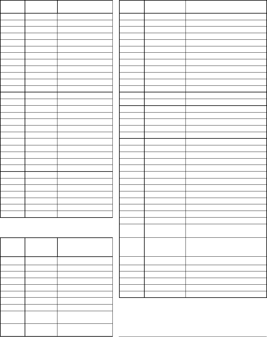
5. Connections
The following tables describe the connections to the module made via the four
connectors.
J1201
Pin #
Group
Name
Signal Name
J1203
Pin #
Group Name
Signal Name
31
Ethernet
GND
1
Audio Out
AIC3256LRET\BASE
30
Ethernet
TXP
2
Audio Out
AIC3256LOUT
29
Ethernet
TXN
3
Audio Out
AIC3256RRET
28
Ethernet
LCMT
4
Audio Out
AIC3256ROUT
27
Ethernet
RXP
5
Audio Out
EXTDACLRET
26
Ethernet
RXN
6
Audio Out
EXTDACLOUT
25
Ethernet
GND
7
Audio Out
EXTDACRRET
24
Ethernet
(+)3.3V_ET
8
Audio Out
EXTDACROUT
23
Ethernet
SPD_LED_AN
9
Audio Control
MUTEOUTN
22
Ethernet
SPD_LED_CA
10
Audio Control
AMPSTBYN
21
Ethernet
LKACT_LED_AN
11
Audio Control
AMPFAULTN
20
Ethernet
LKACT_LED_CA
12
Audio Control
AUDOUTBCLK (R1200)
19
USB
USB0_5V_FAULT_L
13
SMPS, PA sync
GND
18
USB
MICROB_DET
14
SMPS, PA sync
AUDIO_SYNC_OUT (R1208)
17
USB
MICROB_SEL
15
Monitor Inputs
IDIN
16
USB
USB0_DRVVBUS
16
Monitor Inputs
PAOFFSET1
15
USB
USB0_ID
17
Monitor Inputs
PAOFFSET2
14
USB
GND
18
Monitor Inputs
PWRMON
13
USB
USB0_DM
19
Monitor Inputs
THERMISTOR
12
USB
USB0_DP
20
Audio Power
+5VA
11
USB
GND
21
Smartspeaker
UART0_RXD/IR_IN_T
10
USB
USB0_VBUS
22
GND
GND
9
USB
USB0_VBUS
23
Smartspeaker
UART0_TXD
8
USB
GND
24
User Interface
LED0
7
AUX/TAP
AUX_LEFT
25
User Interface
LED1
6
AUX/TAP
AUX_RETURN
26
GND
GND
5
AUX/TAP
AUX_RIGHT
27
Misc
I2C0_SCL
4
AUX/TAP
GND
28
GND
GND
3
AUX/TAP
TAP_IN
29
Misc
I2C0_SDA
2
AUX/TAP
TAP_OUT
30
Misc
STATICIN
1
AUX/TAP
GND
31
Misc
BATT_CHG_EN_L
32
Misc
DC_PRESENT_L
33
Power
PGND
J1200
Pin #
Group
Name
Signal Name
34
Power
PPOS
10
Ground
GND
35
Power
PGND
9
Button
STROBE0
36
Power
PPOS
8
Button
STROBE1
37
Power
PGND
7
Button
STROBE2
38
Power
PPOS
6
Button
SWITCHIN0
39
Power
PGND
5
Button
SWITCHIN1
40
Power
PPOS
4
Button
SWITCHIN2
3
Ground
GND
2
Button
Sense
STATICIN
1
Ground
GND

J1202
Pin #
Group Name
Group Name
12
GND
GND
11
LED
LED0
10
LED
LED1
9
OLED Power
OLED_17V
8
IR_RECEIVER
UART0_RXD/IR_IN
7
Anode + Power
LED_5V
6
OLED Control
DISPCEN
5
OLED Control
DISPRESN
4
OLED Control
DISPDCN
3
OLED Control
SP1_SCLK
2
OLED Control
SPI2_DO
1
GND
GND
6. General Electrical specifications
6.1 Power supply 5.0V +/- 5%
6.2 Power consumption <5 Watts
6.3 Operational Temperature 0 ~ 45 C (non-condensing)
7. 2.4GHz BTLE RF Transceiver
The RF transceiver uses a TI CC2540 low cost, low power RF transceiver IC to drive
a 50 ohm etch antenna via a simple balun and matching network. A switched coaxial
connector is provided for test purpose to measure the output power from the IC and
balun
7.1 Electrical Specification
For a detailed description of the CC2540 and the most recent electrical
specification see the full vendor part spec SWRS084E available on TI web site:
http://www.ti.com/lit/ds/swrs084e/swrs084e.pdf
The module shall use the following settings :
7.1.1 RF Output Power : +4dBm typical (measured at J801)
7.1.2 Useable Frequency Range: 2401.67 – 2482 MHz
7.1.3 Modulation <1 Mb/sec GFSK with data
whitening
7.1.4 Channel Spacing 2 MHz
7.2 2.4GHz 802.11b/g RF Transceiver
The transceiver uses a proprietary and confidential chip set from SMSC
corporation for control and implementation of the IEEE 802.11b/g radio. A
DM870 control chip implements the transmission protocol and feeds I-Q
information to the company’s T6201C RF transceiver. For transmit, the RF path
includes a power amplifier SST12LP15A from Microchip.
The module shall use the following settings:
7.2.1 RF output power: +11dBm typical (measured at CON4)
7.2.2 Useable frequency range: 2412 – 2462MHz (Western Hemisphere)
7.2.3 Modulation: OFDM
7.2.4 Channel spacing: 5 MHz
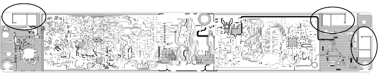
7.3 Antenna Specification
The RF module uses three Planar Inverted F etch antennas, two in switched
diversity mode for Wi-Fi and one for Bluetooth Low Energy. The PCB layout
capture below shows their relative locations. The overall board dimensions are
225mm long by 37mm wide.
BTLE antenna Wi-Fi antennas