Boston Scientific Neuromodulation PSC5210W Precision SCS System Remote Control User Manual II Physicians Lead and Extension
Boston Scientific Neuromodulation Corporation Precision SCS System Remote Control II Physicians Lead and Extension
Contents
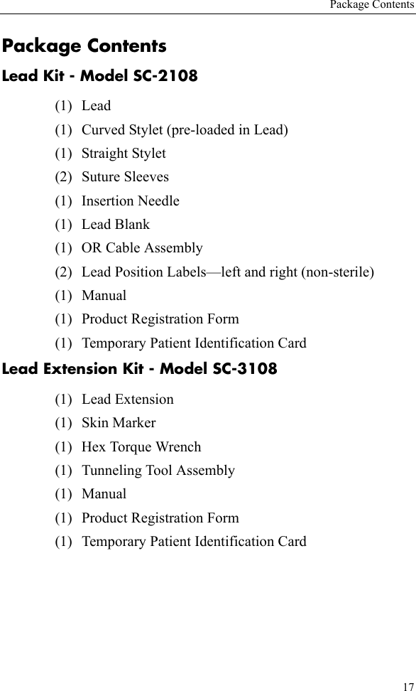
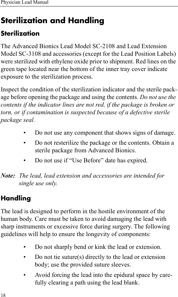
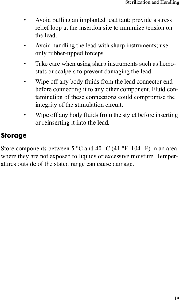
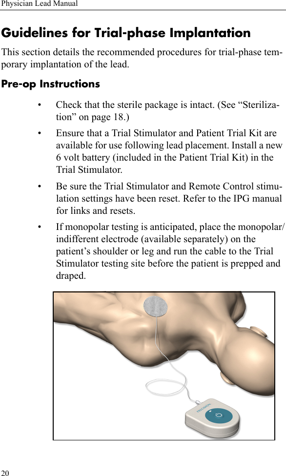
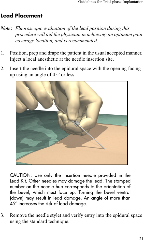
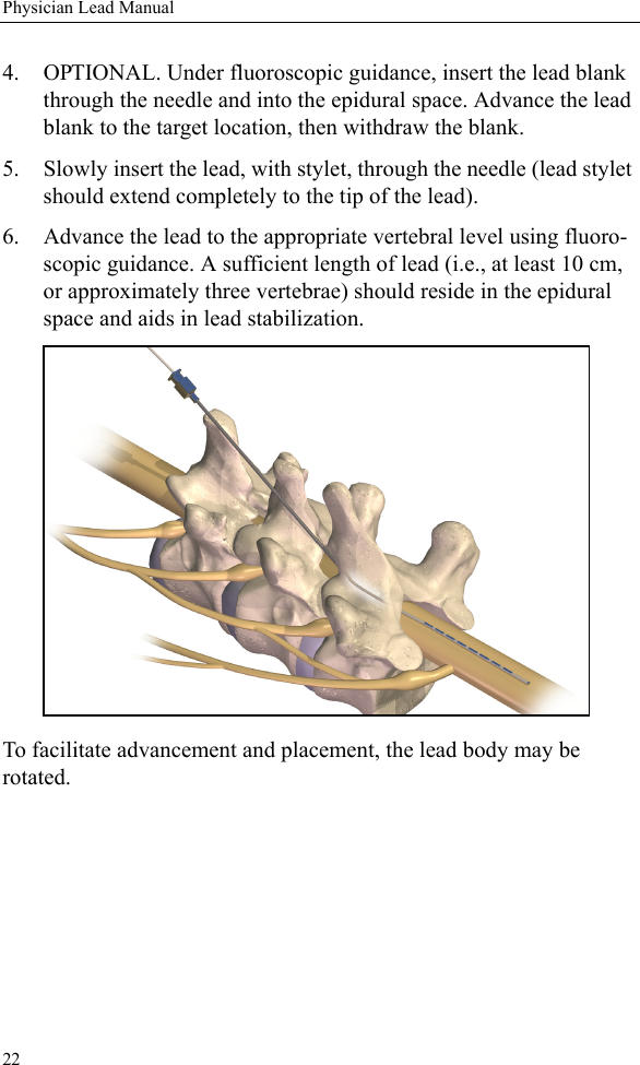
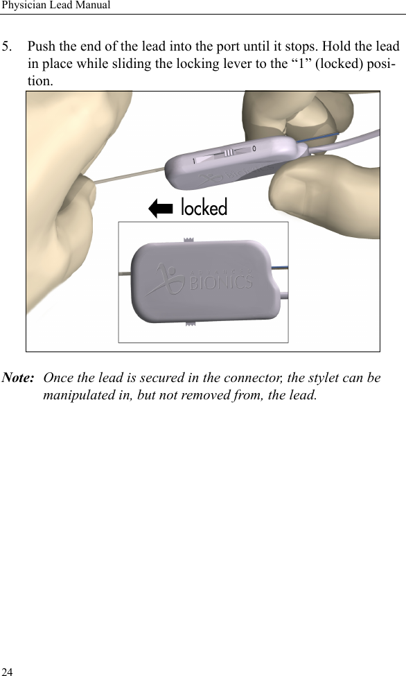
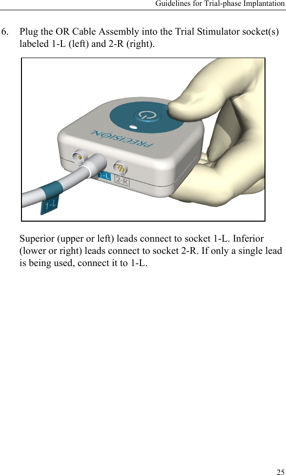
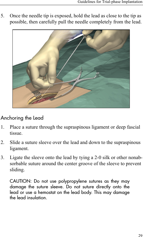
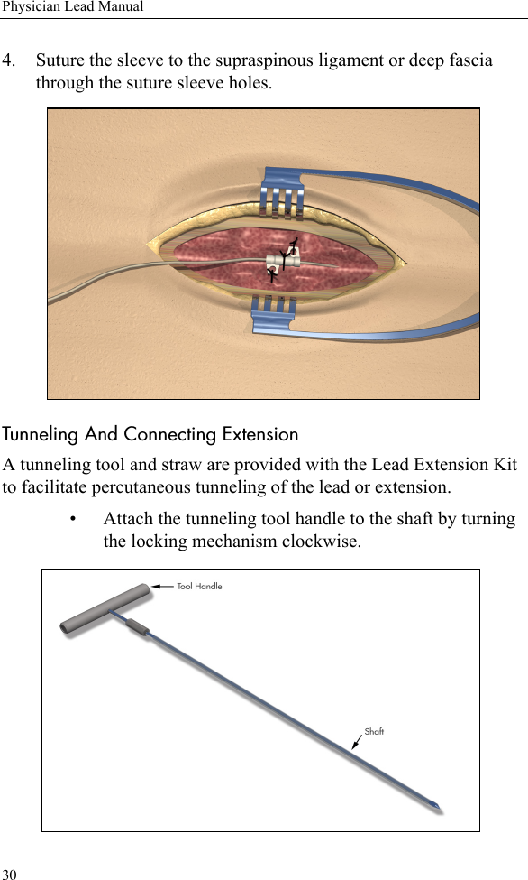
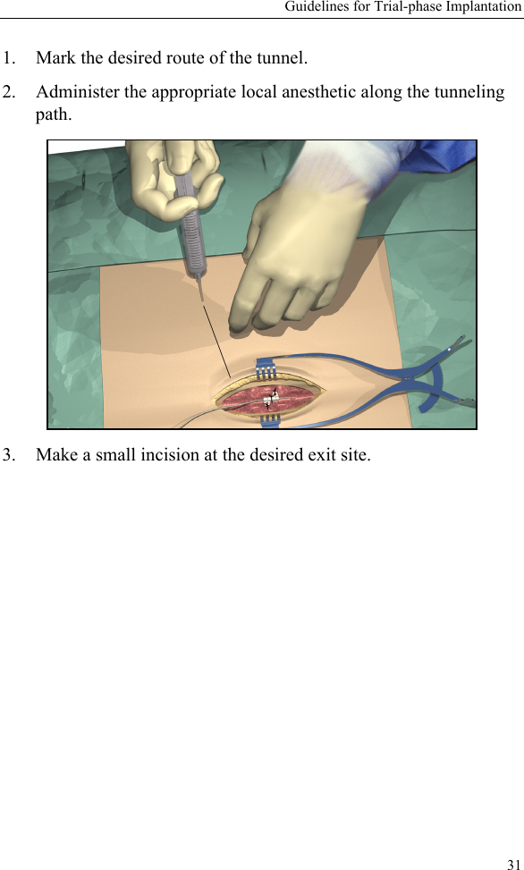
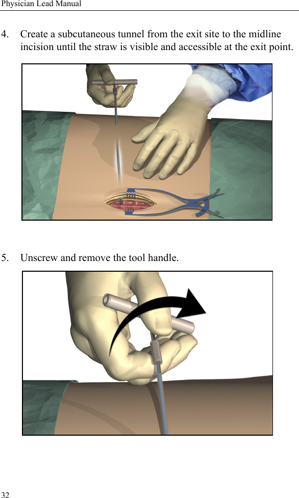
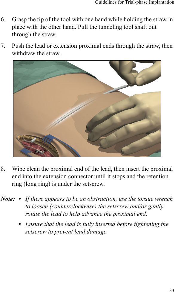
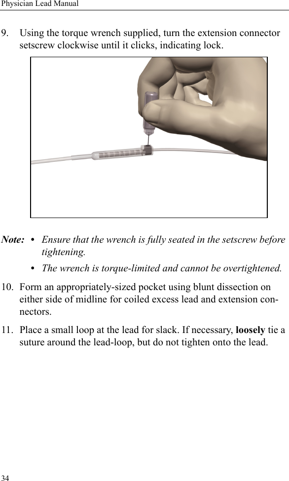
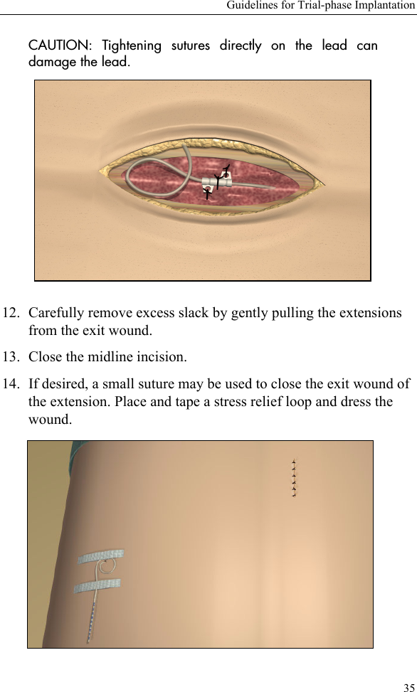
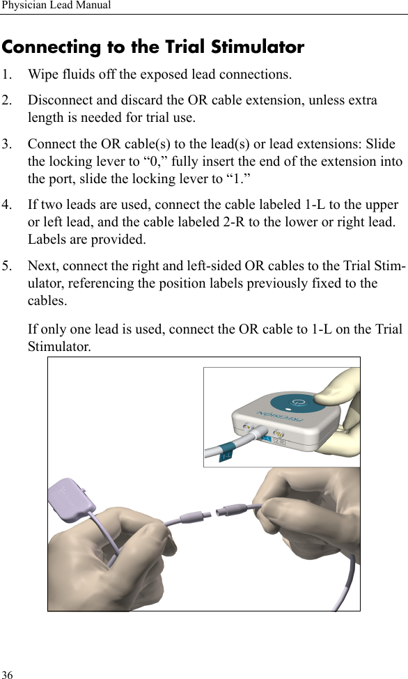
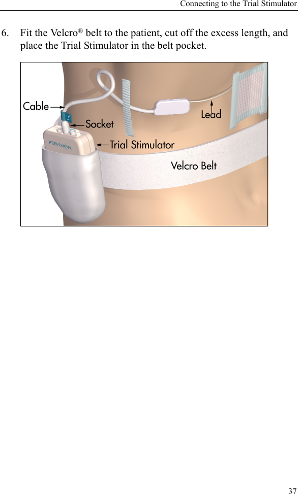
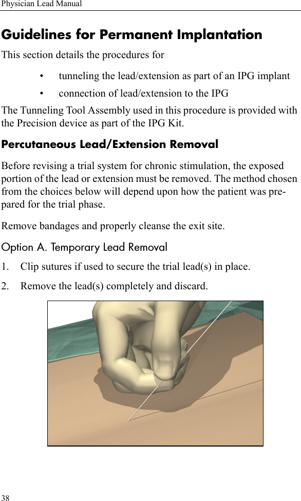
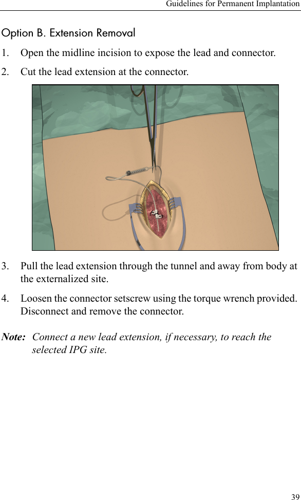
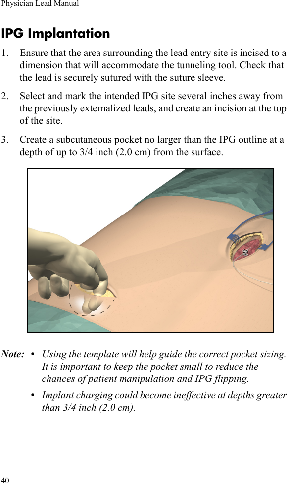
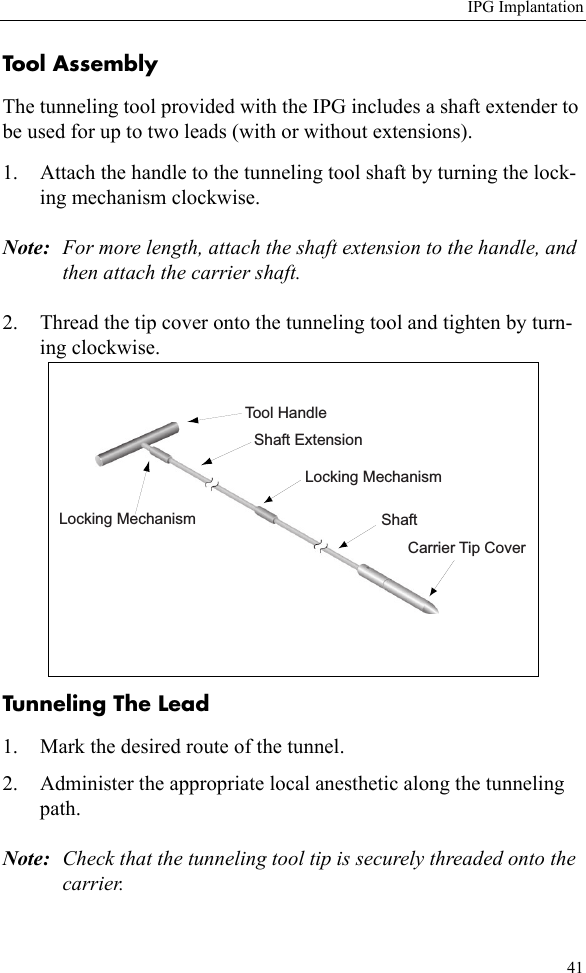
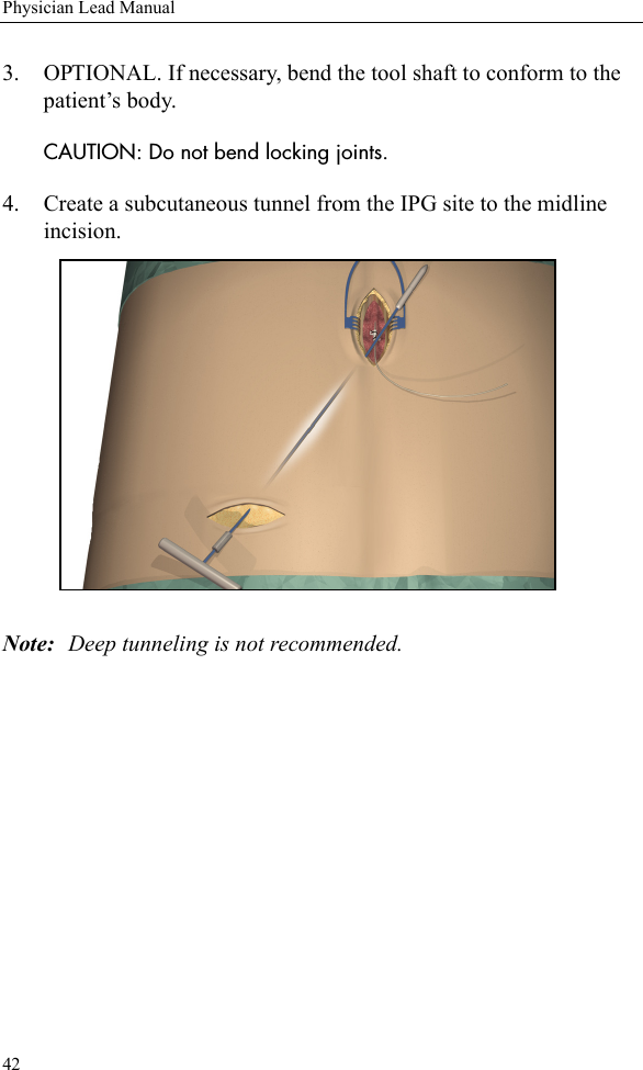
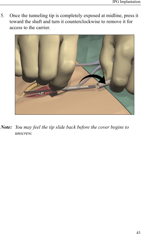
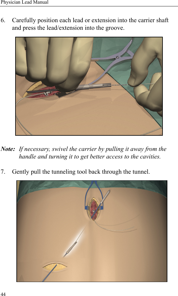
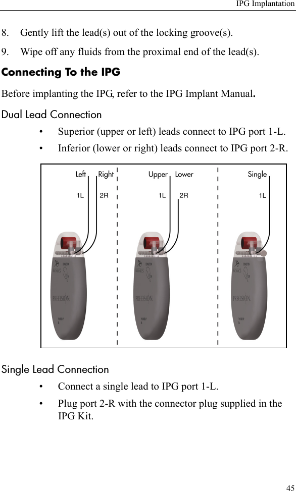
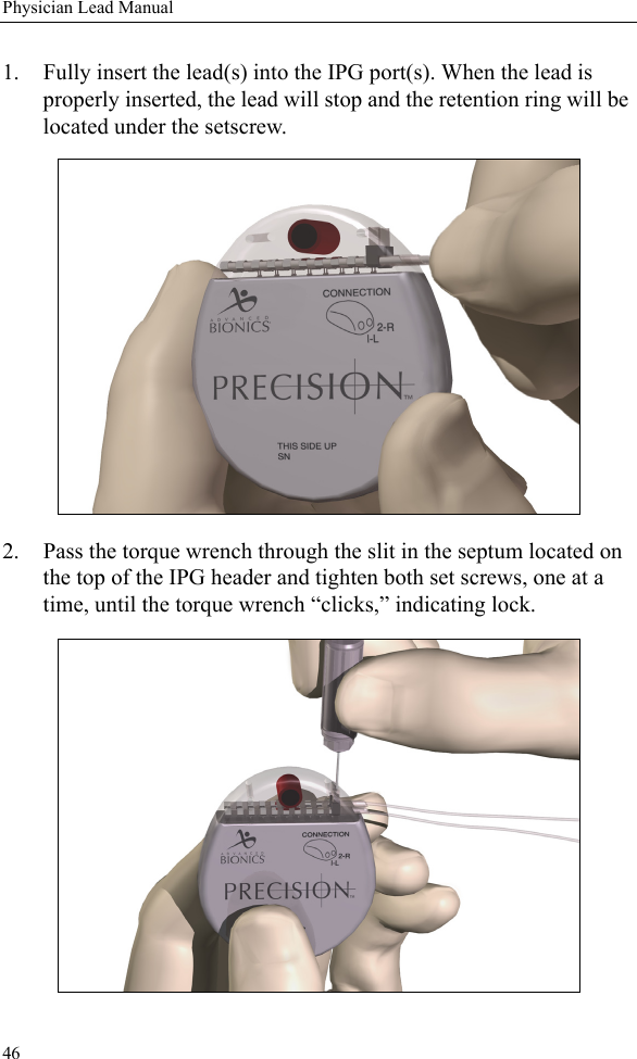
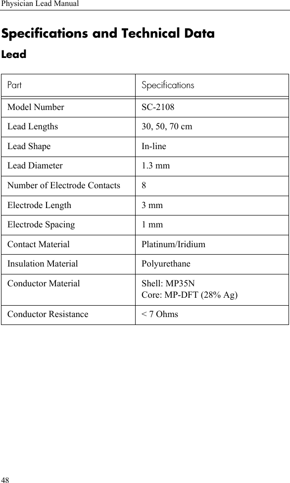
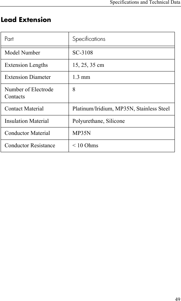
Lead manual