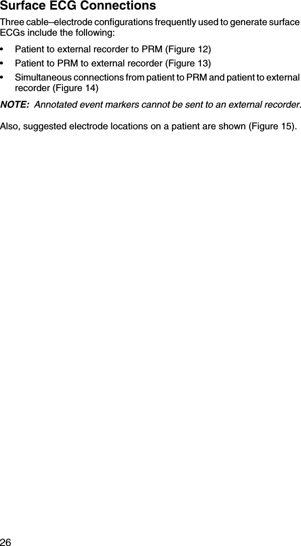
Boston Scientific CRM312005 Model 3120 User Manual Draft Literature Labeling Review
Boston Scientific Corporation Model 3120 Draft Literature Labeling Review
UserManual.wiki
>
Boston Scientific
>
CRM312005 User Manual
Users Manual
Navigation menu
Upload a User Manual
Namespaces
Wiki Guide
HTML
PDF
Info
Views
User Manual
Discussion / Help
Navigation
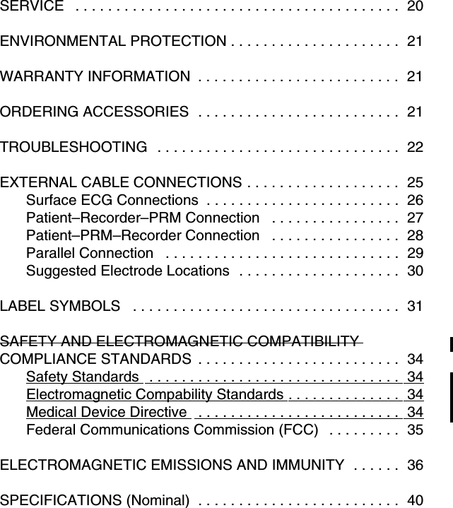
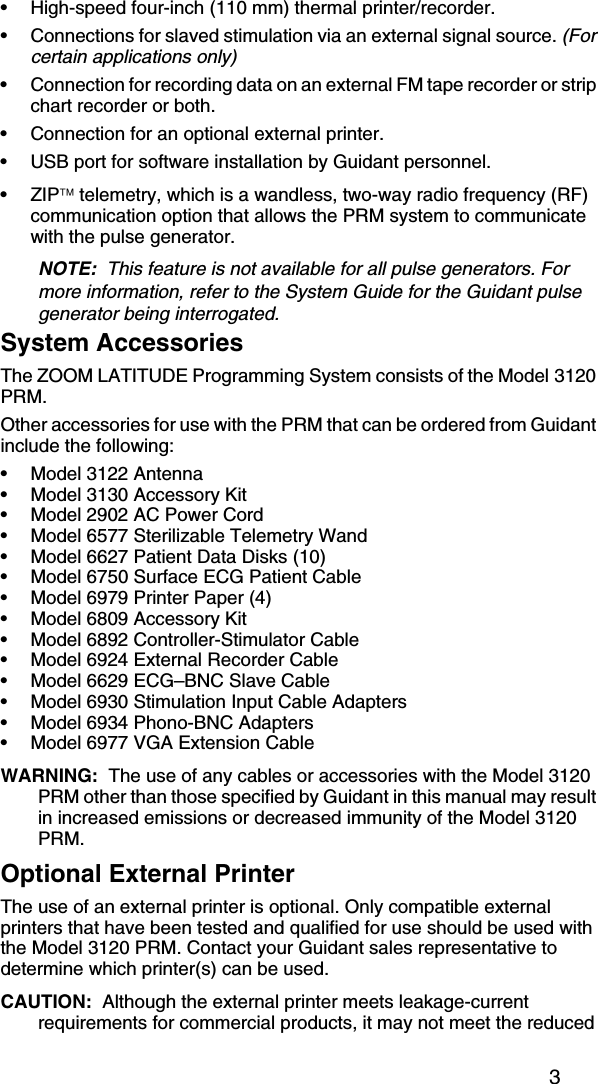
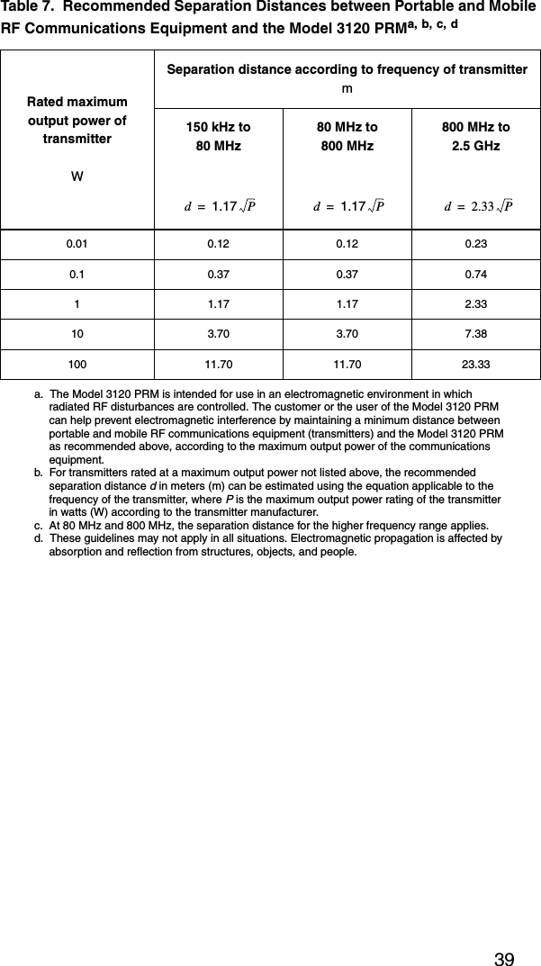
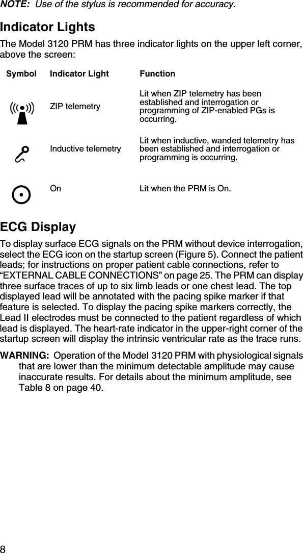
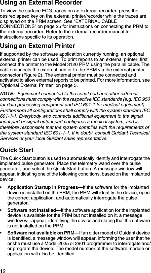
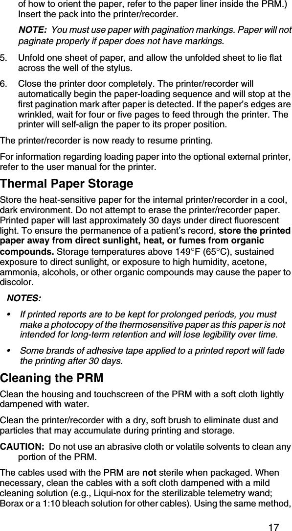
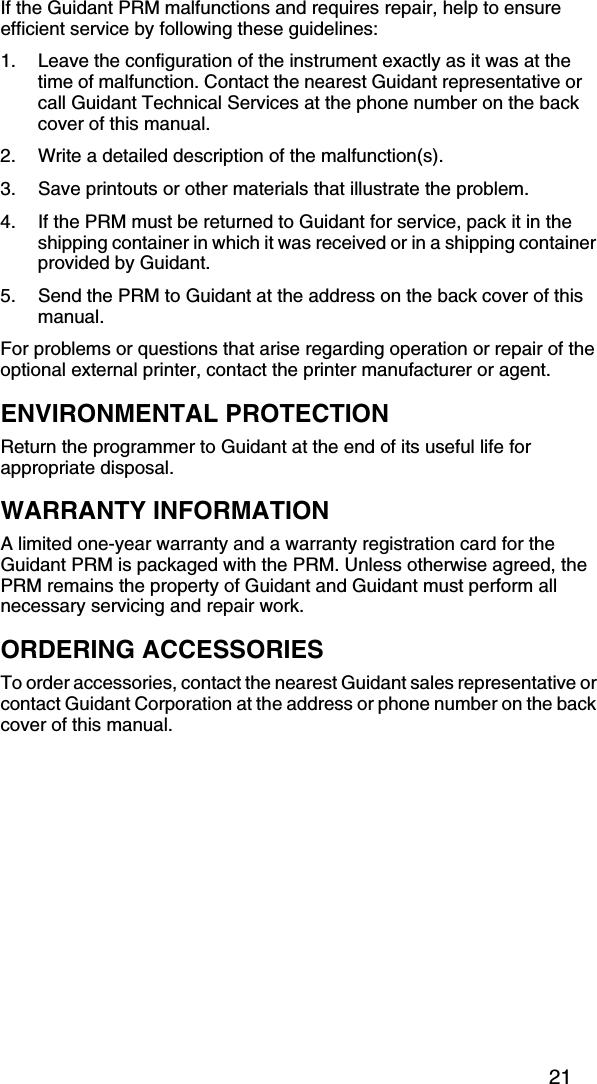
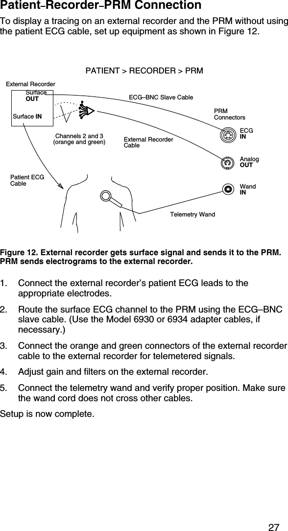
![4leakage requirements for medical products. Consequently, the external printer must be kept outside the patient environment (at least 4.9 feet [1.5 meters] away from the patient).Optional External MonitorThe use of an external monitor is optional. Contact your Guidant sales representative to determine which monitor(s) can be used.CAUTION: Although the external monitor meets leakage-current requirements for commercial products, it may not meet the reduced leakage requirements for medical products. Consequently, the external monitor must be kept outside the patient environment (at least 4.9 feet [1.5 meters] away from the patient).PREPARING THE PRM FOR USEPrepare the Telemetry Wand1. If the telemetry wand is to be used in a sterile field when using the PRM, it first must be sterilized with ethylene oxide or steam. To sterilize it, follow the instructions in the product literature for the wand. CAUTION: Remove the telemetry wand from all packaging material before sterilizing it.2. Plug the telemetry wand into the connector on the right side panel of the PRM (Figure 1).CAUTION: Avoid establishing telemetry communication between the PRM and the pulse generator when the PRM is in close proximity to monitors, high-frequency electrosurgical equipment, and strong magnetic fields, such as MRI devices. The telemetry link may be impaired and, in the case of MRI, may interfere with the PRM.Figure 1. Right side panel of the PRM.ECG ConnectorTelemetry Wand ConnectorAnalog Output ChannelStimulator Inputs Air IntakeAntenna for ZIP telemetry](https://usermanual.wiki/Boston-Scientific/CRM312005/User-Guide-550618-Page-10.png)
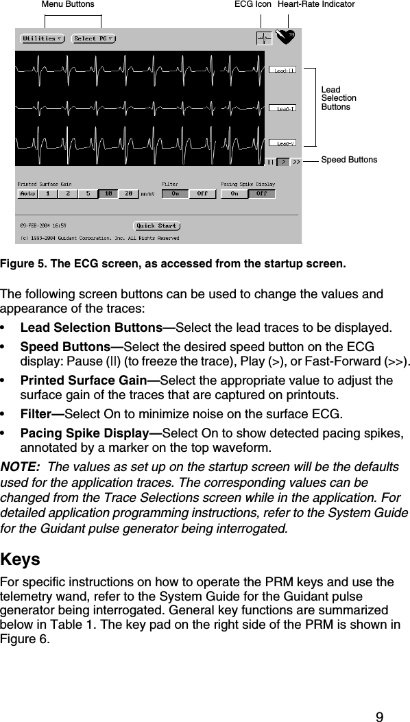
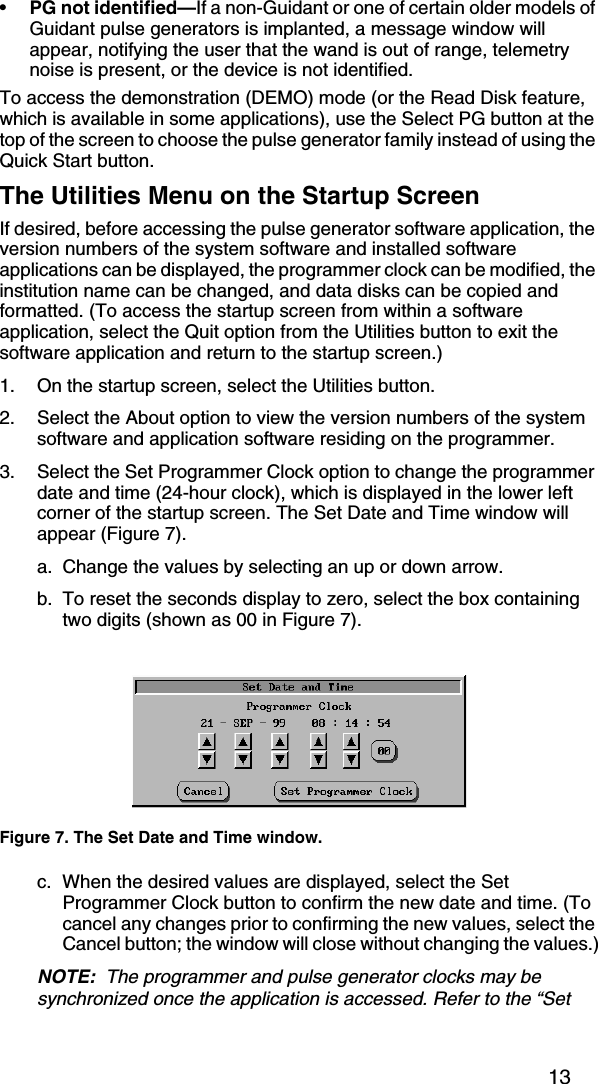
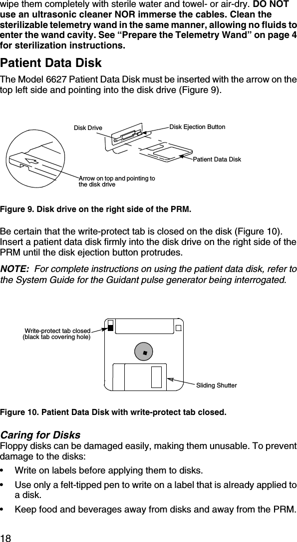
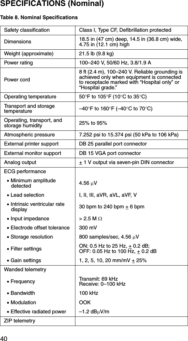
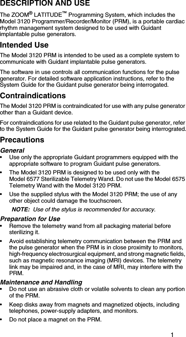
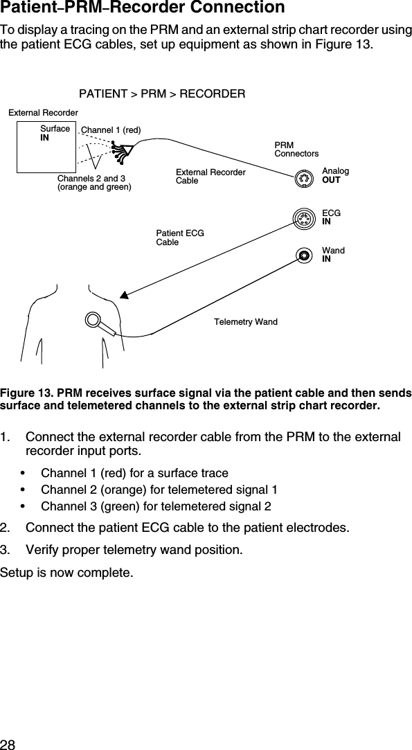
![19• Keep disks away from heat or direct sunlight. Disks should be stored at temperatures between 5°C and 60°C (41°F and 140°F).• Keep disks dry and stored in a dry area (with a relative humidity between 8 percent and 80 percent).• Do not bend disks.• Do not attach paper clips, staples, or rubber bands to disks.• Do not try to open the sliding shutter that covers the disks (Figure 10).• Never touch the exposed disk area beneath the sliding shutter.NOTE: The write-protect tab must be closed in order to record data to the disk and to print reports. If data cannot be recorded to the disk, check to see that the tab is positioned to cover the hole (Figure 10).CAUTION: Keep disks away from magnets and magnetized objects, including telephones, power supply adapters, and monitors.Operation and Storage ConditionsThe Model 3120 PRM requires careful handling. The hard-disk drive and the floppy-disk drive must be protected from abusive handling. To protect the PRM from damage:• Do not turn off the PRM while the drive is accessing data.• Do not subject the PRM to abusive shocks or vibrations.• When transporting the PRM from a cold environment to a warm environment, allow the PRM to warm to ambient temperature before use.• Do not place heavy objects on the PRM surface when closed or when in operation.• Do not place a magnet on the PRM.• Do not pour or splash liquid into or onto the PRM.• Do not strike, scratch, nick or otherwise abuse the touchscreen surface.• Do not disassemble the PRM.• Remove any disks from the drive prior to transporting the PRM.• Turn off the PRM, close all covers and doors and put down the antenna prior to transporting the PRM. • Unplug all external cables and cords prior to transporting the PRM.Operate the PRM within a temperature range of 50°F to 95°F(10°C to 35°C) and a humidity between 25 percent and 95 percent. Transport and store the PRM at temperatures between –40°F and 158°F (–40°C and 70°C), humidity of 25 percent to 95 percent, and pressure of 7.252 psi to 15.374 psi (50 kPa to 106 kPa). If the PRM has been stored in cold conditions (less than 50°F [10°C]), turn it on and let the fan run for at least one hour before use.](https://usermanual.wiki/Boston-Scientific/CRM312005/User-Guide-550618-Page-25.png)

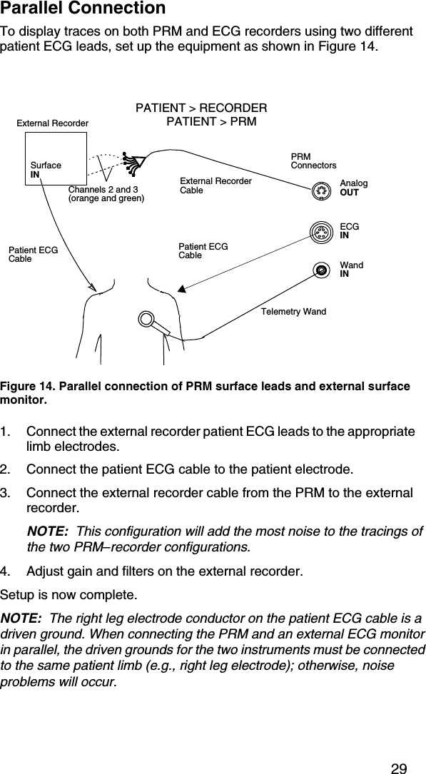
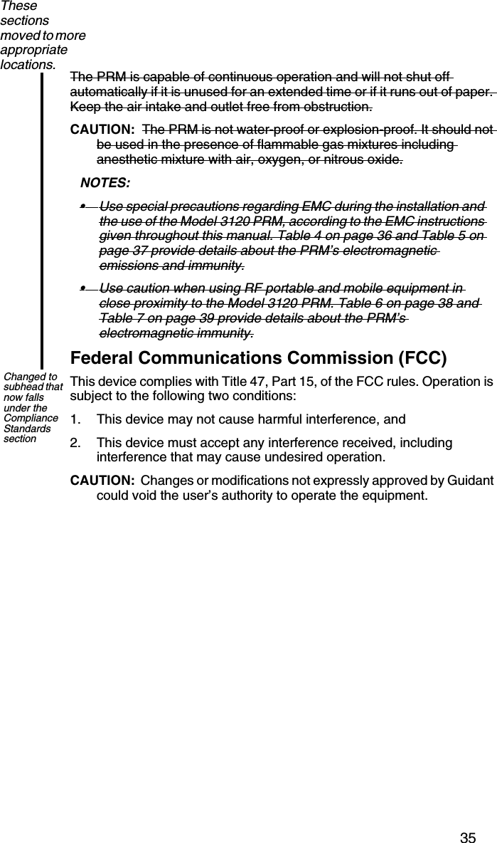
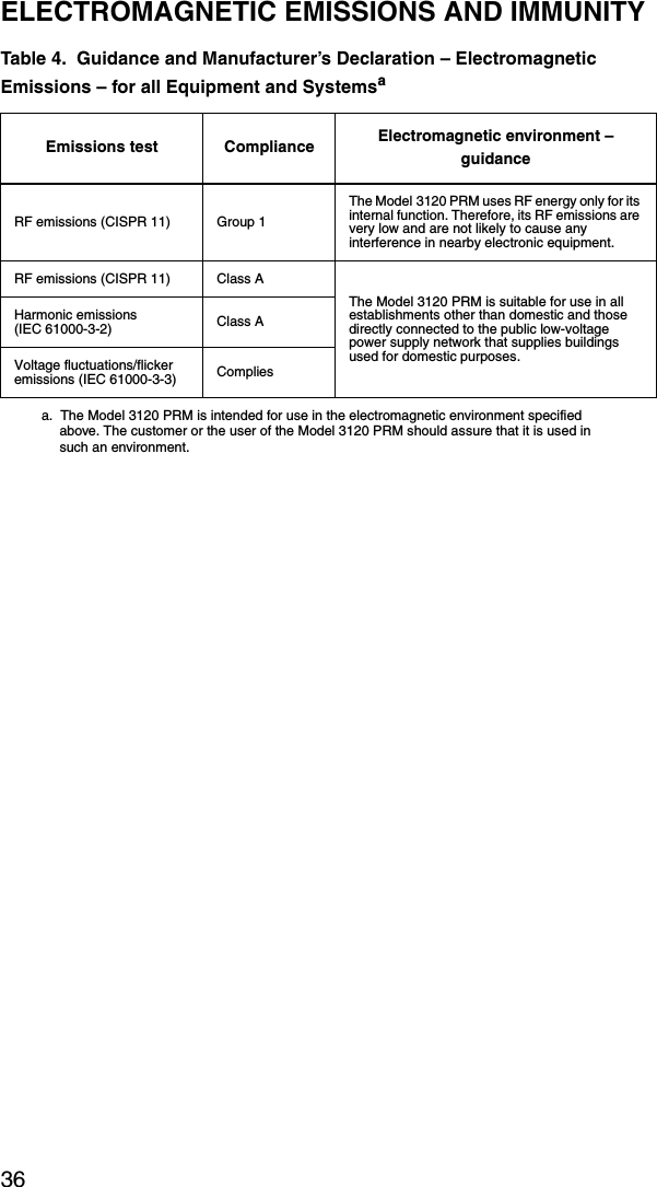
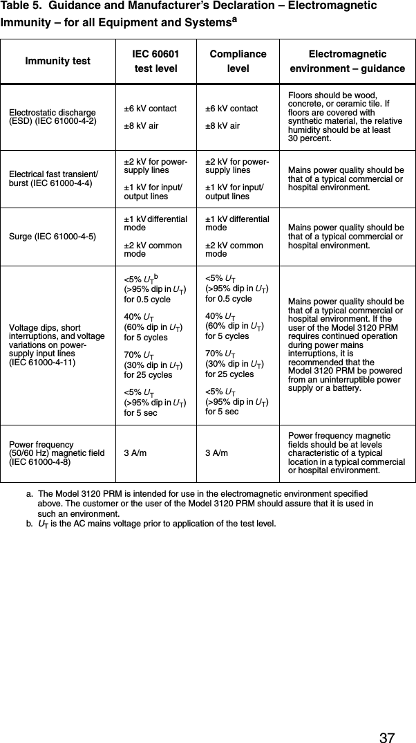
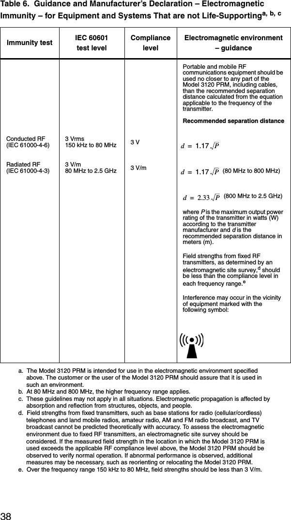
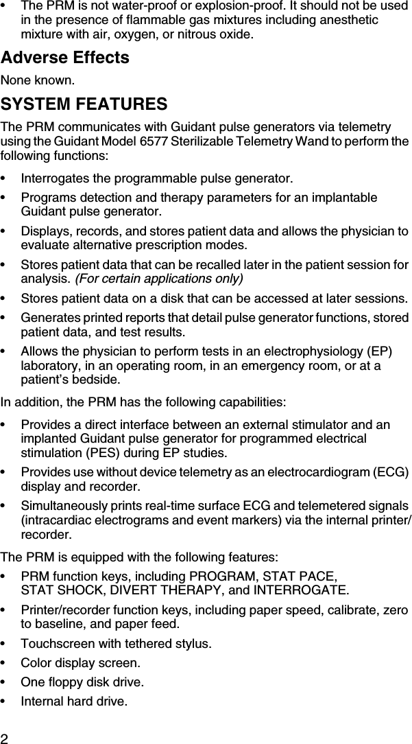
![34SAFETY AND ELECTROMAGNETIC COMPATIBILITY COMPLIANCE STANDARDSThis equipment complies with the safety, electromagnetic compatibility (EMC), and medical safety requirements.Safety StandardsThis equipment has been tested and found to comply with applicable safety portions of the following standards: • EN 60601-1:1990 + A1:1993 + A2:1995• UL 60601-1:2003• CAN/CSA-C22.2 No. 601.1-M90Electromagnetic Compability StandardsThis equipment has been tested and found to comply with the applicable portions of the electromagnetic compatibility (EMC) standards:• FCC Part 15.209:2004 + 15.207:2004 + 15.249:2004• EN 300 330-2 V1.1.1:2000• EN 300 220-1 V1.3.1:2000• EN 301 489-1 V1.4.1:2002NOTES: • Use special precautions regarding EMC during the installation and the use of the Model 3120 PRM, according to the EMC instructions given throughout this manual. Table 4 on page 36 and Table 5 on page 37 provide details about the PRM’s electromagnetic emissions and immunity.• Use caution when using RF portable and mobile equipment in close proximity to the Model 3120 PRM. Table 6 on page 38 and Table 7 on page 39 provide details about the PRM’s electromagnetic immunity.Medical Device DirectiveThis equipment has been tested and found to comply with the applicable limits for medical devices to IEC 60601-1-2:2001 [or EN 60601-1-2:2001 or Medical Device Directive 93/42/EEC]. This testing shows the device provides reasonable protection against harmful interference in a typical medical installation. However, there is no guarantee that interference will not occur in a particular installation. If this equipment does cause harmful interference to other devices or is negatively impacted by other devices, the user is encouraged to try to correct the interference by one or more of the following measures:• Reorient or relocate the devices.• Increase the separation between the devices.• Connect the equipment to an outlet on a different circuit.• Consult the manufacturer or field service technician for help.These notes belong with the EMC section, not the MDD section.](https://usermanual.wiki/Boston-Scientific/CRM312005/User-Guide-550618-Page-40.png)