Boston Scientific CRM312005 Model 3120 User Manual Draft Literature Labeling Review
Boston Scientific Corporation Model 3120 Draft Literature Labeling Review
Users Manual
Draft Literature/Labeling Review
002169 Rev C
You are being asked to review product literature/labeling because of your particular expertise. To minimize the number
of review cycles, please review the attached draft thoroughly and provide any comments, changes, or concerns at this
time.
• Please provide any comments on the attached draft by the due date indicated above.
• A non-response will be taken to mean that you accept the draft content "as is."
• Use the grid on the reverse side of this form to help focus your review efforts.
• Your signature is not required.
Note: After receiving comments and making any revisions that are required, Technical Communications will use
Windchill to route a final version of this literature/labeling to obtain required electronic signatures. Reviewers are
accountable for ensuring that they are trained on 028886, Cross-Functional Product Labeling Reviews, before
reviewing and approving labeling.
We appreciate your efforts and value your feedback. Thank you!
Reason for review / Writer’s comments:
Here is the updated ZOOM LATITUDE operator’s manual (US). The only changes since the last draft are as follows:
•Pages 20: Moved paragraph and caution back to here; should not have moved with standards (Tech Comm).
•Page 22: Added clarifying text to “printing stops” issue (Rick Stein, Engineering, and SCR 7048).
•Page 34–35: Made title more generic, deleted introductory sentence since it is repeated below but with qualifiers,
added subheads for each standard, moved notes up to the EMC section, deleted sections that belong elsewhere
(paragraph and caution on page 20 and notes in EMC section), and changed FCC to subhead so it now falls under
the Compliance Standards section (Tech Comm). Also, changed “applicable EMC standards” to “applicable por-
tions of the electromagnetic compatibility (EMC) standards” for clarity (Rick Stein, Engineering); had to write out
“EMC” because this is now first use of the acronym (Tech Comm).
Project
ZOOM LATITUDE operator’s manual (US) - 357043-001
(dual antenna)
Date sent: 2/28/05
Date due:
Tuesday, 3/01/05, 12:00 noon
Draft Review
Return to:
Kathleen Briggs
Mail Stop:
Department Mail
Stop
Reviewers For Tech Comm Use Only FYI Reviewers
(Return not necessary)
Mail
Stop
Rec’d OK Chgs Trans
Engineering Richard Stein
Engineering Holli Pheil
Engineering Yogendra Shah
Engineering Robert Bartlow
Marketing Amy Gaal
Regulatory Karen Alsop
Legal Susan Thompson

Instructions For Review
The table below was designed to help streamline the literature review process, to reduce the number of reviews per piece of literature, to reduce the amount of time you need
to spend reviewing each piece, and to help you focus your attention while reviewing literature.
Suggested Areas of Focus Legal Engineering Regulatory
Affairs Marketing Clinical
Programs
Technical
Services
Review cautions, warnings and notes. Are they appropriate, and are there any
that are missing? xx x x x
Review labeling for liability issues based on claims made in the labeling. x x x
Review warranty information. x x
Review labeling for any missing legal requirements. x
Review copyright and trademark notations. x x
Review product description, product handling (sterilization, shipping, storage,
biological testing). x
Review product specifications and units of measure (in tables and throughout
text). x
Review product features. Are the appropriate features highlighted and
described correctly? xx xx
Review illustrations. Are they appropriate to the corresponding text and
labeled correctly? xxx
Review tables and text relating to parameters, programmable values, nominal
settings, tolerances, and product functions. x
Review equipment hook-up procedures, lead-to-PG connections, etc. x x x x
Verify that all references to other Guidant products are still correct and
relevant. xx xx
Review labeling for missing information (features, specifications, government
requirements, legal requirements). xx x
Verify the list of items packaged with the product. x x
Compare the labeling to the system requirements specification, hazard
analysis, and any labeling-related SCRs or change issues. x
Verify the labeling against the clinical protocol and clinical study results. x x
Review labeling for references to other products that affect other submissions. x
Product naming and description x
Device longevity and warranty information x
Review that implant procedures are described correctly. xx
Verify that information provided in the labeling is consistent with other related
literature. x
Review the risk section. Are all applicable risks listed? x
Review labeling for clarity in device description and instructions for use. x
Review tables and text relating to parameters, programmable values, nominal
settings, tolerances, and product functions. x

Operator’s Manual
ZOOM® LATITUDE™
Programming System
MODEL 3120
RESTRICTED DEVICE: Federal law (USA) restricts
the sale, distribution, or use of this device to, by, or
on the lawful order of a physician.
Programmer/Recorder/Monitor (PRM)
CONTENTS
DESCRIPTION AND USE . . . . . . . . . . . . . . . . . . . . . . . . . . . . 1
Intended Use . . . . . . . . . . . . . . . . . . . . . . . . . . . . . . . . . . . 1
Contraindications . . . . . . . . . . . . . . . . . . . . . . . . . . . . . . . . 1
Precautions . . . . . . . . . . . . . . . . . . . . . . . . . . . . . . . . . . . . . 1
Adverse Effects . . . . . . . . . . . . . . . . . . . . . . . . . . . . . . . . . 2
SYSTEM FEATURES . . . . . . . . . . . . . . . . . . . . . . . . . . . . . . . . 2
System Accessories . . . . . . . . . . . . . . . . . . . . . . . . . . . . . . 3
Optional External Printer . . . . . . . . . . . . . . . . . . . . . . . . . . 3
Optional External Monitor . . . . . . . . . . . . . . . . . . . . . . . . . . 4
PREPARING THE PRM FOR USE . . . . . . . . . . . . . . . . . . . . . . 4
Prepare the Telemetry Wand . . . . . . . . . . . . . . . . . . . . . . . 4
Make External Cable Connections . . . . . . . . . . . . . . . . . . . 5
Start the PRM . . . . . . . . . . . . . . . . . . . . . . . . . . . . . . . . . . . 6
USING THE PRM . . . . . . . . . . . . . . . . . . . . . . . . . . . . . . . . . . . 7
Startup Screen . . . . . . . . . . . . . . . . . . . . . . . . . . . . . . . . . . 7
Touchscreen . . . . . . . . . . . . . . . . . . . . . . . . . . . . . . . . . . . . 7
Indicator Lights . . . . . . . . . . . . . . . . . . . . . . . . . . . . . . . . . . 8
ECG Display . . . . . . . . . . . . . . . . . . . . . . . . . . . . . . . . . . . . 8
Keys . . . . . . . . . . . . . . . . . . . . . . . . . . . . . . . . . . . . . . . . . . 9
Monitoring/Recording Functions . . . . . . . . . . . . . . . . . . . . 11
Using an External Recorder . . . . . . . . . . . . . . . . . . . . . . . 12
Using an External Printer . . . . . . . . . . . . . . . . . . . . . . . . . 12
Quick Start . . . . . . . . . . . . . . . . . . . . . . . . . . . . . . . . . . . . 12
The Utilities Menu on the Startup Screen . . . . . . . . . . . . . 13
The Select PG Option on the Startup Screen . . . . . . . . . . 14
Changing Parameter Values . . . . . . . . . . . . . . . . . . . . . . 15
MAINTENANCE AND HANDLING . . . . . . . . . . . . . . . . . . . . . 16
Loading the Paper . . . . . . . . . . . . . . . . . . . . . . . . . . . . . . 16
Thermal Paper Storage . . . . . . . . . . . . . . . . . . . . . . . . . . 17
Cleaning the PRM . . . . . . . . . . . . . . . . . . . . . . . . . . . . . . 17
Patient Data Disk . . . . . . . . . . . . . . . . . . . . . . . . . . . . . . . 18
Operation and Storage Conditions . . . . . . . . . . . . . . . . . . 19
PRM Storage . . . . . . . . . . . . . . . . . . . . . . . . . . . . . . . . . . 20
Preventive Maintenance . . . . . . . . . . . . . . . . . . . . . . . . . . 20

SERVICE . . . . . . . . . . . . . . . . . . . . . . . . . . . . . . . . . . . . . . . . 20
ENVIRONMENTAL PROTECTION . . . . . . . . . . . . . . . . . . . . . 21
WARRANTY INFORMATION . . . . . . . . . . . . . . . . . . . . . . . . . 21
ORDERING ACCESSORIES . . . . . . . . . . . . . . . . . . . . . . . . . 21
TROUBLESHOOTING . . . . . . . . . . . . . . . . . . . . . . . . . . . . . . 22
EXTERNAL CABLE CONNECTIONS . . . . . . . . . . . . . . . . . . . 25
Surface ECG Connections . . . . . . . . . . . . . . . . . . . . . . . . 26
Patient–Recorder–PRM Connection . . . . . . . . . . . . . . . . 27
Patient–PRM–Recorder Connection . . . . . . . . . . . . . . . . 28
Parallel Connection . . . . . . . . . . . . . . . . . . . . . . . . . . . . . 29
Suggested Electrode Locations . . . . . . . . . . . . . . . . . . . . 30
LABEL SYMBOLS . . . . . . . . . . . . . . . . . . . . . . . . . . . . . . . . . 31
SAFETY AND ELECTROMAGNETIC COMPATIBILITY
COMPLIANCE STANDARDS . . . . . . . . . . . . . . . . . . . . . . . . . 34
Safety Standards . . . . . . . . . . . . . . . . . . . . . . . . . . . . . . . 34
Electromagnetic Compability Standards . . . . . . . . . . . . . . 34
Medical Device Directive . . . . . . . . . . . . . . . . . . . . . . . . . 34
Federal Communications Commission (FCC) . . . . . . . . . 35
ELECTROMAGNETIC EMISSIONS AND IMMUNITY . . . . . . 36
SPECIFICATIONS (Nominal) . . . . . . . . . . . . . . . . . . . . . . . . . 40
1
DESCRIPTION AND USE
The ZOOM® LATITUDE™ Programming System, which includes the
Model 3120 Programmer/Recorder/Monitor (PRM), is a portable cardiac
rhythm management system designed to be used with Guidant
implantable pulse generators.
Intended Use
The Model 3120 PRM is intended to be used as a complete system to
communicate with Guidant implantable pulse generators.
The software in use controls all communication functions for the pulse
generator. For detailed software application instructions, refer to the
System Guide for the Guidant pulse generator being interrogated.
Contraindications
The Model 3120 PRM is contraindicated for use with any pulse generator
other than a Guidant device.
For contraindications for use related to the Guidant pulse generator, refer
to the System Guide for the Guidant pulse generator being interrograted.
Precautions
General
• Use only the appropriate Guidant programmers equipped with the
appropriate software to program Guidant pulse generators.
• The Model 3120 PRM is designed to be used only with the
Model 6577 Sterilizable Telemetry Wand. Do not use the Model 6575
Telemetry Wand with the Model 3120 PRM.
• Use the supplied stylus with the Model 3120 PRM; the use of any
other object could damage the touchscreen.
NOTE: Use of the stylus is recommended for accuracy.
Preparation for Use
• Remove the telemetry wand from all packaging material before
sterilizing it.
• Avoid establishing telemetry communication between the PRM and
the pulse generator when the PRM is in close proximity to monitors,
high-frequency electrosurgical equipment, and strong magnetic fields,
such as magnetic resonance imaging (MRI) devices. The telemetry
link may be impaired and, in the case of MRI, may interfere with the
PRM.
Maintenance and Handling
• Do not use an abrasive cloth or volatile solvents to clean any portion
of the PRM.
• Keep disks away from magnets and magnetized objects, including
telephones, power-supply adapters, and monitors.
• Do not place a magnet on the PRM.
2
• The PRM is not water-proof or explosion-proof. It should not be used
in the presence of flammable gas mixtures including anesthetic
mixture with air, oxygen, or nitrous oxide.
Adverse Effects
None known.
SYSTEM FEATURES
The PRM communicates with Guidant pulse generators via telemetry
using the Guidant Model 6577 Sterilizable Telemetry Wand to perform the
following functions:
• Interrogates the programmable pulse generator.
• Programs detection and therapy parameters for an implantable
Guidant pulse generator.
• Displays, records, and stores patient data and allows the physician to
evaluate alternative prescription modes.
• Stores patient data that can be recalled later in the patient session for
analysis. (For certain applications only)
• Stores patient data on a disk that can be accessed at later sessions.
• Generates printed reports that detail pulse generator functions, stored
patient data, and test results.
• Allows the physician to perform tests in an electrophysiology (EP)
laboratory, in an operating room, in an emergency room, or at a
patient’s bedside.
In addition, the PRM has the following capabilities:
• Provides a direct interface between an external stimulator and an
implanted Guidant pulse generator for programmed electrical
stimulation (PES) during EP studies.
• Provides use without device telemetry as an electrocardiogram (ECG)
display and recorder.
• Simultaneously prints real-time surface ECG and telemetered signals
(intracardiac electrograms and event markers) via the internal printer/
recorder.
The PRM is equipped with the following features:
• PRM function keys, including PROGRAM, STAT PACE,
STAT SHOCK, DIVERT THERAPY, and INTERROGATE.
• Printer/recorder function keys, including paper speed, calibrate, zero
to baseline, and paper feed.
• Touchscreen with tethered stylus.
• Color display screen.
• One floppy disk drive.
• Internal hard drive.
3
• High-speed four-inch (110 mm) thermal printer/recorder.
• Connections for slaved stimulation via an external signal source. (For
certain applications only)
• Connection for recording data on an external FM tape recorder or strip
chart recorder or both.
• Connection for an optional external printer.
• USB port for software installation by Guidant personnel.
•ZIP telemetry, which is a wandless, two-way radio frequency (RF)
communication option that allows the PRM system to communicate
with the pulse generator.
NOTE: This feature is not available for all pulse generators. For
more information, refer to the System Guide for the Guidant pulse
generator being interrogated.
System Accessories
The ZOOM LATITUDE Programming System consists of the Model 3120
PRM.
Other accessories for use with the PRM that can be ordered from Guidant
include the following:
• Model 3122 Antenna
• Model 3130 Accessory Kit
• Model 2902 AC Power Cord
• Model 6577 Sterilizable Telemetry Wand
• Model 6627 Patient Data Disks (10)
• Model 6750 Surface ECG Patient Cable
• Model 6979 Printer Paper (4)
• Model 6809 Accessory Kit
• Model 6892 Controller-Stimulator Cable
• Model 6924 External Recorder Cable
• Model 6629 ECG–BNC Slave Cable
• Model 6930 Stimulation Input Cable Adapters
• Model 6934 Phono-BNC Adapters
• Model 6977 VGA Extension Cable
WARNING: The use of any cables or accessories with the Model 3120
PRM other than those specified by Guidant in this manual may result
in increased emissions or decreased immunity of the Model 3120
PRM.
Optional External Printer
The use of an external printer is optional. Only compatible external
printers that have been tested and qualified for use should be used with
the Model 3120 PRM. Contact your Guidant sales representative to
determine which printer(s) can be used.
CAUTION: Although the external printer meets leakage-current
requirements for commercial products, it may not meet the reduced
4
leakage requirements for medical products. Consequently, the
external printer must be kept outside the patient environment (at
least 4.9 feet [1.5 meters] away from the patient).
Optional External Monitor
The use of an external monitor is optional. Contact your Guidant sales
representative to determine which monitor(s) can be used.
CAUTION: Although the external monitor meets leakage-current
requirements for commercial products, it may not meet the reduced
leakage requirements for medical products. Consequently, the
external monitor must be kept outside the patient environment (at
least 4.9 feet [1.5 meters] away from the patient).
PREPARING THE PRM FOR USE
Prepare the Telemetry Wand
1. If the telemetry wand is to be used in a sterile field when using the
PRM, it first must be sterilized with ethylene oxide or steam. To
sterilize it, follow the instructions in the product literature for the
wand.
CAUTION: Remove the telemetry wand from all packaging material
before sterilizing it.
2. Plug the telemetry wand into the connector on the right side panel of
the PRM (Figure 1).
CAUTION: Avoid establishing telemetry communication between the
PRM and the pulse generator when the PRM is in close proximity to
monitors, high-frequency electrosurgical equipment, and strong
magnetic fields, such as MRI devices. The telemetry link may be
impaired and, in the case of MRI, may interfere with the PRM.
Figure 1. Right side panel of the PRM.
ECG Connector
Telemetry Wand Connector
Analog Output Channel
Stimulator Inputs Air IntakeAntenna for ZIP telemetry
5
WARNING: The Model 3120 PRM may be interfered with by other
equipment, even if that other equipment complies with the
International Special Committee on Radio Interference (CISPR)
emission requirements.
Make External Cable Connections
1. Connect the Model 6750 Surface ECG Patient Cable to the ECG
connector on the right side of the PRM (Figure 1). This patient
connection is electrically isolated. Attach the surface electrodes to
the patient in a standard three-wire or five-wire configuration.
NOTE: The ECG subsystem may be sensitive to high-frequency
ambient noise when the ECG inputs are not terminated.
2. Connect the Model 6924 External Recorder Cable to the analog
output channel on the right side of the PRM (Figure 1). Connect the
other end to the multichannel recorder or external strip chart
recorder. The Model 3120 PRM has high-level analog outputs.
3. Connect the Model 6892 Controller-Stimulator Cable to the pacing
stimulation source connector marked “Stimulator Input” on the right
side of the PRM (Figure 1) and then into the corresponding terminal
on the electrical stimulation source.
4. (Optional) Connect the external printer to the PRM using the parallel
cable provided with the printer (Figure 2). The external printer must
be connected and activated to allow external reports to be printed.
5. (Optional) Connect the external monitor to the PRM using a standard
VGA cable (Figure 2). The Model 6977 VGA Extension Cable is
available from Guidant as an accessory.
NOTE: If the PRM is in close proximity to high-frequency electrosurgical
equipment, the surface ECG traces may exhibit noise interference. Refer
to “TROUBLESHOOTING” on page 22 for corrective action.
6
Start the PRM
Perform the following steps to start the PRM:
1. Connect the power cord into the alternating current (AC) connector
on the rear panel (Figure 3).
2. Plug the power cord into the appropriate AC outlet.
3. Raise the screen to a comfortable viewing angle.
4. Press the On/Off button (Figure 2).
5. Wait for the Guidant startup screen (Figure 4) to appear.
WARNING: The Model 3120 PRM should not be used adjacent to or
stacked with other equipment. If adjacent or stacked use is
necessary, the Model 3120 PRM should be checked for normal
operation in that configuration.
Figure 2. Left side panel of the PRM.
Figure 3. Rear panel of the PRM.
On/Off Button
External VGA Monitor Connector
External Printer Connector
USB Ports
Grounding Connector AC Connector
7
USING THE PRM
Startup Screen
The startup screen (Figure 4) displays the following information:
• The Utilities button allows access to programmer information and
setup functions prior to accessing the application software.
• The Select PG button allows the desired application to be chosen and
started.
• The ECG icon changes the screen display to an ECG display
available for patient diagnosis.
• The heart-rate indicator displays the intrinsic ventricular rate of the
patient.
•The Quick Start
® button is an automated method for starting the
appropriate application.
• The bottom left corner of the screen displays the date, time, and
programmer information.
Touchscreen
The Model 3120 PRM has a touchscreen. You can select a button or icon
on the touchscreen by touching the desired item with the stylus attached
to the PRM and lifting the stylus from the screen. Only one button or icon
may be selected at a time. Menu and parameter selection buttons will
activate when selected; the buttons in the parameter value palettes will
activate when the stylus is lifted from the screen.
CAUTION: Use the supplied stylus with the Model 3120 PRM; the use of
any other object could damage the touchscreen.
Figure 4. The startup screen is displayed when the programmer is powered
On.
Buttons
Heart-rate
Indicator
ECG Icon

8
NOTE: Use of the stylus is recommended for accuracy.
Indicator Lights
The Model 3120 PRM has three indicator lights on the upper left corner,
above the screen:
ECG Display
To display surface ECG signals on the PRM without device interrogation,
select the ECG icon on the startup screen (Figure 5). Connect the patient
leads; for instructions on proper patient cable connections, refer to
“EXTERNAL CABLE CONNECTIONS” on page 25. The PRM can display
three surface traces of up to six limb leads or one chest lead. The top
displayed lead will be annotated with the pacing spike marker if that
feature is selected. To display the pacing spike markers correctly, the
Lead II electrodes must be connected to the patient regardless of which
lead is displayed. The heart-rate indicator in the upper-right corner of the
startup screen will display the intrinsic ventricular rate as the trace runs.
WARNING: Operation of the Model 3120 PRM with physiological signals
that are lower than the minimum detectable amplitude may cause
inaccurate results. For details about the minimum amplitude, see
Table 8 on page 40.
Symbol Indicator Light Function
ZIP telemetry
Lit when ZIP telemetry has been
established and interrogation or
programming of ZIP-enabled PGs is
occurring.
Inductive telemetry
Lit when inductive, wanded telemetry has
been established and interrogation or
programming is occurring.
On Lit when the PRM is On.
9
The following screen buttons can be used to change the values and
appearance of the traces:
•Lead Selection Buttons—Select the lead traces to be displayed.
•Speed Buttons—Select the desired speed button on the ECG
display: Pause (||) (to freeze the trace), Play (>), or Fast-Forward (>>).
•Printed Surface Gain—Select the appropriate value to adjust the
surface gain of the traces that are captured on printouts.
•Filter—Select On to minimize noise on the surface ECG.
•Pacing Spike Display—Select On to show detected pacing spikes,
annotated by a marker on the top waveform.
NOTE: The values as set up on the startup screen will be the defaults
used for the application traces. The corresponding values can be
changed from the Trace Selections screen while in the application. For
detailed application programming instructions, refer to the System Guide
for the Guidant pulse generator being interrogated.
Keys
For specific instructions on how to operate the PRM keys and use the
telemetry wand, refer to the System Guide for the Guidant pulse
generator being interrogated. General key functions are summarized
below in Table 1. The key pad on the right side of the PRM is shown in
Figure 6.
Figure 5. The ECG screen, as accessed from the startup screen.
Speed Buttons
Lead
Selection
Buttons
Heart-Rate IndicatorMenu Buttons ECG Icon

10
Table 1. Key Functions
Left side of key pad:
0 (stop), 10, 25, 50,
and 100 mm/sec
(paper-speed keys)
Press the speed keys to specify the paper speed for
the internal printer/recorder. The printout will show
the date and time, lead(s) being printed, gain setting,
chart speed, and filter setting. To stop the printer/
recorder, press the speed key labeled “0” (zero).
Press the paper-feed key to scroll the printer paper
on the internal printer/recorder.
Press this key to cause the internal printer/recorder
to print a one-mV calibration pulse.
Press this key to force the trace back to the baseline
after a defibrillation shock.
Right side of key pad
Press STAT PACE when in telemetry communication
with the pulse generator to program predetermined
parameters for emergency bradycardia pacing.
Press DIVERT THERAPY when in telemetry
communication with the pulse generator to divert
tachycardia therapy delivery.
Press STAT SHOCK when in telemetry
communication with the pulse generator to program
predetermined high-energy parameters for
emergency shock delivery.
STAT PACE
DIVERT THERAPY
STAT SHOCK
11
Monitoring/Recording Functions
Surface ECG
Pressing any speed key will run a surface ECG if the surface ECG patient
cable is connected to the PRM and electrodes are attached to the patient
(unless a report is being printed). For detailed instructions, refer to “ECG
Display” on page 8.
Intracardiac Electrogram
Intracardiac electrograms may be printed or displayed and event markers
may be printed by the PRM. For detailed instructions, refer to the System
Guide for the Guidant pulse generator being interrogated.
Press PROGRAM when in telemetry communication
with the pulse generator to transmit new parameter
values to the pulse generator.
Press INTERROGATE when in telemetry
communication with the pulse generator to obtain
information stored in the pulse generator’s memory.
Figure 6. Model 3120 PRM right-side keypad.
Table 1. Key Functions
PROGRAM
INTERROGATE
STAT PACE STAT SHOCK
DIVERT THERAPY
PROGRAM INTERROGATE
12
Using an External Recorder
To view the surface ECG traces on an external recorder, press the
desired speed key on the external printer/recorder while the traces are
displayed on the PRM screen. See “EXTERNAL CABLE
CONNECTIONS” on page 25 for instructions on connecting the PRM to
the external recorder. Refer to the external recorder manual for
instructions specific to its operation.
Using an External Printer
If supported by the software application currently running, an optional
external printer can be used. To print reports to an external printer, first
connect the printer to the Model 3120 PRM using the parallel cable. The
cable connects the external printer to the PRM via the external printer
connector (Figure 2). The external printer must be connected and
activated to allow external reports to be printed. For more information, see
“Optional External Printer” on page 3.
NOTE: Equipment connected to the serial port and other external
connections must comply with the respective IEC standards (e.g. IEC 950
for data processing equipment and IEC 601-1 for medical equipment).
Furthermore all configurations shall comply with the system standard IEC
601-1-1. Everybody who connects additional equipment to the signal
input part or signal output part configures a medical system, and is
therefore responsible that the system complies with the requirements of
the system standard IEC 601-1-1. If in doubt, consult Guidant Technical
Services or your local Guidant sales representative.
Quick Start
The Quick Start button is used to automatically identify and interrogate the
implanted pulse generator. Place the telemetry wand over the pulse
generator, and select the Quick Start button. A message window will
appear, indicating one of the following conditions, based on the implanted
device:
•Application Startup in Progress—If the software for the implanted
device is installed on the PRM, the PRM will identify the device, open
the correct application, and automatically interrogate the pulse
generator.
•Software not installed—If the software application for the implanted
device is available for the PRM but not installed on it, a message
window will appear, identifying the device and stating that the software
is not installed on the PRM.
•Software not available on PRM—If an older model of Guidant device
is identified, a message window will appear, informing the user that he
or she must use a Model 2035 or 2901 programmer to interrogate and/
or program the device. The model number of the software module or
application will also be identified.
13
•PG not identified—If a non-Guidant or one of certain older models of
Guidant pulse generators is implanted, a message window will
appear, notifying the user that the wand is out of range, telemetry
noise is present, or the device is not identified.
To access the demonstration (DEMO) mode (or the Read Disk feature,
which is available in some applications), use the Select PG button at the
top of the screen to choose the pulse generator family instead of using the
Quick Start button.
The Utilities Menu on the Startup Screen
If desired, before accessing the pulse generator software application, the
version numbers of the system software and installed software
applications can be displayed, the programmer clock can be modified, the
institution name can be changed, and data disks can be copied and
formatted. (To access the startup screen from within a software
application, select the Quit option from the Utilities button to exit the
software application and return to the startup screen.)
1. On the startup screen, select the Utilities button.
2. Select the About option to view the version numbers of the system
software and application software residing on the programmer.
3. Select the Set Programmer Clock option to change the programmer
date and time (24-hour clock), which is displayed in the lower left
corner of the startup screen. The Set Date and Time window will
appear (Figure 7).
a. Change the values by selecting an up or down arrow.
b. To reset the seconds display to zero, select the box containing
two digits (shown as 00 in Figure 7).
c. When the desired values are displayed, select the Set
Programmer Clock button to confirm the new date and time. (To
cancel any changes prior to confirming the new values, select the
Cancel button; the window will close without changing the values.)
NOTE: The programmer and pulse generator clocks may be
synchronized once the application is accessed. Refer to the “Set
Figure 7. The Set Date and Time window.
14
Clock” section in the System Guide for the Guidant pulse generator
being interrograted.
4. Select the About option to update the institution name. If the
programmer has been moved to a different institution, the name of
the institution as it appears on the startup screen can be changed.
For instructions on entering new data, refer to “Changing Parameter
Values” on page 15.
NOTE: The institution name also is displayed in the heading of
printed reports.
5. Select the Format Disk option to erase all data from a Model 6627
Patient Data Disk and reformat it so new data can be saved on the
disk. Follow the directions displayed in the message windows.
6. Select the Copy Disk option to copy patient data from one disk (the
source disk) to another (the destination disk). Do not use a
destination disk that contains patient data, because the existing data
will be lost. Follow the directions displayed in the message windows.
(This function performs in the same manner as the Copy Disk
function of the software application; refer to the System Guide for the
Guidant pulse generator being interrogated.)
The Select PG Option on the Startup Screen
This option allows the software application to be selected manually. Use
this option to access the DEMO mode (or the Read Disk feature, which is
available in some applications). (You can also use this option to
interrogate a pulse generator, but you may find it more convenient to use
the Quick Start feature described earlier in this manual.)
1. To access the desired software application without using the Quick
Start feature, select the Select PG button.
2. The names of the available software applications will appear. Select
the applicable software application. Each application communicates
with its pulse-generator family.
3. A screen will appear with options to interrogate the pulse generator
or use the DEMO mode. (Some applications will also display the
option to read a patient data disk.)
4. To become familiar with the software without interrogating a pulse
generator, select the DEMO button; the main application screen will
be displayed and the DEMO logo will appear at the top of the screen.
The screens displayed during the DEMO mode reflect the software
application family’s device features and programmable values.
NOTE: STAT PACE, STAT SHOCK, and DIVERT THERAPY
commands are functional in DEMO mode only if the telemetry wand
is positioned over the pulse generator.
5. To exit the DEMO mode, depending on which application you are
using, select the New Patient or Quit options from either the Utilities
15
button or the Exit button. For more information about these options,
refer to the System Guide for the Guidant pulse generator being
interrogated.
6. To proceed with an interrogation session or read data from a patient
data disk (which is a feature that is available in some applications),
refer to the System Guide for the Guidant pulse generator being
interrogated.
Changing Parameter Values
The screens for many of the features contain parameter information,
including parameter names, values for the present parameter settings,
value boxes to accommodate value changes, and buttons to cancel
changes. Many screens display two columns next to the parameter
names: the Present column and the Change column. The Present column
displays the currently programmed value for each parameter, and the
Change column displays value boxes that allow the clinician to make
changes to the parameters. If a particular parameter is not applicable in
the current mode, dashes will be displayed in the Present column. If a
particular parameter is not applicable to the mode in the Change column,
that parameter’s value box is not displayed.
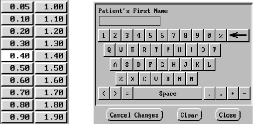
Palette Window: To change the parameter values, first select the
appropriate parameter’s value box in the Change column. A palette
window will appear (as shown in Figure 8). Select a value from the palette
window (by touching the desired value and lifting the stylus from the
screen). Touching the screen outside a window will close it without
making a selection. When changes have been made to parameter values,
the data appear in the Change box until programmed into the pulse
generator.
In some screens (e.g., Patient Data screens), data are not displayed in
Present and Change columns. These screens display value boxes that
Figure 8. Types of windows enabling value changes.
Palette Window Keyboard Window
16
require unique data to be entered. Typically, the data are entered from a
keyboard window (as shown in Figure 8). The values entered will remain
in the value boxes when programmed; they will not move from a Change
column to a Present column.
Keyboard Window: Touch the first character of the new value; it will
appear in the data-entry box in the graphic keyboard. Continue until the
entire new entry appears in the box. To delete one character at a time,
starting with the last character, select the left arrow key on the graphic
keyboard. Each time the left arrow key is selected, a character will be
deleted in the box. To cancel any deletions or additions just made, select
the Cancel Changes button. When all the appropriate characters have
been selected, select the Close button on the graphic keyboard.
NOTE: If, when the graphic keyboard initially appears, it contains data in
the value box, select the Clear button to delete all the characters in the
value box.
Copy button: On screens that contain a Copy button, you can simply
copy parameter values from one screen to another. Select the Copy
button. A window will appear with a Copy From column and a Copy To
column, with buttons below the columns. Select the desired buttons in
both columns, and then select the Copy button.
To program the device, follow the instructions in the System Guide for the
Guidant pulse generator being interrogated.
NOTE: If additional parameters require reprogramming, repeat these
steps. Multiple parameter changes can be programmed at one time
(batch programming).
MAINTENANCE AND HANDLING
Loading the Paper
The internal printer/recorder uses four-inch wide (110 mm)
thermosensitive printing paper. Model 6979 Printer Paper refills can be
ordered from Guidant.
Use the following procedure to load paper into the internal printer/
recorder:
1. Open the printer door.
2. If any sheets from the previous pack remain but did not feed, remove
them and rotate the roller with clean fingertips to remove any small
pieces of paper still under the printhead.
3. If the paper is still enclosed in its original plastic packaging, remove
this covering from the pack.
4. Orient the pack such that the pagination mark (which is the small
black box that is visible inside the pack if you lift up the top sheet of
paper) is located nearest to the front of the programmer. (For a visual
17
of how to orient the paper, refer to the paper liner inside the PRM.)
Insert the pack into the printer/recorder.
NOTE: You must use paper with pagination markings. Paper will not
paginate properly if paper does not have markings.
5. Unfold one sheet of paper, and allow the unfolded sheet to lie flat
across the well of the stylus.
6. Close the printer door completely. The printer/recorder will
automatically begin the paper-loading sequence and will stop at the
first pagination mark after paper is detected. If the paper’s edges are
wrinkled, wait for four or five pages to feed through the printer. The
printer will self-align the paper to its proper position.
The printer/recorder is now ready to resume printing.
For information regarding loading paper into the optional external printer,
refer to the user manual for the printer.
Thermal Paper Storage
Store the heat-sensitive paper for the internal printer/recorder in a cool,
dark environment. Do not attempt to erase the printer/recorder paper.
Printed paper will last approximately 30 days under direct fluorescent
light. To ensure the permanence of a patient’s record, store the printed
paper away from direct sunlight, heat, or fumes from organic
compounds. Storage temperatures above 149°F (65°C), sustained
exposure to direct sunlight, or exposure to high humidity, acetone,
ammonia, alcohols, or other organic compounds may cause the paper to
discolor.
NOTES:
• If printed reports are to be kept for prolonged periods, you must
make a photocopy of the thermosensitive paper as this paper is not
intended for long-term retention and will lose legibility over time.
• Some brands of adhesive tape applied to a printed report will fade
the printing after 30 days.
Cleaning the PRM
Clean the housing and touchscreen of the PRM with a soft cloth lightly
dampened with water.
Clean the printer/recorder with a dry, soft brush to eliminate dust and
particles that may accumulate during printing and storage.
CAUTION: Do not use an abrasive cloth or volatile solvents to clean any
portion of the PRM.
The cables used with the PRM are not sterile when packaged. When
necessary, clean the cables with a soft cloth dampened with a mild
cleaning solution (e.g., Liqui-nox for the sterilizable telemetry wand;
Borax or a 1:10 bleach solution for other cables). Using the same method,
18
wipe them completely with sterile water and towel- or air-dry. DO NOT
use an ultrasonic cleaner NOR immerse the cables. Clean the
sterilizable telemetry wand in the same manner, allowing no fluids to
enter the wand cavity. See “Prepare the Telemetry Wand” on page 4
for sterilization instructions.
Patient Data Disk
The Model 6627 Patient Data Disk must be inserted with the arrow on the
top left side and pointing into the disk drive (Figure 9).
Be certain that the write-protect tab is closed on the disk (Figure 10).
Insert a patient data disk firmly into the disk drive on the right side of the
PRM until the disk ejection button protrudes.
NOTE: For complete instructions on using the patient data disk, refer to
the System Guide for the Guidant pulse generator being interrogated.
Caring for Disks
Floppy disks can be damaged easily, making them unusable. To prevent
damage to the disks:
• Write on labels before applying them to disks.
• Use only a felt-tipped pen to write on a label that is already applied to
a disk.
• Keep food and beverages away from disks and away from the PRM.
Figure 9. Disk drive on the right side of the PRM.
Figure 10. Patient Data Disk with write-protect tab closed.
Arrow on top and pointing to
the disk drive
Disk Drive Disk Ejection Button
Patient Data Disk
Write-protect tab closed
(black tab covering hole)
Sliding Shutter
19
• Keep disks away from heat or direct sunlight. Disks should be stored
at temperatures between 5°C and 60°C (41°F and 140°F).
• Keep disks dry and stored in a dry area (with a relative humidity
between 8 percent and 80 percent).
• Do not bend disks.
• Do not attach paper clips, staples, or rubber bands to disks.
• Do not try to open the sliding shutter that covers the disks (Figure 10).
• Never touch the exposed disk area beneath the sliding shutter.
NOTE: The write-protect tab must be closed in order to record data to the
disk and to print reports. If data cannot be recorded to the disk, check to
see that the tab is positioned to cover the hole (Figure 10).
CAUTION: Keep disks away from magnets and magnetized objects,
including telephones, power supply adapters, and monitors.
Operation and Storage Conditions
The Model 3120 PRM requires careful handling. The hard-disk drive and
the floppy-disk drive must be protected from abusive handling. To protect
the PRM from damage:
• Do not turn off the PRM while the drive is accessing data.
• Do not subject the PRM to abusive shocks or vibrations.
• When transporting the PRM from a cold environment to a warm
environment, allow the PRM to warm to ambient temperature before
use.
• Do not place heavy objects on the PRM surface when closed or when
in operation.
• Do not place a magnet on the PRM.
• Do not pour or splash liquid into or onto the PRM.
• Do not strike, scratch, nick or otherwise abuse the touchscreen
surface.
• Do not disassemble the PRM.
• Remove any disks from the drive prior to transporting the PRM.
• Turn off the PRM, close all covers and doors and put down the
antenna prior to transporting the PRM.
• Unplug all external cables and cords prior to transporting the PRM.
Operate the PRM within a temperature range of 50°F to 95°F(10°C to
35°C) and a humidity between 25 percent and 95 percent. Transport and
store the PRM at temperatures between –40°F and 158°F (–40°C and
70°C), humidity of 25 percent to 95 percent, and pressure of 7.252 psi to
15.374 psi (50 kPa to 106 kPa). If the PRM has been stored in cold
conditions (less than 50°F [10°C]), turn it on and let the fan run for at least
one hour before use.

20
The PRM is capable of continuous operation and will not shut off
automatically if it is unused for an extended time or if it runs out of paper.
Keep the air intake and outlet free from obstruction.
CAUTION: The PRM is not water-proof or explosion-proof. It should not
be used in the presence of flammable gas mixtures including
anesthetic mixture with air, oxygen, or nitrous oxide.
PRM Storage
1. If using a patient data disk, remove disk from the disk drive by
pressing the disk ejection button (Figure 9), and store the disk in a
safe place.
2. Exit the current software application.
3. Press the On/Off button to turn off the power (Figure 2).
NOTE: Before unplugging the power cord to move the PRM, always
exit the software application and press the On/Off button to turn off
the PRM.
4. Unplug the power cord from the wall.
5. Unplug the cables from the back and side panels and other
equipment.
6. Lower the screen until the front latch locks in place.
NOTE: The programmer is not intended to be rested or stored in an
upright position (resting on rear panel with handle on top).
Preventive Maintenance
The user should inspect and/or test the following at regular intervals:
• Mechanical and functional integrity of cables and accessories.
• Mechanical and functional integrity of the PRM.
• Legibility and adherence of the PRM’s labels.
• Earth resistance to 0.1 ohms.
• Earth leakage current to 500 microamperes, NC; 1,000
microamperes, SFC.
• Patient leakage current to 10 microamperes, NC; 50 microamperes,
SFC (per EN 60601-1 as referenced earlier in this manual).
• Startup screen appears a few seconds after the user turns on the
PRM.
The PRM contains no user-accessible fuses or batteries.
SERVICE
For questions regarding operation or repair of the PRM, call the nearest
Guidant representative or call Guidant Technical Services at the phone
number on the back cover of this manual. The PRM must be serviced by
Guidant personnel only.
This section
should not have
moved with the
standards.
21
If the Guidant PRM malfunctions and requires repair, help to ensure
efficient service by following these guidelines:
1. Leave the configuration of the instrument exactly as it was at the
time of malfunction. Contact the nearest Guidant representative or
call Guidant Technical Services at the phone number on the back
cover of this manual.
2. Write a detailed description of the malfunction(s).
3. Save printouts or other materials that illustrate the problem.
4. If the PRM must be returned to Guidant for service, pack it in the
shipping container in which it was received or in a shipping container
provided by Guidant.
5. Send the PRM to Guidant at the address on the back cover of this
manual.
For problems or questions that arise regarding operation or repair of the
optional external printer, contact the printer manufacturer or agent.
ENVIRONMENTAL PROTECTION
Return the programmer to Guidant at the end of its useful life for
appropriate disposal.
WARRANTY INFORMATION
A limited one-year warranty and a warranty registration card for the
Guidant PRM is packaged with the PRM. Unless otherwise agreed, the
PRM remains the property of Guidant and Guidant must perform all
necessary servicing and repair work.
ORDERING ACCESSORIES
To order accessories, contact the nearest Guidant sales representative or
contact Guidant Corporation at the address or phone number on the back
cover of this manual.

22
TROUBLESHOOTING
If the PRM does not operate properly, check that electrical cords and
cables are securely connected and that cords and cables are in good
working order (i.e., free of visible defects). Table 2 indicates possible
causes and corrective actions for PRM problems. For external printer
problems, refer to the manual for the external printer.
Table 2. Possible Causes and Corrective Actions for PRM Problems
Symptom Possible Cause Corrective Action
Internal printer/
recorder does
not function
No AC line voltage
Check that power cord is
plugged securely into the rear
panel of the PRM.
Change to a different electrical
outlet.
Paper jam Clear paper path of any
obstruction.
No paper Add paper.
Internal printer/
recorder: paper-
feed problems
Paper
misaligned Reload paper.
Paper-feed
obstruction
Clear obstruction from around
the paper supply.
Internal printer/
recorder: no
print visible
Paper loaded upside
down
Reload paper. (See “Loading
the Paper” on page 16.)
Internal printer/
recorder:
printing stops
Application did not
handle print request
If the touchscreen is
responsive, select the Utilities
button. From the Utilities menu,
select Quit. In the window that
appears, select Cancel Printing
and then select Close. Turn on
the programmer and try
printing any incomplete items
again.
If the touchscreen is not
responsive, turn off the
programmer. Turn on the
programmer and try printing
any incomplete items again.
External printer
does not
function
No paper, paper jam,
printer door open, toner
cartridge not installed
properly, printer power
not On, printer not
connected
Consult the manual for the
external printer to determine
the issue.

23
No analog
output
Using incorrect output
port and/or
connections
Recheck connection of the
Model 6924 External Recorder
Cable.
Patient data disk
error
Using disk created for a
previous model of PRM
or unformatted floppy
disk
Use only Guidant Model 6627
Patient Data Disks.
Write-protect tab open Close write-protect tab.
Noise problems:
ECG
Improper patient
connections
Recheck patient leads for
adequate skin contact and
correct limb lead placement.
Excessive radio
emissions from
equipment
Check surrounding area for
electrical equipment that is
powered on and not needed.
Move unneeded equipment
away from patient and/or PRM,
or turn off unneeded
equipment. Consult ECG
textbooks for additonal ECG
techniques.
Telemetry: no
communication
Incorrect application
software or incorrect
PRM for pulse
generator
Install proper application
software for pulse generator in
use.
Incomplete telemetry
communication
Reposition wand over the
device; repeat interrogation.
Te l em e tr y:
intermittent
communication
Incorrect telemetry
wand
Use only the Guidant
Model 6577 Sterilizable
Telemetry Wand.
Excessive radio
emissions from
equipment
Check surrounding area for
electrical equipment that is
powered on and not needed.
Move unneeded equipment
away from patient and/or PRM,
or turn off unneeded
equipment.
Incomplete telemetry
communication
Reposition wand over the
device; repeat interrogation.
Displayed clock
does not
consistently
keep time after
setting
Low battery Return to Guidant for
replacement of clock battery.
Table 2. Possible Causes and Corrective Actions for PRM Problems
Symptom Possible Cause Corrective Action

24
Programmer not
responding
Programmer not
functioning
Turn off programmer, and then
turn on programmer. If this
does not correct the issue,
contact Guidant Technical
Services at the phone number
on the back cover of this
manual.
Table 2. Possible Causes and Corrective Actions for PRM Problems
Symptom Possible Cause Corrective Action
25
EXTERNAL CABLE CONNECTIONS
The following cables are required for use with the Model 3120
Programmer/ Recorder/Monitor when using the configurations described
in this section.
• Model 6924 External Recorder Cable: a six-channel DIN – six BNC
cables (color-coded and numbered) for connection of the PRM analog
output signals to another strip chart recorder or monitor.
• Model 6750 Surface ECG Patient Cable: a six-pin amphenol ECG
cable for connecting the patient directly to the PRM.
• Model 6629 ECG–BNC Slave Cable: used for input of patient ECG
signals to the PRM from an external monitor or recorder.
• Model 6577 Sterilizable Telemetry Wand.
The PRM also has two adapter kits that adapt cables with BNC
connectors to fit other sockets:
• Model 6930: BNC–dual banana plug
BNC–pin tip
BNC–alligator clip adapters
• Model 6934: BNC–phono adapter
Refer to Figure 11 for cable connections.
Figure 11. Cable connections for the Model 3120 PRM (right side panel).
123456
External Recorder Cable:
Channel 1 (red) - surface ECG
Channel 2 (orange) - telemetered signal 1
Channel 3 (green) - telemetered signal 2
Channels 4, 5, 6 - not active
Telemetry Wand Connector
Patient ECG Cable or
ECG–BNC Slave Cable
Telemetry Wand
Analog Output Channel ECG Connector
26
Surface ECG Connections
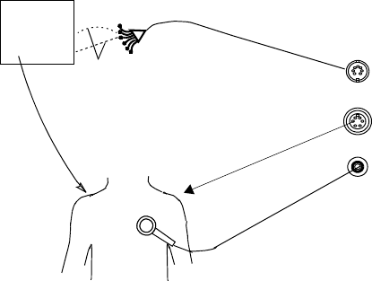
Three cable–electrode configurations frequently used to generate surface
ECGs include the following:
• Patient to external recorder to PRM (Figure 12)
• Patient to PRM to external recorder (Figure 13)
• Simultaneous connections from patient to PRM and patient to external
recorder (Figure 14)
NOTE: Annotated event markers cannot be sent to an external recorder.
Also, suggested electrode locations on a patient are shown (Figure 15).
27
Patient–Recorder–PRM Connection
To display a tracing on an external recorder and the PRM without using
the patient ECG cable, set up equipment as shown in Figure 12.
1. Connect the external recorder’s patient ECG leads to the
appropriate electrodes.
2. Route the surface ECG channel to the PRM using the ECG–BNC
slave cable. (Use the Model 6930 or 6934 adapter cables, if
necessary.)
3. Connect the orange and green connectors of the external recorder
cable to the external recorder for telemetered signals.
4. Adjust gain and filters on the external recorder.
5. Connect the telemetry wand and verify proper position. Make sure
the wand cord does not cross other cables.
Setup is now complete.
Figure 12. External recorder gets surface signal and sends it to the PRM.
PRM sends electrograms to the external recorder.
PATIENT > RECORDER > PRM
Telemetry Wand
Patient ECG
Cable
External Recorder
ECG–BNC Slave Cable
External Recorder
Cable
PRM
Connectors
ECG
IN
Wand
IN
Analog
OUT
Surface IN
Surface
OUT
Channels 2 and 3
(orange and green)
28
Patient–PRM–Recorder Connection
To display a tracing on the PRM and an external strip chart recorder using
the patient ECG cables, set up equipment as shown in Figure 13.
1. Connect the external recorder cable from the PRM to the external
recorder input ports.
• Channel 1 (red) for a surface trace
• Channel 2 (orange) for telemetered signal 1
• Channel 3 (green) for telemetered signal 2
2. Connect the patient ECG cable to the patient electrodes.
3. Verify proper telemetry wand position.
Setup is now complete.
Figure 13. PRM receives surface signal via the patient cable and then sends
surface and telemetered channels to the external strip chart recorder.
Telemetry Wand
Patient ECG
Cable
External Recorder
External Recorder
Cable
PATIENT > PRM > RECORDER
Channel 1 (red)
PRM
Connectors
ECG
IN
Wand
IN
Analog
OUT
Surface
IN
Channels 2 and 3
(orange and green)
29
Parallel Connection
To display traces on both PRM and ECG recorders using two different
patient ECG leads, set up the equipment as shown in Figure 14.
1. Connect the external recorder patient ECG leads to the appropriate
limb electrodes.
2. Connect the patient ECG cable to the patient electrode.
3. Connect the external recorder cable from the PRM to the external
recorder.
NOTE: This configuration will add the most noise to the tracings of
the two PRM–recorder configurations.
4. Adjust gain and filters on the external recorder.
Setup is now complete.
NOTE: The right leg electrode conductor on the patient ECG cable is a
driven ground. When connecting the PRM and an external ECG monitor
in parallel, the driven grounds for the two instruments must be connected
to the same patient limb (e.g., right leg electrode); otherwise, noise
problems will occur.
Figure 14. Parallel connection of PRM surface leads and external surface
monitor.
Telemetry Wand
Patient ECG
Cable
External Recorder
External Recorder
Cable
PRM
Connectors
ECG
IN
Wand
IN
Analog
OUT
Surface
IN
Patient ECG
Cable
PATIENT > RECORDER
PATIENT > PRM
Channels 2 and 3
(orange and green)
30
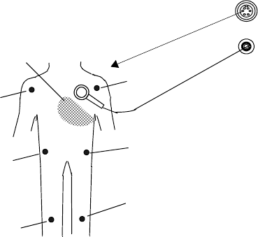
Suggested Electrode Locations
Figure 15 describes suggested locations for electrodes.
Figure 15. Suggested electrode locations.
Patient ECG Cable
PATIENT > ECG CABLE > PRM
Approx.
area for C,
V1–V6
(Brown)
Telemetry Wand
ECG
IN
Wand
IN
Primary LL (Red)
Alternate LL
(Red)
Primary RL
(Green)
Alternate RL
(Green)
RA (White)
LA (Black)
Key
RA (Right Arm)
LA (Left Arm)
RL (Right Leg)
LL (Left Leg)
C (Chest)
31
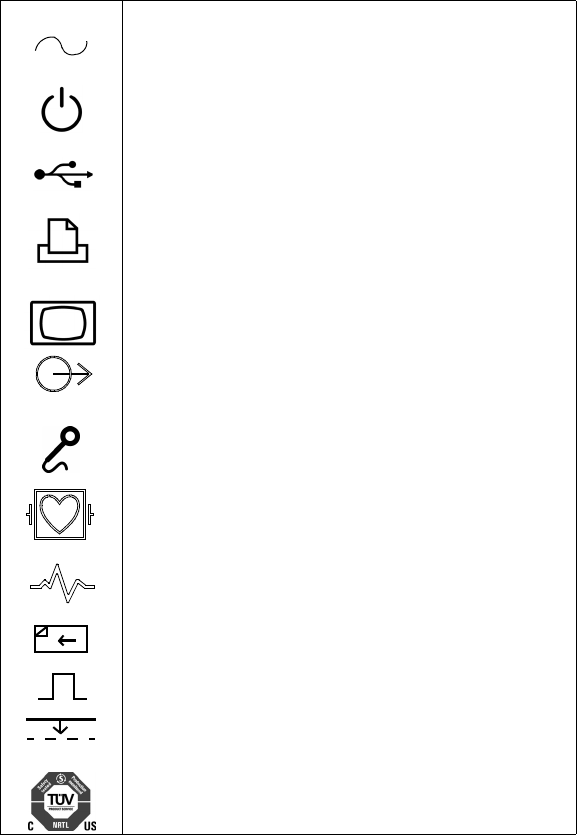
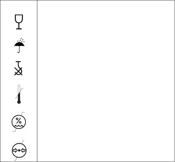
LABEL SYMBOLS
Table 3 illustrates the symbols used on the Model 3120 PRM and
includes an explanation of each symbol.
Table 3. Label Symbols and Their Meanings
Symbol Meaning
Alternating current
On/Off button
USB
Parallel connector for printer
VGA output for external monitor
Analog output
Telemetry wand input
Indicates defibrillator-proof CF-type patient
ECG cable connector
Paper form feed
Calibration pulse
Bring trace to baseline
Mark for nationally recognized testing for safety standards
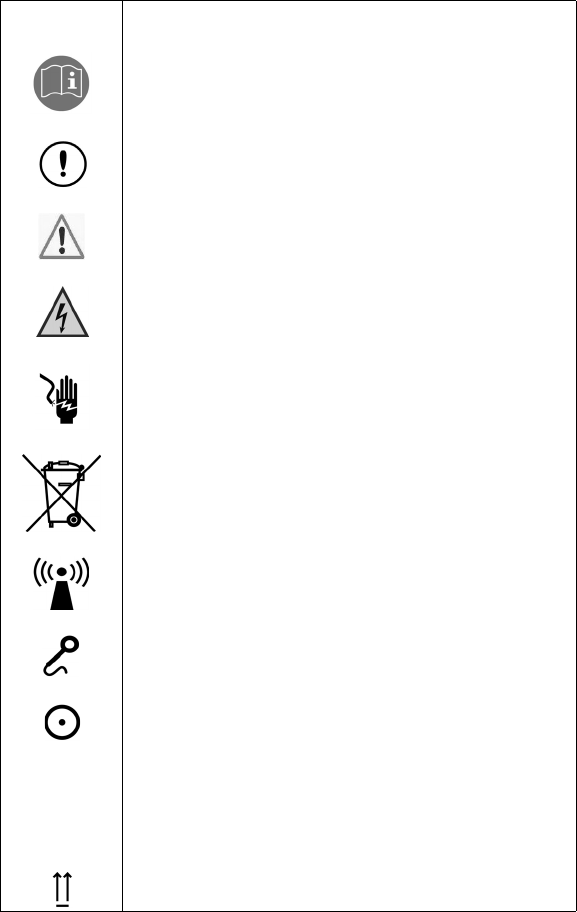
32
See instruction manual
Radio, Telecommunications and Terminal Equipment (RTTE)
symbol. Indicates that device does not operate in a
harmonized bandwidth
Attention (ECG and Telemetry connectors)
Dangerous voltage. Refer servicing to Guidant
Indicates the risk of electric shock; do not remove the cover
(or back). Refer servicing to Guidant
Waste, Electrical, and Electronic Equipment (WEEE) symbol.
Indicates separate collection for electrical and electronic
equipment (i.e., do not throw this device in the trash)
ZIP telemetry indicator light
Inductive telemetry indicator light
On indicator light
VVoltage
S/N Serial number
A/N Assembly number
This side up
Table 3. Label Symbols and Their Meanings
Symbol Meaning
33
Fragile, handle with care
Keep dry
Do not use hooks
Temperature limitations
Humidity limitations
Atmospheric pressure limitations
Table 3. Label Symbols and Their Meanings
Symbol Meaning

34
SAFETY AND ELECTROMAGNETIC
COMPATIBILITY COMPLIANCE STANDARDS
This equipment complies with the safety, electromagnetic compatibility
(EMC), and medical safety requirements.
Safety Standards
This equipment has been tested and found to comply with applicable
safety portions of the following standards:
• EN 60601-1:1990 + A1:1993 + A2:1995
• UL 60601-1:2003
• CAN/CSA-C22.2 No. 601.1-M90
Electromagnetic Compability Standards
This equipment has been tested and found to comply with the applicable
portions of the electromagnetic compatibility (EMC) standards:
• FCC Part 15.209:2004 + 15.207:2004 + 15.249:2004
• EN 300 330-2 V1.1.1:2000
• EN 300 220-1 V1.3.1:2000
• EN 301 489-1 V1.4.1:2002
NOTES:
• Use special precautions regarding EMC during the installation and
the use of the Model 3120 PRM, according to the EMC instructions
given throughout this manual. Table 4 on page 36 and Table 5 on
page 37 provide details about the PRM’s electromagnetic
emissions and immunity.
• Use caution when using RF portable and mobile equipment in
close proximity to the Model 3120 PRM. Table 6 on page 38 and
Table 7 on page 39 provide details about the PRM’s
electromagnetic immunity.
Medical Device Directive
This equipment has been tested and found to comply with the applicable
limits for medical devices to IEC 60601-1-2:2001 [or EN 60601-1-2:2001
or Medical Device Directive 93/42/EEC]. This testing shows the device
provides reasonable protection against harmful interference in a typical
medical installation. However, there is no guarantee that interference will
not occur in a particular installation. If this equipment does cause harmful
interference to other devices or is negatively impacted by other devices,
the user is encouraged to try to correct the interference by one or more of
the following measures:
• Reorient or relocate the devices.
• Increase the separation between the devices.
• Connect the equipment to an outlet on a different circuit.
• Consult the manufacturer or field service technician for help.
These
notes
belong
with the
EMC
section,
not the
MDD
section.

35
The PRM is capable of continuous operation and will not shut off
automatically if it is unused for an extended time or if it runs out of paper.
Keep the air intake and outlet free from obstruction.
CAUTION: The PRM is not water-proof or explosion-proof. It should not
be used in the presence of flammable gas mixtures including
anesthetic mixture with air, oxygen, or nitrous oxide.
NOTES:
•Use special precautions regarding EMC during the installation and
the use of the Model 3120 PRM, according to the EMC instructions
given throughout this manual. Table 4 on page 36 and Table 5 on
page 37 provide details about the PRM’s electromagnetic
emissions and immunity.
•Use caution when using RF portable and mobile equipment in
close proximity to the Model 3120 PRM. Table 6 on page 38 and
Table 7 on page 39 provide details about the PRM’s
electromagnetic immunity.
Federal Communications Commission (FCC)
This device complies with Title 47, Part 15, of the FCC rules. Operation is
subject to the following two conditions:
1. This device may not cause harmful interference, and
2. This device must accept any interference received, including
interference that may cause undesired operation.
CAUTION: Changes or modifications not expressly approved by Guidant
could void the user’s authority to operate the equipment.
These
sections
moved to more
appropriate
locations.
Changed to
subhead that
now falls
under the
Compliance
Standards
section

36
ELECTROMAGNETIC EMISSIONS AND IMMUNITY
Table 4. Guidance and Manufacturer’s Declaration – Electromagnetic
Emissions – for all Equipment and Systemsa
a. The Model 3120 PRM is intended for use in the electromagnetic environment specified
above. The customer or the user of the Model 3120 PRM should assure that it is used in
such an environment.
Emissions test Compliance Electromagnetic environment –
guidance
RF emissions (CISPR 11) Group 1
The Model 3120 PRM uses RF energy only for its
internal function. Therefore, its RF emissions are
very low and are not likely to cause any
interference in nearby electronic equipment.
RF emissions (CISPR 11) Class A
The Model 3120 PRM is suitable for use in all
establishments other than domestic and those
directly connected to the public low-voltage
power supply network that supplies buildings
used for domestic purposes.
Harmonic emissions
(IEC 61000-3-2) Class A
Voltage fluctuations/flicker
emissions (IEC 61000-3-3) Complies

37
Table 5. Guidance and Manufacturer’s Declaration – Electromagnetic
Immunity – for all Equipment and Systemsa
a. The Model 3120 PRM is intended for use in the electromagnetic environment specified
above. The customer or the user of the Model 3120 PRM should assure that it is used in
such an environment.
Immunity test IEC 60601
test level
Compliance
level
Electromagnetic
environment – guidance
Electrostatic discharge
(ESD) (IEC 61000-4-2)
±6 kV contact
±8 kV air
±6 kV contact
±8 kV air
Floors should be wood,
concrete, or ceramic tile. If
floors are covered with
synthetic material, the relative
humidity should be at least
30 percent.
Electrical fast transient/
burst (IEC 61000-4-4)
±2 kV for power-
supply lines
±1 kV for input/
output lines
±2 kV for power-
supply lines
±1 kV for input/
output lines
Mains power quality should be
that of a typical commercial or
hospital environment.
Surge (IEC 61000-4-5)
±1 kV differential
mode
±2 kV common
mode
±1 kV differential
mode
±2 kV common
mode
Mains power quality should be
that of a typical commercial or
hospital environment.
Voltage dips, short
interruptions, and voltage
variations on power-
supply input lines
(IEC 61000-4-11)
<5% UTb
(>95% dip in UT)
for 0.5 cycle
40% UT
(60% dip in UT)
for 5 cycles
70% UT
(30% dip in UT)
for 25 cycles
<5% UT
(>95% dip in UT)
for 5 sec
b. UT is the AC mains voltage prior to application of the test level.
<5% UT
(>95% dip in UT)
for 0.5 cycle
40% UT
(60% dip in UT)
for 5 cycles
70% UT
(30% dip in UT)
for 25 cycles
<5% UT
(>95% dip in UT)
for 5 sec
Mains power quality should be
that of a typical commercial or
hospital environment. If the
user of the Model 3120 PRM
requires continued operation
during power mains
interruptions, it is
recommended that the
Model 3120 PRM be powered
from an uninterruptible power
supply or a battery.
Power frequency
(50/60 Hz) magnetic field
(IEC 61000-4-8)
3 A/m 3 A/m
Power frequency magnetic
fields should be at levels
characteristic of a typical
location in a typical commercial
or hospital environment.
38
Table 6. Guidance and Manufacturer’s Declaration – Electromagnetic
Immunity – for Equipment and Systems That are not Life-Supportinga, b, c
a. The Model 3120 PRM is intended for use in the electromagnetic environment specified
above. The customer or the user of the Model 3120 PRM should assure that it is used in
such an environment.
b. At 80 MHz and 800 MHz, the higher frequency range applies.
c. These guidelines may not apply in all situations. Electromagnetic propagation is affected by
absorption and reflection from structures, objects, and people.
Immunity test IEC 60601
test level
Compliance
level
Electromagnetic environment
– guidance
Portable and mobile RF
communications equipment should be
used no closer to any part of the
Model 3120 PRM, including cables,
than the recommended separation
distance calculated from the equation
applicable to the frequency of the
transmitter.
Recommended separation distance
Conducted RF
(IEC 61000-4-6)
3Vrms
150 kHz to 80 MHz 3V
Radiated RF
(IEC 61000-4-3)
3V/m
80 MHz to 2.5 GHz 3V/m
where P is the maximum output power
rating of the transmitter in watts (W)
according to the transmitter
manufacturer and d is the
recommended separation distance in
meters (m).
Field strengths from fixed RF
transmitters, as determined by an
electromagnetic site survey,d should
be less than the compliance level in
each frequency range.e
Interference may occur in the vicinity
of equipment marked with the
following symbol:
d. Field strengths from fixed transmitters, such as base stations for radio (cellular/cordless)
telephones and land mobile radios, amateur radio, AM and FM radio broadcast, and TV
broadcast cannot be predicted theoretically with accuracy. To assess the electromagnetic
environment due to fixed RF transmitters, an electromagnetic site survey should be
considered. If the measured field strength in the location in which the Model 3120 PRM is
used exceeds the applicable RF compliance level above, the Model 3120 PRM should be
observed to verify normal operation. If abnormal performance is observed, additional
measures may be necessary, such as reorienting or relocating the Model 3120 PRM.
e. Over the frequency range 150 kHz to 80 MHz, field strengths should be less than 3 V/m.
d1.17 P=
d1.17 P=(80MHz to 800MHz)
d2.33 P=(800 MHz to 2.5 GHz)

39
Table 7. Recommended Separation Distances between Portable and Mobile
RF Communications Equipment and the Model 3120 PRMa, b, c, d
a. The Model 3120 PRM is intended for use in an electromagnetic environment in which
radiated RF disturbances are controlled. The customer or the user of the Model 3120 PRM
can help prevent electromagnetic interference by maintaining a minimum distance between
portable and mobile RF communications equipment (transmitters) and the Model 3120 PRM
as recommended above, according to the maximum output power of the communications
equipment.
b. For transmitters rated at a maximum output power not listed above, the recommended
separation distance d in meters (m) can be estimated using the equation applicable to the
frequency of the transmitter, where P is the maximum output power rating of the transmitter
in watts (W) according to the transmitter manufacturer.
c. At 80 MHz and 800 MHz, the separation distance for the higher frequency range applies.
d. These guidelines may not apply in all situations. Electromagnetic propagation is affected by
absorption and reflection from structures, objects, and people.
Rated maximum
output power of
transmitter
W
Separation distance according to frequency of transmitter
m
150 kHz to
80 MHz
80 MHz to
800 MHz
800 MHz to
2.5 GHz
0.01 0.12 0.12 0.23
0.1 0.370.370.74
1 1.171.172.33
10 3.70 3.70 7.38
100 11.70 11.70 23.33
d1.17 P=d1.17 P=d2.33 P=

40
SPECIFICATIONS (Nominal)
Table 8. Nominal Specifications
Safety classification Class I, Type CF, Defibrillation protected
Dimensions 18.5 in (47 cm) deep, 14.5 in (36.8 cm) wide,
4.75 in (12.1 cm) high
Weight (approximate) 21.5 lb (9.8 kg)
Power rating 100–240 V, 50/60 Hz, 3.8/1.9 A
Power cord
8 ft (2.4 m), 100–240 V. Reliable grounding is
achieved only when equipment is connected
to receptacle marked with “Hospital only” or
“Hospital grade.”
Operating temperature 50°F to 105°F (10°C to 35°C)
Transport and storage
temperature –40°F to 160°F (–40°C to 70°C)
Operating, transport, and
storage humidity 25% to 95%
Atmospheric pressure 7.252 psi to 15.374 psi (50 kPa to 106 kPa)
External printer support DB 25 parallel port connector
External monitor support DB 15 VGA port connector
Analog output + 1 V output via seven-pin DIN connector
ECG performance
• Minimum amplitude
detected 4.56 µV
• Lead selection I, II, III, aVR, aVL, aVF, V
• Intrinsic ventricular rate
display 30 bpm to 240 bpm + 6 bpm
• Input impedance > 2.5 M Ω
• Electrode offset tolerance 300 mV
• Storage resolution 800 samples/sec, 4.56 µV
• Filter settings ON: 0.5 Hz to 25 Hz, + 0.2 dB;
OFF: 0.05 Hz to 100 Hz, + 0.2 dB
• Gain settings 1, 2, 5, 10, 20 mm/mV + 25%
Wanded telemetry
• Frequency Transmit: 69 kHz
Receive: 0–100 kHz
• Bandwidth 100 kHz
• Modulation OOK
• Effective radiated power –1.2 dBµV/m
ZIP telemetry

41
• Frequency band ISM (902 to 928 MHz)
• Bandwidth < 1 MHz
• Modulation ASK/OOK
• Effective radiated power –1.3 dBm
Internal printer
• Paper type Thermo-sensitive
• Paper width 4 in (110 mm)
• Chart speed 10, 25, 50, 100 mm/sec
Battery type DL 2450 or equivalent
Safety features
• Leakage current < 10 µA (patient); < 100 µA (chassis)
• Defibrillator protection to 5,000 V, 400 J
42

Guidant Corporation
4100 Hamline Avenue North
St. Paul, MN 55112-5798 USA
Tel: 651.582.4000 Fax: 651.582.4166
Medical Professionals: 1.800.CARDIAC (227.3422) Toll Free
Patients and Families: 1.866.GUIDANT (484.3268) Toll Free
www.guidant.com
© 2005 Guidant Corporation
All rights reserved. 357043-001 A US 02/05
FCC ID: ESCCRM312005
*357043-001*