Boston Scientific CRM330017 3300 User Manual
Boston Scientific Corporation 3300
UserManual.wiki
>
Boston Scientific
>
CRM330017 User Manual
User Manual
Navigation menu
Upload a User Manual
Namespaces
Wiki Guide
HTML
PDF
Info
Views
User Manual
Discussion / Help
Navigation


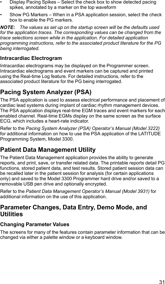
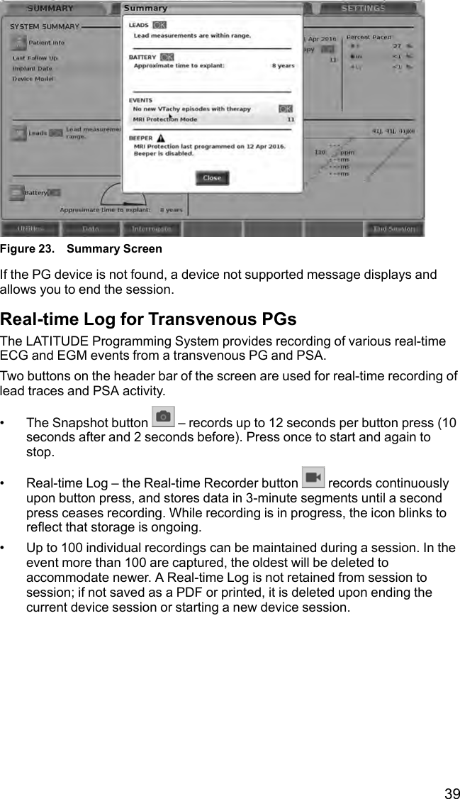
![15[1] Model 3300 Programmer [2] Stand Clip [3] Model 6755 Stand [4] storage pocketFigure 1. Optional Stand for the LATITUDE Programming SystemCAUTION: The power adapter normally gets warm when it is in use orcharging. Do not place the power adapter in the storage pocket of the standwhile it is in use or charging as the confined space will not allow the heat todissipate adequately.External PrinterThe LATITUDE Programming System supports a broad range of external USB2.0 and USB 3.0 printers. Refer to "Connections" on page 16 to connect theprinter’s USB cable.Some Bluetooth®printers are also supported. Refer to the Network andConnectivity Operator’s Manual (Model 3924) for additional setup and useinformation.USB Grounding Plug and CableA USB grounding plug and cable may be used with the Model 3300Programmer to provide an earth ground to decrease noise interference to theLATITUDE Programming System. Contact your hospital/clinic biomedicalengineering department for this standard piece of equipment.WARNING:The use of any cables or accessories with the LATITUDE ProgrammingSystem other than those provided by or specified by Boston Scientific couldresult in increased electromagnetic emissions, decreased electromagneticimmunity, or electrical shock of the LATITUDE Programming System. Anyoneconnecting such cables or accessories to the LATITUDE ProgrammingSystem, including the use of MSOs (Multiple Socket Outlets), may beconfiguring a medical system and is responsible to ensure that the systemcomplies with the requirements of IEC/EN 60601-1, Clause 16 for medicalelectrical systems.](https://usermanual.wiki/Boston-Scientific/CRM330017/User-Guide-3439790-Page-21.png)
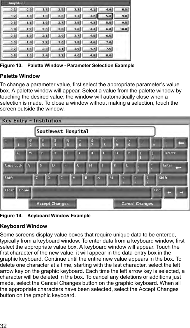
![17Patient Side Panel (Right Side)[1] Model 6763 PSA Cable for LV (green) [2] Model 6763 PSA Cable for A/RV (light gray) [3] Model3153 ECG Cable (dark gray) [4] connection port for future use (brown) [5] Model 3203 S-ICDTelemetry Wand (black) [6] Model 6395 Telemetry Wand (blue)Figure 2. Right Side Panel of the ProgrammerPhysician Side Panel (Left Side)NOTE: Equipment connected to the external connections must comply withapplicable standards for data processing equipment and for medicalequipment.[1] Power (on/off) button (light gray) [2-4] USB 2.0 ports (dark gray) [5] USB 3.0 port (blue) [6]Ethernet port (orange) [7] DisplayPort Out (red-orange) [8] DC power connection for Model 6689power adapter (green)Figure 3. Left Side Panel of the Programmer](https://usermanual.wiki/Boston-Scientific/CRM330017/User-Guide-3439790-Page-23.png)
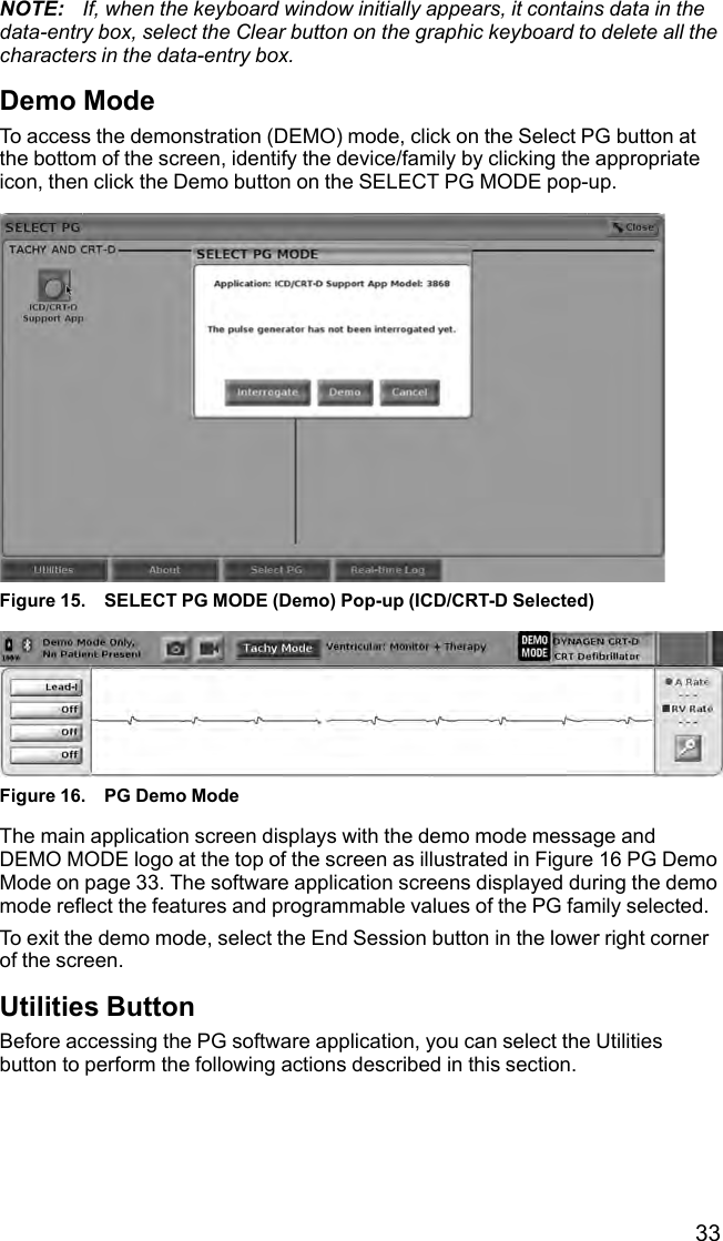
![18Indicator LightsThe Programmer has an indicator light on the left side of the device containedwithin the power (on/off) button . The Model 6395 Telemetry Wand has anindicator light on the front face. The functions are described below.•Power (on/off) button is lit when the Programmer is on.• The light on the Model 6395 Telemetry Wand illuminates to indicate thatinductive telemetry is established and is actively communicating to a PG.STAT ButtonThe Programmer has a red STAT button on the front top-right of thedevice. Depending on the situation, the STAT function provides STAT PACE,STAT SHOCK, or DIVERT THERAPY.[1] Red STAT buttonFigure 4. Front View of LATITUDE Programming System Indicating the Red STATButton LocationUSING THE LATITUDE PROGRAMMING SYSTEMPreparation for UseBattery Charge Level and ChargingThe Lithium-ion battery for the Programmer is not charged when shipped. Tocharge the battery, perform the following steps.NOTE: Before using the battery with the LATITUDE Programming System,ensure that the battery is fully charged.1. Connect the AC power and turn on the Programmer. See Figure 3 LeftSide Panel of the Programmer on page 17.2. Check the battery charge by noting the battery status indicator in the upperleft of the screen, which displays the battery charge percent. See Figure 9Main Screen on page 25.3. Nominally, battery charging can take 1-2 hours when the battery is lessthan 30% charged.](https://usermanual.wiki/Boston-Scientific/CRM330017/User-Guide-3439790-Page-24.png)
![20[1] Model 6763 PSA Cable for LV (green) [2] Model 6763 PSA Cable for A/RV (light gray) [3] Model3153 ECG Cable (dark gray) [4] connection port for future use (brown) [5] Model 3203 S-ICDTelemetry Wand (black) [6] Model 6395 Telemetry Wand (blue)Figure 5. Right Side (Patient) Panel1. For PSA measurements, connect the appropriate PSA cable to theappropriate connector (LV or A/RV).2. Connect the appropriate telemetry wand to its connector:• Model 6395 Telemetry Wand• Model 3203 S-ICD Telemetry WandNOTE: Under battery-operated power with wanded telemetry, theLATITUDE Programming System is able to communicate with the PGbeneath the patient’s skin. For most pectoral implants, the telemetry issufficient to communicate with the PG. For abdominal implants, thedistance may be greater and battery-operated power only may not besufficient to maintain reliable communication. To achieve maximuminductive telemetry communication with the PG, always use externalpower.3. Connect the surface ECG patient cable to the ECG connector. Attach thesurface electrodes to the patient in a standard three-wire or five-wireconfiguration.NOTE: The ECG function may be sensitive to high-frequency ambientnoise when the ECG inputs are not attached. If the electrodes are notattached to the patient, they may be sensitive to high-frequencyenvironmental noise and therefore provide a poor signal. The ECG surfacetraces can be turned off if excessive noise is present.NOTE: The ECG function is intended to be used during patient exams fortests such as pace threshold testing.NOTE: The ECG function may exhibit noise interference if theLATITUDE Programming System is in close proximity to high-frequencyelectrosurgical equipment. For corrective action, refer to "Troubleshooting"on page 52.4. If MICS or RF telemetry is insufficient, connect the Model 3203 S-ICDTelemetry Wand to its connector. The S-ICD telemetry wand acts as anextra RF antenna. Orient this wand as necessary to improve RF telemetry](https://usermanual.wiki/Boston-Scientific/CRM330017/User-Guide-3439790-Page-26.png)
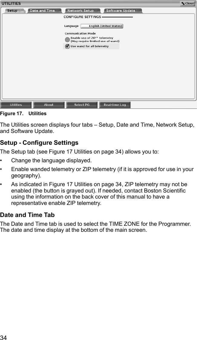
![21performance. Refer to "Steps to Improve ZIP (RF) Telemetry Performance"on page 23 for additional information.Make Physician Side ConnectionsAs needed, make the following connections on the left side of the LATITUDEProgramming System.[1] Power (on/off) button (light gray) [2-4] USB 2.0 ports (dark gray) [5] USB 3.0 port (blue) [6]Ethernet port (orange) [7] DisplayPort out (red-orange) [8] DC power connection for Model 6689Power Adapter (green)Figure 6. Left Side (Physician) Panel1. Connect the power cord to the DC receptacle on the left side panel of theProgrammer.2. To connect an external USB printer, attach the appropriate USB cable (2.0or 3.0) to the appropriate USB port on the Programmer. Then, ensure thatthe printer is connected to external power.NOTE: Connect the printer to the USB port, then wait 30 seconds for thesystem to recognize the printer before sending files to the printer.NOTE: The LATITUDE Programming System has Bluetooth®capability,which can be used to connect with Bluetooth®capable printers.3. Use the DisplayPort Out connector to attach an external monitor. Then,ensure that the monitor is connected to external power.4. To connect to a LAN, attach an Ethernet cable to the Ethernet port.NOTE: Connect the Ethernet cable only to the RJ45 Ethernet portconnector on the Model 3300 Programmer.NOTE: Additional steps need to be completed when using Bluetooth®orLAN communications. Refer to the Network and Connectivity Operator’sManual (Model 3924) for additional information.5. Ensure the power adapter cable is plugged into the DC port on the left sideof the Programmer and the power cord is plugged into the power adapter.NOTE: Ensure the left side of the device is accessible at all times so thatthe power cord can be connected and disconnected.](https://usermanual.wiki/Boston-Scientific/CRM330017/User-Guide-3439790-Page-27.png)
![23[1] Internal antenna locations, approximateFigure 8. Front View of LATITUDE Programming System Indicating ApproximateAntenna Locations Within the EnclosureSteps to Improve ZIP (RF) Telemetry PerformancePerform the following to increase RF telemetry performance:1. Disconnect all unused cables and wands and stow them.2. All remaining connected patient side cables (PSA, ECG) should exitperpendicular to the Programmer and (as much as possible) directlytoward the patient.3. All remaining connected physician side cables (power, USB, DisplayPort,Ethernet) should be routed away from the patient.4. If there are any electrical equipment (laptop, monitor, etc.) or metal objectsadjacent to the Programmer, move them away from the Programmer asmuch as possible.5. Move the Programmer closer to the patient, ideally away from a busy orcrowded location in the room.6. Change the Programmer orientation by rotating the Programmer up to 45degrees clockwise or counter-clockwise or by placing the Programmer intothe optional Model 6755 Stand.7. Ensure that clinic staff are not in the line of sight between the Programmerand the implanted PG.8. If telemetry is still not consistent, attach the Model 3203 S-ICD TelemetryWand and place it within 0.6 m (2 ft) of the implanted PG. In the sterilefield, use a Model 3320 Intraoperative Probe Cover and place the wand ontop of the patient’s stomach.• When not used for RF telemetry, be sure to disconnect the Model3203 S-ICD Telemetry Wand from the Programmer to preventtelemetry dropouts.9. If ZIP telemetry is not successful for a PG capable of RF telemetry, use theModel 6395 Telemetry Wand to interrogate the PG.](https://usermanual.wiki/Boston-Scientific/CRM330017/User-Guide-3439790-Page-29.png)
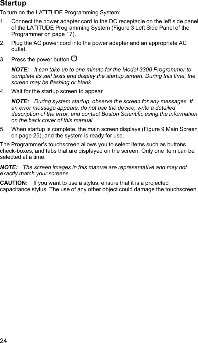
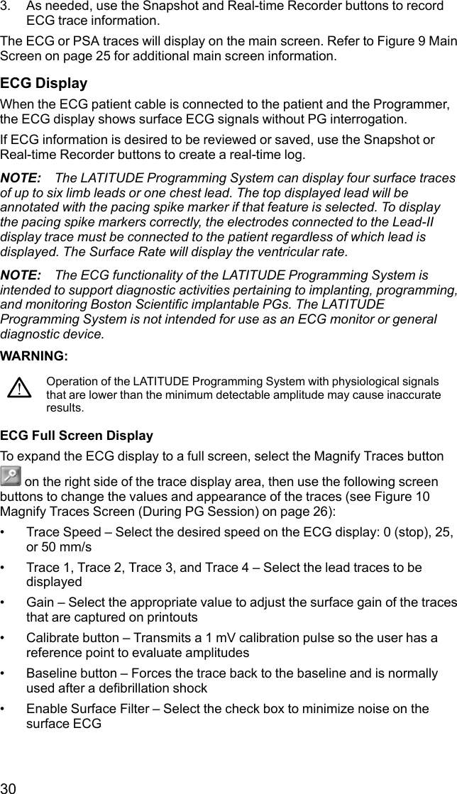
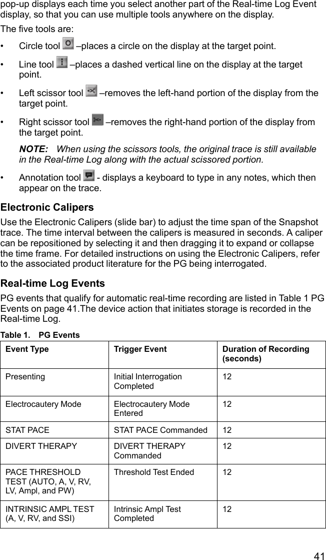
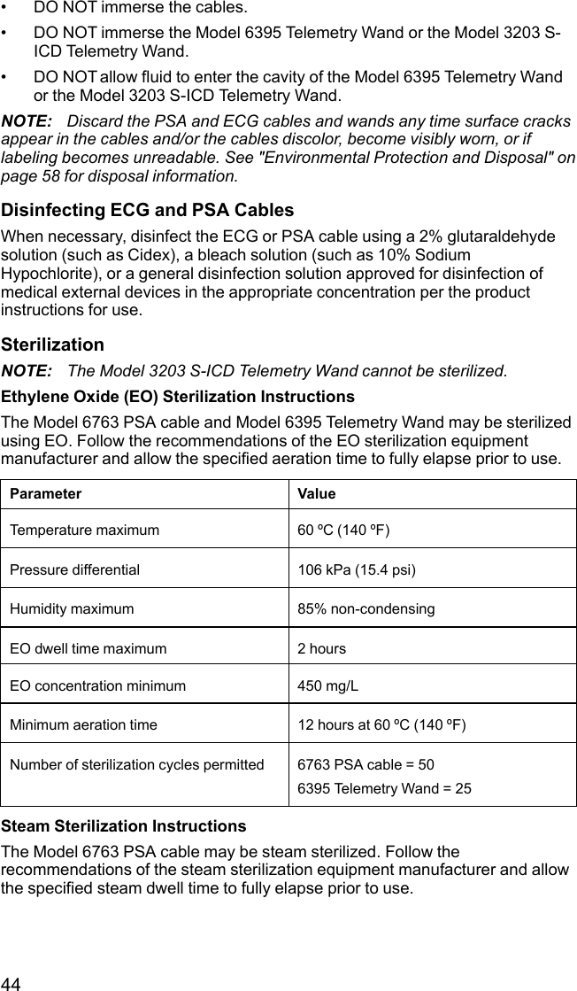
![25[1] Battery status, Ethernet, and Bluetooth®indicators [2] ECG and EGM lead trace selections, up tofour [3] lead trace display area [4] Snapshot button [5] Real-time Recorder button [6] PSA applicationbutton [7] Magnify Traces button [8] Quick Start button [9] Patient Data Management buttonFigure 9. Main ScreenWhen the LATITUDE Programming System is powered on, a Start Applicationwindow displays a progress bar as the software loads. Normally this takes up toone minute. When complete, the main screen displays the following asillustrated in Figure 9 Main Screen on page 25:• The status area displays battery charge status and Wi-Fi, Ethernet, andBluetooth®connectivity indicators• The lead trace display, which can show up to four lead traces for patientassessment such as from a surface ECG or a PSA• There are two buttons (Snapshot and Real-time Recorder ) at thetop of the screen for capturing real-time recordings of lead traces duringECG, PG, and PSA activity• The PSA button activates the PSA application (see "Pacing SystemAnalyzer (PSA)" on page 31)• The Quick Start button initiates PG communication to read a specificPG application](https://usermanual.wiki/Boston-Scientific/CRM330017/User-Guide-3439790-Page-31.png)
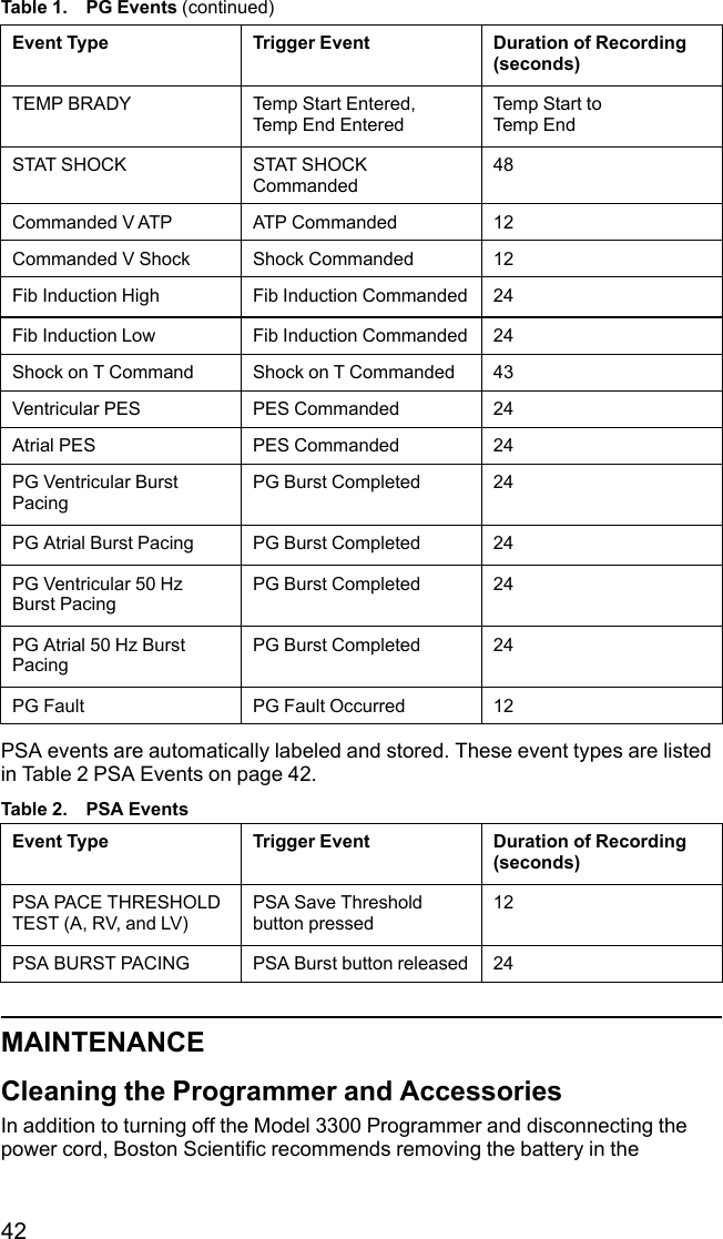
![40Figure 24. Real-time Log – List Screen[1] Notes area [2] Real-time Log Tools pop-up [3] Electronic Calipers (slide bar) to adjust time span ofevent [4] Real-time Log Event displayFigure 25. Real-time Log – Event Trace ExampleThe Notes button in the Notes area can be used to add comments. A Real-timeLog can be customized using the tools in the Real-time Log Tools pop-up. TheElectronic Calipers at the bottom of the screen can be adjusted to measure thedesired time span.Real-time Log ToolsSelect any part of the Real-time Log Event display, and the Tools pop-updisplays as in Figure 25 Real-time Log – Event Trace Example on page 40. Atthe top center of the pop-up is an arrow and a target icon. When a tool isselected, the tool action occurs at that target point on the screen. A new Tools](https://usermanual.wiki/Boston-Scientific/CRM330017/User-Guide-3439790-Page-46.png)
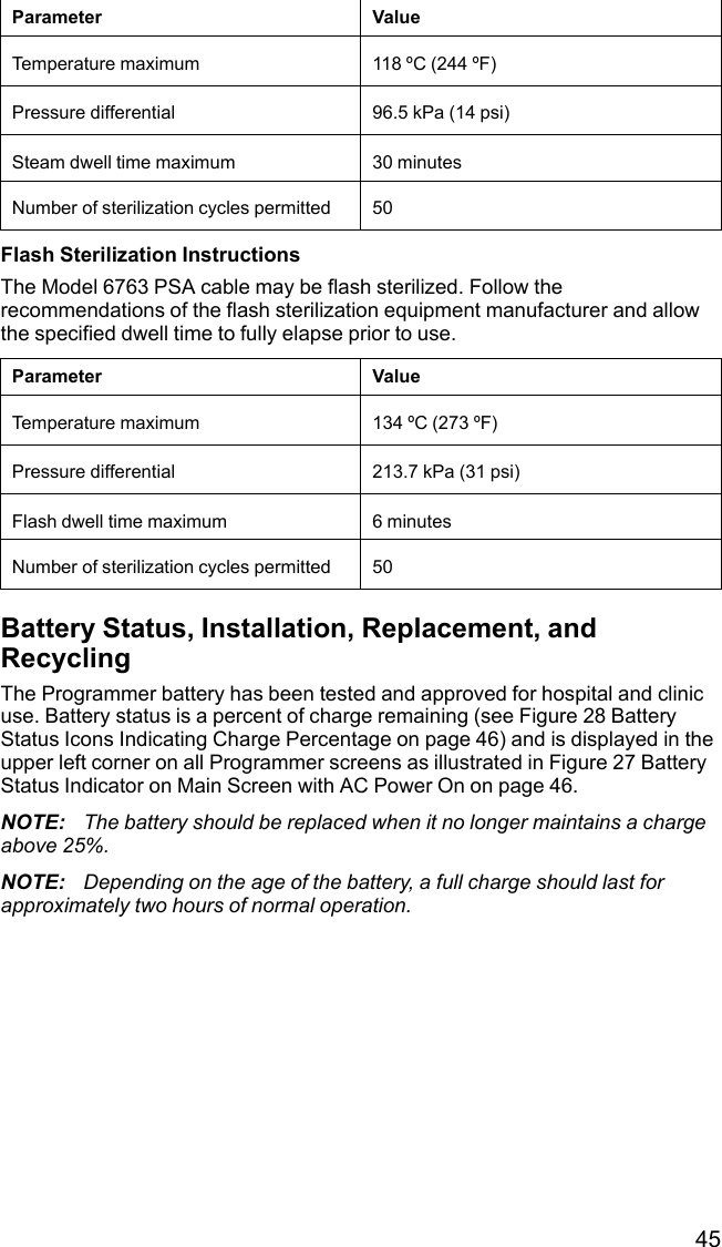
![47[1] Battery release button [2] Direction to slide cover for removal (reverse the direction to replace thecover)Figure 30. Battery Compartment on Underside of the Programmer[1] Battery lift out tab [2] Battery retaining strap [3] Battery status indicator LEDs [4] Battery connectorterminals (partially hidden)Figure 31. Replaceable Programmer Battery](https://usermanual.wiki/Boston-Scientific/CRM330017/User-Guide-3439790-Page-53.png)


![57• Model 6395 Telemetry Wand[1] Model 3153 ECG cable, [2] ECG monitor, [3] ECG-BNC slave cable, [4] Programmer ECGconnector, [5] Programmer Model 6395 Telemetry Wand connector, [6] Model 6395 Telemetry Wand,[7] LATITUDE Programming System (right side view)Figure 32. External ECG Monitor ConfigurationTo display a tracing on an external ECG monitor and the Programmer, set upequipment as shown in Figure 32 External ECG Monitor Configuration on page57.In the example in Figure 32 External ECG Monitor Configuration on page 57,the surface ECG signal travels the following route:1. Model 3153 Fixed Patient Leads ECG cable2. External ECG monitor3. ECG-BNC slave cable4. Programmer ECG connector5. Programmer Model 6395 Telemetry Wand connector6. Model 6395 Telemetry Wand](https://usermanual.wiki/Boston-Scientific/CRM330017/User-Guide-3439790-Page-63.png)

![62• EN 300 220-2 V2.4.1:2012• EN 301 489-1 V1.9.2:2011• EN 301 489-3 V1.6.1:2013• EN 301 489-17 V2.2.1 2012• EN 301 489-27 V1.1.1 2004• EN 301 489-31 V1.1.1 2005NOTE: Use special precautions regarding EMC during the installation and theuse of the LATITUDE Programming System, according to the EMC instructionsgiven throughout this manual. Refer to the details about the LATITUDEProgramming System electromagnetic emissions and immunity in Table 6LATITUDE Programming System Nominal Specifications on page 66 and Table7 Radio Nominal Specifications on page 68.NOTE: Use caution when using RF portable and mobile telephony equipmentin close proximity to the LATITUDE Programming System. Refer to the detailsabout the LATITUDE Programming System electromagnetic immunity in Table8 Network and Connectivity Specifications on page 69.Electromagnetic Emissions and ImmunityIEC 60601–1–2:2014 InformationThis equipment has been tested and found to comply with the applicable limitsfor Class A medical devices in a professional healthcare facility environment toANSI/AAMI/IEC 60601-1-2:2014 [or BS EN 60601-1-2:2015 or ActiveImplantable Medical Device Directive 90/385/EEC]. This testing shows thedevice provides reasonable protection against harmful interference in a typicalmedical installation. However, there is no guarantee that interference will notoccur in a particular installation.Federal Communications Commission (FCC) InformationThis device complies with Title 47, Part 15 of the FCC rules. Operation issubject to the following two conditions:• This device may not cause harmful interference.• This device must accept any interference received, including interferencethat may cause undesired operation.This transmitter is authorized by rule under the Medical DeviceRadiocommunication Service (in part 95 of the FCC Rules) and must not causeharmful interference to stations operating in the 400.150-406.000 MHz band inthe Meteorological Aids (i.e., transmitters and receivers used to communicateweather data), the Meteorological Satellite, or the Earth Exploration SatelliteServices and must accept interference that may be caused by such stations,including interference that may cause undesired operation. This transmittershall be used only in accordance with the FCC Rules governing the MedicalDevice Radiocommunication Service. Analog and digital voice communicationsare prohibited. Although this transmitter has been approved by the FederalCommunications Commission, there is no guarantee that it will not receive](https://usermanual.wiki/Boston-Scientific/CRM330017/User-Guide-3439790-Page-68.png)