Boston Scientific CRM330017 3300 User Manual
Boston Scientific Corporation 3300
User Manual

OPERATOR’S MANUAL
LATITUDE™
PROGRAMMING
SYSTEM
Model 3300
CAUTION: Federal law (USA) restricts
this device to sale by or on the order of a
physician trained or experienced in
device implant and follow-up
procedures.
Table of Contents
INFORMATION FOR USE ...................................................................1
Trademark Statement .......................................................................1
Description and Use .........................................................................1
Intended Use ................................................................................1
Intended Audience .........................................................................1
Required Expertise and Knowledge ...................................................1
Essential Performance ....................................................................2
Contraindications.............................................................................2
Warnings........................................................................................3
Precautions ....................................................................................7
Adverse Effects ............................................................................. 11
SYSTEM CAPABILITIES .................................................................. 11
Hardware ..................................................................................... 11
Interrogation and Programming ......................................................... 12
Patient Data Management ............................................................... 12
Networking ................................................................................... 13
Software ...................................................................................... 13
SYSTEM ACCESSORIES ................................................................. 13
Optional External Equipment ............................................................ 14
Stand ........................................................................................ 14
External Printer............................................................................ 15
USB Grounding Plug and Cable ...................................................... 15
External Display........................................................................... 16
CONNECTIONS.............................................................................. 16
Patient Side Panel (Right Side) ......................................................... 17
Physician Side Panel (Left Side)........................................................ 17
Indicator Lights.............................................................................. 18
STAT Button.................................................................................. 18
USING THE LATITUDE PROGRAMMING SYSTEM ............................... 18
Preparation for Use ........................................................................ 18
Battery Charge Level and Charging ................................................. 18
Prepare a Telemetry Wand............................................................. 19
Cable Connections....................................................................... 19
Make Patient Side Connections....................................................... 19
Make Physician Side Connections ................................................... 21
Electrosurgical Cables .................................................................. 22
Prepare for ZIP (RF) Telemetry ....................................................... 22
Startup ........................................................................................ 24
PSA Button................................................................................. 27
Quick Start Button........................................................................ 27
Patient Data Management Button .................................................... 27
STAT Button for Transvenous PGs................................................... 27
Start a Transvenous PG Session ....................................................... 29
Quick Start (Button)...................................................................... 29
Select PG (Button) ....................................................................... 29
Surface ECG................................................................................. 29
ECG Display ............................................................................... 30
Intracardiac Electrogram................................................................ 31
Pacing System Analyzer (PSA) ......................................................... 31
Patient Data Management Utility ....................................................... 31
Parameter Changes, Data Entry, Demo Mode, and Utilities ..................... 31
Changing Parameter Values ........................................................... 31
Demo Mode.................................................................................. 33
Utilities Button ............................................................................... 33
Setup - Configure Settings ............................................................. 34
Date and Time Tab ....................................................................... 34
Network Setup Tab ....................................................................... 35
Software Update Tab .................................................................... 35
About Button................................................................................. 36
Selecting a PG .............................................................................. 37
Real-time Log for Transvenous PGs................................................... 39
Real-time Log Tools...................................................................... 40
Electronic Calipers ....................................................................... 41
Real-time Log Events.................................................................... 41
MAINTENANCE.............................................................................. 42
Cleaning the Programmer and Accessories ......................................... 42
Cleaning Cables and Wands .......................................................... 43
Disinfecting ECG and PSA Cables................................................... 44
Sterilization................................................................................. 44
Battery Status, Installation, Replacement, and Recycling........................ 45
Battery Replacement .................................................................... 48
Battery Recycling......................................................................... 49
Operation and Storage.................................................................... 49
Storing the LATITUDE Programming System ..................................... 50
Maintenance Check and Safety Measures ........................................... 51
LATITUDE Programming System Maintenance Check ......................... 51
Safety Measurements ................................................................... 51
Service ........................................................................................ 52
TROUBLESHOOTING...................................................................... 52
HANDLING .................................................................................... 56
Using an External ECG Monitor with the Model 3300
Programmer ............................................................................. 56
Environmental Protection and Disposal............................................. 58
Symbols on Devices and Packaging................................................. 58
SAFETY, COMPLIANCE, AND COMPATIBILITY STANDARDS................ 61
Safety Standards ........................................................................... 61
Electromagnetic Compatibility Standards ............................................ 61
Radio Spectrum Compliance Standards.............................................. 61
Electromagnetic Emissions and Immunity............................................ 62
IEC 60601–1–2:2014 Information .................................................... 62
Federal Communications Commission (FCC) Information ..................... 62
LATITUDE PROGRAMMING SYSTEM SECURITY ................................ 65
Software ...................................................................................... 65
Patient Data Management ............................................................... 65
Network ....................................................................................... 65
Unsupported Hardware ................................................................... 65
Security Vigilance .......................................................................... 65
Physical Controls ........................................................................... 65
Compromised Programmer .............................................................. 66
SPECIFICATIONS ........................................................................... 66
WARRANTY INFORMATION ............................................................. 70

1
INFORMATION FOR USE
Trademark Statement
The following are trademarks of Boston Scientific Corporation or its affiliates:
LATITUDE, Quick Start, and ZIP.
Bluetooth®is a registered trademark of Bluetooth SIG.
DisplayPort is a trademark of the Video Electronics Standards Association
(VESA).
Description and Use
Four separate Operator’s Manuals describe the LATITUDE Programming
System:
1. LATITUDE
™
Programming System Operator’s Manual (Model 3300)
2. Pacing System Analyzer (PSA) Operator’s Manual (Model 3922)
3. Patient Data Management Operator’s Manual (Model 3931)
4. Network and Connectivity Operator’s Manual (Model 3924)
These manuals are also available online at:
www.bostonscientific-elabeling.com.
The Model 3300 Programmer is the programming device of the LATITUDE
Programming System, which is a portable cardiac rhythm management system
designed to be used with specific Boston Scientific systems, i.e., implantable
pulse generators (PGs) and leads.
Intended Use
The LATITUDE Programming System is intended for use in hospital and clinical
environments to communicate with Boston Scientific implantable systems. The
software in use controls all communication functions for the PG. For detailed
software application instructions, refer to the associated product literature for
the PG being interrogated.
Intended Audience
The LATITUDE Programming System is intended for use by health care
professionals trained or experienced in device implant and/or follow-up
procedures.
Required Expertise and Knowledge
Users must be thoroughly familiar with electrotherapy of the heart. Only
qualified medical specialists having the special knowledge required for the
proper use of the device are permitted to use it.
Physician Supervision
The LATITUDE Programming System may only be operated under the constant
supervision of a physician. During a procedure, the patient must be
2
continuously monitored by medical personnel with the aid of a surface ECG
monitor.
Essential Performance
In order for the LATITUDE Programming System to meet its intended use, it
must communicate with Boston Scientific implantable PGs. Therefore those
functions that pertain to communications with the implanted PGs using
telemetry wands are considered essential performance.
LATITUDE Programming System performance determined to be essential by
Boston Scientific for electromagnetic compatibility testing, as per IEC 60601-1-
2, has the ability to:
• Interrogate and program a supported PG using wanded, inductive, and RF
telemetry
• Initiate a STAT PACE, PSA STAT PACE, STAT SHOCK, or DIVERT
THERAPY command to a PG where supported
• Display real-time intracardiac electrograms
• Supports touchscreen tap and button press interactions
• Deliver pacing and perform impedance lead measurements with the
Pacing System Analyzer (PSA) function
Boston Scientific hereby declares that this device is in compliance with the
essential requirements and other relevant provisions of Directive 1999/5/EC for
Radio and Telecommunications Terminal Equipment (RTTE). To obtain a full
text Declaration of Conformity, contact Boston Scientific using the information
on the back cover of this manual.
NOTE: No recurring calibration of the LATITUDE Programming System or its
applications is required or needed.
Contraindications
The LATITUDE Programming System is contraindicated for use with any PG
other than a Boston Scientific PG. For contraindications for use related to the
PG, refer to the associated product literature for the PG being interrogated.
The PSA application is contraindicated for use with any programming system
other than the Boston Scientific Model 3300 LATITUDE Programming System.
The following uses of the PSA are contraindicated:
• With AV conduction disorders; atrial single-chamber pacing
• With competing intrinsic rhythms; asynchronous modes
• With chronic atrial tachycardia as well as chronic atrial fibrillation or flutter;
modes with atrial control (DDD, VDD)
• With poor tolerance of high ventricular rates (e.g., with angina pectoris);
tracking modes (i.e., atrial control modes) and propensity for atrial
tachycardia
3
• Use as an external pacemaker1
WARNINGS
•Use of unspecified cables and accessories.
The use of any cables or accessories with the LATITUDE Programming
System other than those provided by or specified by Boston Scientific
could result in increased electromagnetic emissions, decreased
electromagnetic immunity, or electrical shock of the LATITUDE
Programming System. Anyone connecting such cables or accessories to
the LATITUDE Programming System, including the use of MSOs (Multiple
Socket Outlets), may be configuring a medical system and is responsible
to ensure that the system complies with the requirements of IEC/EN
60601-1, Clause 16 for medical electrical systems.
•Radio frequency (RF) communications equipment.
Keep all RF communications equipment (including peripherals such as
antennas, wands, and cables) at least 30 cm (12 in) away from the Model
3300 Programmer, including cables specified by Boston Scientific, to
avoid degradation of the performance of this equipment.
•Connector contacts.
Do not simultaneously touch the patient and any accessible LATITUDE
Programming System connector or exposed conductor.
•Electric shock.
To avoid the risk of electric shock, only connect the Programmer’s Model
6689 Power Adapter to a grounded/earthed power outlet.
•Battery access.
When accessing the battery, ensure that power to the Programmer is
turned off. Do not touch the connector terminals in the battery
compartment while removing or replacing the battery because an
electrical charge is present.
•Electrostatic charges.
The PSA lead system is in electrical contact with the patient’s heart and
blood.
• Do not touch the metal clips on the patient cable or the pacing lead.
Electrical currents can be dangerous to the patient and the user.
• Discharge any electrical static charge on your person by touching a
grounded metal surface before touching the patient, the patient
cables, or the device.
1. During implantation, the PSA application is suitable for temporary external pacing while the
patient is being continuously monitored by medical personnel.

4
•Electrical currents.
Unused PSA cable connections contacting conductive surfaces can
induce electrical currents into the patient’s heart.
• Attach unused cable connections to surgical draping near the patient
or disconnect the unused cables from the system.
•Electrocautery.
The LATITUDE Programming System is designed and tested to be
electrocautery safe.
• While the device is designed and tested to be electrocautery safe,
electrocautery can induce electrical currents in the PSA cables that
can be conducted into the patient’s heart. However, Boston Scientific
recommends that the Programmer be placed as far from the
electrocautery system and associated components as possible to
minimize noise being introduced into the LATITUDE Programming
System and patient cables.
• Never stack the Programmer on top of an electrocautery system or
associated components.
• Do not drape electrocautery components or cables on or near the
Programmer or associated cables and components.
• Whenever possible disconnect the PSA cables from the pacing leads
when performing an electrocautery procedure.
• If the Programmer is connected to the patient during an
electrocautery procedure, check its operation afterwards.
• If the Programmer experiences an issue that causes an error
condition, the Programmer will need to be power cycled. During the
reset and reboot, which takes up to one minute, there will be no
pacing support. For this reason, a backup PSA/pace resource must
be available in case electrocautery is applied.
•LATITUDE Programming System location.
Use of the PSA application on the Model 3300 Programmer adjacent to or
stacked with other equipment should be avoided because it could result in
improper operation. If such use is necessary, this equipment and the other
equipment should be observed to verify that they are operating normally.
•LATITUDE Programming System must remain outside sterile field.
The Programmer is non-sterile and cannot be sterilized. Do not allow the
device to enter a sterile zone in an implant environment.
•Physiological signals.
Operation of the LATITUDE Programming System with physiological
signals that are lower than the minimum detectable amplitude may cause
inaccurate results.
•LATITUDE Programming System is MR unsafe.

5
The LATITUDE Programming System is MR Unsafe and must remain
outside the MRI site Zone III (and higher) as defined by the American
College of Radiology Guidance Document for Safe MR Practices2. Under
no circumstances should the LATITUDE Programming System be brought
into the MRI scanner room, the control room, or the MRI site Zone III or IV
areas.
•Induction.
When activating PSA Burst Pacing, which may cause unpredictable
arrhythmias, always have cardiac emergency equipment (e.g., external
pacemaker, external defibrillator) in an operational status available for
immediate life support.
• Consider additional preemptive measures in patients where
acceleration or a loss of rhythm could cause life-threatening danger.
•External defibrillation.
The LATITUDE Programming System is designed and tested to be
defibrillation safe.
• While the Programmer is designed and tested to be defibrillation
safe, the patient can be endangered and the Programmer can be
damaged.
• The PSA cable must be disconnected from the lead(s) before using
external defibrillation.
• Whenever possible disconnect all cables from the patient when
using external defibrillation equipment.
• If the LATITUDE Programming System is connected to the patient
during defibrillation, verify that the Programmer is operating as
expected after defibrillation.
•External pacing equipment.
If the patient is pacer dependent and the Programmer encounters a fault
condition, pacing operation continues unless the fault was in the PSA
component itself. For this reason, always have external pacing equipment
available for patient back-up.
•Loss of power.
2. Kanal E, et al., American Journal of Roentgenology 188:1447-74, 2007.

6
Operating the Programmer with a depleted internal battery or no battery
can suspend Programmer function if AC power is temporarily interrupted.
• If an optional battery is used, do not use a depleted or unapproved
battery. For additional patient safety, when the battery level indicator
shows 25% or less remaining, connect the AC power to the
Programmer.
• When operating on battery power, do not attempt to replace the
battery.
• A yellow attention message displays on the Programmer screen
when the battery reaches 25% depletion. When the battery reaches
10% depletion or less, a red warning message displays. At 5%, there
is another red warning message followed by a 60–second automatic
shutdown.
•Loss of pacing support.
Always have external cardiac pacing equipment in an operational status
available for immediate life support.
• Initially, when the Programmer is switched on, the pacing functions
are switched off while a self-test is conducted. No pacing is possible
during the self-test, which can take up to one minute.
• Connecting the PSA cable to the wrong lead may result in ineffective
sensing and pacing behavior and loss of pacing support.
• If the user manually restarts the Programmer, pacing support is lost
until the system completes its self-test, which can take up to one
minute and the user must restart PSA manually if desired.
• If there is no battery installed, pacing support will be lost if AC power
is lost.
•Impaired AV conduction.
Single chamber atrial modes are contraindicated for patients with
impaired AV conduction.
• If the patient has impaired AV conduction, AAI programming and
antegrade conduction tests must not be performed.
•Abruptly terminating pacing.
Abruptly terminating pacing may result in extended periods of asystole in
some patients.
• Gradually decrease the pacing rate until the patient’s intrinsic rate is
detected for a controlled transition from pace to intrinsic rhythm.
•Loss of capture.
Pacing threshold testing implies loss of capture. At loss of capture,
asystole and pacing during vulnerable periods can occur.
• Consider the health of the patient prior to performing a pacing
threshold test.

7
•Use of protective sleeves.
Incorrect positioning of the protective silicone rubber sleeves over the
PSA cable clip(s) can cause unintended electrical connections that can
impair cable function and endanger the patient.
• Before connecting cables, ensure correct position of protective
sleeves.
•Do not use wet cables.
Moisture on wet cables can impair cable function and endanger the
patient.
•Exposure to fluids.
Before cleaning and disinfecting the Programmer surfaces, power down
the device and disconnect the external power supply. Before operating the
LATITUDE Programming System, let cleaning and disinfection agents
used on the Programmer evaporate.
•Emissions and interference.
The emissions characteristics of this equipment make it suitable for use in
industrial areas and hospitals (CISPR 11 class A). If it is used in a
residential environment (for which CISPR 11 class B is normally required),
this equipment might not offer adequate protection to radio-frequency
communication services. The user might need to take mitigation
measures, such as relocating or reorienting the equipment. Other
equipment may interfere with the LATITUDE Programming System, even
if that equipment complies with the CISPR emission requirements.
•Lithium-ion battery.
The Model 6753 Battery is a Lithium-ion battery and, as such, is deemed
a Dangerous Good in regards to shipping. For air shipments, the battery
charge cannot exceed 30% per applicable aviation regulations. Shipping
with a charge greater than 30% is in direct violation of aviation regulations
and may result in significant fines to the shipper including the individual
responsible for the shipment. When shipping by air, a Lithium-ion battery
handling label must be applied to the outer shipping box visible to the
carrier. There are no restrictions for ground shipments nor is a Lithium-ion
battery handling label required for ground shipments.
PRECAUTIONS
General
•Functional impairment due to external damage. Mechanical impact, for
example dropping the Programmer unpackaged, can permanently impair
the function of the system. Do not use the Programmer if there is apparent
damage. If damage has occurred, contact Boston Scientific to return the
Programmer using the information on the back cover of this manual.
8
•Programming System. Use only the appropriate LATITUDE
Programming System equipped with the appropriate software to program
specific Boston Scientific PGs.
•Wand use. For transvenous PG telemetry, use only the Model 6395
Telemetry Wand with the LATITUDE Programming System.
•Stylus use. If you want to use a stylus, ensure that it is a projected
capacitance stylus. The use of any other object could damage the
touchscreen.
•Electrocautery cables. Keep all electrocautery cables at least 30 cm (12
in) away from the LATITUDE Programming System to avoid false signals
due to electrocautery energy.
•Leakage current. Although optional external equipment connected to the
Model 3300 Programmer must meet the applicable leakage-current
requirements for commercial products, it may not meet the more stringent
leakage requirements for medical products. Consequently, all external
equipment must be kept outside the patient environment.
• Never touch the electrical contacts on the side panels of the Model
3300 Programmer and the patient, a telemetry wand, or any cable at
the same time.
•Wand temperature (Model 6395 only). Telemetry procedures exceeding
8 hours may require a thermal insulator between the Model 6395
Telemetry Wand head and the patient’s skin as the wand head
temperature can range from 33 - 41 ºC (88 - 106 ºF).
•PSA connections. Ensure leads are connected appropriately for desired
use; incorrect setup can result in pacing/sensing events, which display
under a different chamber on the screen. The PSA application user
interface associates specific lead connections with the RA, RV, and LV
chambers on screen to support testing all three chambers with minimal
change of physical connections. Saved PSA measurements are also
labeled automatically based upon the chamber in use on the screen.
These labels can later be adjusted by the user if the decision is made to
use one physical connection to test other chambers (for example, using
only the RV connection to test RA, RV, and LV leads).
•Ventricular Sensing. During a PSA session, ventricular sensing behavior
is driven by the most recently selected ventricular pacing configuration:
RV-only, LV-only, or Bi-V.
• At system startup, the PSA mode is set to ODO (non-pacing) and the
effective ventricular pacing configuration is Bi-V.
• When a non-pacing mode (ODO or OVO) is selected from the mode
palette, sensing is set to Bi-V to ensure sensing is enabled on both
leads regardless of any prior configuration.
•ECG cable open/short. Loss of the ECG signal in case of an ECG cable
open/short can affect diagnosis and screening by prolonging the
procedure or preventing the procedure from completing.
• Check cables first and replace if cracked or worn.
9
• If cable is not functioning properly, replace it.
•Model 6689 Power Adapter. The power adapter normally gets warm
when it is in use or charging. Do not place the power adapter in the storage
pocket of the stand while it is in use or charging as the confined space will
not allow the heat to dissipate adequately.
•Ethernet. If desired for use, connect the Ethernet cable only to the RJ45
Ethernet port connector on the Model 3300 Programmer. Insertion or
removal of the Ethernet cable during operation may affect networking
functions. The RJ45 Ethernet connection on the Model 3300 Programmer
is for Local Area Networking (LAN) use only. It is not to be used for a
telephone connection.
•Inductive telemetry. Using the Programmer on battery power only may
reduce the telemetry distance (from wand to implanted device). If needed,
use AC power to improve inductive telemetry.
•Battery operation during long-term storage . Remove battery to prevent
discharging when storing the Programmer for long periods (e.g., months).
•Date and time accuracy. Inability to access a remote time server could
lead to discrepancies in the Programmer time. As a backup, the Boston
Scientific representative can set the time and date manually.
•Patient data. Patient data may be stored on the Programmer up to 14
days and appropriate precautions should be taken to secure the
programmer from unauthorized access.
• Delete all patient data from the Programmer (refer to the Patient Data
Management Operator’s Manual (Model 3931) for delete instructions)
before shipping the Programmer or at any time when the Programmer
leaves your direct control.
• Only connect to known Bluetooth®devices to reduce the potential of
transmitting patient data to inappropriate printers or devices.
•USB devices. USB devices connected to the Programmer should be
controlled to limit the potential introduction of malware.
•External device battery usage. Using external devices (USB, display
monitor) will deplete the battery. To extend Programmer performance,
refrain from using external devices when on battery power only and the
battery level indicator shows 25% or less remaining.
•Software. Ensure that you have the latest software versions installed (see
"Software Update Tab" on page 35). As a backup, your local Boston
Scientific representative can provide software updates using a USB pen
drive.
•Model 6395 Telemetry Wand shipped non-sterile. The Model 6395
Telemetry Wand is shipped non-sterile. Remove the wand from all
packaging material before sterilizing it. If the wand is to be used in a sterile
field, it must be actively sterilized before use or enclosed in a disposable
sterile surgical sheath (Model 3320) during use. Refer to "Cleaning the
Programmer and Accessories" on page 42 for sterilization and cleaning
information.

10
•Model 3203 S-ICD Telemetry Wand shipped non-sterile . The Model
3203 S-ICD Telemetry Wand is shipped non-sterile. Remove the wand
from all packaging material before use. If the wand is to be used in a sterile
field, it must be enclosed in a sterile intraoperative probe cover (Model
3320) during use. Refer to "Cleaning the Programmer and Accessories" on
page 42 for cleaning information.
•Electrical and magnetic interference. Avoid establishing telemetry
communication between the Programmer and the PG when the
Programmer is in close proximity to monitors, high-frequency
electrocautery equipment, or strong magnetic fields. The telemetry link
may be impaired.
•External antenna usage for RF telemetry. The Model 3203 S-ICD
Telemetry Wand may be used as an additional antenna to improve the
Programmer’s RF telemetry performance. If the wand is placed in a sterile
field, it must be enclosed in a disposable, sterile surgical sheath (Model
3320) during use. When the Model 3203 S-ICD Telemetry wand is not
used for RF telemetry, be sure to disconnect the Model 3203 S-ICD
Telemetry Wand from the Programmer to prevent telemetry dropouts.
•Equipment modifications. No modification of this equipment is allowed
unless approved by Boston Scientific. Changes or modifications not
expressly approved by Boston Scientific could void the user’s authority to
operate the equipment.
Maintenance and Handling
•Cleaning the Programmer. Do not use an abrasive cloth or volatile
solvents to clean any portion of the device. See "Cleaning the Programmer
and Accessories" on page 42 for recommended cleaning.
•Magnet handling. Do not place a magnet on the Programmer.
•Presence of flammables. The LATITUDE Programming System is not
waterproof or explosion-proof and cannot be sterilized. Do not use it in the
presence of flammable gas mixtures including anesthetics, oxygen, or
nitrous oxide.
•Disconnecting the Programmer. To completely disconnect the
Programmer from the power source, first press and release the power
button to turn the system off. Then disconnect the power cord from the
side of the Programmer.
•Programmer accessibility. Ensure that the sides of the Programmer are
accessible at all times so that the power adapter cord can be
disconnected.
•Lithium-ion battery. The Model 6753 Lithium-ion battery contains highly
flammable chemicals and should be handled with caution. Abuse of this
battery can result in fire or explosion. Read the following prior to using this
battery:
• Do not expose the battery to temperatures above 140°F (60°C).

11
• Do not puncture the battery as it can lead to a fire or explosion. If the
battery housing is punctured, or otherwise visibly damaged, do not
attempt to use it.
• Do not strike the battery or otherwise subject it to strong impacts.
• Do not submerge the battery in any fluids.
• Do not connect the + and – terminals with wire or any conductive
objects.
• Do not disassemble, modify, or repair the battery.
• Only use the Model 3300 Programmer to charge the battery. Use of
any other battery charger can permanently damage the battery or
even cause a fire or explosion.
Radio Frequency (RF) Performance
To reduce emissions and improve RF performance, adhere to the following
guidelines:
• Avoid establishing telemetry communication between the Programmer and
the PG when the device is in close proximity to monitors, high-frequency
electrosurgical equipment, or strong magnetic fields. The telemetry link
(RF or inductive) may be impaired.
• Do not loop any cables around or over the Programmer.
• Cables on the physician side panel and patient side panel should be kept
on their respective sides to minimize coupling.
• Route cables directly away from the Programmer when possible.
• When using the DisplayPort output to external video or a digital monitor:
– Keep the external video or digital monitor and its cable routed away
from the Programmer to avoid electrical interference.
– Use high-quality shielded cables with integral conversions (e.g.,
DisplayPort to HDMI) when possible.
– Minimize the use of active adapters other than those identified by
Boston Scientific as they can create emissions that can interfere with
PG telemetry.
Adverse Effects
None known.
SYSTEM CAPABILITIES
The LATITUDE Programming System communicates with PGs and provides
the following capabilities in hardware, interrogation/programming, patient data
management, networking, and software:
Hardware
• Color touchscreen display with capacitive touch
• Internal hard drive

12
• Connections allow for a patient ECG cable and PSA cable to be input and
displayed on the Programmer (certain applications only)
• DisplayPort for an optional external display
• USB ports (4) available for patient data export to a standard USB 2.0 or
3.0 pen drive, connection to an external printer, or used for software
installation by Boston Scientific personnel
NOTE: The USB ports are forward and backward compatible. USB 2.0
devices work in USB 3.0 ports and USB 3.0 devices work in USB 2.0 ports.
The lowest version of USB determines the speed. For example, a USB 3.0
device plugged into a USB 2.0 port runs at 2.0 speed, and a USB 2.0
device plugged into a USB 3.0 port runs at 2.0 speed.
Interrogation and Programming
• Interrogates and programs the implantable PG
• Displays records, stores patient data, and allows the physician to evaluate
alternative prescription modes, generate reports, and record episodes
• Performs tests in an electrophysiology laboratory, in an operating room, in
an emergency room, in clinical environments, or at a patient’s bedside
• May be used to support diagnostic activities3pertaining to implanting,
programming, and monitoring Boston Scientific implantable PGs
• Provides a Pacing System Analyzer (PSA) application4to assess electrical
performance and placement of cardiac lead systems during implant of
cardiac rhythm management devices
• Provides real-time electronic capture of various events from the PG and
the PSA application
• Outputs surface ECG and telemetered signals (intracardiac electrograms
and event markers) in PDF format
• Provides emergency access to STAT SHOCK, STAT PACE, and DIVERT
THERAPY functionality applicable to the PG and PSA application
• Provides ZIP telemetry, a cordless, hands-free RF communication option
that allows the Programmer to communicate with the PG
Patient Data Management
The LATITUDE Programming System provides the ability to print, save, or
transfer related data (via Bluetooth®or USB pen drive), during or after an
implant/follow-up session, to a clinic computer for processing/transferring data
to external systems (e.g., EMR systems).
Refer to the Patient Data Management Operator’s Manual (Model 3931) for
additional information.
3. The LATITUDE Programming System is not intended for use as an ECG monitor or general
diagnostic device.
4. Refer to the Pacing System Analyzer (PSA) Operator’s Manual (Model 3222) for PSA setup and
use information.

13
Networking
The LATITUDE Programming System provides Ethernet and wireless (Wi-Fi)
connectivity for data transmission. Bluetooth®connectivity is available for data
transfer (e.g., to a laptop) and printing.
Refer to the Network and Connectivity Operator’s Manual (Model 3924) for
additional networking and connectivity setup and use information.
Software
Software updates and downloads are provided via Internet or USB pen drive. If
a software update or download does not complete successfully, you can re-
initiate the update or download.
The Utilities tab on the Programmer screen includes a Software Update
selection. The user may choose from downloading and installing all updates or
reviewing and selecting updates from those available. See "Software Update
Tab" on page 35.
SYSTEM ACCESSORIES
The following accessories have been tested and can be used with the Model
3300 Programmer:
• Model 6395 Telemetry Wand5(re-sterilizable)
• Model 3203 S-ICD Telemetry Wand6
• Model 3320 Intraoperative Probe Cover, which is to be used with the
Model 6395 Telemetry Wand or the Model 3203 S-ICD Telemetry Wand if
the S-ICD wand is located within the sterile field
• Model 6697 (Remington Model S-101–97) PSA Disposable Cable, single-
use only, and requires a Model 6133 Safety Adapter
• Model 6763 PSA Cable, re-sterilizable and re-usable; the cable clip
protective covers contain Elastosil R401 (silicone rubber)
• Model 6133 (Remington Model ADAP-2R) Safety Adapter
• Model 3153 Fixed Patient Leads ECG Cable7
• Model 6629 ECG-BNC Slave Cable
• Model 6689 Power Adapter (supply)
• Model 6175 AC Power Cord
• Model 6753 Lithium-ion Battery, rechargeable and replaceable
To order accessories, contact Boston Scientific using the information on the
back cover of this manual.
WARNING:
5. The Model 6395 Telemetry Wand does not include a magnet.
6. The Model 3203 S-ICD Telemetry Wand can be used as an additional antenna to improve MICS
telemetry performance.
7. The 3153 Fixed Patient Leads ECG Cable contains current-limiting features to protect against
defibrillation and should be the ECG cable used with the LATITUDE Programming System.

14
The use of any cables or accessories with the LATITUDE Programming
System other than those provided by or specified by Boston Scientific could
result in increased electromagnetic emissions, decreased electromagnetic
immunity, or electrical shock of the LATITUDE Programming System. Anyone
connecting such cables or accessories to the LATITUDE Programming
System, including the use of MSOs (Multiple Socket Outlets), may be
configuring a medical system and is responsible to ensure that the system
complies with the requirements of IEC/EN 60601-1, Clause 16 for medical
electrical systems.
Optional External Equipment
Optional external equipment can be used with the LATITUDE Programming
System. Contact your Boston Scientific sales representative to determine what
external equipment can be used.
NOTE: If adding external equipment, you are configuring a medical system
and are responsible to ensure that the system complies with the requirements
of IEC/EN 60601-1, Clause 16 for medical electrical systems.
WARNING:
Do not simultaneously touch the patient and any accessible LATITUDE
Programming System connector or exposed conductor.
CAUTION: Although optional external equipment connected to the Model
3300 Programmer must meet the applicable leakage-current requirements for
commercial products, it may not meet the more stringent leakage requirements
for medical products. Consequently, all external equipment must be kept
outside the patient environment.
• Never touch the electrical contacts on the side panels of the Model 3300
Programmer and the patient, a telemetry wand, or any cable at the same
time.
Stand
A stand (Model 6755) is available for the LATITUDE Programming System. It
easily attaches to the bottom of the Programmer with a clip. It provides two
convenient viewing angles and has a storage pocket in the back for storing
cables and wands.
When the stand is used in the flat position, do not use downward force on the
handle as the unit may tip.
To attach the stand, slip the stand under the Programmer and tilt the stand up
to engage the clip as illustrated in Figure 1 Optional Stand for the LATITUDE
Programming System on page 15.
15
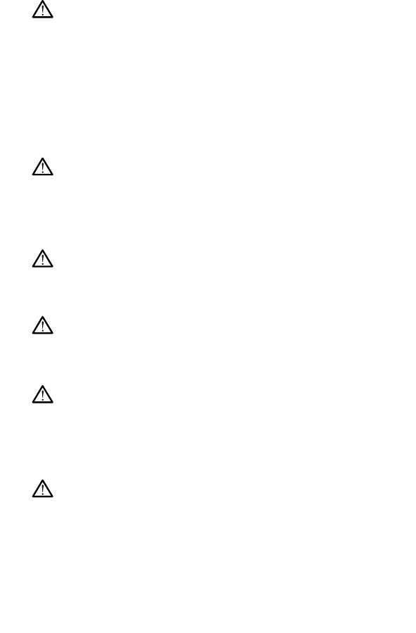
[1] Model 3300 Programmer [2] Stand Clip [3] Model 6755 Stand [4] storage pocket
Figure 1. Optional Stand for the LATITUDE Programming System
CAUTION: The power adapter normally gets warm when it is in use or
charging. Do not place the power adapter in the storage pocket of the stand
while it is in use or charging as the confined space will not allow the heat to
dissipate adequately.
External Printer
The LATITUDE Programming System supports a broad range of external USB
2.0 and USB 3.0 printers. Refer to "Connections" on page 16 to connect the
printer’s USB cable.
Some Bluetooth®printers are also supported. Refer to the Network and
Connectivity Operator’s Manual (Model 3924) for additional setup and use
information.
USB Grounding Plug and Cable
A USB grounding plug and cable may be used with the Model 3300
Programmer to provide an earth ground to decrease noise interference to the
LATITUDE Programming System. Contact your hospital/clinic biomedical
engineering department for this standard piece of equipment.
WARNING:
The use of any cables or accessories with the LATITUDE Programming
System other than those provided by or specified by Boston Scientific could
result in increased electromagnetic emissions, decreased electromagnetic
immunity, or electrical shock of the LATITUDE Programming System. Anyone
connecting such cables or accessories to the LATITUDE Programming
System, including the use of MSOs (Multiple Socket Outlets), may be
configuring a medical system and is responsible to ensure that the system
complies with the requirements of IEC/EN 60601-1, Clause 16 for medical
electrical systems.

16
External Display
You can use an external monitor (or equivalent) that can synchronize to any
horizontal scan frequency.
NOTE: External monitors may require an adapter and/or cable to connect to
the DisplayPort on the Programmer.
NOTE: Equipment connected to the external connections must comply with
applicable standards for data processing equipment and for medical
equipment.
WARNING:
The use of any cables or accessories with the LATITUDE Programming
System other than those provided by or specified by Boston Scientific could
result in increased electromagnetic emissions, decreased electromagnetic
immunity, or electrical shock of the LATITUDE Programming System. Anyone
connecting such cables or accessories to the LATITUDE Programming
System, including the use of MSOs (Multiple Socket Outlets), may be
configuring a medical system and is responsible to ensure that the system
complies with the requirements of IEC/EN 60601-1, Clause 16 for medical
electrical systems.
CONNECTIONS
Refer to Figure 2 Right Side Panel of the Programmer on page 17 and Figure 3
Left Side Panel of the Programmer on page 17 to identify the port connections
to the Programmer.
17
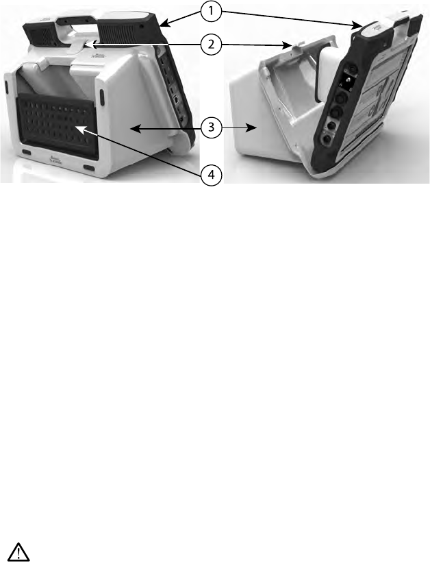
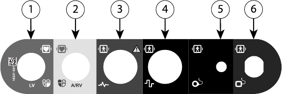
Patient Side Panel (Right Side)
[1] Model 6763 PSA Cable for LV (green) [2] Model 6763 PSA Cable for A/RV (light gray) [3] Model
3153 ECG Cable (dark gray) [4] connection port for future use (brown) [5] Model 3203 S-ICD
Telemetry Wand (black) [6] Model 6395 Telemetry Wand (blue)
Figure 2. Right Side Panel of the Programmer
Physician Side Panel (Left Side)
NOTE: Equipment connected to the external connections must comply with
applicable standards for data processing equipment and for medical
equipment.
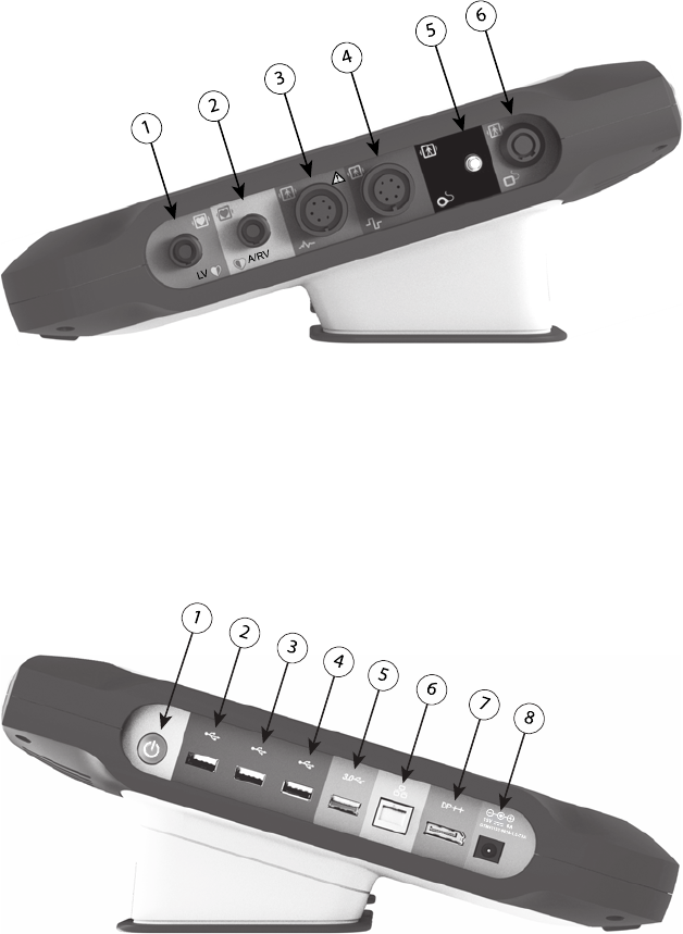
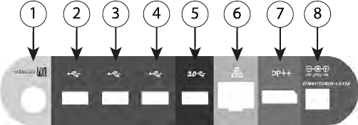
[1] Power (on/off) button (light gray) [2-4] USB 2.0 ports (dark gray) [5] USB 3.0 port (blue) [6]
Ethernet port (orange) [7] DisplayPort Out (red-orange) [8] DC power connection for Model 6689
power adapter (green)
Figure 3. Left Side Panel of the Programmer
18
Indicator Lights
The Programmer has an indicator light on the left side of the device contained
within the power (on/off) button . The Model 6395 Telemetry Wand has an
indicator light on the front face. The functions are described below.
•Power (on/off) button is lit when the Programmer is on.
• The light on the Model 6395 Telemetry Wand illuminates to indicate that
inductive telemetry is established and is actively communicating to a PG.
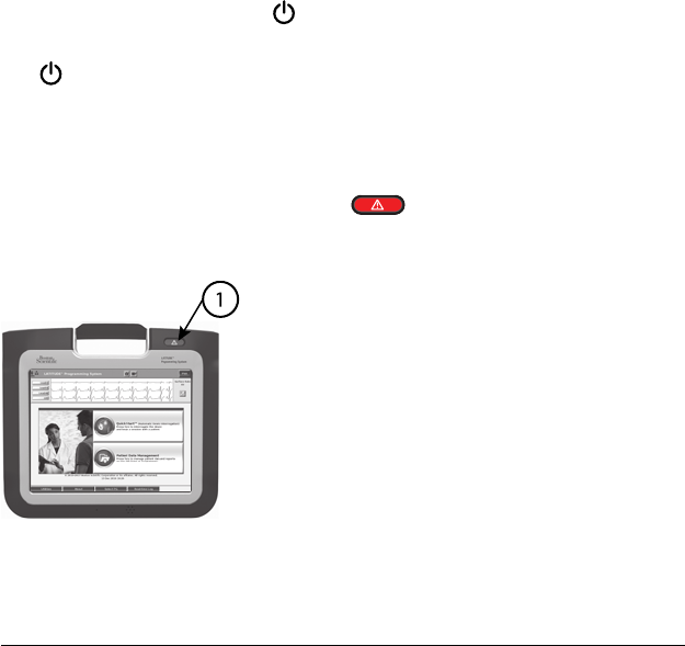
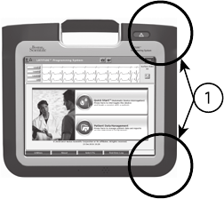
STAT Button
The Programmer has a red STAT button on the front top-right of the
device. Depending on the situation, the STAT function provides STAT PACE,
STAT SHOCK, or DIVERT THERAPY.
[1] Red STAT button
Figure 4. Front View of LATITUDE Programming System Indicating the Red STAT
Button Location
USING THE LATITUDE PROGRAMMING SYSTEM
Preparation for Use
Battery Charge Level and Charging
The Lithium-ion battery for the Programmer is not charged when shipped. To
charge the battery, perform the following steps.
NOTE: Before using the battery with the LATITUDE Programming System,
ensure that the battery is fully charged.
1. Connect the AC power and turn on the Programmer. See Figure 3 Left
Side Panel of the Programmer on page 17.
2. Check the battery charge by noting the battery status indicator in the upper
left of the screen, which displays the battery charge percent. See Figure 9
Main Screen on page 25.
3. Nominally, battery charging can take 1-2 hours when the battery is less
than 30% charged.
19
NOTE: As long as the Programmer is plugged in (connected to AC
power), the battery will charge. The Programmer does not have to be
powered on to recharge the battery.
Prepare a Telemetry Wand
Depending on the PG being used, prepare the appropriate wand.
Model 6395 Telemetry Wand
CAUTION: The Model 6395 Telemetry Wand is shipped non-sterile. Remove
the wand from all packaging material before sterilizing it. If the wand is to be
used in a sterile field, it must be actively sterilized before use or enclosed in a
disposable sterile surgical sheath (Model 3320) during use. Refer to "Cleaning
the Programmer and Accessories" on page 42 for sterilization and cleaning
information.
If needed, prepare the Model 6395 Telemetry Wand for the sterile field by
following the procedures in "Cleaning the Programmer and Accessories" on
page 42 or by enclosing the wand in a Model 3320 Sterile Sleeve.
Model 3203 S-ICD Telemetry Wand
CAUTION: The Model 3203 S-ICD Telemetry Wand is shipped non-sterile.
Remove the wand from all packaging material before use. If the wand is to be
used in a sterile field, it must be enclosed in a sterile intraoperative probe cover
(Model 3320) during use. Refer to "Cleaning the Programmer and Accessories"
on page 42 for cleaning information.
To use the Model 3203 S-ICD Telemetry Wand as an additional antenna for RF
telemetry, refer to "Prepare for ZIP (RF) Telemetry" on page 22.
If needed, prepare the Model 3203 S-ICD Telemetry Wand for the sterile field
by enclosing the wand in a Model 3320 Sterile Sleeve.
Cable Connections
For connector locations, refer to the panels on the Model 3300 Programmer
System right side and left side (Figure 2 Right Side Panel of the Programmer
on page 17 and Figure 3 Left Side Panel of the Programmer on page 17).
Make Patient Side Connections
As needed, make the following connections on the right side of the
Programmer.
20
[1] Model 6763 PSA Cable for LV (green) [2] Model 6763 PSA Cable for A/RV (light gray) [3] Model
3153 ECG Cable (dark gray) [4] connection port for future use (brown) [5] Model 3203 S-ICD
Telemetry Wand (black) [6] Model 6395 Telemetry Wand (blue)
Figure 5. Right Side (Patient) Panel
1. For PSA measurements, connect the appropriate PSA cable to the
appropriate connector (LV or A/RV).
2. Connect the appropriate telemetry wand to its connector:
• Model 6395 Telemetry Wand
• Model 3203 S-ICD Telemetry Wand
NOTE: Under battery-operated power with wanded telemetry, the
LATITUDE Programming System is able to communicate with the PG
beneath the patient’s skin. For most pectoral implants, the telemetry is
sufficient to communicate with the PG. For abdominal implants, the
distance may be greater and battery-operated power only may not be
sufficient to maintain reliable communication. To achieve maximum
inductive telemetry communication with the PG, always use external
power.
3. Connect the surface ECG patient cable to the ECG connector. Attach the
surface electrodes to the patient in a standard three-wire or five-wire
configuration.
NOTE: The ECG function may be sensitive to high-frequency ambient
noise when the ECG inputs are not attached. If the electrodes are not
attached to the patient, they may be sensitive to high-frequency
environmental noise and therefore provide a poor signal. The ECG surface
traces can be turned off if excessive noise is present.
NOTE: The ECG function is intended to be used during patient exams for
tests such as pace threshold testing.
NOTE: The ECG function may exhibit noise interference if the
LATITUDE Programming System is in close proximity to high-frequency
electrosurgical equipment. For corrective action, refer to "Troubleshooting"
on page 52.
4. If MICS or RF telemetry is insufficient, connect the Model 3203 S-ICD
Telemetry Wand to its connector. The S-ICD telemetry wand acts as an
extra RF antenna. Orient this wand as necessary to improve RF telemetry
21
performance. Refer to "Steps to Improve ZIP (RF) Telemetry Performance"
on page 23 for additional information.
Make Physician Side Connections
As needed, make the following connections on the left side of the LATITUDE
Programming System.
[1] Power (on/off) button (light gray) [2-4] USB 2.0 ports (dark gray) [5] USB 3.0 port (blue) [6]
Ethernet port (orange) [7] DisplayPort out (red-orange) [8] DC power connection for Model 6689
Power Adapter (green)
Figure 6. Left Side (Physician) Panel
1. Connect the power cord to the DC receptacle on the left side panel of the
Programmer.
2. To connect an external USB printer, attach the appropriate USB cable (2.0
or 3.0) to the appropriate USB port on the Programmer. Then, ensure that
the printer is connected to external power.
NOTE: Connect the printer to the USB port, then wait 30 seconds for the
system to recognize the printer before sending files to the printer.
NOTE: The LATITUDE Programming System has Bluetooth®capability,
which can be used to connect with Bluetooth®capable printers.
3. Use the DisplayPort Out connector to attach an external monitor. Then,
ensure that the monitor is connected to external power.
4. To connect to a LAN, attach an Ethernet cable to the Ethernet port.
NOTE: Connect the Ethernet cable only to the RJ45 Ethernet port
connector on the Model 3300 Programmer.
NOTE: Additional steps need to be completed when using Bluetooth®or
LAN communications. Refer to the Network and Connectivity Operator’s
Manual (Model 3924) for additional information.
5. Ensure the power adapter cable is plugged into the DC port on the left side
of the Programmer and the power cord is plugged into the power adapter.
NOTE: Ensure the left side of the device is accessible at all times so that
the power cord can be connected and disconnected.
22
Electrosurgical Cables
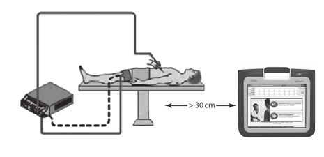
Electrosurgical cables must be kept at least 30 cm (12 in) away from the
LATITUDE Programming System to avoid false screen traces when
electrosurgical energy is applied.
Figure 7. Electrosurgical Cables Distance from LATITUDE Programming System
Prepare for ZIP (RF) Telemetry
NOTE: The ZIP telemetry feature is not available for all Boston Scientific PGs.
For more information, refer to the associated product literature for the PG being
interrogated.
For PGs that communicate using ZIP telemetry:
1. For optimum ZIP telemetry communication, position the LATITUDE
Programming System within 3 m (10 ft) of the PG.
2. Remove obstructions between the LATITUDE Programming System and
the PG.
NOTE: Reorienting or repositioning the LATITUDE Programming System
may improve ZIP telemetry performance.
NOTE: The Model 3203 S-ICD Telemetry Wand may be used as a third RF
antenna to improve RF telemetry performance.
NOTE: If ZIP telemetry performance is not successful, use the Model 6395
Telemetry Wand to interrogate the PG.
23
[1] Internal antenna locations, approximate
Figure 8. Front View of LATITUDE Programming System Indicating Approximate
Antenna Locations Within the Enclosure
Steps to Improve ZIP (RF) Telemetry Performance
Perform the following to increase RF telemetry performance:
1. Disconnect all unused cables and wands and stow them.
2. All remaining connected patient side cables (PSA, ECG) should exit
perpendicular to the Programmer and (as much as possible) directly
toward the patient.
3. All remaining connected physician side cables (power, USB, DisplayPort,
Ethernet) should be routed away from the patient.
4. If there are any electrical equipment (laptop, monitor, etc.) or metal objects
adjacent to the Programmer, move them away from the Programmer as
much as possible.
5. Move the Programmer closer to the patient, ideally away from a busy or
crowded location in the room.
6. Change the Programmer orientation by rotating the Programmer up to 45
degrees clockwise or counter-clockwise or by placing the Programmer into
the optional Model 6755 Stand.
7. Ensure that clinic staff are not in the line of sight between the Programmer
and the implanted PG.
8. If telemetry is still not consistent, attach the Model 3203 S-ICD Telemetry
Wand and place it within 0.6 m (2 ft) of the implanted PG. In the sterile
field, use a Model 3320 Intraoperative Probe Cover and place the wand on
top of the patient’s stomach.
• When not used for RF telemetry, be sure to disconnect the Model
3203 S-ICD Telemetry Wand from the Programmer to prevent
telemetry dropouts.
9. If ZIP telemetry is not successful for a PG capable of RF telemetry, use the
Model 6395 Telemetry Wand to interrogate the PG.

24
Startup
To turn on the LATITUDE Programming System:
1. Connect the power adapter cord to the DC receptacle on the left side panel
of the LATITUDE Programming System (Figure 3 Left Side Panel of the
Programmer on page 17).
2. Plug the AC power cord into the power adapter and an appropriate AC
outlet.
3. Press the power button .
NOTE: It can take up to one minute for the Model 3300 Programmer to
complete its self tests and display the startup screen. During this time, the
screen may be flashing or blank.
4. Wait for the startup screen to appear.
NOTE: During system startup, observe the screen for any messages. If
an error message appears, do not use the device, write a detailed
description of the error, and contact Boston Scientific using the information
on the back cover of this manual.
5. When startup is complete, the main screen displays (Figure 9 Main Screen
on page 25), and the system is ready for use.
The Programmer’s touchscreen allows you to select items such as buttons,
check-boxes, and tabs that are displayed on the screen. Only one item can be
selected at a time.
NOTE: The screen images in this manual are representative and may not
exactly match your screens.
CAUTION: If you want to use a stylus, ensure that it is a projected
capacitance stylus. The use of any other object could damage the touchscreen.
25
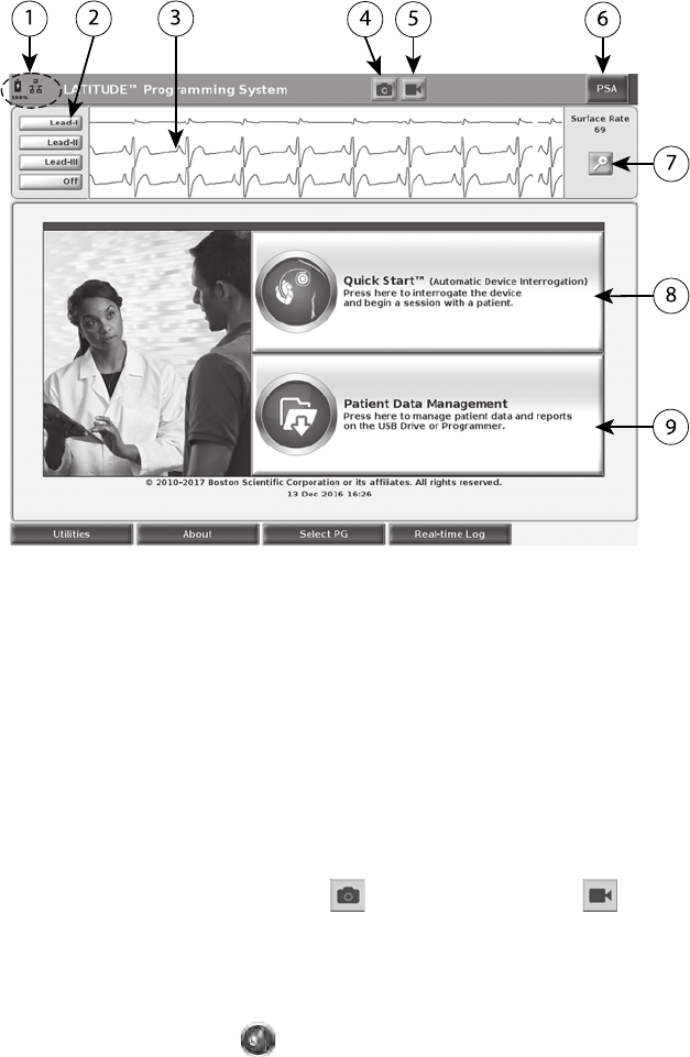
[1] Battery status, Ethernet, and Bluetooth®indicators [2] ECG and EGM lead trace selections, up to
four [3] lead trace display area [4] Snapshot button [5] Real-time Recorder button [6] PSA application
button [7] Magnify Traces button [8] Quick Start button [9] Patient Data Management button
Figure 9. Main Screen
When the LATITUDE Programming System is powered on, a Start Application
window displays a progress bar as the software loads. Normally this takes up to
one minute. When complete, the main screen displays the following as
illustrated in Figure 9 Main Screen on page 25:
• The status area displays battery charge status and Wi-Fi, Ethernet, and
Bluetooth®connectivity indicators
• The lead trace display, which can show up to four lead traces for patient
assessment such as from a surface ECG or a PSA
• There are two buttons (Snapshot and Real-time Recorder ) at the
top of the screen for capturing real-time recordings of lead traces during
ECG, PG, and PSA activity
• The PSA button activates the PSA application (see "Pacing System
Analyzer (PSA)" on page 31)
• The Quick Start button initiates PG communication to read a specific
PG application
26
• The Patient Data Management button accesses patient data for
export, printing, transfer, and deletion
• The Magnify Traces button enlarges the lead trace area to fill the
display window and provides additional information as illustrated in Figure
10 Magnify Traces Screen (During PG Session) on page 26
Figure 10. Magnify Traces Screen (During PG Session)
At the bottom of the screen are the following:
• The Utilities button, which allows access to LATITUDE Programming
System information and setup functions the user may use prior to
accessing the application software
• The About button, which allows the user to view, print, or save to a USB
pen drive the LATITUDE Programming System configuration information
(applications installed on the system and their associated version
numbers)
• The Select PG button, which allows the desired PG application software to
be selected and started, and includes the DEMO MODE option for PG
applications (see "Demo Mode" on page 33)
• The Real-time Log button, which provides access to recording of various
events from surface ECG and PSA
• The date and time are located at the bottom-center area of the screen as
shown in Figure 9 Main Screen on page 25 (see "Date and Time Tab" on
page 34 for timezone setting)

27
PSA Button
The PSA button in the upper right of the startup screen switches the screen
view and activates the PSA application. Refer to the Pacing System Analyzer
(PSA) Operator’s Manual (Model 3222) for details and instruction on using this
application.
Quick Start Button
The Quick Start button on the main screen is used to automatically identify and
interrogate the implanted PG. Refer to "Start a Transvenous PG Session" on
page 29 for additional information.
Patient Data Management Button
The Patient Data Management application allows you to export, transfer, print,
read, and delete patient data, which has been saved to the Programmer hard
drive or USB pen drive. Refer to the Patient Data Management Operator’s
Manual (Model 3931) for details and instruction on using this application.
STAT Button for Transvenous PGs
The STAT button is at the top-right of the Model 3300 Programmer.
The following actions occur when the STAT button is pressed:
• When the PG is in storage, off, or monitor only mode, STAT SHOCK or
STAT PACE is delivered. If the STAT SHOCK or STAT PACE is delivered in
storage, the tachy mode changes to off.
• When in telemetry communication with a high-voltage (ICD or CRT-D) PG,
a pop-up displays allowing the user to initiate a STAT PACE, STAT
SHOCK, or DIVERT THERAPY command. If a PSA session is in progress,
a PSA STAT PACE option also displays.
• When in telemetry communication with a low-voltage PG, a pop-up
displays allowing the user to initiate a STAT PACE or DIVERT THERAPY
command. If a PSA session is in progress, a PSA STAT PACE option also
displays as shown in Figure 11 STAT Button Pop-up in a High-voltage PG
Session with the PSA Application Running on page 28.
• When not in communication with a PG, an Interrogate button displays with
text prompting the user to perform Quick Start to attempt to identify the
device (see Figure 12 PSA STAT PACE Button Pop-up Outside Any PG
session with the PSA Application Running on page 28). Once in a session
with an implanted transvenous device, press the red STAT button again to
display available options.
• STAT PACE - initiates PG STAT PACE functionality for any supported
transvenous device (ICD, CRT-D, Pacemaker/CRT-P).
• STAT SHOCK - initiates PG STAT SHOCK functionality for supported high-
voltage transvenous ICD and CRT-D PGs.
• DIVERT THERAPY - initiates PG DIVERT THERAPY for any supported
transvenous device (ICD, CRT-D, Pacemaker/CRT-P) and, while in a PG
session, stops the pending therapy.
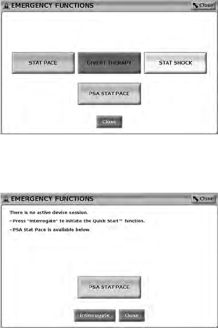
28
• PSA STAT PACE - when a PSA session has been enabled, it configures
the PSA with STAT PACE settings and functionality.
NOTE: All emergency function commands prompt the user to exit and start a
new session.
Figure 11. STAT Button Pop-up in a High-voltage PG Session with the PSA
Application Running
The top row buttons (STAT PACE, DIVERT THERAPY, and STAT SHOCK)
display during a PG session.
Figure 12. PSA STAT PACE Button Pop-up Outside Any PG session with the PSA
Application Running
If not in a PG session, the STAT button brings up the following dialog with no
buttons: "There is no active device session. Press “Interrogate” to initiate the
Quick Start™function."
If in a PSA session only (no PG interrogated), then the same dialogue displays
along with the PSA STAT PACE button (see Figure 12 PSA STAT PACE Button
Pop-up Outside Any PG session with the PSA Application Running on page
28).
29
Start a Transvenous PG Session
A transvenous PG session can be started two ways:
1. Use the Quick Start button to automatically identify the PG that is
connected to the system.
2. Use the Select PG button to manually choose which application to start a
session with the PG device.
Quick Start (Button)
1. Place the Model 6395 Telemetry Wand over the PG, and select the Quick
Start button.
2. A message window displays, indicating one of the following conditions,
based on the implanted PG:
• Application startup in progress – If the software for the implanted PG
is installed on the LATITUDE Programming System, it will identify the
PG, start the correct application, and automatically interrogate the PG.
• PG not identified – If a non-Boston Scientific PG or a Boston Scientific
PG for which there is no application loaded on this Programmer is
interrogated, a message window displays indicating that the PG is not
identified.
• Out-of-range and noise messages display to notify the user that the
wand is out of range or telemetry noise is present.
3. To proceed with the interrogation session, refer to the associated product
literature for the PG being interrogated.
Select PG (Button)
Use the Select PG button at the bottom of the screen to manually interrogate a
transvenous PG.
NOTE: The Select PG button also allows you to access DEMO MODE. See
"Demo Mode" on page 33.
1. Place the Model 6395 Telemetry Wand over the PG, and click the Select
PG button on the startup screen.
2. Select the icon that represents the desired PG family.
3. Click the Interrogate button on the pop-up window.
4. To proceed with the interrogation session, refer to the associated product
literature for the PG being interrogated.
For more information about the Quick Start and Select PG options, refer to the
associated product literature for the PG being interrogated.
Surface ECG
To run a surface ECG:
1. Connect the ECG cable to the Model 3300 Programmer.
2. Connect the cable to the electrodes attached to the patient.

30
3. As needed, use the Snapshot and Real-time Recorder buttons to record
ECG trace information.
The ECG or PSA traces will display on the main screen. Refer to Figure 9 Main
Screen on page 25 for additional main screen information.
ECG Display
When the ECG patient cable is connected to the patient and the Programmer,
the ECG display shows surface ECG signals without PG interrogation.
If ECG information is desired to be reviewed or saved, use the Snapshot or
Real-time Recorder buttons to create a real-time log.
NOTE: The LATITUDE Programming System can display four surface traces
of up to six limb leads or one chest lead. The top displayed lead will be
annotated with the pacing spike marker if that feature is selected. To display
the pacing spike markers correctly, the electrodes connected to the Lead-II
display trace must be connected to the patient regardless of which lead is
displayed. The Surface Rate will display the ventricular rate.
NOTE: The ECG functionality of the LATITUDE Programming System is
intended to support diagnostic activities pertaining to implanting, programming,
and monitoring Boston Scientific implantable PGs. The LATITUDE
Programming System is not intended for use as an ECG monitor or general
diagnostic device.
WARNING:
Operation of the LATITUDE Programming System with physiological signals
that are lower than the minimum detectable amplitude may cause inaccurate
results.
ECG Full Screen Display
To expand the ECG display to a full screen, select the Magnify Traces button
on the right side of the trace display area, then use the following screen
buttons to change the values and appearance of the traces (see Figure 10
Magnify Traces Screen (During PG Session) on page 26):
• Trace Speed – Select the desired speed on the ECG display: 0 (stop), 25,
or 50 mm/s
• Trace 1, Trace 2, Trace 3, and Trace 4 – Select the lead traces to be
displayed
• Gain – Select the appropriate value to adjust the surface gain of the traces
that are captured on printouts
• Calibrate button – Transmits a 1 mV calibration pulse so the user has a
reference point to evaluate amplitudes
• Baseline button – Forces the trace back to the baseline and is normally
used after a defibrillation shock
• Enable Surface Filter – Select the check box to minimize noise on the
surface ECG
31
• Display Pacing Spikes – Select the check box to show detected pacing
spikes, annotated by a marker on the top waveform
• Show PG Markers – When in a PSA application session, select the check
box to enable the PG markers.
NOTE: The values as set up on the startup screen will be the defaults used
for the application traces. The corresponding values can be changed from the
trace selections screen while in the application. For detailed application
programming instructions, refer to the associated product literature for the PG
being interrogated.
Intracardiac Electrogram
Intracardiac electrograms may be displayed on the Programmer screen.
Intracardiac electrograms and event markers can be captured and printed
using the Real-time Log feature. For detailed instructions, refer to the
associated product literature for the PG being interrogated.
Pacing System Analyzer (PSA)
The PSA application is used to assess electrical performance and placement of
cardiac lead systems during implant of cardiac rhythm management devices.
The PSA application displays real-time EGM traces and event markers for each
enabled channel. Real-time EGMs display on the same screen as the surface
ECG, which includes a heart-rate indicator.
Refer to the Pacing System Analyzer (PSA) Operator’s Manual (Model 3222)
for additional information on how to use the PSA application of the LATITUDE
Programming System, Model 3300.
Patient Data Management Utility
The Patient Data Management application provides the ability to generate
reports, and print, save, or transfer related data. The printable reports detail PG
functions, stored patient data, and test results. Stored patient session data can
be recalled later in the patient session for analysis (for certain applications
only) and saved to the Model 3300 Programmer hard drive and/or saved to a
removable USB pen drive and optionally encrypted.
Refer to the Patient Data Management Operator’s Manual (Model 3931) for
additional information on the use of this application.
Parameter Changes, Data Entry, Demo Mode, and
Utilities
Changing Parameter Values
The screens for many of the features contain parameter information that can be
changed via either a palette window or a keyboard window.
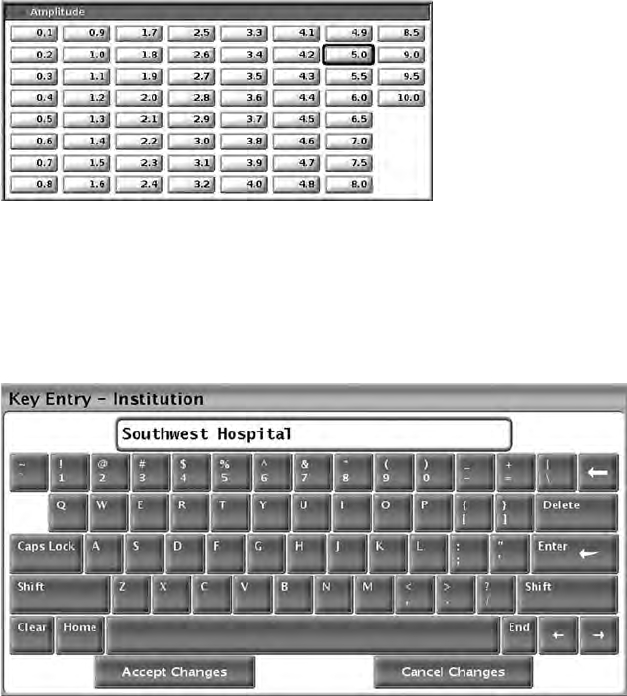
32
Figure 13. Palette Window - Parameter Selection Example
Palette Window
To change a parameter value, first select the appropriate parameter’s value
box. A palette window will appear. Select a value from the palette window by
touching the desired value; the window will automatically close when a
selection is made. To close a window without making a selection, touch the
screen outside the window.
Figure 14. Keyboard Window Example
Keyboard Window
Some screens display value boxes that require unique data to be entered,
typically from a keyboard window. To enter data from a keyboard window, first
select the appropriate value box. A keyboard window will appear. Touch the
first character of the new value; it will appear in the data-entry box in the
graphic keyboard. Continue until the entire new value appears in the box. To
delete one character at a time, starting with the last character, select the left
arrow key on the graphic keyboard. Each time the left arrow key is selected, a
character will be deleted in the box. To cancel any deletions or additions just
made, select the Cancel Changes button on the graphic keyboard. When all
the appropriate characters have been selected, select the Accept Changes
button on the graphic keyboard.
33
NOTE: If, when the keyboard window initially appears, it contains data in the
data-entry box, select the Clear button on the graphic keyboard to delete all the
characters in the data-entry box.
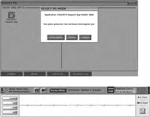
Demo Mode
To access the demonstration (DEMO) mode, click on the Select PG button at
the bottom of the screen, identify the device/family by clicking the appropriate
icon, then click the Demo button on the SELECT PG MODE pop-up.
Figure 15. SELECT PG MODE (Demo) Pop-up (ICD/CRT-D Selected)
Figure 16. PG Demo Mode
The main application screen displays with the demo mode message and
DEMO MODE logo at the top of the screen as illustrated in Figure 16 PG Demo
Mode on page 33. The software application screens displayed during the demo
mode reflect the features and programmable values of the PG family selected.
To exit the demo mode, select the End Session button in the lower right corner
of the screen.
Utilities Button
Before accessing the PG software application, you can select the Utilities
button to perform the following actions described in this section.
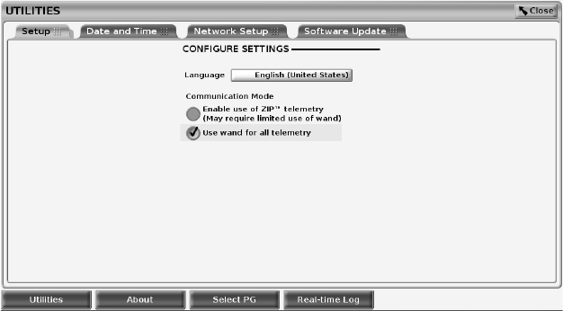
34
Figure 17. Utilities
The Utilities screen displays four tabs – Setup, Date and Time, Network Setup,
and Software Update.
Setup - Configure Settings
The Setup tab (see Figure 17 Utilities on page 34) allows you to:
• Change the language displayed.
• Enable wanded telemetry or ZIP telemetry (if it is approved for use in your
geography).
• As indicated in Figure 17 Utilities on page 34, ZIP telemetry may not be
enabled (the button is grayed out). If needed, contact Boston Scientific
using the information on the back cover of this manual to have a
representative enable ZIP telemetry.
Date and Time Tab
The Date and Time tab is used to select the TIME ZONE for the Programmer.
The date and time display at the bottom of the main screen.
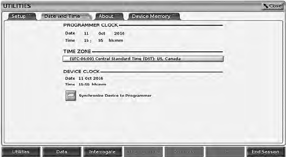
35
Figure 18. Utilities – Date and Time
NOTE: The LATITUDE Programming System clock synchronizes
automatically when connected to a network. If there is no network connection,
then the Boston Scientific representative can set the Programmer internal clock
using a special USB key.
NOTE: If a pop-up displays asking to synchronize the clocks, follow the
prompts to synchronize them.
Network Setup Tab
The Network Setup tab provides connectivity to networks and devices via
Wi-Fi, Bluetooth®, and Ethernet. Refer to the Network and Connectivity
Operator’s Manual (Model 3924) for additional network configuration and setup
information.
Software Update Tab
The Software Update tab allows you to install software updates. The user may
choose from downloading and installing all updates or reviewing and selecting
updates from those available.
Updates are delivered online via the Internet. In addition, updates may be
supplied on USB pen drives. Contact your local Boston Scientific
representative using the information on the back cover of this manual for
additional details concerning software updates on a USB pen drive.
Online Updates
From the Utilities screen, select the Software Update tab, which displays two
buttons:
• Easy Install–directly begins downloading all available and qualified update
packages. Once complete, the Programmer automatically restarts in install
mode, completes the update, and returns to normal operation.
• Custom Install–displays the available and qualified update packages for
user review/selection. Once the user completes the selection(s), they can
proceed with the update and installation process.

36
Figure 19. Utilities - Software Update
NOTE: Mandatory updates must be installed and cannot be unselected.
Boston Scientific is automatically informed when the software update has been
successfully downloaded.
If the download is not successful, retry the download before contacting Boston
Scientific for assistance.
Once downloading completes successfully, the Programmer restarts in install
mode and displays the list of qualified Update Packages. Click on the Install
button to begin installation.
When installation is complete, the programmer will restart (reboot).
NOTE: Allow the Programmer to fully restart because an update confirmation
will be sent via the network to Boston Scientific indicating a successful software
install.
Offline Updates
The Programmer can be updated via a special Software Install8USB pen drive.
When the software installation completes an offline update, power the
Programmer off and back on to complete the process.
NOTE: Allow the Programmer to fully restart because an update confirmation
will be sent via the network to Boston Scientific indicating a successful software
install.
About Button
Select the About button to display the About screen.
8. Software Install via USB pen drive is available only by your Boston Scientific representative.
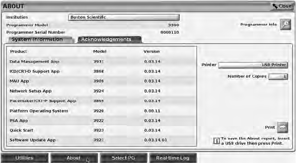
37
Figure 20. About Screen
Use the About screen to perform the following actions:
• Change the name of the institution. Select the value box next to Institution.
Refer to detailed instructions for entering new data using the keyboard
window (Figure 14 Keyboard Window Example on page 32).
• View the LATITUDE Programming System model and serial number
information.
• Select the System Information tab and view the LATITUDE Programming
System information including the version numbers of the system software
and the installed software applications.
• Print the LATITUDE Programming System information (known as the
About report).
– From the About screen (see Figure 20 About Screen on page 37)
select a printer (USB or Bluetooth®), number of copies, and then
select the Print button.
NOTE: If a USB pen drive is inserted in the Model 3300 Programmer
when the About report is created, the report is converted to a PDF and
saved to the USB pen drive.
Selecting a PG
To select a PG, first select the Select PG button, shown at the bottom of Figure
20 About Screen on page 37, to display the SELECT PG screen.
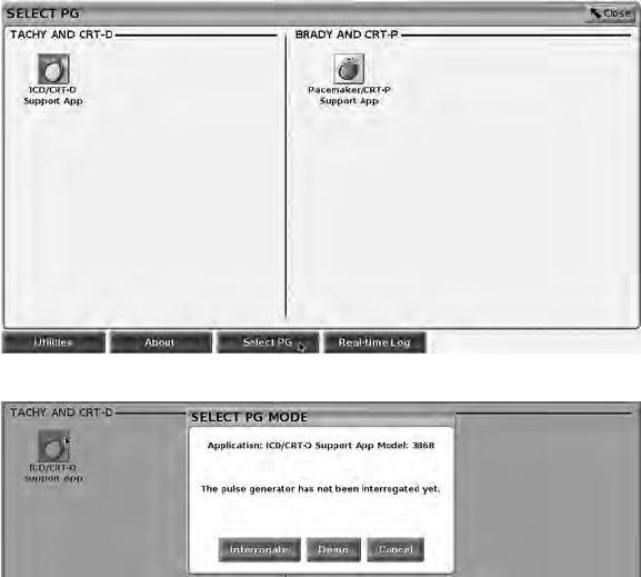
38
Figure 21. SELECT PG Screen
Figure 22. SELECT PG MODE
Select the device icon button (Figure 21 SELECT PG Screen on page 38), then
select the Interrogate button in the message pop-up as illustrated in Figure 22
SELECT PG MODE on page 38.
Once Interrogated, the application loads, checks system status, and then
displays the Summary screen (Figure 23 Summary Screen on page 39) for the
chosen device therapy.
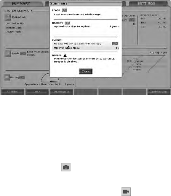
39
Figure 23. Summary Screen
If the PG device is not found, a device not supported message displays and
allows you to end the session.
Real-time Log for Transvenous PGs
The LATITUDE Programming System provides recording of various real-time
ECG and EGM events from a transvenous PG and PSA.
Two buttons on the header bar of the screen are used for real-time recording of
lead traces and PSA activity.
• The Snapshot button – records up to 12 seconds per button press (10
seconds after and 2 seconds before). Press once to start and again to
stop.
• Real-time Log – the Real-time Recorder button records continuously
upon button press, and stores data in 3-minute segments until a second
press ceases recording. While recording is in progress, the icon blinks to
reflect that storage is ongoing.
• Up to 100 individual recordings can be maintained during a session. In the
event more than 100 are captured, the oldest will be deleted to
accommodate newer. A Real-time Log is not retained from session to
session; if not saved as a PDF or printed, it is deleted upon ending the
current device session or starting a new device session.
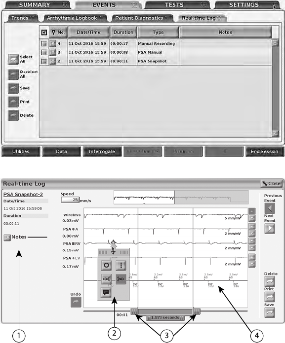
40
Figure 24. Real-time Log – List Screen
[1] Notes area [2] Real-time Log Tools pop-up [3] Electronic Calipers (slide bar) to adjust time span of
event [4] Real-time Log Event display
Figure 25. Real-time Log – Event Trace Example
The Notes button in the Notes area can be used to add comments. A Real-time
Log can be customized using the tools in the Real-time Log Tools pop-up. The
Electronic Calipers at the bottom of the screen can be adjusted to measure the
desired time span.
Real-time Log Tools
Select any part of the Real-time Log Event display, and the Tools pop-up
displays as in Figure 25 Real-time Log – Event Trace Example on page 40. At
the top center of the pop-up is an arrow and a target icon. When a tool is
selected, the tool action occurs at that target point on the screen. A new Tools

41
pop-up displays each time you select another part of the Real-time Log Event
display, so that you can use multiple tools anywhere on the display.
The five tools are:
• Circle tool –places a circle on the display at the target point.
• Line tool –places a dashed vertical line on the display at the target
point.
• Left scissor tool –removes the left-hand portion of the display from the
target point.
• Right scissor tool –removes the right-hand portion of the display from
the target point.
NOTE: When using the scissors tools, the original trace is still available
in the Real-time Log along with the actual scissored portion.
• Annotation tool - displays a keyboard to type in any notes, which then
appear on the trace.
Electronic Calipers
Use the Electronic Calipers (slide bar) to adjust the time span of the Snapshot
trace. The time interval between the calipers is measured in seconds. A caliper
can be repositioned by selecting it and then dragging it to expand or collapse
the time frame. For detailed instructions on using the Electronic Calipers, refer
to the associated product literature for the PG being interrogated.
Real-time Log Events
PG events that qualify for automatic real-time recording are listed in Table 1 PG
Events on page 41.The device action that initiates storage is recorded in the
Real-time Log.
Table 1. PG Events
Event Type Trigger Event Duration of Recording
(seconds)
Presenting Initial Interrogation
Completed
12
Electrocautery Mode Electrocautery Mode
Entered
12
STAT PACE STAT PACE Commanded 12
DIVERT THERAPY DIVERT THERAPY
Commanded
12
PACE THRESHOLD
TEST (AUTO, A, V, RV,
LV, Ampl, and PW)
Threshold Test Ended 12
INTRINSIC AMPL TEST
(A, V, RV, and SSI)
Intrinsic Ampl Test
Completed
12

42
Table 1. PG Events (continued)
Event Type Trigger Event Duration of Recording
(seconds)
TEMP BRADY Temp Start Entered,
Temp End Entered
Temp Start to
Temp End
STAT SHOCK STAT SHOCK
Commanded
48
Commanded V ATP ATP Commanded 12
Commanded V Shock Shock Commanded 12
Fib Induction High Fib Induction Commanded 24
Fib Induction Low Fib Induction Commanded 24
Shock on T Command Shock on T Commanded 43
Ventricular PES PES Commanded 24
Atrial PES PES Commanded 24
PG Ventricular Burst
Pacing
PG Burst Completed 24
PG Atrial Burst Pacing PG Burst Completed 24
PG Ventricular 50 Hz
Burst Pacing
PG Burst Completed 24
PG Atrial 50 Hz Burst
Pacing
PG Burst Completed 24
PG Fault PG Fault Occurred 12
PSA events are automatically labeled and stored. These event types are listed
in Table 2 PSA Events on page 42.
Table 2. PSA Events
Event Type Trigger Event Duration of Recording
(seconds)
PSA PACE THRESHOLD
TEST (A, RV, and LV)
PSA Save Threshold
button pressed
12
PSA BURST PACING PSA Burst button released 24
MAINTENANCE
Cleaning the Programmer and Accessories
In addition to turning off the Model 3300 Programmer and disconnecting the
power cord, Boston Scientific recommends removing the battery in the
43
Programmer before cleaning. See "Battery Status, Installation, Replacement,
and Recycling" on page 45 for instructions on removing the battery.
Clean the enclosure and touchscreen of the Programmer with a soft cloth
lightly dampened with water, isopropyl alcohol, or mild detergent.
• DO NOT use a hand disinfectant solution on the Programmer or the
display screen.
• DO NOT allow cleaning solution or moisture to come in contact with any
port on the sides of the Programmer.
• DO NOT allow cleaning solution or moisture to come in contact with the
speaker or microphone openings on the bottom front of the Programmer.
Figure 26. Microphone and Speaker Openings
The cables and the wands used with the LATITUDE Programming System are
not sterile when packaged. Only the Model 6763 PSA cable and the Model
6395 Telemetry Wand can be sterilized. All other cables and the Model 3203 S-
ICD Telemetry Wand cannot be sterilized, but they can be cleaned.
WARNING:
Before cleaning and disinfecting the Programmer surfaces, power down the
device and disconnect the external power supply. Before operating the
LATITUDE Programming System, let cleaning and disinfection agents used on
the Programmer evaporate.
CAUTION: Do not use an abrasive cloth or volatile solvents to clean any
portion of the device. See "Cleaning the Programmer and Accessories" on
page 42 for recommended cleaning.
Cleaning Cables and Wands
When necessary, clean the cables and wands with a soft cloth dampened with
a mild cleaning solution such as green soap, green soap tincture (U.S.
Pharmacopoeia), Borax, or alcohol-free hand soap. Use a fresh soft cloth
dampened with sterile water to remove residue. Towel-dry or air-dry the cables.
• DO NOT use an ultrasonic cleaner.

44
• DO NOT immerse the cables.
• DO NOT immerse the Model 6395 Telemetry Wand or the Model 3203 S-
ICD Telemetry Wand.
• DO NOT allow fluid to enter the cavity of the Model 6395 Telemetry Wand
or the Model 3203 S-ICD Telemetry Wand.
NOTE: Discard the PSA and ECG cables and wands any time surface cracks
appear in the cables and/or the cables discolor, become visibly worn, or if
labeling becomes unreadable. See "Environmental Protection and Disposal" on
page 58 for disposal information.
Disinfecting ECG and PSA Cables
When necessary, disinfect the ECG or PSA cable using a 2% glutaraldehyde
solution (such as Cidex), a bleach solution (such as 10% Sodium
Hypochlorite), or a general disinfection solution approved for disinfection of
medical external devices in the appropriate concentration per the product
instructions for use.
Sterilization
NOTE: The Model 3203 S-ICD Telemetry Wand cannot be sterilized.
Ethylene Oxide (EO) Sterilization Instructions
The Model 6763 PSA cable and Model 6395 Telemetry Wand may be sterilized
using EO. Follow the recommendations of the EO sterilization equipment
manufacturer and allow the specified aeration time to fully elapse prior to use.
Parameter Value
Temperature maximum 60 ºC (140 ºF)
Pressure differential 106 kPa (15.4 psi)
Humidity maximum 85% non-condensing
EO dwell time maximum 2 hours
EO concentration minimum 450 mg/L
Minimum aeration time 12 hours at 60 ºC (140 ºF)
Number of sterilization cycles permitted 6763 PSA cable = 50
6395 Telemetry Wand = 25
Steam Sterilization Instructions
The Model 6763 PSA cable may be steam sterilized. Follow the
recommendations of the steam sterilization equipment manufacturer and allow
the specified steam dwell time to fully elapse prior to use.

45
Parameter Value
Temperature maximum 118 ºC (244 ºF)
Pressure differential 96.5 kPa (14 psi)
Steam dwell time maximum 30 minutes
Number of sterilization cycles permitted 50
Flash Sterilization Instructions
The Model 6763 PSA cable may be flash sterilized. Follow the
recommendations of the flash sterilization equipment manufacturer and allow
the specified dwell time to fully elapse prior to use.
Parameter Value
Temperature maximum 134 ºC (273 ºF)
Pressure differential 213.7 kPa (31 psi)
Flash dwell time maximum 6 minutes
Number of sterilization cycles permitted 50
Battery Status, Installation, Replacement, and
Recycling
The Programmer battery has been tested and approved for hospital and clinic
use. Battery status is a percent of charge remaining (see Figure 28 Battery
Status Icons Indicating Charge Percentage on page 46) and is displayed in the
upper left corner on all Programmer screens as illustrated in Figure 27 Battery
Status Indicator on Main Screen with AC Power On on page 46.
NOTE: The battery should be replaced when it no longer maintains a charge
above 25%.
NOTE: Depending on the age of the battery, a full charge should last for
approximately two hours of normal operation.
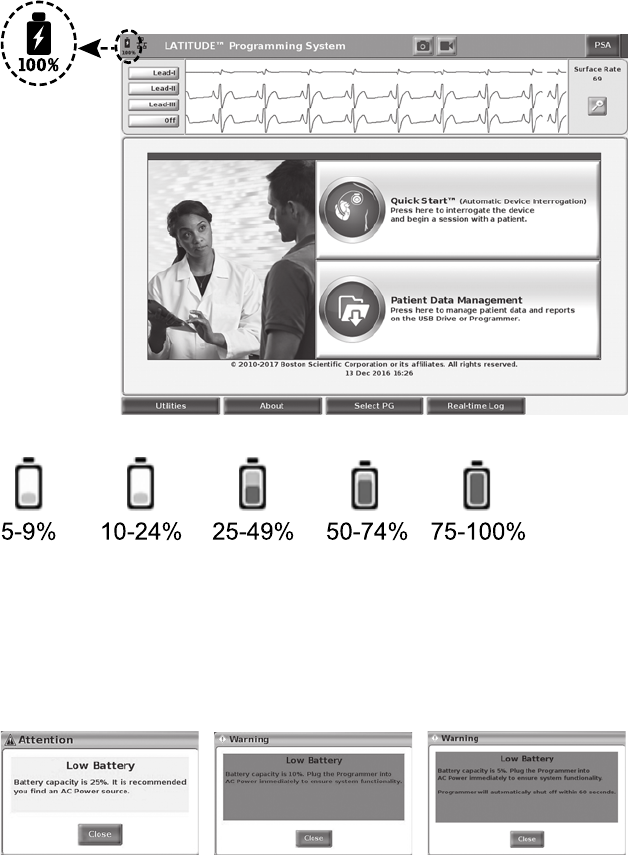
46
Figure 27. Battery Status Indicator on Main Screen with AC Power On
Battery color: <10% is red, 10-24% is yellow, 25-100% is green
Figure 28. Battery Status Icons Indicating Charge Percentage
An attention message displays on the Programmer screen when the battery
reaches 25% depletion. When the battery reaches 10% depletion or less, a
warning message displays. At 5%, there is another warning message followed
by a 60 second automatic shutdown.
Figure 29. Battery Status - Attention and Warning Pop-ups
In addition, there are battery status indicators on the top right of the battery
which indicate the remaining charge in 25% increments from 100%, 75%, 50%,
and 25%. See Figure 31 Replaceable Programmer Battery on page 47.
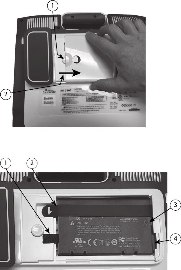
47
[1] Battery release button [2] Direction to slide cover for removal (reverse the direction to replace the
cover)
Figure 30. Battery Compartment on Underside of the Programmer
[1] Battery lift out tab [2] Battery retaining strap [3] Battery status indicator LEDs [4] Battery connector
terminals (partially hidden)
Figure 31. Replaceable Programmer Battery

48
Battery Replacement
NOTE: To obtain a replacement battery, contact Boston Scientific using the
information on the back cover of this manual.
To remove the battery:
1. Press and release the power button to turn OFF the Programmer.
2. If connected to AC power, unplug the AC power cord.
3. If connected to the optional stand, unclip the stand and remove it.
4. Place the device screen side down on a soft cloth.
5. Press and hold the battery cover button, then slide back the battery cover
as illustrated in Figure 30 Battery Compartment on Underside of the
Programmer on page 47.
6. Release the battery retaining strap as identified in Figure 31 Replaceable
Programmer Battery on page 47.
7. Lift out the battery using the black tab attached to the left side of the
battery.
WARNING:
When accessing the battery, ensure that power to the Programmer is
turned off. Do not touch the connector terminals in the battery
compartment while removing or replacing the battery because an
electrical charge is present.
To install the battery:
1. Insert the new battery (Model 6753) at a slight angle with the battery status
indicators on the top right, to make a secure connection between the
battery and Programmer contacts.
2. Press down on the left edge of the battery to ensure that the battery is fully
seated, to allow the battery cover to fit flush with the case.
3. Determine the charge status by pressing the battery status button on the
battery, which is located just above the battery status indicator LEDs
4. Replace the battery retaining strap.
5. Replace the battery cover by aligning the left edge of the cover with the
middle of the battery release button (see Figure 30 Battery Compartment
on Underside of the Programmer on page 47).
6. Close the battery cover by sliding the door to the left until you hear an
audible click.
7. If the battery charge status is less than 100%, connect the Programmer to
AC power. A full recharge from a depleted battery will take about 2 to 2 1/2
hours.
NOTE: As long as the Programmer is plugged in (connected to AC
power), the battery will charge. The Programmer does not have to be
powered on to recharge the battery. However, the Programmer must be

49
turned on in order to check the battery charge status (see Figure 9 Main
Screen on page 25).
NOTE: For best results, be sure to charge the battery to 100% before
using the Programmer on battery power only.
Battery Recycling
Boston Scientific recommends that the Lithium-ion battery should be
discharged to 25% or less of capacity, and should be recycled in a separate
collection for electrical and electronic equipment. Do not place the battery in
the trash.
NOTE: Do not include the battery when returning the Model 3300
Programmer to Boston Scientific Corporation.
WARNING:
The Model 6753 Battery is a Lithium-ion battery and, as such, is deemed a
Dangerous Good in regards to shipping. For air shipments, the battery charge
cannot exceed 30% per applicable aviation regulations. Shipping with a charge
greater than 30% is in direct violation of aviation regulations and may result in
significant fines to the shipper including the individual responsible for the
shipment. When shipping by air, a Lithium-ion battery handling label must be
applied to the outer shipping box visible to the carrier. There are no restrictions
for ground shipments nor is a Lithium-ion battery handling label required for
ground shipments.
If returning the Lithium-ion battery by air shipment, contact Boston Scientific
using the information on the back cover of this manual to obtain the proper
return shipment labeling and requirements.
Operation and Storage
The LATITUDE Programming System requires special handling. The internal
hard drive of the Model 3300 Programmer must be protected from abusive
handling. To protect the device from damage, refer to the following information:
• DO NOT turn off the LATITUDE Programming System while the internal
hard drive is accessing data.
• DO NOT subject the LATITUDE Programming System to shocks or
vibrations.
• DO NOT place a magnet on the Programmer.
• DO NOT pour or splash liquid into or onto the Programmer.
• DO NOT strike, scratch, nick, or otherwise mar the touchscreen surface.
Be sure to use only fingers or a capacitive stylus on the touchscreen.
• DO NOT disassemble the LATITUDE Programming System.
• When transporting the LATITUDE Programming System from an outside
environment to an inside environment, allow the LATITUDE Programming
System to acclimate to ambient temperature before use.
• Turn off the LATITUDE Programming System when not in use and prior to
transporting it.

50
• Unplug all external cables and cords prior to transporting the LATITUDE
Programming System.
• Keep the vents on the bottom of the Programmer free from obstruction.
Operating and transport conditions are listed in "LATITUDE Programming
System Nominal Specifications" on page 66.
If the LATITUDE Programming System has been stored outside of its normal
operating conditions, let it sit at ambient temperature until it comes up to
operating temperature range before use.
While the Programmer is in operation, the fan will automatically turn on and off
as needed to maintain optimum internal temperature. The LATITUDE
Programming System is capable of continuous operation and will not shut off
automatically if unused for an extended period of time.
CAUTION: The LATITUDE Programming System is not waterproof or
explosion-proof and cannot be sterilized. Do not use the Programmer in the
presence of flammable gas mixtures including anesthetics, oxygen, or nitrous
oxide.
CAUTION: The Model 6753 Lithium-ion battery contains highly flammable
chemicals and should be handled with caution. Abuse of this battery can result
in fire or explosion. Read the following prior to using this battery:
• Do not expose the battery to temperatures above 140°F (60°C).
• Do not puncture the battery as it can lead to a fire or explosion. If the
battery housing is punctured, or otherwise visibly damaged, do not attempt
to use it.
• Do not strike the battery or otherwise subject it to strong impacts.
• Do not submerge the battery in any fluids.
• Do not connect the + and – terminals with wire or any conductive objects.
• Do not disassemble, modify, or repair the battery.
• Only use the Model 3300 Programmer to charge the battery. Use of any
other battery charger can permanently damage the battery or even cause
a fire or explosion.
Storing the LATITUDE Programming System
1. Exit the current software application by pressing the End Session button.
2. Press and release the power button to turn off the LATITUDE
Programming System.
NOTE: Before moving the LATITUDE Programming System, always exit
the software application and press and release the power button to turn
off the LATITUDE Programming System, then unplug the power cord.
NOTE: If using battery power, press and release the power button to
turn off the device.
3. Unplug the power cord from the wall.
51
4. Unplug all equipment cables from the side panels of the LATITUDE
Programming System.
NOTE: See each accessory’s product literature for transport and storage
conditions. Ensure each accessory is maintained within the appropriate limits.
Long Term Storage of the LATITUDE Programming System
If the Programmer is to be stored for long periods (e.g. months), remove the
battery to prevent it from discharging to a point where recharging would be
required in order to use it again. See "Battery Status, Installation,
Replacement, and Recycling" on page 45 for instructions on removing the
battery.
Maintenance Check and Safety Measures
LATITUDE Programming System Maintenance Check
Prior to each use, you should perform a visual inspection and verify the
following:
• Mechanical and functional integrity of the LATITUDE Programming
System, cables, and accessories.
• Legibility and adherence of the LATITUDE Programming System labels.
• Perform "Startup" on page 24. The normal power-up process verifies that
the LATITUDE Programming System has passed its internal checks and is
ready for use.
NOTE: The LATITUDE Programming System does not contain any user-
serviceable parts and it does not have a calibration requirement. Maintenance
does not require any additional steps.
The LATITUDE Programming System contains only one user-accessible
component, the Model 6753 replaceable Lithium-ion battery.
NOTE: The Programmer must be returned without the battery for
replacement or repair of any internal components. See "Battery Recycling" on
page 49 for additional details.
Safety Measurements
National regulations may require that the user, manufacturer, or manufacturer
representative periodically perform and document safety tests of the device. If
such testing is required in your country, follow the testing interval and extent of
testing as regulated in your country. If you do not know the national regulations
in your country, please contact your local Boston Scientific representative.
It is not necessary that technical and safety inspections be performed by
Boston Scientific personnel. However, technical and safety inspections of the
Programmer and its accessories must be performed by persons, who, based
on their training, knowledge, and practical experience, are capable of
adequately performing such inspections and who do not require instructions
with regard to the technical and safety inspection.
If IEC/EN 62353 is a required standard in your country, but no specific testing
or interval is specified, it is recommended that you perform safety testing using

52
the direct method as specified in IEC/EN 62353 at an interval of every 24
months or as per local regulations. Refer to "Compromised Programmer" on
page 66.
Service
For questions regarding operation or repair of the LATITUDE Programming
System, contact Boston Scientific using the information on the back cover of
this manual. The LATITUDE Programming System must be serviced by Boston
Scientific personnel only.
If the LATITUDE Programming System malfunctions and requires repair, help
to ensure efficient service by following these guidelines:
1. Leave the configuration of the instrument exactly as it was at the time of
malfunction. Contact Boston Scientific using the information on the back
cover of this manual.
2. Write a detailed description of the malfunction(s).
3. Save printouts or other materials that illustrate the problem, if possible.
4. Be sure to save all PG data to a USB pen drive before returning a
LATITUDE Programming System to Boston Scientific, as all patient and
PG data will be erased from the LATITUDE Programming System when it
is returned for service.
5. If the LATITUDE Programming System must be returned to Boston
Scientific for service, remove the Lithium-ion battery from the Programmer,
pack the device in the shipping container in which it was received or in a
shipping container provided by Boston Scientific. Do not include the
Lithium-ion battery when returning the Programmer to Boston Scientific
Corporation.
6. For the shipping address, contact Boston Scientific using the information
on the back cover of this manual.
TROUBLESHOOTING
If the LATITUDE Programming System does not operate properly, check that
electrical cords and cables are securely connected and that cords and cables
are in good working order (i.e., free of visible defects). Possible causes and
corrective actions for problems listed below.
Table 3. Possible Causes and Corrective Actions for LATITUDE Programming
System Problems
Symptom Possible Cause Corrective Action
Telemetry: poor,
intermittent, or no
communication
Incorrect application
software or incorrect
LATITUDE Programming
System for PG
Install proper application
software for PG in use.
Use correct LATITUDE
Programming System for
the PG being interrogated.
Contact Boston Scientific
using the information on

53
Table 3. Possible Causes and Corrective Actions for LATITUDE Programming
System Problems (continued)
Symptom Possible Cause Corrective Action
the back cover of this
manual to confirm PG and
Model 3300 Programmer
compatibility.
Incorrect telemetry wand Use only the Model 6395
Telemetry Wand for
transvenous PGs.
Poor connection between
a telemetry wand and the
Programmer
Disconnect and reconnect
the Model 6395 Telemetry
Wand to the Programmer.
Programmer running on
battery power only
Connect the Programmer
to AC power to improve
telemetry performance.
Excessive radio emissions
from equipment
Reposition the LATITUDE
Programming System.
Also see Noise problems:
ECG.
Incomplete telemetry
communication with Model
6395 Telemetry Wand
Reposition the Model
6395 Telemetry Wand
over the PG; repeat
interrogation.
Flip the wand over.
Disconnect and reconnect
the wand. Turn off the
Programmer, and then
turn it On. Repeat
interrogation.
Use another Model 3300
Programmer or Model
6395 Telemetry Wand.
Repeat interrogation.
If this does not correct the
issue, contact Boston
Scientific using the
information on the back
cover of this manual.
Telemetry RF signal
obstructed
Assure that a clear line-of-
sight path exists between
the LATITUDE
Programming System and
PG. Repeat interrogation.

54
Table 3. Possible Causes and Corrective Actions for LATITUDE Programming
System Problems (continued)
Symptom Possible Cause Corrective Action
Telemetry RF signal
interference
Reposition LATITUDE
Programming System.
Repeat interrogation.
RF Telemetry fails Reposition the Model
6395 Telemetry Wand
over the transvenous PG
and repeat interrogation.
Use the Model 3203 S-
ICD Telemetry wand as an
additional antenna.
LATITUDE Programming
System software version
not current
Contact Boston Scientific
using the information on
the back cover of this
manual.
Noise problems: ECG Improper patient
connections
Recheck patient leads for
adequate skin contact and
correct limb lead
placement. Confirm Right
Leg Drive is connected.
Consult ECG textbooks for
additional ECG
techniques.
Excessive radio emissions
from equipment
Check surrounding area
for electrical equipment
that is powered on and not
needed. Move unneeded
equipment away from
patient and/or LATITUDE
Programming System, or
turn off unneeded
equipment.
Route ECG cable away
from potential noise
sources such as other
equipment and associated
cabling to include AC
cords.
Ground Programmer to
the conductive patient bed
(when applicable) using a
USB grounding cable.
Intertwine excess ECG
lead lengths when
possible. Consult ECG

55
Table 3. Possible Causes and Corrective Actions for LATITUDE Programming
System Problems (continued)
Symptom Possible Cause Corrective Action
textbooks for additional
ECG techniques.
Check for building outlet
ground resistance less
than 10 Ω, when
measured with low
impedance techniques,
between the outlets and
from the outlets to other
grounded points in the
room (e.g., room bonding
point, cold-water pipe,
exam table, etc.).
Telemetry: interference Harmful interference
caused by the LATITUDE
Programming System or
the system is negatively
impacted by other RF
devices
Reorient or relocate the
devices.
Increase the separation
distance between the
devices.
Connect the equipment to
an outlet on a different
circuit or use as battery
powered.
Contact Boston Scientific
using the information on
the back cover of this
manual.
Missing shock markers
during the delivery of a
shock
Noise during shock
delivery may prevent the
shock marker from being
received at the maximum
telemetry distance of 6 cm
(2.35 in)
Review surface ECG for
confirmation of delivered
shock, if available. Review
PG’s Arrhythmia Logbook
for confirmation of
delivered shock.
Displayed clock does not
consistently keep time
after setting
Low internal clock battery The internal clock battery
is not field replaceable.
Return the LATITUDE
Programming System to
Boston Scientific for
replacement of the internal
clock battery.
Unable to print to a USB-
attached printer
Not connected properly Check the USB cable
connections between the
printer and the
Programmer.

56
Table 3. Possible Causes and Corrective Actions for LATITUDE Programming
System Problems (continued)
Symptom Possible Cause Corrective Action
No power Check the printer’s power
connection.
Printer not recognized Re-connect the printer to
the USB port, then wait 30
seconds for the system to
recognize the printer
before sending files to the
printer.
Touchscreen does not
respond or goes blank
Selecting inactive buttons
on the touchscreen
Select active buttons.
Touchscreen not
functioning
Turn off the LATITUDE
Programming System, and
then turn it on.
If this does not correct the
issue, contact Boston
Scientific using the
information on the back
cover of this manual.
LATITUDE Programming
System not responding
LATITUDE Programming
System not functioning
Turn off the LATITUDE
Programming System, and
then turn it On.
If this does not correct the
issue, contact Boston
Scientific using the
information on the back
cover of this manual.
External monitor not
displaying properly
Cable/adapter connection
to DisplayPort
Remove and re-insert
cable/adapter into
DisplayPort to re-
synchronize the video
signal.
HANDLING
The emissions characteristics of this equipment make it suitable for use in
industrial areas and hospitals (CISPR 11 class A).
Using an External ECG Monitor with the Model 3300 Programmer
Use the following accessories to set up the configuration described in this
section:
• Model 3153 Fixed Patient Leads ECG cable
• Model 6629 ECG–BNC Slave Cable
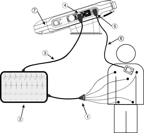
57
• Model 6395 Telemetry Wand
[1] Model 3153 ECG cable, [2] ECG monitor, [3] ECG-BNC slave cable, [4] Programmer ECG
connector, [5] Programmer Model 6395 Telemetry Wand connector, [6] Model 6395 Telemetry Wand,
[7] LATITUDE Programming System (right side view)
Figure 32. External ECG Monitor Configuration
To display a tracing on an external ECG monitor and the Programmer, set up
equipment as shown in Figure 32 External ECG Monitor Configuration on page
57.
In the example in Figure 32 External ECG Monitor Configuration on page 57,
the surface ECG signal travels the following route:
1. Model 3153 Fixed Patient Leads ECG cable
2. External ECG monitor
3. ECG-BNC slave cable
4. Programmer ECG connector
5. Programmer Model 6395 Telemetry Wand connector
6. Model 6395 Telemetry Wand
58
Environmental Protection and Disposal
Return the LATITUDE Programming System and accessories to Boston
Scientific at the end of their useful lives for appropriate disposal.
Be sure to save all PG data to a USB pen drive before returning a LATITUDE
Programming System to Boston Scientific, because all patient and PG data will
be erased from the LATITUDE Programming System when it is received by
Boston Scientific.
NOTE: The Programmer must be returned without the battery. See "Battery
Recycling" on page 49 for additional details.
WARNING:
The Model 6753 Battery is a Lithium-ion battery and, as such, is deemed a
Dangerous Good in regards to shipping. For air shipments, the battery charge
cannot exceed 30% per applicable aviation regulations. Shipping with a charge
greater than 30% is in direct violation of aviation regulations and may result in
significant fines to the shipper including the individual responsible for the
shipment. When shipping by air, a Lithium-ion battery handling label must be
applied to the outer shipping box visible to the carrier. There are no restrictions
for ground shipments nor is a Lithium-ion battery handling label required for
ground shipments.
Symbols on Devices and Packaging
The following symbols may be present on LATITUDE Programming System
devices, packaging, and labeling.
Table 4. Symbols on Devices and Packaging
Symbol Description
Reference number
Serial number
Lot number
Assembly number
Manufacturer
Authorized Representative in the European Community
Date of manufacture
Non-ionizing electromagnetic radiation; ZIP telemetry indicator
light
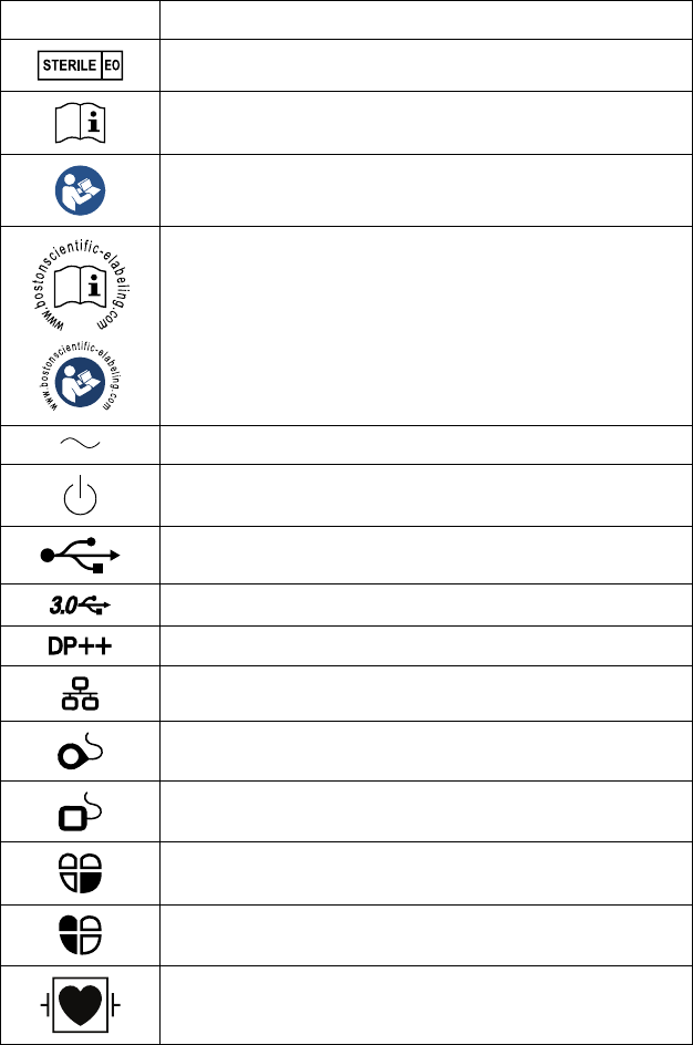
59
Table 4. Symbols on Devices and Packaging (continued)
Symbol Description
Sterilized using ethylene oxide
Consult instructions for use
Follow instructions for use
Follow instructions for use; see
www.bostonscientific-elabeling.com
Alternating current
The power button on the left side of the Programmer, which is
represented by the Standby symbol
USB 2.0
USB 3.0
DisplayPort
Local Area Network (LAN) Port
Model 3203 S-ICD Telemetry Wand
Model 6395 Telemetry Wand
PSA LV
PSA RA, RV
Defibrillation-proof type CF applied part
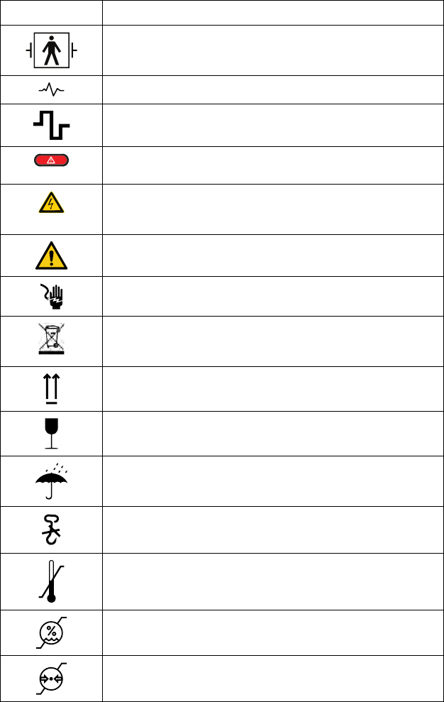
60
Table 4. Symbols on Devices and Packaging (continued)
Symbol Description
Defibrillation-proof type BF applied part
ECG cable connector
Future connection
Red STAT button on Programmer provides commands for low
voltage and high voltage rescue
Warning, electricity–Do not touch the connector terminals in the
Programmer battery compartment while removing or replacing
the battery as an electrical charge is present
ISO 7010-W001 general warning symbol for ECG connector on
the Programmer
Indicates the risk of electric shock; (do not touch contacts inside
battery compartment); refer servicing to Boston Scientific
Waste, Electrical, and Electronic Equipment (WEEE); iIndicates
separate collection for electrical and electronic equipment (i.e., do
not throw this device in the trash)
This side up
Fragile, handle with care
Keep dry
Do not use hooks
Temperature limitation
Humidity limitation
Atmospheric pressure limitation

61
Table 4. Symbols on Devices and Packaging (continued)
Symbol Description
Recycle box
MR Unsafe
Battery indicator symbol
Bluetooth®
DC power connection
SAFETY, COMPLIANCE, AND COMPATIBILITY
STANDARDS
The following standards apply to the LATITUDE Programming System.
Safety Standards
The LATITUDE Programming System has been tested and found to comply
with applicable safety portions of the following standards:
• IEC 60601-1:/A1:2012
• IEC 80001-1:2010
• ANSI/AAMI ES60601-1:2005(R)2012
• EN 60601-1:2006 + A1:2013 1
• CAN/CSA-C22 No. 60601-1:2014
Electromagnetic Compatibility Standards
The LATITUDE Programming System has been tested and found to comply
with the applicable portions of the FCC and IEC electromagnetic compatibility
(EMC) standards:
• FCC Part 15.209:2016 + 15.207:2016 + 15.249:2016
• IEC 60601-1-2:2014
Radio Spectrum Compliance Standards
The LATITUDE Programming System complies with the applicable portions of
the following radio spectrum compliance standards:
• EN 302 195-2 V1.1.1:2004
62
• EN 300 220-2 V2.4.1:2012
• EN 301 489-1 V1.9.2:2011
• EN 301 489-3 V1.6.1:2013
• EN 301 489-17 V2.2.1 2012
• EN 301 489-27 V1.1.1 2004
• EN 301 489-31 V1.1.1 2005
NOTE: Use special precautions regarding EMC during the installation and the
use of the LATITUDE Programming System, according to the EMC instructions
given throughout this manual. Refer to the details about the LATITUDE
Programming System electromagnetic emissions and immunity in Table 6
LATITUDE Programming System Nominal Specifications on page 66 and Table
7 Radio Nominal Specifications on page 68.
NOTE: Use caution when using RF portable and mobile telephony equipment
in close proximity to the LATITUDE Programming System. Refer to the details
about the LATITUDE Programming System electromagnetic immunity in Table
8 Network and Connectivity Specifications on page 69.
Electromagnetic Emissions and Immunity
IEC 60601–1–2:2014 Information
This equipment has been tested and found to comply with the applicable limits
for Class A medical devices in a professional healthcare facility environment to
ANSI/AAMI/IEC 60601-1-2:2014 [or BS EN 60601-1-2:2015 or Active
Implantable Medical Device Directive 90/385/EEC]. This testing shows the
device provides reasonable protection against harmful interference in a typical
medical installation. However, there is no guarantee that interference will not
occur in a particular installation.
Federal Communications Commission (FCC) Information
This device complies with Title 47, Part 15 of the FCC rules. Operation is
subject to the following two conditions:
• This device may not cause harmful interference.
• This device must accept any interference received, including interference
that may cause undesired operation.
This transmitter is authorized by rule under the Medical Device
Radiocommunication Service (in part 95 of the FCC Rules) and must not cause
harmful interference to stations operating in the 400.150-406.000 MHz band in
the Meteorological Aids (i.e., transmitters and receivers used to communicate
weather data), the Meteorological Satellite, or the Earth Exploration Satellite
Services and must accept interference that may be caused by such stations,
including interference that may cause undesired operation. This transmitter
shall be used only in accordance with the FCC Rules governing the Medical
Device Radiocommunication Service. Analog and digital voice communications
are prohibited. Although this transmitter has been approved by the Federal
Communications Commission, there is no guarantee that it will not receive

63
interference or that any particular transmission from this transmitter will be free
from interference.
CAUTION: No modification of this equipment is allowed unless approved by
Boston Scientific. Changes or modifications not expressly approved by Boston
Scientific could void the user’s authority to operate the equipment.
The electromagnetic emissions and immunity information is provided in Table 5
Guidance and Manufacturer’s Declaration—Electromagnetic Compatibility on
page 63.
Table 5. Guidance and Manufacturer’s Declaration—Electromagnetic
Compatibility
The LATITUDE Programming System, Model 3300, is suitable for use in
professional health care facility environments. The customer or the user of this
system should assure that it is used in such an environment.
Test Compliance Electromagnetic
environment—guidance
Protection of radio
services and other
equipment
CISPR 11
Group 1
Class A
The LATITUDE
Programming System,
Model 3300, uses RF
energy only for its
intended uses in
communication with the
implanted device or
connectivity functions. Its
RF emissions are very low
and are not likely to cause
any interference in nearby
electronic equipment.
Protection of the public
mains network
CISPR 11 Class A
IEC 61000-3-2
IEC 61000-3-3
The LATITUDE
Programming System,
Model 3300, is suitable for
use in professional health
care facility environments.
Electrostatic Discharge ± 8 kV contact
± 2 kV, ± 4 kV, ± 8 kV, and
± 15 kV air
Radiated RF EM field 3 V/m from 80 MHz to 2.7
GHz
Proximity fields from RF
wireless communications
equipment
MHz: 27 V/m
430 - 470 MHz: 28 V/m
704 - 787 MHz: 9 V/m
800 - 960 MHz: 28 V/m
1700 - 1900 MHz: 28 V/m
2400 - 2570 MHz: 28 V/m
5100 - 5800 MHz: 9 V/m
Rated power frequency
magnetic field
30 A/m

64
Table 5. Guidance and Manufacturer’s Declaration—Electromagnetic
Compatibility (continued)
The LATITUDE Programming System, Model 3300, is suitable for use in
professional health care facility environments. The customer or the user of this
system should assure that it is used in such an environment.
Test Compliance Electromagnetic
environment—guidance
Electrical fast transients/
bursts
± 2 kV input AC power
± 1 kV SIP/SOP
Surges line-to-line ± 0.5 kV, ± 1 kV input AC
power
Surges line-to-ground ± 0.5 kV, ± 1 kV, ± 2 kV
input AC power
Conducted disturbances
induced by RF fields
3 V/m from 0.15 MHz to 80
MHz
6 V/m in ISM bands from
0.15 MHz to 80 MHz
The ISM bands between
0.15 MHz and 80 MHz are
6.765 MHz to 6.795 MHz
13.553 MHz to 13,567
MHz
26.957 MHz to 27.283
MHz
40.66 MHz to 40.70 MHz.
The amateur radio bands
between 0.15 MHz and 80
MHz are
1.8 MHz to 2.0 MHz
3.5 MHz to 4.0 MHz
5.3 MHz to 5.4 MHz
7.0 MHz to 7.3 MHz
10.1 MHz to 10.15 MHz
14.0 MHz to 14.2 MHz
18.07 MHz to 18,17 MHz
21.0 MHz to 21.4 MHz
24.89 MHz to 24.99 MHz
28.0 MHz to 29.7 MHz
50.0 MHz to 54.0 MHz.
Voltage dipsa0% UTfor 0.5 cycle at 0°,
45°, 90°, 135°, 180°, 225°,
270°, and 315°
0% UTfor 1 cycle and 70%
UTfor 25/30 cycles at 0°
Voltage interruptionsa0% UTfor 250/300 cycles
a. Voltage dips and interruptions: UTis the AC mains voltage prior to application of the test level.

65
LATITUDE PROGRAMMING SYSTEM SECURITY
Sensible security practices are needed to protect patient data and the
LATITUDE Programming System integrity when connected to a network. The
Programmer incorporates features that facilitate management of network
security. These features work in conjunction with the security practices of
hospitals and clinics to provide safe and secure operation of the Programmer
and protect the attached network.
NOTE: All patient data is encrypted on the Programmer internal hard drive,
and the Programmer has network security safeguards in place to prevent
malicious attacks.
Software
All installed software has been approved by Boston Scientific and general
purpose software installation is not permitted. This minimizes the potential for
vulnerabilities to be exposed. Internal software that runs the Programmer is
locked from change and is re-verified upon each execution. Whenever Boston
Scientific software updates are available, install them as soon as possible.
Programmer settings should only be modified per guidance from verified
Boston Scientific technical support or Health Care Delivery personnel.
Patient Data Management
Refer to the Patient Data Management Operator’s Manual (Model 3931) for
additional security information.
Network
Refer to the Network and Connectivity Operator’s Manual (Model 3924) for
additional networking and connectivity security information.
Unsupported Hardware
Unsupported hardware, including unsupported USB devices, is ignored by the
Programmer and is not accessed.
Security Vigilance
Boston Scientific continues to work with its partners to analyze emerging
threats and evaluate potential impact on the LATITUDE Programming System.
Physical Controls
Maintain good physical controls over the Programmer. Having a secure
physical environment prevents access to the internals of the Programmer. USB
devices connected to the Programmer should be controlled to limit potential
introduction of malware. Patient sensitive information may be stored on the
Programmer and appropriate precautions should be taken to secure the
Programmer from unauthorized access.

66
Compromised Programmer
If you believe that the Programmer has been compromised by a security threat,
turn off the Programmer, disconnect it from the network, then restart the
LATITUDE Programming System. Discontinue use of the Programmer if it fails
the start-up self test or does not operate as expected. For further assistance,
contact Boston Scientific using the information on the back cover of this
manual.
SPECIFICATIONS
Table 6. LATITUDE Programming System Nominal Specifications
Characteristic Nominal
Safety classification LATITUDE Programming System: Class I.
• ECG connection:
Type BF, defibrillation-protected
• Model 6395 Telemetry Wand connection:
Type BF, defibrillation-protected
• Model 3203 S-ICD Telemetry Wand connection:
Type BF, defibrillation-protected
• Conducted Telemetry cable:
Type BF, defibrillation-protected
• PSA cable connections:
Type CF, defibrillation-protected
• Ingress protection rating: IPX0
Dimensions Programmer without Stand:
30.7 cm (12.1 in) deep, 34 cm (13.4 in) wide,
12.5 cm (4.9 in) high
With Stand (in handle up position):
24.9 cm (9.8 in) deep, 35.1 cm (13.8 in) wide,
31.8 cm (12.5 in) high
Weight (approximate) Programmer (without battery or stand):
3.58 kg (7.9 lbs)
Battery: 0.45 kg (1.0 lb)
Stand: 1.28 kg (2.75 lb)
Model 6689 power adapter
power rating
100–120 V, 50/60 Hz, 3.8 A
220–240 V, 50 Hz, 1.9 A
Maximum Output
Cord length
Dimensions
456 W
1.53 m (5 ft)
14.94 cm x 6.26 cm x 3.35 cm
(5.88 in x 2.46 in x 1.32 in)

67
Table 6. LATITUDE Programming System Nominal Specifications (continued)
Characteristic Nominal
Power cord (3 prong) 2.4 m (8 ft) 100–240 V
Duty cycle Continuous
Operating temperature 10 °C to 32 °C (50 °F to 90 °F)
Transport and storage
temperature
-20 °C to 60 °C (-4 °F to 140 °F)
Operating humidity 25% to 85%
Transport and storage
humidity
25% to 85%
Operating altitude ≤ 3,000 m (≤ 9,843 ft)
Transport and storage
atmospheric pressure
50 kPa to 106 kPa (7.252 psi to 15.374 psi)
External support; pen
drives, printer
(3) USB 2.0 ports;
(1) USB 3.0 port
External digital monitor
support
DisplayPort digital connector;
Monitor must comply with emissions standard CISPR
32.
Battery type 7.5 A hr Lithium-ion, Totex PN U80221-3
Ethernet:
Data Interface Data Interface RJ-45 Ethernet Connector
Data Modulation IEEE 802.3u, 100 Mbps full duplex and half duplex on
100BASE-T
IEEE 802.3ab, 1 Gbps full duplex and half duplex on
1000BASE-T
Wi-Fi IEEE 802.11g, 802.11n, and 802.11ac
ECG cable, Model 3153 3.9 m to 4.3 m (12.7 ft to 14.0 ft)
ECG performance:
Minimum amplitude
detected
4.56 μV
Lead selection I, II, III, aVR, aVL, aVF, V
Intrinsic and paced
ventricular rate display
30 bpm to 120 bpm ± 4 bpm on a three-beat average
basis; 120 bpm to 240 bpm ± 8 bpm on a three-beat
average basis

68
Table 6. LATITUDE Programming System Nominal Specifications (continued)
Characteristic Nominal
Input impedance > 2.5 mΩ
Electrode offset tolerance 300 mV
Storage resolution 800 samples/sec, 4.56 μV
Filter settings for storage
resolution
ON: 0.5 Hz to 40 Hz, ± 0.2 dB, with 50 and 60 Hz notch
filters
OFF: 0.5 Hz to 100 Hz, ± 0.2 dB, flat response, without
50 and 60 Hz notch filters; 0.05 Hz to 100 Hz, + 0.2 dB/-
3.0 dB, without 50 and 60 Hz notch filters
Gain settings 0.5, 1, 2, 5, 10, 20 mm/mV ± 25%
Electrical Safety Testing-
Reference for testing
according to the IEC
62353 (Installation,
Maintenance, Repair)a b
Earthbond testing
(Groundbond testing)
≤ 300 mΩ including power cable not exceeding 3 meters
Equipment leakage, direct
method (accessible parts)
≤ 500 μA
Patient leakage current,
direct method
Model 6395 Telemetry Wand (BF) ≤ 5000 μA,
ECG (BF) ≤ 5000 μA,
PSA (CF) ≤50 μA
Safety Feature
Defibrillator protection Up to 5000 V (400 J)
a. For questions regarding operation or repair of the LATITUDE Programming System, contact
Boston Scientific using the information on the back cover of this manual. The LATITUDE
Programming System must be serviced by Boston Scientific personnel only.
b. After successfully completing safety testing, verify the LATITUDE Programming System continues
to meet the essential performance as defined in the beginning of this manual.
Table 7. Radio Nominal Specifications
Characteristic Nominal
ZIP MICS Telemetry (MICS/MedRadio)
Frequency Band
Bandwidth
Modulation
Radiated power
402 – 405 MHz
Medical Implant Communication Service (MICS)
Medical Device Radio Communication Service
(MedRadio)
< 145 kHz
FSK
< 25 µW E.I.R.P.

69
Table 7. Radio Nominal Specifications (continued)
Characteristic Nominal
ZIP Telemetry (ISM)
Frequency band
Bandwidth
Modulation
Radiated power
902 – 928 MHz
Industrial, Scientific, and Medical radio band (ISM)
< 650 kHz
ASK
< 0.75 mW E.I.R.P.
Model 6395 Wand Telemetry (Inductive)
Frequency band
Bandwidth
Modulation
Radiated power
Transmit: 20 kHz
Receive: 0 – 100 kHZ
< 125 kHz
OOK/QPSK
< 13.7 dBµV/m @ 3 m
Bluetooth®
Frequency band
Bandwidth
Modulation
Radiated power
2400.0 – 2483.5 MHz
< 1.4 MHz
GFSK, π/4–DQPSK, 8DPSK
< 9.6 mW E.I.R.P.
Wi-Fi 2.4 GHz
Frequency band
Bandwidth
Modulation
Radiated power
2400.0 – 2483.5 MHz
20/40 MHz
IEEE 802.11b/g/n
< 80 mW E.I.R.P.
Wi-Fi 5 GHz
Frequency band
Bandwidth
Modulation
Radiated power
5150 – 5350 MHz
5470 – 5725 MHz
5725 – 5850 MHz
20/40/80 MHz
IEEE 802.11a/n/ac
< 50 mW E.I.R.P.
Table 8. Network and Connectivity Specifications
Characteristic Specification
Required Characteristics of IT Network
Ethernet IEEE 802.3u, 100 Mbps full duplex and half duplex on
100BASE-TX
IEEE 802.3ab, 1 Gbps full duplex and half duplex on
1000BASE-T
Wi-Fi IEEE 802.11g, 802.11n, and 802.11ac

70
Table 8. Network and Connectivity Specifications (continued)
Characteristic Specification
Hazardous situations
resulting from network
failure
None
Required Configuration of IT Network
Ethernet Dynamic or Static IP addressing
Wi-Fi Dynamic IP addressing, using IEEE 802.11g, 802.11n,
or 802.11ac specifications to connect to networks that
are public/unsecured, WPA-PSK, or WPA2-PSK
Ethernet MAC address The network MAC address can be displayed and the
host name is editable
Internet protocol IPv4
Dynamic Host
Configuration Protocol
(DHCP) mode
Both manual and automatic DHCP modes are
supported
Wi-Fi MAC address Displayable
WARRANTY INFORMATION
A warranty card is packaged with the LATITUDE Programming System. Unless
otherwise agreed, the LATITUDE Programming System remains the property
of Boston Scientific and Boston Scientific must perform all necessary servicing
and repair work. For additional warranty information, contact Boston Scientific
using the warranty information on the card.

Boston Scientific Corporation
4100 Hamline Avenue North
St. Paul, MN 55112-5798 USA
www.bostonscientific.com
1.800.CARDIAC (227.3422)
+1.651.582.4000
©2017 Boston Scientific Corporation or its affiliates.
All rights reserved.
359487-001 EN US 2017-03
FCC ID: ESCCRM330017 (Contains FCC ID: PD97265NG)
*359487-001*