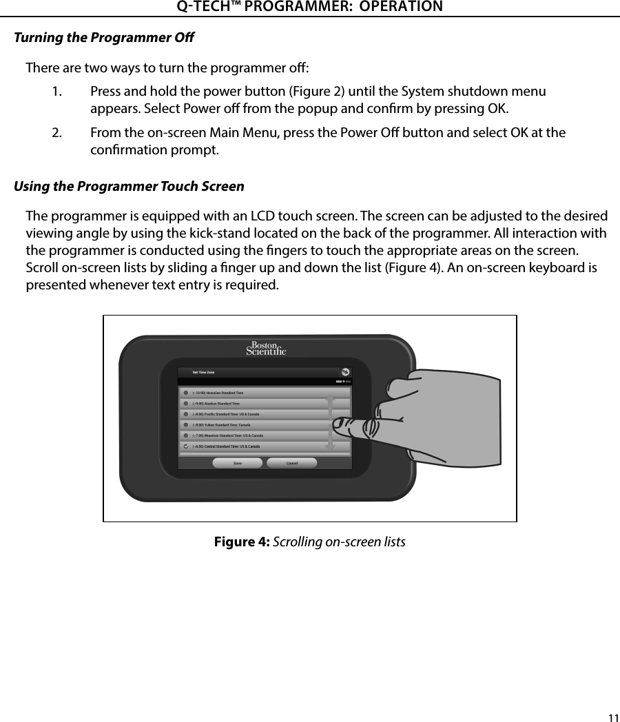
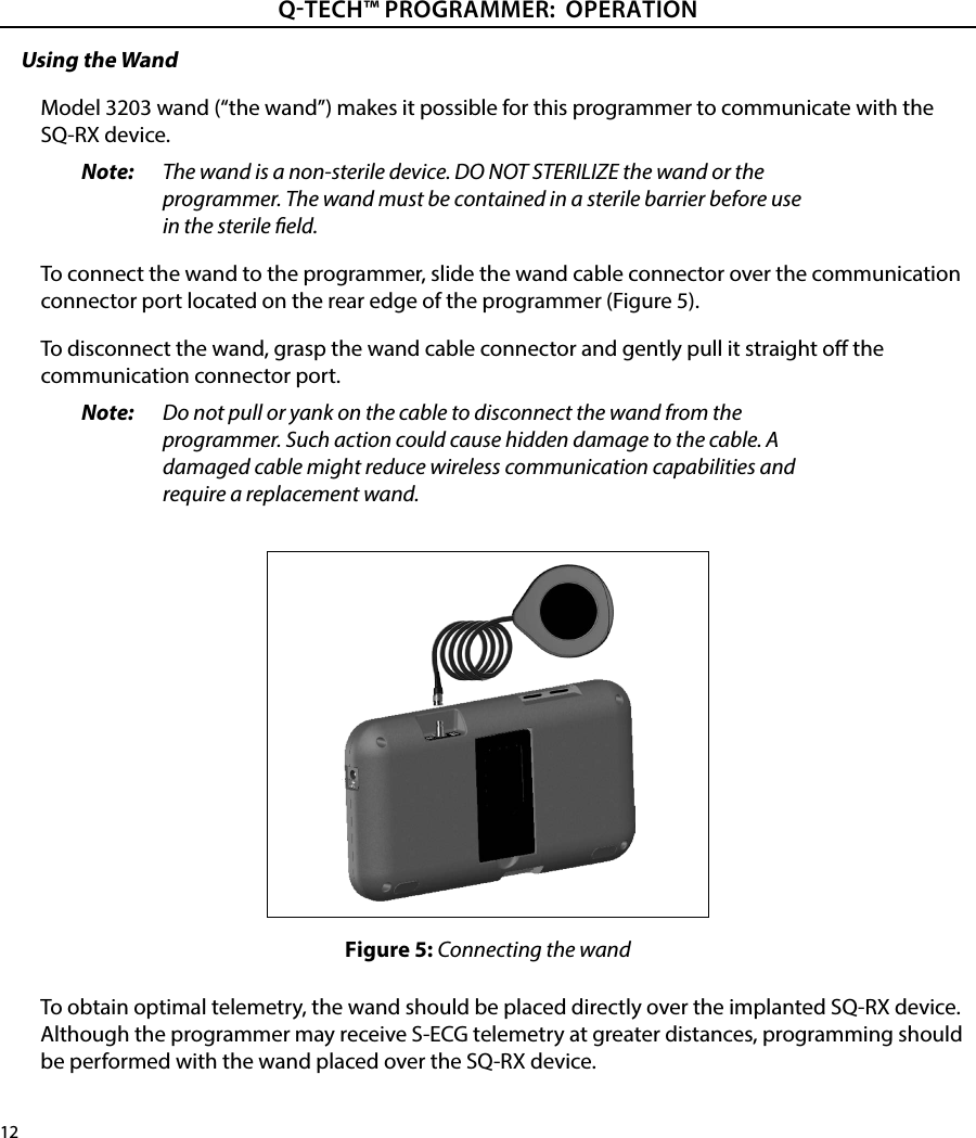
Boston Scientific CRM70514 Bluetooth Module User Manual
Boston Scientific Corporation Bluetooth Module Users Manual
UserManual.wiki
>
Boston Scientific
>
CRM70514 User Manual
Users Manual
Navigation menu
Upload a User Manual
Namespaces
Wiki Guide
HTML
PDF
Info
Views
User Manual
Discussion / Help
Navigation
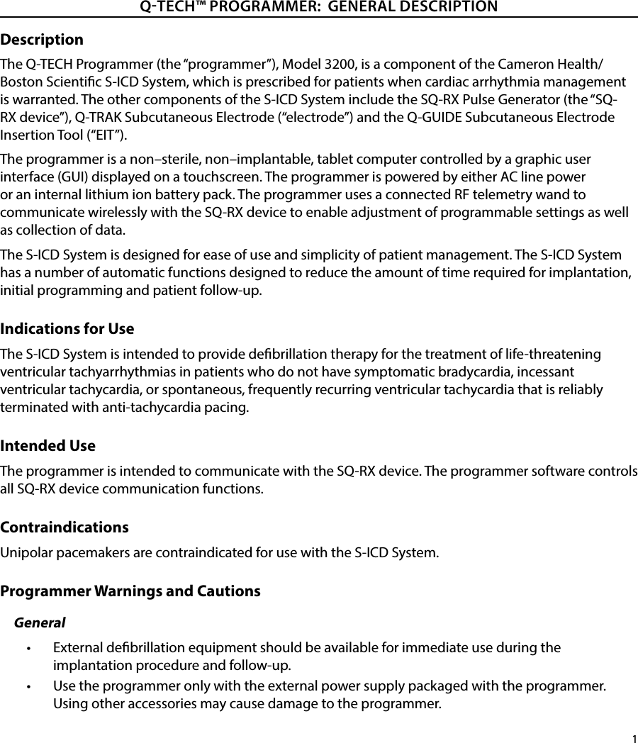
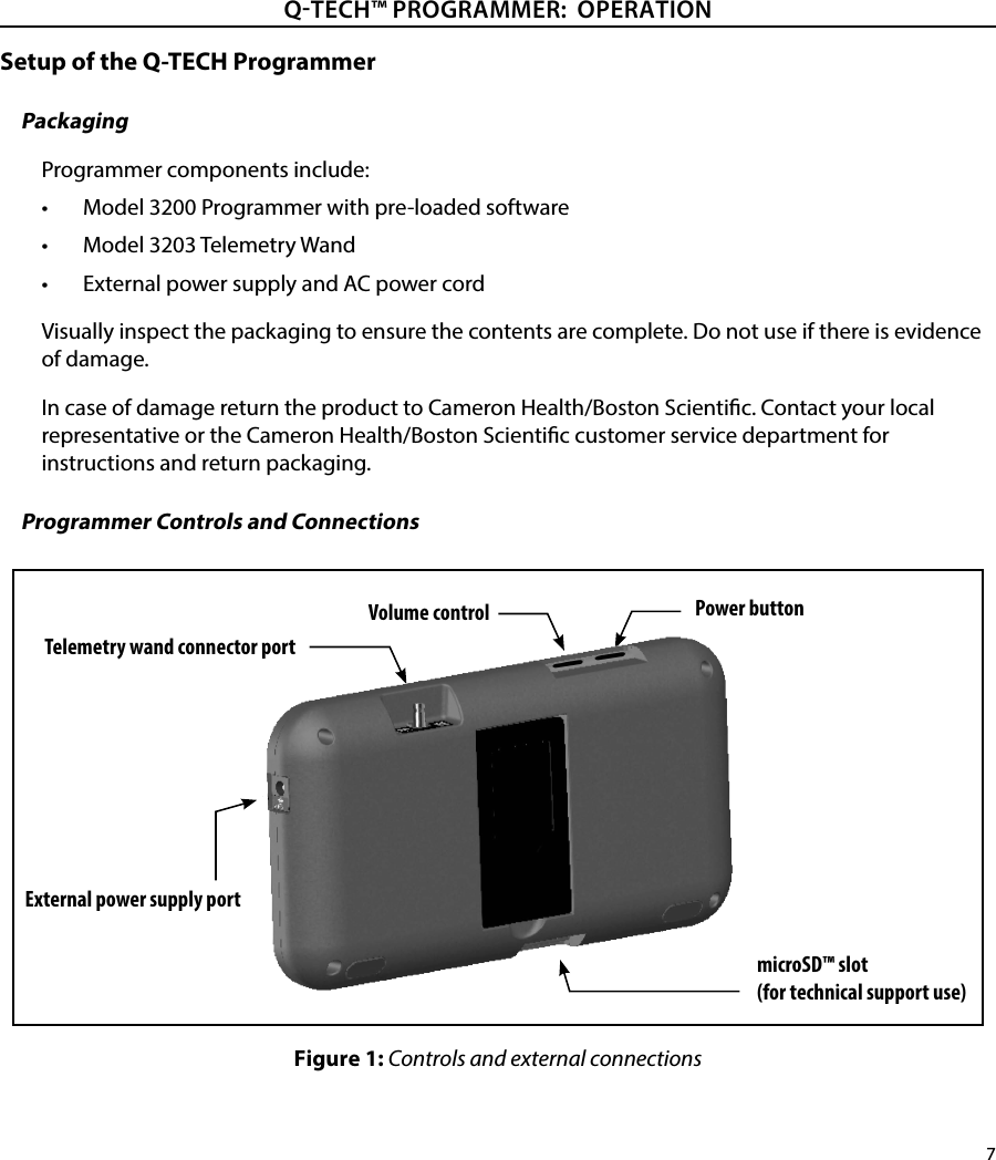
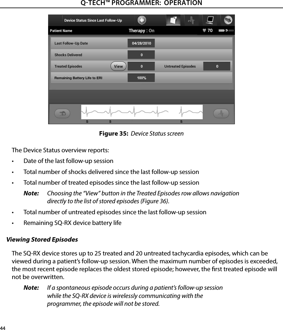
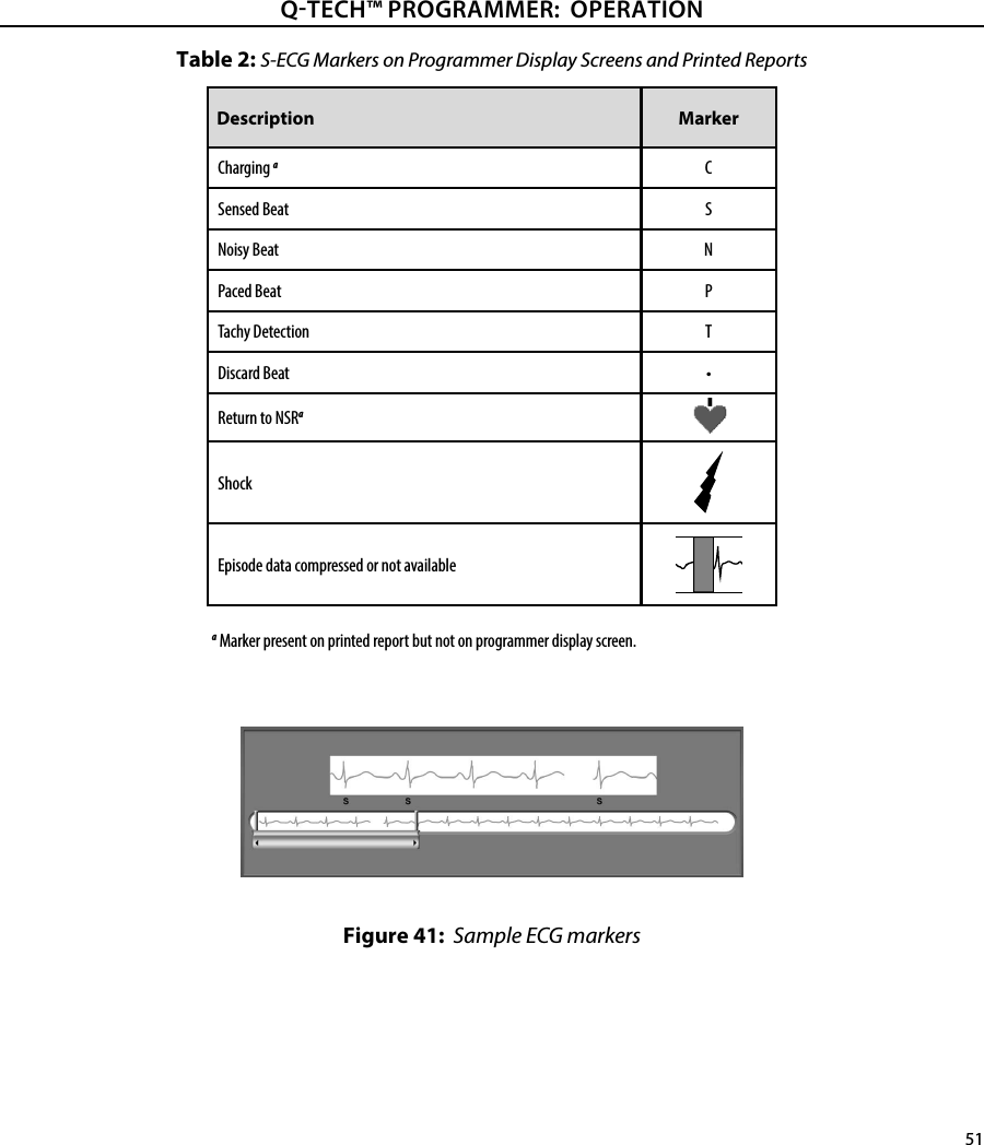

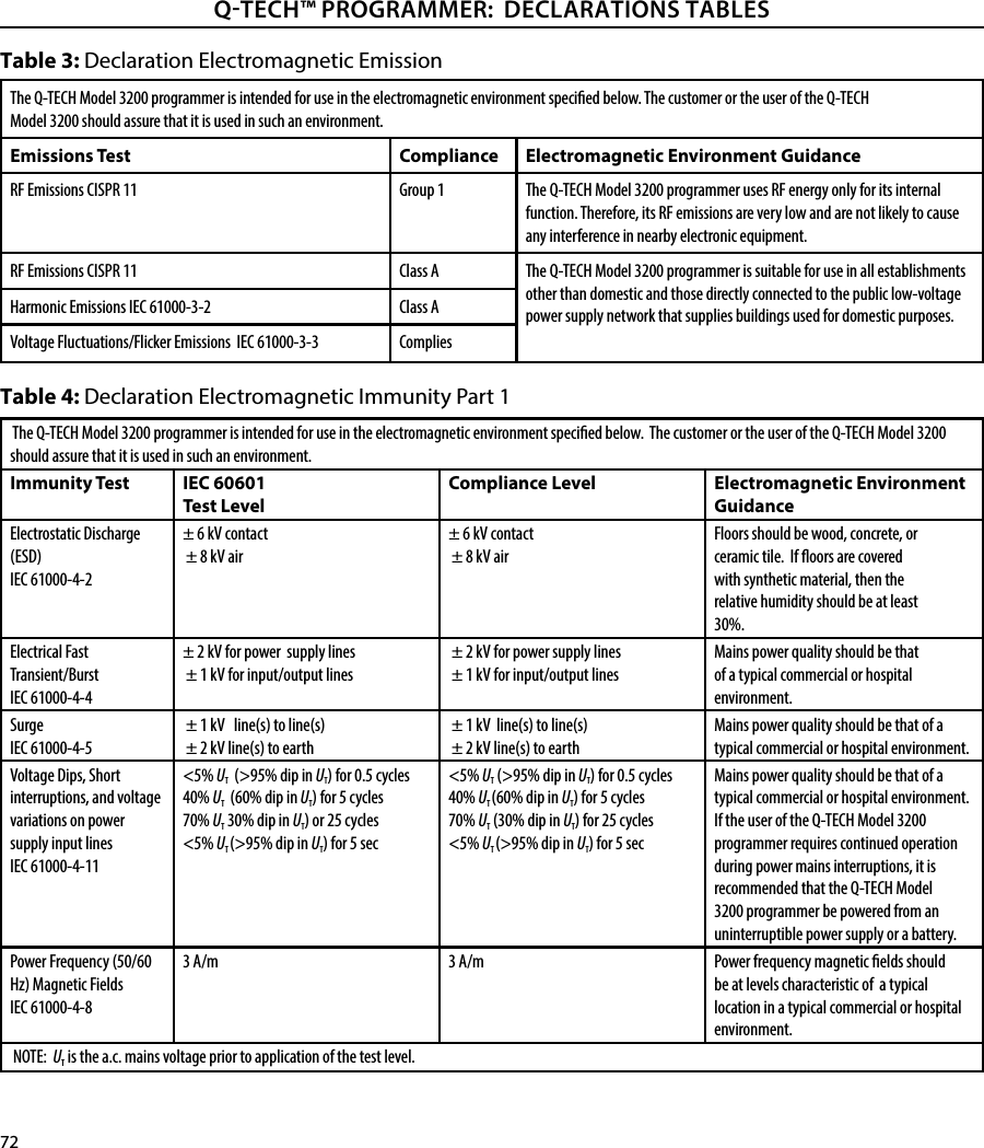
![73QTECH™ PROGRAMMER: DECLARATIONS TABLESTable 5: Declaration Electromagnetic Immunity Part 2The Q-TECH Model 3200 programmer is intended for use in the electromagnetic environment specied below. The customer or the user of the Q-TECH Model 3200 should assure that it is used in such an environment.Immunity Test IEC 60601 Test LevelCompliance LevelElectromagnetic Environment GuidanceConducted RFIEC 61000-4-63 Vrms150 kHz to80 MHz3 V Portable and mobile RF communications equipment should be used no closer to any part of the Q-TECH Model 3200 programmer, including cables, than the recommended separation distance calculated from the equation applicable to the frequency of the transmitter.Recommended Separation Distance3,5V1√ Pd = []3,5E1√ Pd = []7E1√ Pd = []80 MHz to 800 MHz800 MHz to 2.5 GHz150 KHz to 80 MHzwhere P is the maximum output power rating of the transmitter in watts (W) according to the transmitter manufacturer and d is the recommended separation distance in meters (m).Field strengths from xed RF transmitters, as determined by an electromagnetic site survey,a should be less than the compliance level in each frequency range.bInterference may occur in the vicinity of equipment marked with the following symbol:Radiated RFIEC 61000-4-33 V/m80 MHz to2.5 GHz3 V/mNote 1: At 80 MHz and 800 MHz, the higher frequency range applies.Note 2: These guidelines may not apply in all situations. Electromagnetic propagation is aected by absorption and reection from structures, objects and people.a Field strengths from xed transmitters, such as base stations for radio (cellular/cordless) telephones and land mobile radios, amateur radio, AM and FM radio broadcast and TV broadcast cannot be predicted theoretically with accuracy. To assess the electromagnetic environment due to xed RF transmitters, an electromagnetic site survey should be considered. If the measured eld strength in the location in which the Q-TECH Model 3200 is used exceeds the applicable RF compliance level above, the Q-TECH Model 3200 should be observed to verify normal operation. If abnormal performance is observed, additional measures may be necessary, such as reorienting or relocating the Q-TECH Model 3200.b Over the frequency range 150 kHz to 80 MHz, eld strengths should be less than 3 V/m](https://usermanual.wiki/Boston-Scientific/CRM70514/User-Guide-2483234-Page-79.png)
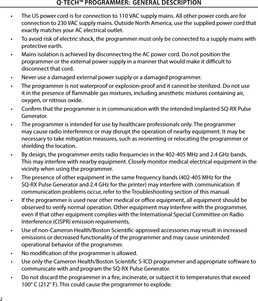
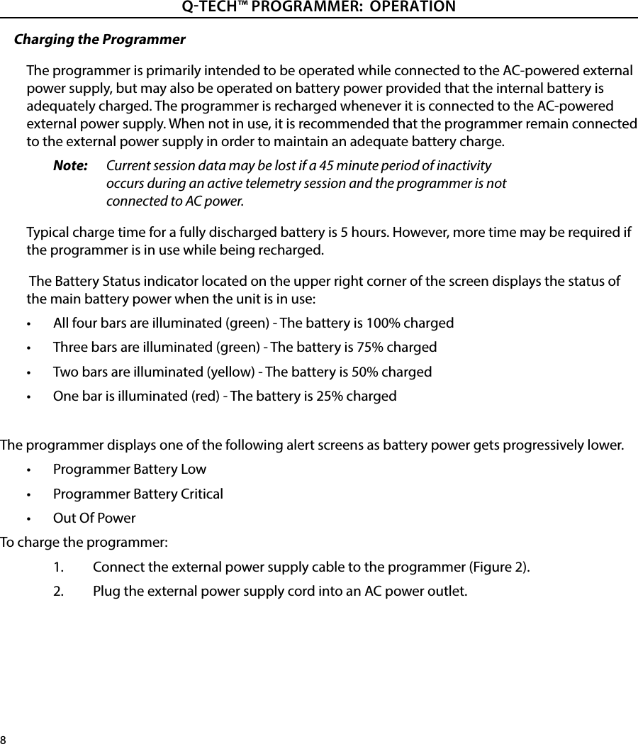
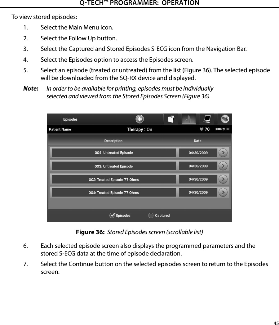
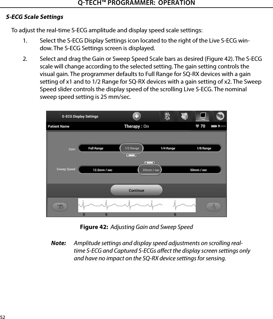
![74QTECH™ PROGRAMMER: DECLARATIONS TABLESTable 8: EMI/RFI Information: Programmer–to–printer (Bluetooth®)Specication Bluetooth® 4.0 wireless technologyFrequency band 2.402-2.480 GHzModulation type GFSK, π/4-DQPSK, 8DPSKRadiated power <100 mWBandwidth < 1 MHzTable 6: Recommended Separation Distances Recommended separation distances between portable and mobile RF communications equipment and the Q-TECH Model 3200 programmerThe Q-TECH Model 3200 programmer is intended for use in an electromagnetic environment in which radiated RF disturbances are controlled. The customer or the user of the Q-TECH Model 3200 programmer can help prevent electromagnetic interference by maintaining a minimum distance between portable and mobile RF communications equipment (transmitters) and the Q-TECH Model 3200 programmer as recommended below, according to the maximum output power of the communications equipment.Rated maximum output power of transmitter WSeparation distance according to frequency of transmitter m150 KHz to 80 MHz 3,5V1√ Pd = []80 MHz to 800 MHz 3,5E1√ Pd = [] 800 MHz to 2.5 GHz 0.01 0.117 0.117 0.2330.1 0.369 0.369 0.7381 1.17 1.17 2.3410 3.69 3.69 7.38100 11.7 11.7 23.3For transmitters rated at a maximum output power not listed above, the recommended separation distance d in metres (m) can be estimated using the equation applicable to the frequency of the transmitter, where p is the maximum output power rating of the transmitter in watts (W) according to the transmitter manufacturer. Note 1: At 80 MHz and 800 MHz, the separation distance for the higher frequency range applies.Note 2: These guidelines may not apply in all situations. Electromagnetic propagation is aected by absorption and reection from structures, objects and people.7E1√ Pd = []Table 7: EMI/RFI Information: Programmer–to–pulse generatorSpecication Medical Implant Communications Service (MICS)Frequency band 402-405 MHzModulation type FSKRadiated Power <25 μWBandwidth < 300 KHz](https://usermanual.wiki/Boston-Scientific/CRM70514/User-Guide-2483234-Page-80.png)