Boston Scientific CRM70514 Bluetooth Module User Manual
Boston Scientific Corporation Bluetooth Module Users Manual
Users Manual
Q-TECH™ PROGRAMMER
A COMPONENT OF THE S-ICD® SYSTEM
USER’S MANUAL
Model 3200
Physician must be trained or
experienced in device implant
and follow-up procedures.
© Copyright 2014 Boston Scientic or its aliates.
All rights reserved.
Limited Software License and Equipment Use.
S-ICD®, SQ-RX®, and Q-TRAK® are all registered trademarks of Cameron Health, Inc.
Q-GUIDE™ and Q-TECH™ are all trademarks of Cameron Health, Inc.
The Bluetooth® word mark and logos are registered trademarks owned by Bluetooth SIG, Inc. and any use of
such marks is under license.
microSD is a trademark or registered trademark of SD-3C, LLC.
Manuals or other written documentation may not be copied or distributed without Cameron Health, Inc.
authorization.
Cameron Health, Inc.
4100 Hamline Avenue North
St. Paul, MN 55112-5798 USA
1.800.CARDIAC (227.3422)
+1.651.582.4000
www.cameronhealth.com
This literature is intended for use by professionals trained or experienced in device implant and/or follow-up
procedures.
TABLE OF CONTENTS
GENERAL DESCRIPTION
Description ................................................................................................................................1
Indications for Use ....................................................................................................................1
Intended Use .............................................................................................................................1
Contraindications .....................................................................................................................1
Programmer Warnings and Cautions ......................................................................................1
General .................................................................................................................................................................... 1
Electrostatic Discharge (ESD) ..........................................................................................................................3
S-ICD System Warnings and Cautions .....................................................................................3
General .................................................................................................................................................................... 3
Use of Other Medical Therapies/Diagnostic Procedures ......................................................................4
Electromagnetic Interference (EMI) Outside the Hospital Environment ........................................5
S-ICD System Clinical Investigation ..............................................................................................................5
Potential Adverse Events ..................................................................................................................................6
OPERATION
Setup of the Q-TECH Programmer ...........................................................................................7
Packaging ...............................................................................................................................................................7
Programmer Controls and Connections .....................................................................................................7
Charging the Programmer ...............................................................................................................................8
Using the Q-TECH Programmer................................................................................................9
Turning the Programmer On ........................................................................................................................... 9
Changing the Programmer Volume Level ............................................................................................... 10
Placing the Programmer in Suspend Mode ............................................................................................ 10
Turning the Programmer O........................................................................................................................ 11
Using the Programmer Touch Screen ....................................................................................................... 11
Using the Wand ................................................................................................................................................. 12
Navigation .......................................................................................................................................................... 13
Screen Header ................................................................................................................................................... 13
Navigation Bar ................................................................................................................................................... 14
Restarting the Programmer .......................................................................................................................... 14
Conguring the Q-TECH Programmer .................................................................................. 16
Conguring Programmer Settings ............................................................................................................. 16
Date and Time Format .................................................................................................................................... 18
Time Zone ........................................................................................................................................................... 18
Language Preference ...................................................................................................................................... 19
Printer Selection ............................................................................................................................................... 19
Programmer Software Version .................................................................................................................... 22
Modes of Operation for the Q-TECH Programmer ............................................................... 22
Online Behavior ................................................................................................................................................ 22
Oine Behavior ................................................................................................................................................ 23
Modes of Operation for the SQ-RX Device ........................................................................... 24
Shelf Mode .......................................................................................................................................................... 24
Therapy On Mode ............................................................................................................................................ 24
Therapy O Mode ............................................................................................................................................ 24
Connecting and Disconnecting from the SQ-RX Device ..................................................... 25
Scanning For SQ-RX Devices ........................................................................................................................ 25
Connecting to the SQ-RX Device ................................................................................................................ 27
Connecting to an SQ-RX Device in Shelf Mode: .................................................................................... 27
Ending a Patient Session ............................................................................................................................... 28
Programming the SQ-RX Device at Implant ........................................................................ 30
Entering Electrode Information .................................................................................................................. 30
Creating the Patient Chart ............................................................................................................................ 32
Automatic Setup ............................................................................................................................................... 34
Programming Therapy Parameters ............................................................................................................ 37
Debrillation Testing ....................................................................................................................................... 40
Performing an SQ-RX Follow-up ........................................................................................... 43
Sensing Conguration and Automatic Setup ........................................................................................ 43
Viewing SQ-RX Device Status ...................................................................................................................... 43
Viewing Stored Episodes ............................................................................................................................... 44
Printing Reports from the Programmer ............................................................................... 46
Printing Reports ................................................................................................................................................ 46
Summary Report .............................................................................................................................................. 47
Captured S-ECG Report .................................................................................................................................. 48
OPERATION (continued)
Episodes Report ................................................................................................................................................ 49
S-ECG Features ....................................................................................................................... 50
S-ECG Rhythm Strip Markers ........................................................................................................................ 50
S-ECG Scale Settings ....................................................................................................................................... 52
Capture and View S-ECG Strips .................................................................................................................... 53
Utilities Menu ......................................................................................................................... 54
Acquire Reference S-ECG ............................................................................................................................... 55
Capture All Sense Vectors.............................................................................................................................. 56
Beeper Control .................................................................................................................................................. 57
Manual Setup..................................................................................................................................................... 58
Smart Charge ..................................................................................................................................................... 61
Additional Programmer Functions ....................................................................................... 63
Rescue Shock ..................................................................................................................................................... 63
Manual shock ..................................................................................................................................................... 65
S-ICD System Magnet Model 4520 ............................................................................................................ 65
MAINTENANCE
Charging the Programmer ............................................................................................................................66
Cleaning the Programmer............................................................................................................................. 66
Service .................................................................................................................................................................. 66
Maintenance Check ......................................................................................................................................... 67
Safety Measurements ..................................................................................................................................... 67
Programmer End of Life ................................................................................................................................ 67
TROUBLESHOOTING
Inability to Print ................................................................................................................................................ 68
No Printer Available ......................................................................................................................................... 68
Touch Screen Inactive while Connected to AC Power ........................................................................ 68
Loss of Communication with Printer .........................................................................................................68
Inability to Communicate With the SQ-RX Device ............................................................................... 69
COMPLIANCE STATEMENTS
Federal Communications Commission (FCC) US .................................................................................. 70
Essential Performance .................................................................................................................................... 70
EMI/RFI ................................................................................................................................................................. 71
DECLARATIONS TABLES
Declaration Electromagnetic Emission .................................................................................................... 72
Declaration Electromagnetic Immunity Part 1 ...................................................................................... 72
Declaration Electromagnetic Immunity Part 2 ...................................................................................... 73
Recommended Separation Distances ...................................................................................................... 74
EMI/RFI Information: Programmer–to–pulse generator .................................................................... 74
EMI/RFI Information: Programmer–to–printer (Bluetooth®) ............................................................... 74
SPECIFICATIONS
Product Guidelines .......................................................................................................................................... 75
Specications ..................................................................................................................................................... 75
Nominal Specications .................................................................................................................................. 76
DEFINITION OF PACKAGE LABEL SYMBOLS
Packaging Symbols: Q-TECH Programmer .............................................................................................. 77
Packaging Symbols: Q-TECH Programmer Wand ................................................................................. 77
WARRANTY
Limited Warranty .............................................................................................................................................. 78

1
QTECH™ PROGRAMMER: GENERAL DESCRIPTION
Description
The Q-TECH Programmer (the “programmer”), Model 3200, is a component of the Cameron Health/
Boston Scientic S-ICD System, which is prescribed for patients when cardiac arrhythmia management
is warranted. The other components of the S-ICD System include the SQ-RX Pulse Generator (the “SQ-
RX device”), Q-TRAK Subcutaneous Electrode (“electrode”) and the Q-GUIDE Subcutaneous Electrode
Insertion Tool (“EIT”).
The programmer is a non–sterile, non–implantable, tablet computer controlled by a graphic user
interface (GUI) displayed on a touchscreen. The programmer is powered by either AC line power
or an internal lithium ion battery pack. The programmer uses a connected RF telemetry wand to
communicate wirelessly with the SQ-RX device to enable adjustment of programmable settings as well
as collection of data.
The S-ICD System is designed for ease of use and simplicity of patient management. The S-ICD System
has a number of automatic functions designed to reduce the amount of time required for implantation,
initial programming and patient follow-up.
Indications for Use
The S-ICD System is intended to provide debrillation therapy for the treatment of life-threatening
ventricular tachyarrhythmias in patients who do not have symptomatic bradycardia, incessant
ventricular tachycardia, or spontaneous, frequently recurring ventricular tachycardia that is reliably
terminated with anti-tachycardia pacing.
Intended Use
The programmer is intended to communicate with the SQ-RX device. The programmer software controls
all SQ-RX device communication functions.
Contraindications
Unipolar pacemakers are contraindicated for use with the S-ICD System.
Programmer Warnings and Cautions
General
• External debrillation equipment should be available for immediate use during the
implantation procedure and follow-up.
• Use the programmer only with the external power supply packaged with the programmer.
Using other accessories may cause damage to the programmer.

2
QTECH™ PROGRAMMER: GENERAL DESCRIPTION
• The US power cord is for connection to 110 VAC supply mains. All other power cords are for
connection to 230 VAC supply mains. Outside North America, use the supplied power cord that
exactly matches your AC electrical outlet.
• To avoid risk of electric shock, the programmer must only be connected to a supply mains with
protective earth.
• Mains isolation is achieved by disconnecting the AC power cord. Do not position the
programmer or the external power supply in a manner that would make it dicult to
disconnect that cord.
• Never use a damaged external power supply or a damaged programmer.
• The programmer is not waterproof or explosion-proof and it cannot be sterilized. Do not use
it in the presence of ammable gas mixtures, including anesthetic mixtures containing air,
oxygen, or nitrous oxide.
• Conrm that the programmer is in communication with the intended implanted SQ-RX Pulse
Generator.
• The programmer is intended for use by healthcare professionals only. The programmer
may cause radio interference or may disrupt the operation of nearby equipment. It may be
necessary to take mitigation measures, such as reorienting or relocating the programmer or
shielding the location.
• By design, the programmer emits radio frequencies in the 402-405 MHz and 2.4 GHz bands.
This may interfere with nearby equipment. Closely monitor medical electrical equipment in the
vicinity when using the programmer.
• The presence of other equipment in the same frequency bands (402-405 MHz for the
SQ-RX Pulse Generator and 2.4 GHz for the printer) may interfere with communication. If
communication problems occur, refer to the Troubleshooting section of this manual.
• If the programmer is used near other medical or oce equipment, all equipment should be
observed to verify normal operation. Other equipment may interfere with the programmer,
even if that other equipment complies with the International Special Committee on Radio
Interference (CISPR) emission requirements.
• Use of non-Cameron Health/Boston Scientic-approved accessories may result in increased
emissions or decreased functionality of the programmer and may cause unintended
operational behavior of the programmer.
• No modication of the programmer is allowed.
• Use only the Cameron Health/Boston Scientic S-ICD programmer and appropriate software to
communicate with and program the SQ-RX Pulse Generator.
• Do not discard the programmer in a re, incinerate, or subject it to temperatures that exceed
100° C (212° F). This could cause the programmer to explode.

3
QTECH™ PROGRAMMER: GENERAL DESCRIPTION
• Do not disassemble or alter any parts of the programmer.
• Do not immerse the programmer in liquid of any kind. If the programmer does get wet, contact
customer service for information about returning the programmer to Cameron Health/Boston
Scientic. Do not attempt to dry the programmer in an oven, microwave, or dryer because this
poses a risk of overheating or explosion.
• Do not subject the programmer to temperatures outside of the -10° C to 55° C (14° F to 131°
F) storage range. Exposure to high temperatures may cause the programmer to overheat or
ignite, and may possibly reduce its performance and service life.
• Mishandling (such as dropping or crushing) could damage the programmer. If you suspect
damage to the programmer, contact your Cameron Health/Boston Scientic representative or
the customer service department for instructions and return packaging.
• The display on the programmer is made of glass or acrylic and could break if the programmer
is dropped or if it receives signicant impact. Do not use if screen is broken or cracked as this
could cause injury .
• Do not use the programmer adjacent to or stacked with other equipment. If adjacent or
stacked use is necessary, check the programmer for normal operation in that conguration.
• Contact your Cameron Health/Boston Scientic representative or the customer service
department for assistance or a replacement part.
Electrostatic Discharge (ESD)
The programmer may be aected by ESD. If ESD occurs and the programmer’s functionality is
aected, attempt to reset the programmer or contact your Cameron Health/Boston Scientic
representative or the customer service department for instructions.
• Do not touch or connect the telemetry wand to the programmer unless ESD precautionary
procedures are used.
S-ICD System Warnings and Cautions
Before using the S-ICD System, read and follow all warnings and cautions provided in this manual. Refer
to the SQ-RX Pulse Generator, Q-TRAK Electrode or Q-GUIDE Electrode Insertion Tool User’s Manuals for
information on implanting and explanting the S-ICD System.
The S-ICD System contains sterile products for single use only. Do not resterilize. Handle the
components of the S-ICD System with care at all times and maintain proper sterile technique.
General
• External debrillation equipment should be available for immediate use during the
implantation procedure and follow-up.

4
QTECH™ PROGRAMMER: GENERAL DESCRIPTION
• Placing a magnet over the SQ-RX Pulse Generator suspends arrhythmia detection and therapy
response. Removing the magnet resumes arrhythmia detection and therapy response.
• Battery depletion will eventually cause the SQ-RX Pulse Generator to stop functioning.
Debrillation and excessive numbers of charging cycles shorten the SQ-RX Pulse Generator’s
battery longevity.
• The S-ICD System has not been evaluated for pediatric use.
• The S-ICD System does not provide long-term bradycardia pacing, Cardiac Resynchronization
Therapy (CRT) or Anti-Tachycardia Pacing (ATP).
Use of Other Medical Therapies/Diagnostic Procedures
• External debrillation or cardioversion may damage the S-ICD System. Avoid placing the
debrillation paddles directly over the SQ-RX device or electrode.
• Cardio Pulmonary Resuscitation (CPR) may temporarily interfere with sensing and may cause
delay of therapy.
• Do not expose a patient with an implanted S-ICD System to diathermy. The interaction of
diathermy therapy with an implanted SQ-RX Pulse Generator can damage the SQ-RX Pulse
Generator and cause patient injury.
• Do not expose the patient to MRI scanning. MRI scanning can damage the SQ-RX Pulse
Generator and cause patient injury.
• Electrical interference or “noise” from sources such as electrosurgical and monitoring
equipment can interfere with the communication between the programmer and SQ-RX Pulse
Generator or cause inappropriate therapy. If interference occurs, move and reposition the
programmer or wand away from the source of the interference.
• Ionizing radiation therapy, such as radioactive cobalt, linear accelerators, and betatrons
may adversely aect the S-ICD System operation. Therapeutic ionizing radiation cannot be
immediately detected; however, it can damage the electronic components of the SQ-RX Pulse
Generator. To minimize the risks of ionizing radiation:
» Shield the SQ-RX Pulse Generator with a radiation-resistant material, regardless of the
distance between the SQ-RX Pulse Generator and the radiation beam.
» Do not project the radiation port directly at the SQ-RX Pulse Generator.
» Evaluate the S-ICD System operation after each radiation treatment.
• Lithotripsy and other therapeutic forms of ultrasound can damage the SQ-RX Pulse Generator.
If required, avoid direct ow of the pulse waves near the site of the implanted SQ-RX Pulse
Generator.

5
QTECH™ PROGRAMMER: GENERAL DESCRIPTION
• Use caution during ablation procedures. Program the S-ICD System to Therapy O. Keep the
current path (electrode tip to ground) as far away as possible from the implanted SQ-RX Pulse
Generator and electrode.
• The programmer is not suitable for use in the presence of a ammable anesthetic mixture with
air or with oxygen or nitrous oxide.
Electromagnetic Interference (EMI) Outside the Hospital Environment
Exposure to EMI or static magnetic elds may suspend tachycardia detection and possibly cause
temporary inhibition of therapy delivery. EMI may also trigger delivery of a shock in the absence
of a tachycardia. Automatic sensing and detection of tachycardias will resume when the patient
moves away from the EMI or static magnetic eld source.
To minimize the risk, advise patients to avoid sources of EMI or static magnetic elds having
strengths of >10 gauss or 1 mTesla.
• Sources of EMI include, but are not limited to:
» High-voltage power lines
» Arc welding equipment
» Electrical smelting furnaces
» Large radio-frequency transmitters (such as radar)
» Alternators on running engines in automobiles
» Communications equipment (such as high-power radio transmitters)
• Sources of strong static magnetic elds may include the following:
» Industrial transformers and motors
» Large stereo speakers
» Magnetic wands, such as those used for airport security
Patients should seek medical guidance from their physician before entering an area where a posted
sign prohibits patients with an implantable cardioverter debrillator or pacemaker.
S-ICD System Clinical Investigation
A summary of the S-ICD System Clinical Investigation, including observed adverse events is
provided in the SQ-RX® Pulse Generator User’s Manual.

6
QTECH™ PROGRAMMER: GENERAL DESCRIPTION
Potential Adverse Events
Potential adverse events related to implantation of the S-ICD System may include, but are not
limited to, the following:
• Acceleration/induction of atrial or
ventricular arrhythmia
• Adverse reaction to induction testing
• Allergic/adverse reaction to system or
medication
• Bleeding
• Conductor fracture
• Cyst formation
• Death
• Delayed therapy delivery
• Discomfort or prolonged healing of
incision
• Electrode deformation and/or breakage
• Electrode insulation failure
• Erosion/extrusion
• Failure to deliver therapy
• Fever
• Hematoma
• Hemothorax
• Improper electrode connection to the
pulse generator
• Inability to communicate with the pulse
generator
• Inability to debrillate or pace
• Inappropriate post-shock pacing
• Inappropriate shock delivery
• Infection
• Keloid formation
• Migration or dislodgement
• Muscle stimulation
• Nerve damage
• Pneumothorax
• Post-shock/post-pace discomfort
• Premature battery depletion
• Random component failures
• Stroke
• Subcutaneous emphysema
• Surgical revision or replacement of the
system
• Syncope
• Tissue redness, irritation, numbness or
necrosis
If any adverse events occur, invasive corrective action and/or S-ICD System modication or removal
may be required.
Patients who receive an S-ICD System may also develop psychological disorders that include, but
are not limited to, the following:
• Depression
• Fear of shocks
• Phantom shocks
7
QTECH™ PROGRAMMER: OPERATION
Setup of the Q-TECH Programmer
Packaging
Programmer components include:
• Model 3200 Programmer with pre-loaded software
• Model 3203 Telemetry Wand
• External power supply and AC power cord
Visually inspect the packaging to ensure the contents are complete. Do not use if there is evidence
of damage.
In case of damage return the product to Cameron Health/Boston Scientic. Contact your local
representative or the Cameron Health/Boston Scientic customer service department for
instructions and return packaging.
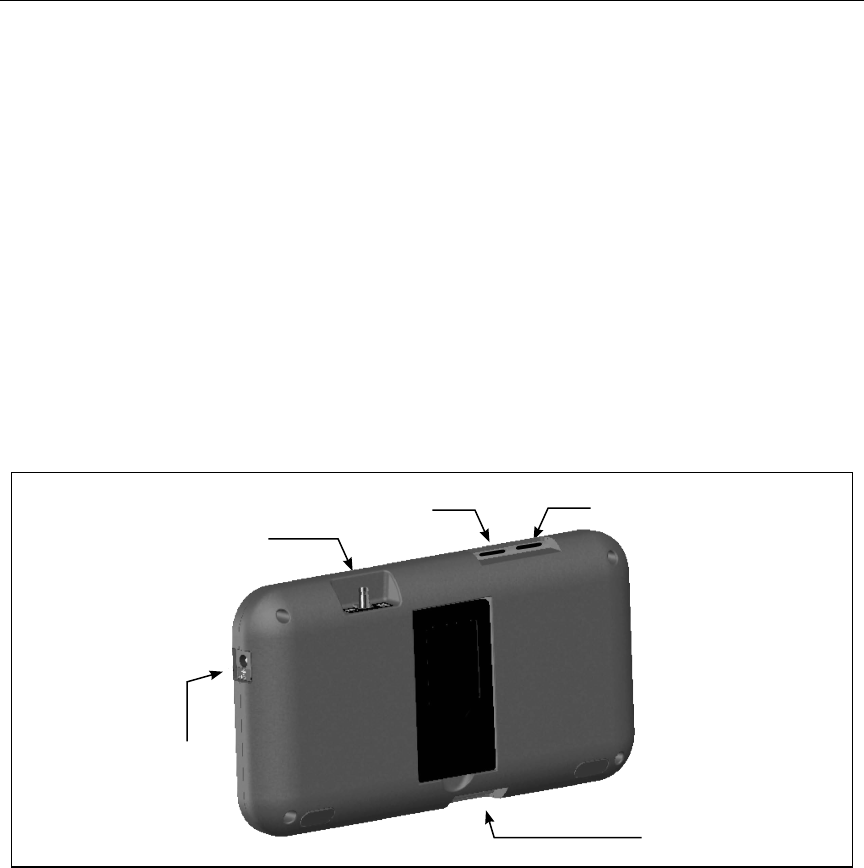
Programmer Controls and Connections
Figure 1:
microSD™ slot
(for technical support use)
Power button
Volume control
Telemetry wand connector port
External power supply port
Controls and external connections

8
QTECH™ PROGRAMMER: OPERATION
Charging the Programmer
The programmer is primarily intended to be operated while connected to the AC-powered external
power supply, but may also be operated on battery power provided that the internal battery is
adequately charged. The programmer is recharged whenever it is connected to the AC-powered
external power supply. When not in use, it is recommended that the programmer remain connected
to the external power supply in order to maintain an adequate battery charge.
Note: Current session data may be lost if a 45 minute period of inactivity
occurs during an active telemetry session and the programmer is not
connected to AC power.
Typical charge time for a fully discharged battery is 5 hours. However, more time may be required if
the programmer is in use while being recharged.
The Battery Status indicator located on the upper right corner of the screen displays the status of
the main battery power when the unit is in use:
• All four bars are illuminated (green) - The battery is 100% charged
• Three bars are illuminated (green) - The battery is 75% charged
• Two bars are illuminated (yellow) - The battery is 50% charged
• One bar is illuminated (red) - The battery is 25% charged
The programmer displays one of the following alert screens as battery power gets progressively lower.
• Programmer Battery Low
• Programmer Battery Critical
• Out Of Power
To charge the programmer:
1. Connect the external power supply cable to the programmer (Figure 2).
2. Plug the external power supply cord into an AC power outlet.
9
QTECH™ PROGRAMMER: OPERATION
Figure 2: Connecting the external power supply
Using the Q-TECH Programmer
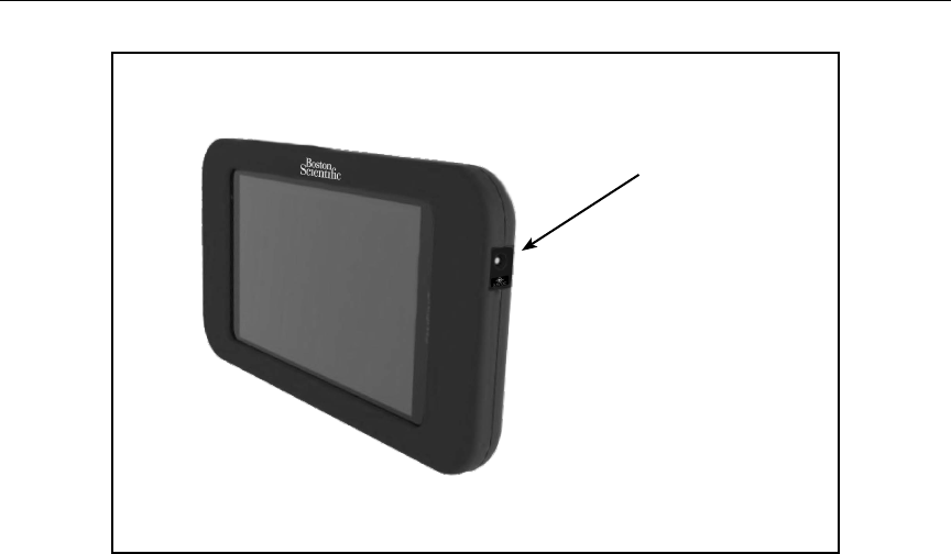
Turning the Programmer On
The programmer power button is located in the recess above and behind the left corner of the
screen. Press and hold the button until the display screen is active (Figure 3).
External power supply port
10
QTECH™ PROGRAMMER: OPERATION
Figure 3: Turning the programmer On/O and changing the volume level
Note: If the programmer cannot be turned on while it is connected to AC power
via the external power supply, rst unplug the external power supply
cord from the programmer. Press and hold the programmer power
button until the display screen is active (Figure 3). AC power via the
external power supply can then be reconnected.
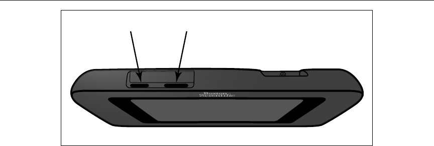
Changing the Programmer Volume Level
The volume level of programmer-generated sounds may be temporarily adjusted using the volume
control (Figure 3). This level is automatically reset when the programmer is restarted.
Placing the Programmer in Suspend Mode
The programmer has a Suspend Mode which is activated automatically to conserve power. The
display will be blank when this mode is in eect.
The programmer enters Suspend Mode whenever:
• The power button (Figure 3) is momentarily pressed and released
• The programmer is not connected to the external power supply, it is not in active
communication with an SQ-RX pulse generator, and no user activity has occurred for 15
minutes
Momentarily pressing the power button will resume normal operation.
Power On/O Volume Control
11
QTECH™ PROGRAMMER: OPERATION
Turning the Programmer O
There are two ways to turn the programmer o:
1. Press and hold the power button (Figure 2) until the System shutdown menu
appears. Select Power o from the popup and conrm by pressing OK.
2. From the on-screen Main Menu, press the Power O button and select OK at the
conrmation prompt.
Using the Programmer Touch Screen
The programmer is equipped with an LCD touch screen. The screen can be adjusted to the desired
viewing angle by using the kick-stand located on the back of the programmer. All interaction with
the programmer is conducted using the ngers to touch the appropriate areas on the screen.
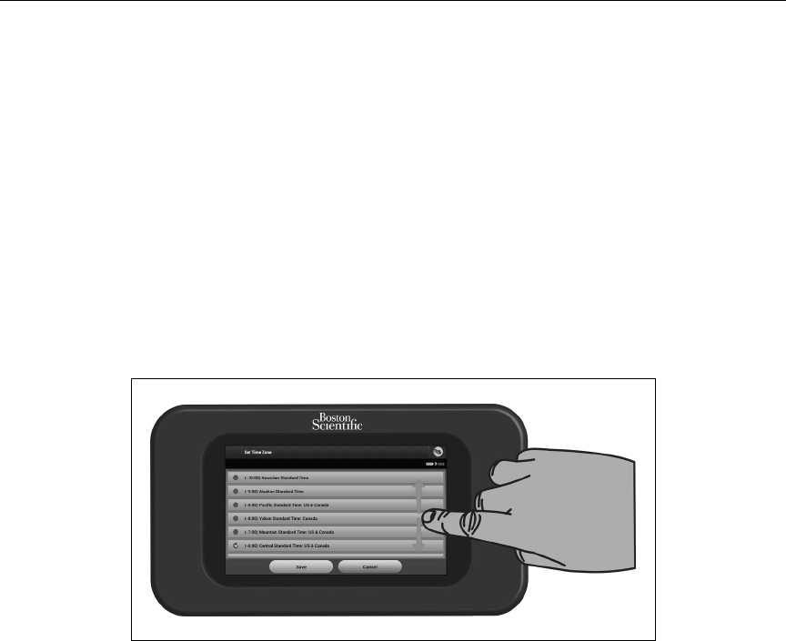
Scroll on-screen lists by sliding a nger up and down the list (Figure 4). An on-screen keyboard is
presented whenever text entry is required.
Figure 4: Scrolling on-screen lists
12
QTECH™ PROGRAMMER: OPERATION
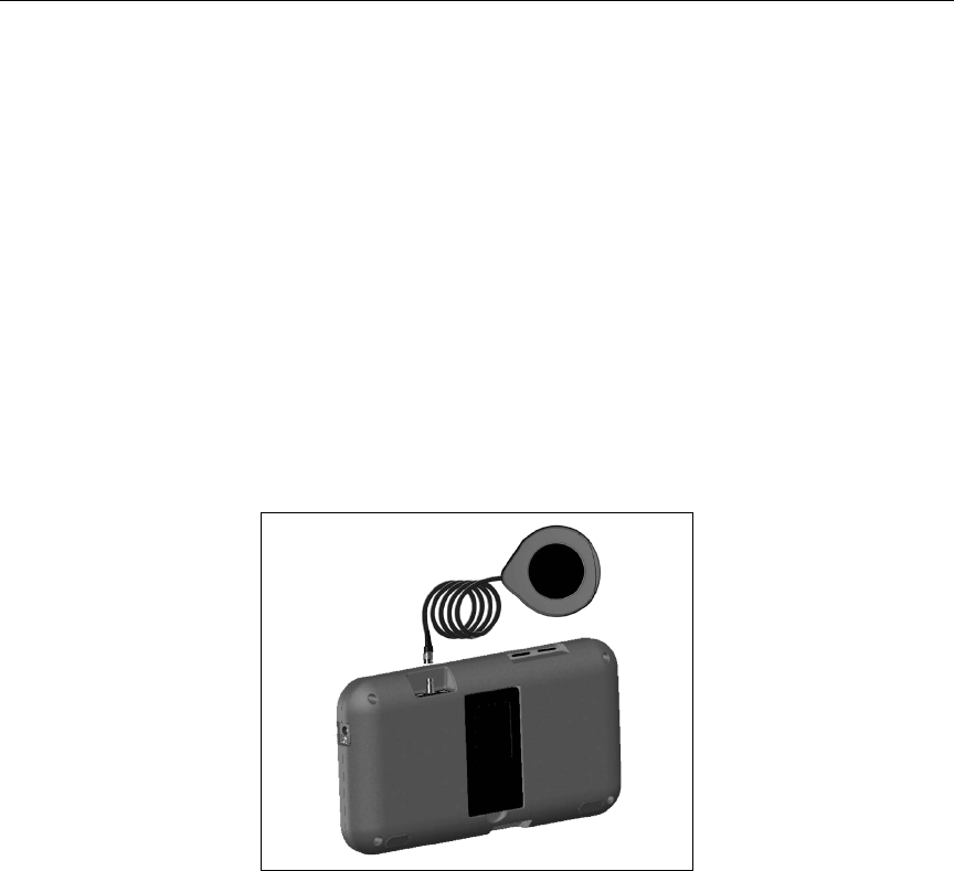
Using the Wand
Model 3203 wand (“the wand”) makes it possible for this programmer to communicate with the
SQ-RX device.
Note: The wand is a non-sterile device. DO NOT STERILIZE the wand or the
programmer. The wand must be contained in a sterile barrier before use
in the sterile eld.
To connect the wand to the programmer, slide the wand cable connector over the communication
connector port located on the rear edge of the programmer (Figure 5).
To disconnect the wand, grasp the wand cable connector and gently pull it straight o the
communication connector port.
Note: Do not pull or yank on the cable to disconnect the wand from the
programmer. Such action could cause hidden damage to the cable. A
damaged cable might reduce wireless communication capabilities and
require a replacement wand.
Figure 5: Connecting the wand
To obtain optimal telemetry, the wand should be placed directly over the implanted SQ-RX device.
Although the programmer may receive S-ECG telemetry at greater distances, programming should
be performed with the wand placed over the SQ-RX device.

13
QTECH™ PROGRAMMER: OPERATION
When telemetry loss occurs, the display screen will turn yellow and a message will appear with the
text “Communication Loss” to alert the user. Reposition the wand to establish communication. The
programmer will display a screen informing the user if the SQ-RX device is found and programming
can continue.
Note: If communication cannot be reestablished, the session should be ended
and restarted by scanning for the SQ-RX device.
Navigation
The programmer’s graphic user interface (GUI) facilitates management and control of the S-ICD
System. The Navigation Bar and on-screen icons at the top of the screen allow the user to navigate
programming software screens. In addition, a continuous subcutaneous electrocardiogram (S-ECG)
is displayed along the bottom of the screen during Online (active) communication with the SQ-RX
device.
Screen Header
When the programmer is Oine (inactive communication), the screen header displays the Battery
Status Indicator.
When viewing Oine Stored Sessions, the screen header displays:
• Patient name
• Therapy On/O
• Battery status indicator
When the programmer is online (active communication), the screen header displays:
• Therapy On/O
• Patient name
• Patient heart rate
• Programmer Battery and Telemetry status indicator
• Screen title
• Rescue shock icon

14
QTECH™ PROGRAMMER: OPERATION
Navigation Bar
The Navigation Bar is the primary method for navigating the Online programmer screens. The bar
is located along the top edge of the programmer screen and chosen screens appear with their
selection icon highlighted.
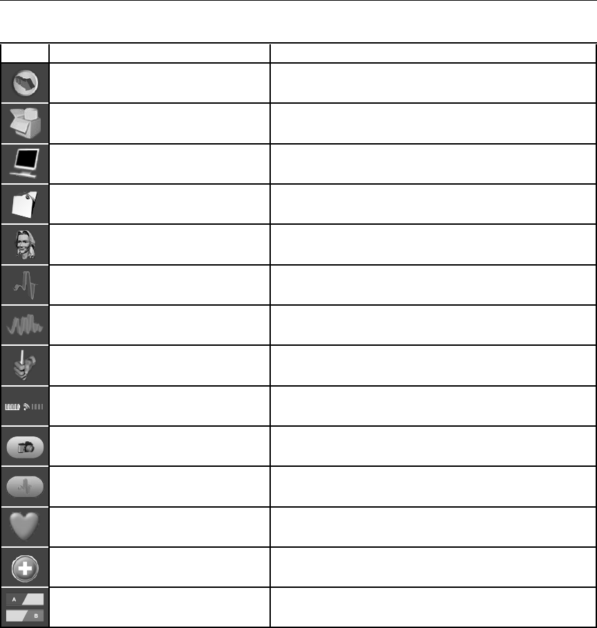
Table 1 displays a list of the programmer icons and their corresponding descriptions.
Restarting the Programmer
The programmer’s operating system is self-monitoring and is generally able to sense many system
error conditions and automatically initiate a restart sequence in response. Follow the on-screen
instructions to complete the programmer-initiated restart sequence.
The programmer may need to be manually restarted if:
• You cannot exit a screen
• The operating system stops responding
A manual restart is accomplished by pressing and holding the power button until the system
shutdown menu appears on the screen. Select Restart from the popup and conrm
by pressing OK.
If the programmer does not respond to a restart process, contact your Cameron Health/Boston
Scientic representative or the customer service department for assistance.
15
QTECH™ PROGRAMMER: OPERATION
Table 1: Icon descriptions
Icon Description User Application
Main Menu Icon Allows user to return to the main menu.
Automatic Setup Icon Allows user to access the automatic setup menu.
Device Settings Icon Allows user to access the SQ-RX device settings screen.
Device Status Icon (open folder and closed folder) Allows user to access the SQ-RX device status screen. User can view number of shocks
delivered since the last update as well as the SQ-RX device battery life.
Patient View Icon Allows user to access the patient chart screen.
Captured and Stored Episodes S-ECG Icon Allows user to access captured S-ECG and stored episode screens.
Induction Test Icon Allows user to access induction screen.
Manual Shock Icon Allows user to access the manual shock screen.
Battery & Telemetry Meter Left side of the meter allows user to view the programmer’s battery status.
The right side of the meter allows viewing of telemetry signal.
Capture S-ECG Allows user to capture a live S-ECG.
S-ECG Display Settings Allows user to modify the zoom and sweep speed on the live S-ECG.
Heart Rate Icon Allows user to view current heart rate.
Rescue Shock Icon Allows user to administer a rescue shock
Option Selection Slider Switch Allows user to select one of two options, e.g. A or B
16
QTECH™ PROGRAMMER: OPERATION
Conguring the Q-TECH Programmer
Conguring Programmer Settings
The programmer should be congured before communication with an SQ-RX device is attempted.
This includes setting the date and time format, time zone, language and printer. Once these settings
are congured during the initial setup process they become the default parameters and will not
normally need to be changed with each session.
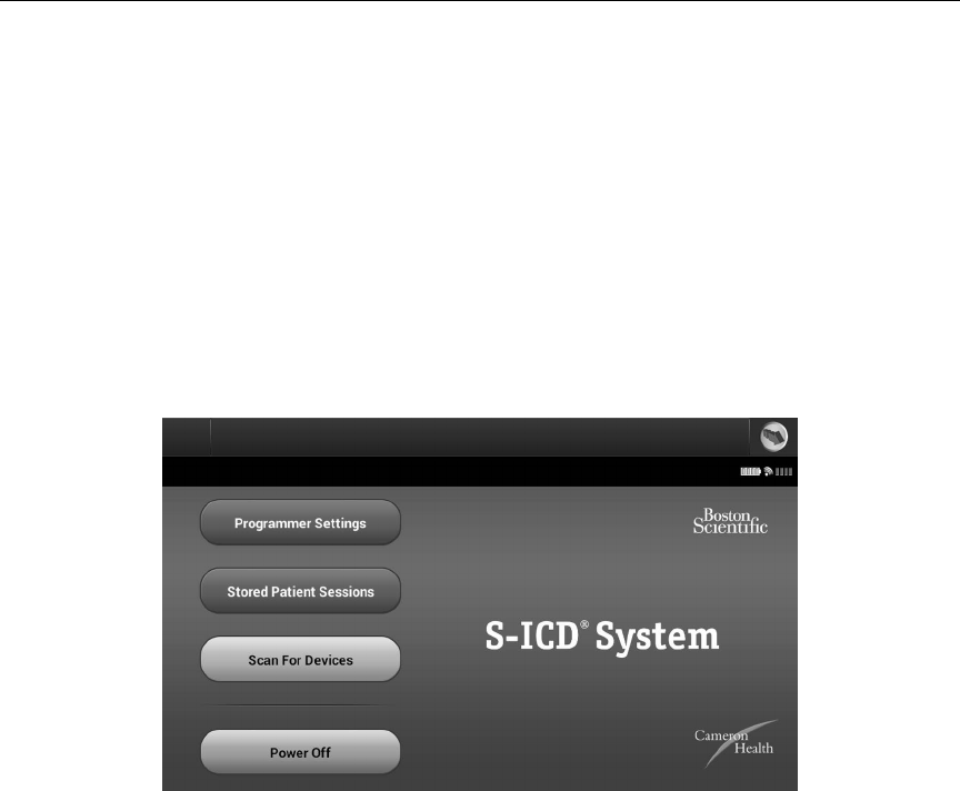
To congure the programmer settings:
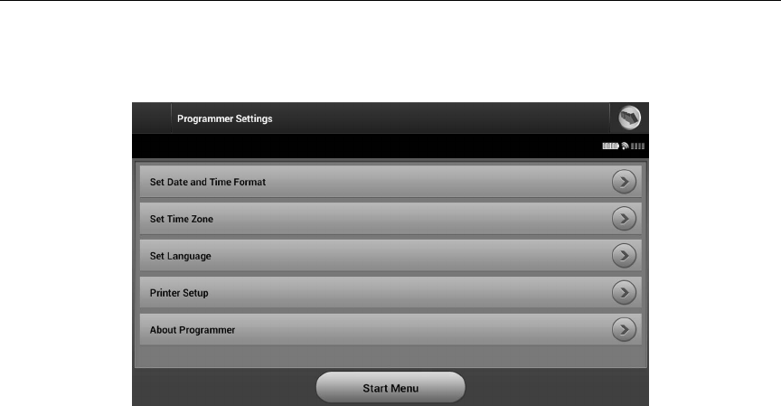
1. Select the Programmer Settings button on the Startup screen (Figure 6) to
display the Programmer Settings screen (Figure 7).
Figure 6: Startup screen
17
QTECH™ PROGRAMMER: OPERATION
Figure 7: Programmer Settings screen
2. Select the corresponding line to access each setting. The settings that can be
congured include:
• Date and time format
• Time zone
• Language
• Printer
18
QTECH™ PROGRAMMER: OPERATION
Date and Time Format
To set the date and time format:
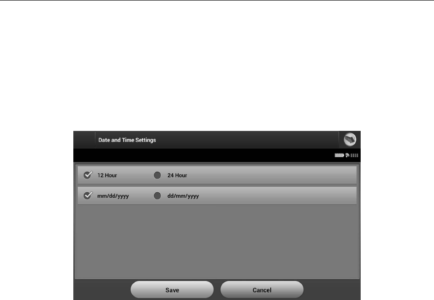
1. Select Set Date and Time Format on the Programmer Settings screen (Figure 7).
The Date and Time Settings screen appears (Figure 8).
2. Select the desired date format.
3. Select the Save button to save the changes and return to the Programmer Settings screen,
or select Cancel to return to the Programmer Settings screen without saving the changes.
Figure 8: Date and Time Settings screen
Time Zone
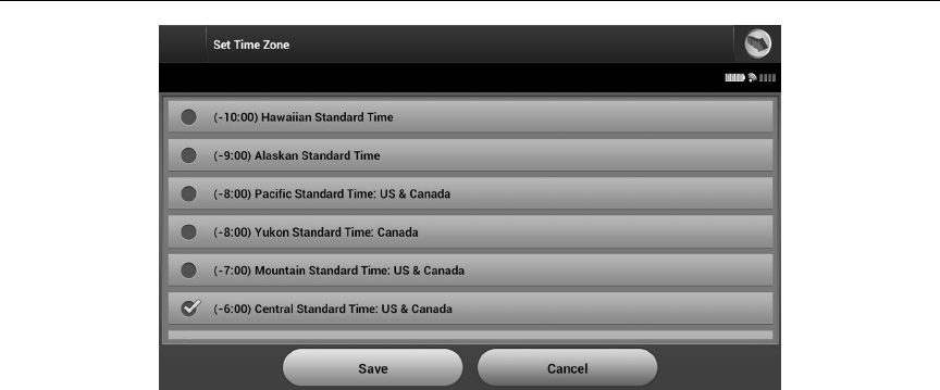
To set the time zone in which the programmer will be used:
1. Select Set Time Zone on the Programmer Settings screen. The time zone selec-
tion screen appears (Figure 9).
2. Select the country/time zone button for the zone in which the programmer will
be used. A checkmark will appear in the selected button. The SQ-RX device line
frequency of 50 Hz or 60 Hz is automatically programmed based on the country/time
zone selected.
19
QTECH™ PROGRAMMER: OPERATION
Figure 9: Time Zone selection screen (scrollable list)
3. Select the Save button to save the changes and return to the Programmer Settings
screen, or select Cancel to return to the Programmer Settings screen without saving
the changes.
Language Preference
To set the language preference:
1. Select Set Language on the Programmer Settings screen. The Language Settings
screen appears.
2. Select the Save button to save the changes or select Cancel to return to the
Programmer Settings screen without saving the changes. If the language is changed
the programmer will automatically restart and return to the Startup screen.
Printer Selection
The programmer communicates with the printer wirelessly via Bluetooth® technology. Only
Cameron Health/Boston Scientic-approved printers can be used with the programmer. To select
the printer to be used with the programmer:
1. Ensure the printer is on and, as applicable, the wireless function is enabled or the
wireless adapter is in the printer’s USB port.
20
QTECH™ PROGRAMMER: OPERATION
2. Select Printer Setup on the Programmer Settings screen. A previously congured
printer becomes the default printer and will be displayed at this time. If a default
printer has not already been selected and congured, the programmer will scan the
area to locate wireless printers. A Scan Progress Bar will appear informing the user
that the programmer is currently scanning for printers.
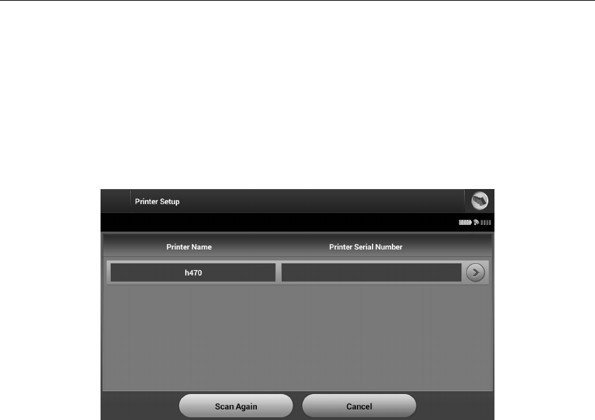
3. Select the printer of choice (Figure 10). If no printers are found, a window will appear
stating that there are no printers. Select the Scan Again button or the Cancel button
to return to the Programmer Settings screen. If a printer was selected during another
session, the Printer Setup screen is displayed.
Figure 10: Printer Selection screen
4. Once the scan is complete, the Printer Selection screen appears (Figure 10).
Note: Refer to “Troubleshooting” section for printer problems.
5. Select the desired printer name and enter the name using the on-screen keyboard
(up to 15 characters). A unique printer identier should appear with the printer
selection (Figure 11).
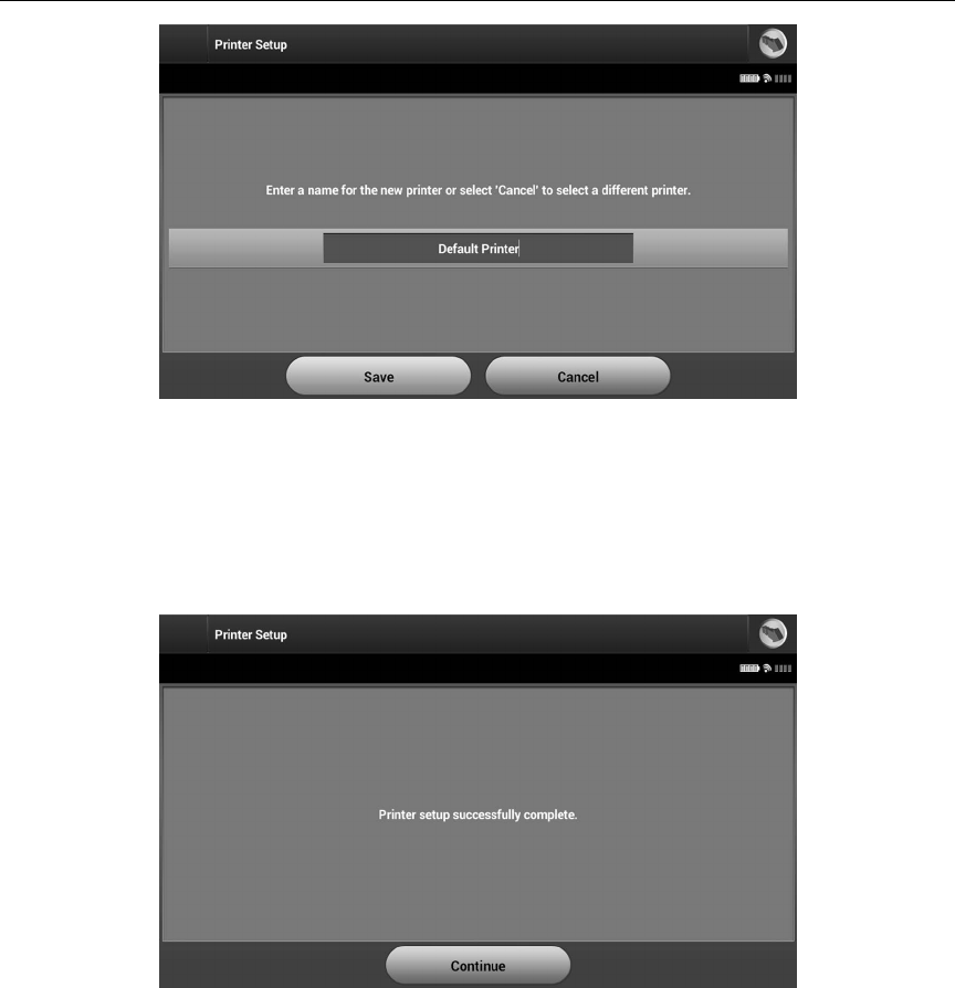
21
QTECH™ PROGRAMMER: OPERATION
Figure 11: Use the on-screen keyboard to enter a name for the selected printer
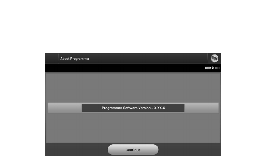
6. Select the Save button to save the changes and return to the Programmer Settings
screen, or select Cancel to return to the Programmer Settings screen without saving
the changes. A conrmation screen will appear when the printer setup is completed
(Figure 12).
Figure 12: Printer Setup conrmation screen
22
QTECH™ PROGRAMMER: OPERATION
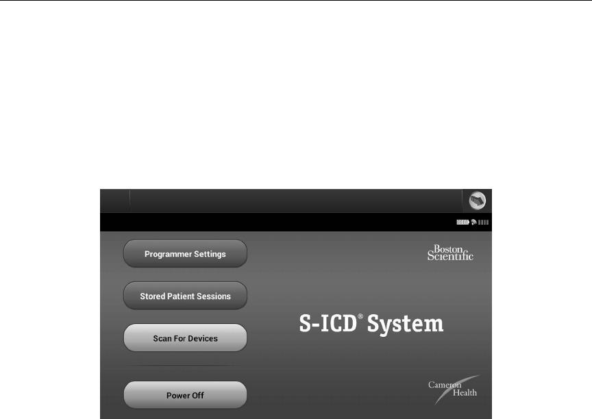
Programmer Software Version
To view the programmer’s software version:
1. Select About Programmer on the Programmer Settings screen. The Programmer
Software Version information screen appears (Figure 13).
Figure 13: Programmer Software Version information screen
2. This screen displays the current version of the programmer software. Select the
Continue button to return to the Programmer Settings screen.
Note: The patient printed report contains the programmer software version.
Modes of Operation for the Q-TECH Programmer
Online Behavior
The programmer’s interface varies according to whether the programmer is Online (actively
communicating) or Oine (not communicating) with a selected SQ-RX device.
An Online session begins when the programmer establishes a telemetry link with a specic SQ-RX
device. A yellow alert screen is displayed if the telemetry signal is lost between the programmer and
the SQ-RX device for more than ve seconds during active communication. This may occur if the

23
QTECH™ PROGRAMMER: OPERATION
wand is moved out of the telemetry communications range or if noise or interfering objects inhibit
communication. Programming commands, including Rescue Shocks, will not be available until
telemetry is reestablished.
Telemetry reconnection may occur automatically within one minute when the SQ-RX device and
wand are within telemetry range.
Note: Whenever the programmer is in active communication with an SQ-RX
device, charging of the pulse generator in preparation for delivering a
shock (whether commanded or in response to a detected arrhythmia) is
indicated by an audible notication. The notication continues until the
shock is delivered or aborted.
Oine Behavior
When the programmer is not actively communicating with an SQ-RX device it is Oine. During
Oine sessions, programmer settings can be accessed, and stored patient sessions can be viewed
and/or printed.
Stored Patient Sessions
During a patient follow-up visit, the programmer will retrieve data from the SQ-RX device’s
memory. The programmer can store up to 50 patient sessions. When the 51st session occurs,
the programmer will automatically replace the oldest stored session with the new data. A stored
session includes the following information:
• Captured S-ECG Reports
• Episode History (including any downloaded episodes)
• Patient Data
• Programmed Device Settings
To view stored patient sessions:
1. From the Startup screen, select Stored Patient Sessions.
2. Select the desired patient session.

24
QTECH™ PROGRAMMER: OPERATION
Modes of Operation for the SQ-RX Device
The SQ-RX device has three modes of operation:
• Shelf
• Therapy On
• Therapy O
Shelf Mode
The Shelf mode is a low power consumption state intended for storage only. When communication
is initiated between the SQ-RX device and the programmer, a full-energy capacitor reformation is
automatically performed and the SQ-RX device is prepared for set-up. Once the SQ-RX device is
taken out of Shelf mode, it cannot be reprogrammed back into Shelf mode.
Therapy On Mode
The Therapy On mode is the primary operating mode of the SQ-RX device, allowing automatic
detection of, and response to, ventricular tachyarrhythmias.
Note: The SQ-RX device must be programmed out of Shelf mode before being
programmed to Therapy On.
Therapy O Mode
The Therapy O mode disables automatic therapy delivery and enables manual control of shock
delivery. Programmable parameters may be viewed and adjusted via the programmer. Also, the
subcutaneous electrogram (S-ECG) may be displayed or printed.
The SQ-RX device automatically defaults to Therapy O mode when the SQ-RX device is taken out
of Shelf mode.
Note: Manual and rescue shock therapy are available once the initial Setup
process is complete.
25
QTECH™ PROGRAMMER: OPERATION
Connecting and Disconnecting from the SQ-RX Device
This section provides the information necessary for selecting, connecting to, and disconnecting from
the SQ-RX device.
Scanning For SQ-RX Devices
1. Select the Scan For Devices button on the Startup Screen (Figure 14). The Device
List screen appears after the Scan Progress Bar displayed during the scanning
process. Select the Cancel button at any time to end the scanning process.
Figure 14: Startup screen
26
QTECH™ PROGRAMMER: OPERATION
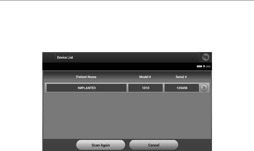
2. When the scanning process is complete, a list of all SQ-RX devices detected (up to 16)
will be displayed on the Device List (Figure 15). The SQ-RX devices that are in Shelf
mode will be displayed as “Not Implanted.” Any SQ-RX devices that were previously
taken out of Shelf mode are displayed either as “Implanted” or with the stored patient
name.
Figure 15: Device List screen (scrollable list)
3. If the desired SQ-RX device is not listed, select the Scan Again button to re-initiate the
scanning process. Select the Cancel button to return to the Startup screen.
Note: Refer to the Inability to Communicate with the SQ-RX Device section for
further assistance.
27
QTECH™ PROGRAMMER: OPERATION
Connecting to the SQ-RX Device
From the Device List screen, select the desired SQ-RX device to initiate the communication session.
Note: Regardless of how many SQ-RX devices are located by a scan, the user
must select an SQ-RX device from the list to begin active communication.
Connecting to an SQ-RX Device in Shelf Mode:
1. When the SQ-RX device selection is made, the programmer connects to the
selected SQ-RX device. A window will appear indicating connection is in process.
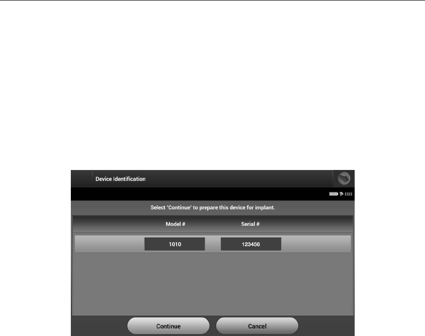
2. Once communication is established with the SQ-RX device, the Device Identication
screen appears (Figure 16).
Figure 16: Device Identication screen
Note: The Device Identication screen is visible only while connecting to an SQ-RX device in Shelf
mode.
3. The SQ-RX device model and serial numbers are automatically acquired and
displayed during the initial scanning process. Select Continue to remove the SQ-RX
device from Shelf mode and prepare for implantation, or select Cancel to return to
the Device List screen.

28
QTECH™ PROGRAMMER: OPERATION
Ending a Patient Session
To end an Online patient session and return the programmer to its Oine operation mode:
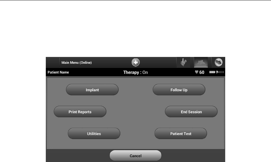
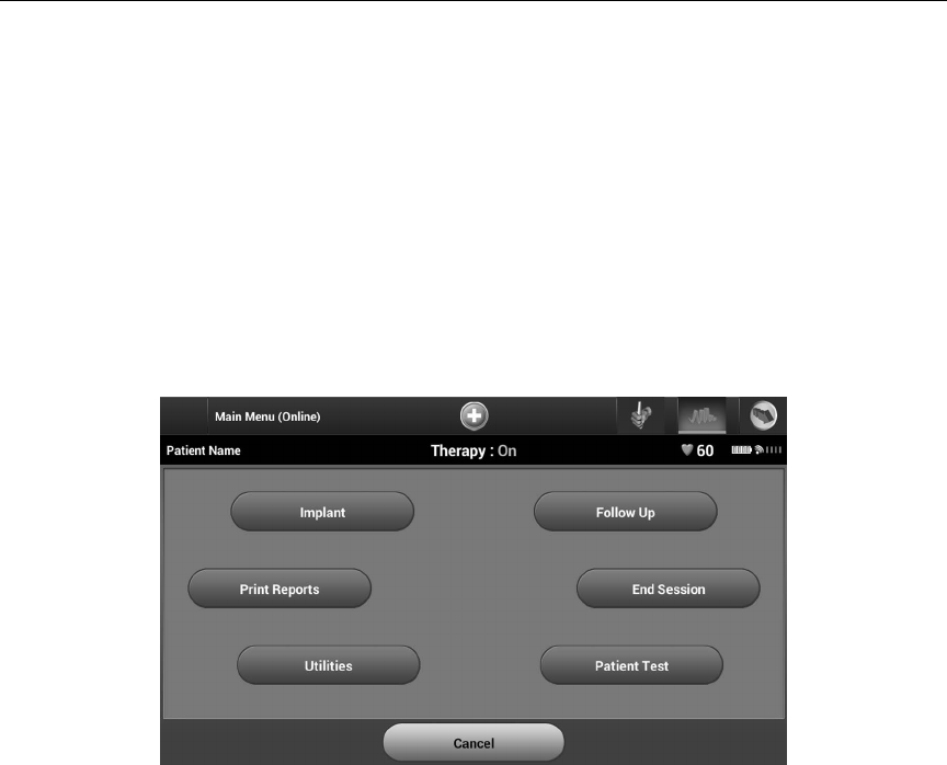
1. Select the Main Menu icon on the Navigation Bar. The Main Menu screen appears.
2. Select the End Session button (Figure 17).
Figure 17: Main Menu screen
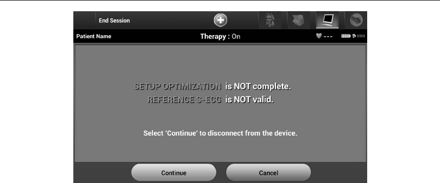
3. A warning message will be displayed to the user if any of the following conditions
exists:
• Automatic Therapy is programmed to O
• Reference S-ECG has not been acquired
• Automatic Setup or Optimization has not been completed. This message is
typically displayed following the implant procedure as Setup Optimization was not
performed (Figure 18).
4. Select the Continue button to end the patient session and return to the Startup Menu
screen, or select Cancel to remain online and return to the Main Menu screen.
29
QTECH™ PROGRAMMER: OPERATION
Figure 18: Session incomplete message
Note: Once the Continue button is selected, the session is stored and
communication is terminated.
Note: A telemetry session must be terminated using the End Session process
as described in steps 1 through 4 above in order for data obtained
during that session to be saved. If the programmer is powered o
during a session, either automatically or manually, session data will not
be saved.
Note: In order to conrm that Automatic Therapy is programmed On upon
disconnection, always use the End Session process and review all
displayed warning messages.
30
QTECH™ PROGRAMMER: OPERATION
Programming the SQ-RX Device at Implant
This section provides the information necessary for programming the SQ-RX device during an implant
setting.
Entering Electrode Information
The programmer maintains information on the implanted electrode. To record this information for a
patient’s new or replacement electrode:
1. Select the Main Menu icon.
2. Select the Implant button.
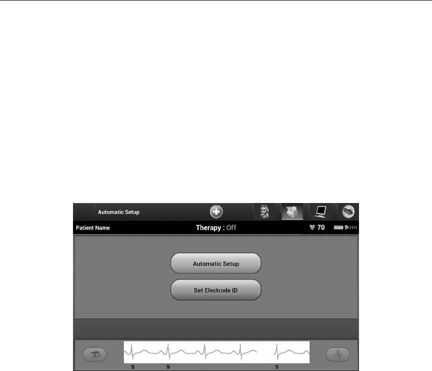
3. Select the Automatic Setup icon in the Navigation Bar. The Automatic Setup screen
appears (Figure 19).
4. Select Set Electrode ID button.
Figure 19: Select the Set Electrode ID button to enter electrode information
Note: ECG and heart rate information is not present on the Automatic Setup
and Electrode ID setup screens until the electrode has been connected to
the SQ-RX device.
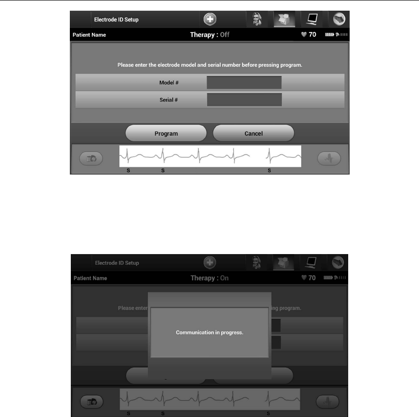
5. Enter the electrode model and serial number (Figure 20).
31
QTECH™ PROGRAMMER: OPERATION
Figure 20: Entering electrode information
6. Select the Program button to save the information. A conrmation screen will appear
during communication with the SQ-RX device (Figure 21). Select Cancel to cancel
information storage and return to the Automatic Setup screen.
Figure 21: Conrmation screen showing communication in progress
32
QTECH™ PROGRAMMER: OPERATION
Creating the Patient Chart
This chart contains reference information for the patient. To set up the patient chart:
1. Select the Main Menu icon on the Navigation Bar.
2. Select the Implant button (Figure 22).
Figure 22: Select the Implant button to create a patient chart
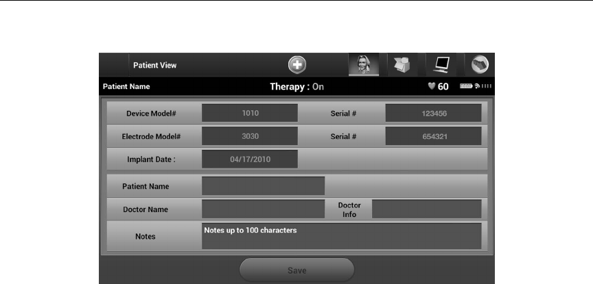
3. Select the Patient View icon to access the Patient View screen.
4. The SQ-RX device model and serial numbers appear on the rst line of the chart.
The electrode model and serial numbers appear on the second line of the chart. The
implant date appears on the third line of the chart (Figure 23). Using the on-screen
keyboard, enter the following patient information:
• Patient Name: up to 25 characters
• Doctor Name: up to 25 characters
• Doctor Info: up to 25 characters
• Notes: up to 100 characters
33
QTECH™ PROGRAMMER: OPERATION
Figure 23: Patient Chart screen
Note: The Notes eld will automatically wrap the text with the presence of a
space between any characters within the rst line.
5. Select the Save button to update the SQ-RX device with the patient information.
Note: Failure to save the new patient information will result in loss of the
entered data.
34
QTECH™ PROGRAMMER: OPERATION
Automatic Setup
Before the SQ-RX device can be activated, it must go through an initial Automatic Setup Process at
the time of the implant.
The Automatic Setup Process is initiated as follows:
1. Select the Main Menu icon.
2. Select the Implant button.
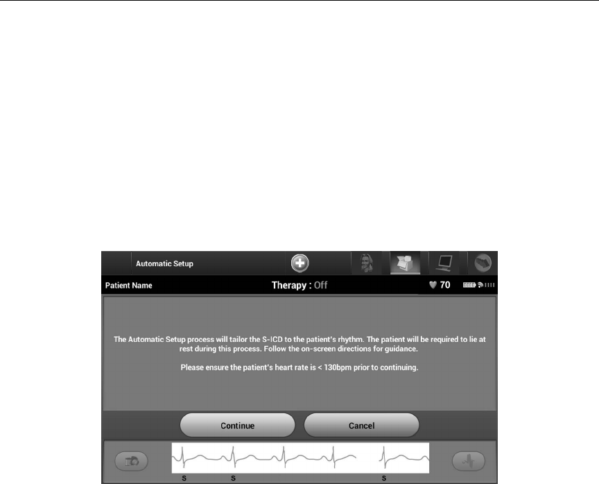
3. Select the Automatic Setup icon on the navigation bar. The Automatic Setup screen
appears (Figure 24).
4. Select Continue if the patient’s heart rate is less than 130 bpm. For rates greater than
130 bpm, select the Cancel button and refer to the instructions for Manual Setup.
Figure 24: Automatic Setup screen
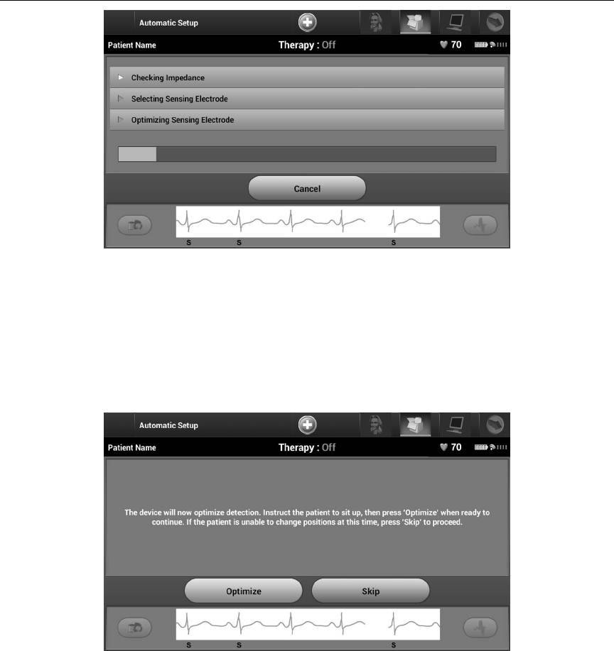
5. Once started the Automatic Setup will:
• Perform the shock electrode integrity check to measure electrode impedance
(Figure 25). Normal sub-threshold impedance range is < 400 Ohms.
• Select the best sensing conguration. The sense electrode conguration appears on
the printed report and can be viewed via the Manual Setup process.
• Select the appropriate gain selection. The selected sense gain appears on the
Printed Report and can be viewed via the Manual Setup process.
35
QTECH™ PROGRAMMER: OPERATION
Figure 25: Measuring electrode impedance
The progress of the Automatic Setup process is shown in the status bar. When each
function is complete, the arrow next to the function moves to a down position.
6. The Automatic Setup Sensing Optimization screen will be displayed. The programmer
will display a message requesting that the patient sit up; however, this process can be
omitted during the implantation procedure by selecting the Skip button (Figure 26).
Figure 26: Automatic Setup screen
36
QTECH™ PROGRAMMER: OPERATION
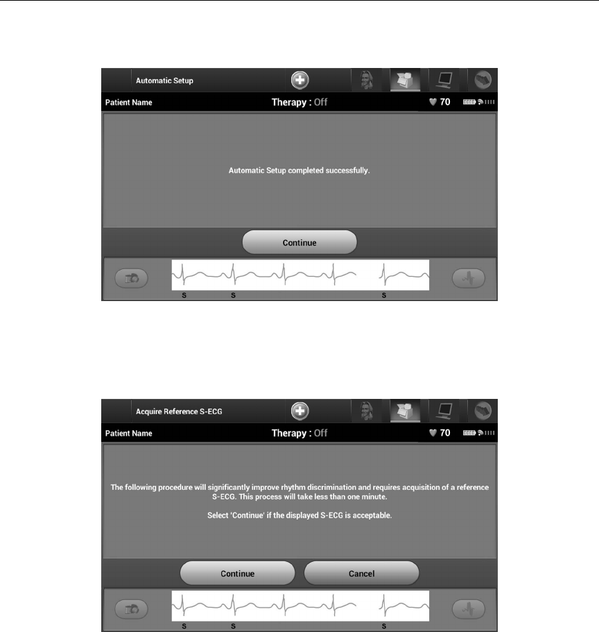
7. Select the Continue button to nish the Automatic Setup process. A conrmation
screen will appear when Automatic Setup is complete (Figure 27).
Figure 27: Conrmation of successful Automatic Setup
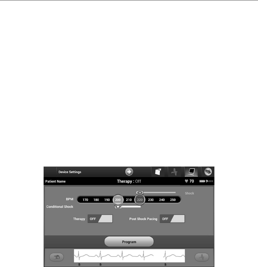
8. Following the optional optimization process, the Acquire Reference S-ECG screen is
displayed (Figure 28). Select the Continue button to acquire a reference S-ECG.
Figure 28: Acquire Reference S-ECG screen
37
QTECH™ PROGRAMMER: OPERATION
9. Once the Reference S-ECG acquisition process begins, a status screen appears. The
process may take up to one minute, during which the patient should remain still.
During this process, a template of the patient’s baseline QRS complex is stored in the
SQ-RX device. Select Cancel at any time to end Reference S-ECG acquisition. When
acquisition is complete, select the Continue button.
Programming Therapy Parameters
Once Automatic Setup has been completed, the SQ-RX device therapy parameters may be selected.
Note: The IDE Study demonstrated a signicant reduction in inappropriate
therapy with the activation of the Conditional Shock Zone prior to
hospital discharge (see SQ‐RXPulse Generator User’s Manual, Section:
S‐ICD System Clinical Investigation).
To set the therapy parameters:
1. Select the Main Menu icon on the Navigation Bar.
2. Select the Implant button.
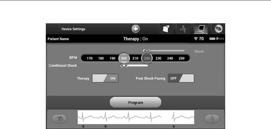
3. Select the Device Settings icon on the Navigation Bar to display the Device Settings
screen (Figure 29).
Figure 29: Device Settings screen
38
QTECH™ PROGRAMMER: OPERATION
4. Select the On/O Therapy switch to set the desired therapy mode (Figure 30).
Figure 30: Setting the On/O Therapy switch
5. Select and drag the Conditional Shock Zone (yellow) and Shock Zone (red) slider bars
to set the desired zone conguration.
• The Shock Zone is programmable between 170 and 250 bpm in steps of 10 bpm.
• The Conditional Shock Zone is programmable between 170 and 240 bpm in steps
of 10 bpm. Enhanced detection criteria are automatically enabled when the Condi-
tional Shock Zone is programmed.
• When programming both the Shock Zone and Conditional Shock Zone, maintain
at least a 10 bpm dierence between the two zones. If the Conditional Shock Zone
slider (yellow) is dragged over the Shock Zone slider (red), the two sliders will merge
to create a single Shock Zone.
6. If post-shock pacing is desired, slide the Post Shock Pacing switch to the On position.
(Post-shock bradycardia pacing occurs at a non-programmable rate of 50 bpm for up
to 30 seconds. Pacing is inhibited if the intrinsic rate is greater than 50 bpm.)
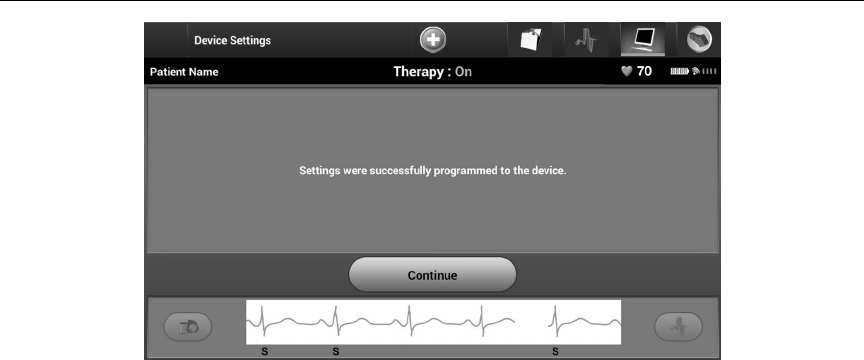
7. Select the Program button to apply the changes and program the SQ-RX device.
A screen will appear to conrm that the SQ-RX device settings were programmed
(Figure 31). If the SQ-RX device does not accept the SQ-RX device programming, a
Program Device alert screen will appear. Select the Try Again button to return to the
Device Settings screen.
39
QTECH™ PROGRAMMER: OPERATION
Figure 31: Conrmation of programming
8. Once programming is conrmed, select the Continue button to proceed to the next
operation.
Note: If any of the SQ-RX device settings are changed from the Device Settings
screen and not subsequently programmed, the Pending Program
Changes screen will appear. You may select Cancel to return to the
Device Settings screen or select Continue to cancel all SQ-RX device
setting changes.
40
QTECH™ PROGRAMMER: OPERATION
Debrillation Testing
Once the SQ-RX device is implanted and Automatic Therapy is programmed On, debrillation
testing may be conducted.
Note: Debrillation testing is recommended at implant to conrm the ability of
the S-ICD System to sense and convert VF.
Note: Episode data associated with rescue shocks, manual shocks, and
induction testing is not stored in the SQ-RX device.
To induce VF and test the S-ICD System:
1. Select the Main Menu icon on the Navigation Bar to access the Main Menu.
2. Select the Patient Test button to setup the induction test (Figure 32).
Figure 32: Select the Patient Test Button to access the Induction Test screen.
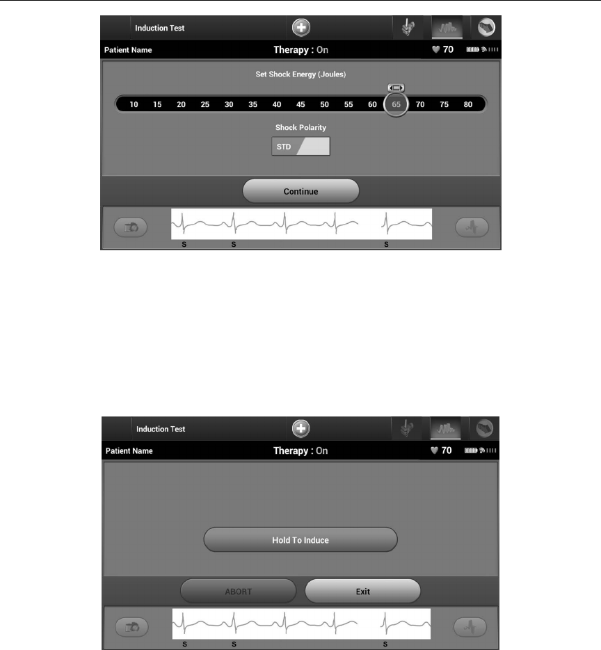
3. Select either standard (STD) or reverse (REV) polarity (Figure 33).
4. Select and drag the red marker to set the desired shock energy for the rst delivered
shock. The shock energy may be programmed from 10 to 80 J. A 15 J safety margin is
recommended for debrillation testing.
41
QTECH™ PROGRAMMER: OPERATION
Figure 33: Setting the desired rst shock energy for debrillation testing
5. Select the Continue button to display the next Induction Test screen.
Note: Ensure that noise markers (“N”) are not present on the S-ECG prior to
induction. The presence of noise markers may delay detection and
therapy delivery.
6. Select and hold the Hold To Induce button for the desired duration (Figure 34).
Figure 34: Induction Test screen

42
QTECH™ PROGRAMMER: OPERATION
The following functions occur during the test:
• The S-ICD System induces ventricular brillation using 200 mA alternating current
(AC) at 50 Hz. Induction continues until the Hold To Induce button is released (up to
a maximum of 10 seconds per attempt).
Note: If necessary, the induction can be terminated by disconnecting the
wand from the programmer.
• Arrhythmia detection and the Live S-ECG are suspended during AC induction. Once
the Induction button is released, the programmer displays the patient’s rhythm.
• Upon detection and conrmation of an induced arrhythmia, the S-ICD System
automatically delivers a shock at the programmed energy output and polarity.
Note: Whenever the programmer is in active communication with an SQ-RX
device, charging of the pulse generator in preparation for delivering a
shock (whether commanded or in response to a detected arrhythmia)
is indicated by an audible notication. The notication continues until
the shock is delivered or aborted.
• If the shock fails to convert the arrhythmia, re-detection occurs and subsequent
shocks are delivered at the SQ-RX device’s maximum energy output (80 J).
Note: Following the release of the Hold To Induce button, evaluate the
sensing markers during the induced rhythm. The S-ICD System uses
a lengthened rhythm detection period. Consistent tachy “T” markers
indicate that tachyarrhythmia detection is occurring, and that
capacitor charging is imminent. If a high degree of amplitude variation
is noted during the arrhythmia, a slight delay may be expected prior to
capacitor charging or shock delivery.
Note: The SQ-RX device can deliver a maximum of ve shocks per episode. At
any time, an 80 J rescue shock can be delivered by pressing the Rescue
Shock icon.
7. At any time prior to therapy delivery, the programmed energy may be aborted by
selecting the red Abort button.
8. Select the Exit button to exit the induction process and return to the Main Menu
screen.

43
QTECH™ PROGRAMMER: OPERATION
Performing an SQ-RX Follow-up
Sensing Conguration and Automatic Setup
It is not necessary to perform Automatic Setup at each follow-up. If Automatic Setup is performed,
resulting in a vector change, sensing should be reevaluated. After the setup process is complete,
evaluate the streaming S-ECG during a pectoral exercise. Sensing performance during high rate
exercises can also be performed. Acceptable sensing will yield “S” markers synchronous to all QRS
complexes. If other markers are noted, use the Manual Setup process to evaluate other sensing
congurations.
Note: If Manual Setup was previously used to override a sensing conguration,
careful consideration should be taken when selecting Automatic Setup.
If an update to the reference S-ECG is desired due to a change in the patient’s resting ECG, follow
the Acquire Reference S-ECG instructions.
Viewing SQ-RX Device Status
Once communication is established, the programmer displays the Device Status screen with
information regarding the current episodes and battery status of the SQ-RX device.
To view this information:
1. Select the Main Menu icon.
2. Select the Follow Up button.
3. Select the Device Status icon on the Navigation Bar.
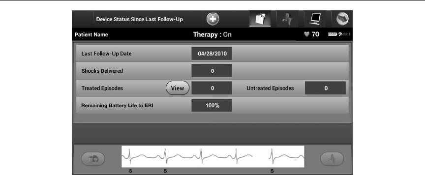
4. The Device Status screen will appear showing an overview of all SQ-RX device activity
since the last communication session (Figure 35).
44
QTECH™ PROGRAMMER: OPERATION
Figure 35: Device Status screen
The Device Status overview reports:
• Date of the last follow-up session
• Total number of shocks delivered since the last follow-up session
• Total number of treated episodes since the last follow-up session
Note: Choosing the “View” button in the Treated Episodes row allows navigation
directly to the list of stored episodes (Figure 36).
• Total number of untreated episodes since the last follow-up session
• Remaining SQ-RX device battery life
Viewing Stored Episodes
The SQ-RX device stores up to 25 treated and 20 untreated tachycardia episodes, which can be
viewed during a patient’s follow-up session. When the maximum number of episodes is exceeded,
the most recent episode replaces the oldest stored episode; however, the rst treated episode will
not be overwritten.
Note: If a spontaneous episode occurs during a patient’s follow-up session
while the SQ-RX device is wirelessly communicating with the
programmer, the episode will not be stored.
45
QTECH™ PROGRAMMER: OPERATION
To view stored episodes:
1. Select the Main Menu icon.
2. Select the Follow Up button.
3. Select the Captured and Stored Episodes S-ECG icon from the Navigation Bar.
4. Select the Episodes option to access the Episodes screen.
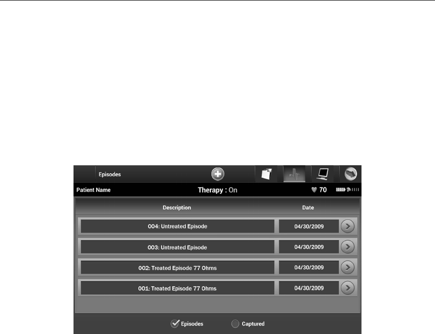
5. Select an episode (treated or untreated) from the list (Figure 36). The selected episode
will be downloaded from the SQ-RX device and displayed.
Note: In order to be available for printing, episodes must be individually
selected and viewed from the Stored Episodes Screen (Figure 36).
Figure 36: Stored Episodes screen (scrollable list)
6. Each selected episode screen also displays the programmed parameters and the
stored S-ECG data at the time of episode declaration.
7. Select the Continue button on the selected episodes screen to return to the Episodes
screen.

46
QTECH™ PROGRAMMER: OPERATION
The following details are available for each episode:
Treated Episodes
Up to 128 seconds of S-ECG data is stored for each Treated Episode:
• Pre-episode S-ECG: Up to 44 seconds
• First shock: Up to 24 seconds of pre-shock S-ECG and up to 12 seconds of post-shock
S-ECG
• Subsequent shocks: 6 seconds of pre-shock and 6 seconds post-shock S-ECG
Untreated Episodes
An Untreated Episode is dened as any high-rate episode that spontaneously terminates
during the charging process, before a shock is delivered.
Up to 128 seconds of S-ECG data is stored for each Untreated Episode:
• Pre-episode S-ECG: 44 seconds of pre-episode S-ECG
• Episode S-ECG: Up to 84 seconds of tachycardia S-ECG data
Printing Reports from the Programmer
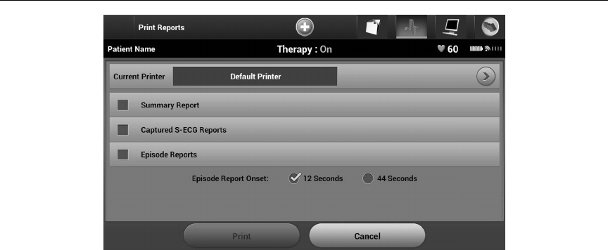
Printing Reports
Patient reports can be printed before or after a patient session is ended. It is recommended that
a nal report be printed immediately following the implant procedure. There are three patient
reports:
• Summary Report
• Captured S-ECG Report
• Episode Reports
To print patient reports from either an Online or Oine session:
1. Select the Main Menu icon to display the Main Menu screen.
2. Select the Print Reports button to display the Print Reports screen (Figure 37).
47
QTECH™ PROGRAMMER: OPERATION
Figure 37: Print Reports screen
3. Select the desired report type. A checkmark will appear next to the selected report.
Report types are described below.
4. Select the Print button to print the selected report.
5. Select the Cancel button to return to the previously accessed screen.
Summary Report
To print a summary report, select the Summary Report option on the Print Reports screen and press
the Print button. The report will print for either the current active session (if the programmer is
online) or for the chosen stored session (if the programmer is oine.)
The Summary Report includes the following information:
• Patient Name
• Date of Current Follow-Up
• Date of Last Follow-Up
• Printed Report Date
• SQ-RX Device Model/Serial Number
• Electrode Model/Serial Number
• Implant Date
48
QTECH™ PROGRAMMER: OPERATION
• Therapy Parameters
• Programmed Gain Settings and Sensing Conguration
• Initial Shock Polarity Conguration
• Episode Summary: Since Last Follow-Up and Since Initial Implant
• Battery Status
• Electrode Impedance Measurement
• SQ-RX Device Integrity Check, if applicable
• Programmer Software Version
• SQ-RX Device Software Version
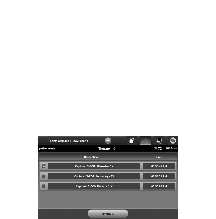
Captured S-ECG Report
To print a Captured S-ECG report:
1. Select the Captured S-ECG Report option from the Print Reports screen
(Figure 37).
2. A list of the captured S-ECG strips is displayed (Figure 38). Select the Captured
S-ECG(s) to be printed. A checkmark appears next to the selected Captured S-ECG.
Figure 38: Captured S-ECG selection screen (scrollable)
49
QTECH™ PROGRAMMER: OPERATION
3. Select Continue to return to the Print Reports screen.
4. Select the Print button to print the selected report.
5. Select the Cancel button to return to the previously accessed screen.
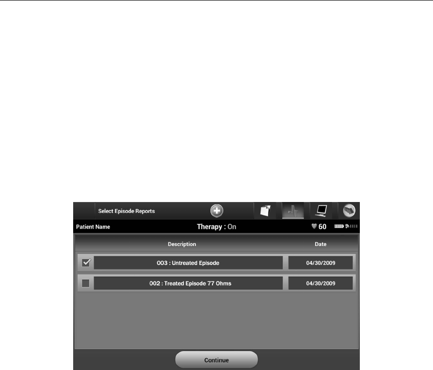
Episodes Report
To print an Episode Report:
1. Select the Episodes Report option on the Print Reports screen (Figure 37).
2. The Episode List screen appears showing a list of the stored episodes (Figure 39).
Select the episode(s) to be printed. A checkmark appears next to the selected
episode(s).
Note: In order to be available for printing, episodes must have been individually
selected and viewed from the Stored Episodes Screen (Figure 36).
Figure 39: Stored Episode List screen (scrollable)
50
QTECH™ PROGRAMMER: OPERATION
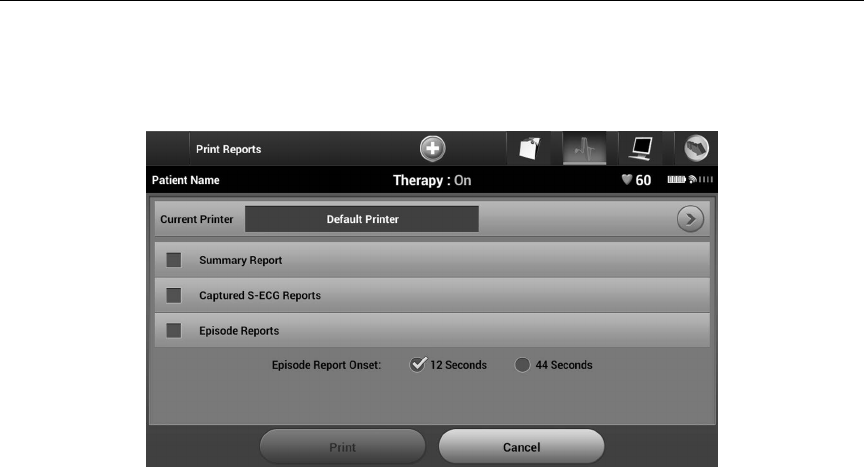
3. Select Continue to return to the Print Reports screen (Figure 40). Either 12 seconds or
44 seconds of pre-episode S-ECG data may be selected using the radio buttons below
the Episode Reports row. The default value for Episode Report Onset is 12 seconds.
Figure 40: Print Reports screen
4. Select the Print button to print the selected report.
5. Select the Cancel button to return to the previously accessed screen.
S-ECG Features
The programmer provides the capability to view, adjust and capture the streaming S-ECG from the
SQ-RX device.
S-ECG Rhythm Strip Markers
The system provides annotations to identify specic events on the S-ECG. These markers are shown
in the S-ECG Markers on Programmer Display Screens and Printed Reports table (Table 2) and an
example is shown in the Sample ECG Markers illustration (Figure 41).
51
QTECH™ PROGRAMMER: OPERATION
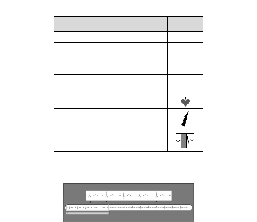
Table 2: S-ECG Markers on Programmer Display Screens and Printed Reports
Description Marker
Charging aC
Sensed Beat S
Noisy Beat N
Paced Beat P
Tachy Detection T
Discard Beat •
Return to NSRa
Shock
Episode data compressed or not available
a Marker present on printed report but not on programmer display screen.
Figure 41: Sample ECG markers
52
QTECH™ PROGRAMMER: OPERATION
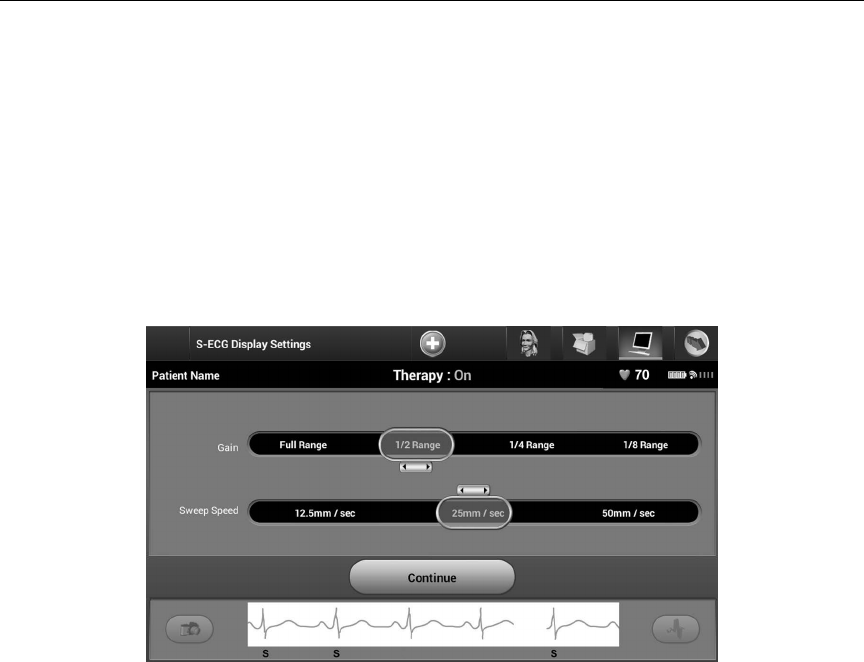
S-ECG Scale Settings
To adjust the real-time S-ECG amplitude and display speed scale settings:
1. Select the S-ECG Display Settings icon located to the right of the Live S-ECG win-
dow. The S-ECG Settings screen is displayed.
2. Select and drag the Gain or Sweep Speed Scale bars as desired (Figure 42). The S-ECG
scale will change according to the selected setting. The gain setting controls the
visual gain. The programmer defaults to Full Range for SQ-RX devices with a gain
setting of x1 and to 1/2 Range for SQ-RX devices with a gain setting of x2. The Sweep
Speed slider controls the display speed of the scrolling Live S-ECG. The nominal
sweep speed setting is 25 mm/sec.
Figure 42: Adjusting Gain and Sweep Speed
Note: Amplitude settings and display speed adjustments on scrolling real-
time S-ECG and Captured S-ECGs aect the display screen settings only
and have no impact on the SQ-RX device settings for sensing.

53
QTECH™ PROGRAMMER: OPERATION
Capture and View S-ECG Strips
The programmer can display, capture and store real-time S-ECG rhythm strips. The programmer
saves a maximum of fteen, 12-second, Captured S-ECG recordings comprised of:
• 8.5 seconds before activation of the Capture S-ECG button
• 3.5 seconds after activation of the Capture S-ECG button
If an additional recording is required, then the oldest previous recording is replaced with the new
recording.
To capture a new S-ECG rhythm strip:
1. Select the Capture S-ECG button located to the left of the Live S-ECG window
(Figure 43). The S-ECG will scroll across the display screen. Calipers appear below the
Captured S-ECG rhythm strip (Figure 44). Each 12-second recording is date and time
stamped according to the programmer’s date and time setting.
Figure 43: Select the Capture S-ECG button
Figure 44: Captured S-ECG rhythm strip

54
QTECH™ PROGRAMMER: OPERATION
2. Select and move the calipers across the S-ECG strip to measure intervals as desired.
3. Select the Continue button to return to the previously accessed screen.
It is also possible to capture S-ECGs corresponding to all three sense vectors (Primary, Secondary,
and Alternate) by using the Capture All Sense Vectors button on the Utilities screen (Figure 45).
To view a previously captured S-ECG:
1. Select the Main Menu icon.
2. Select the Follow Up button.
3. Select the Captured and Stored Episode S-ECG icon. The Captured S-ECG screen
appears.
4. Select one Captured S-ECG from the list. The Captured S-ECG Details screen appears.
5. Select and drag the calipers to view details.
6. Select the Continue button to return to the Captured S-ECG list screen.
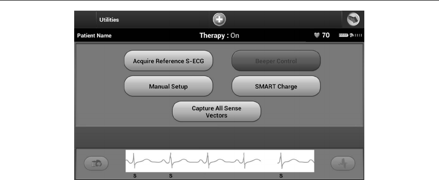
Utilities Menu
The programmer Utilities menu provides access to additional SQ-RX device features. These include
Acquire Reference S-ECG, Capture All Sense Vectors, Beeper Control, Manual Setup and Smart
Charge.
To access the Utilities menu during an Online session:
1. Select the Main Menu icon to display the Main Menu screen.
2. Select the Utilities button. The Utilities screen appears (Figure 45).
55
QTECH™ PROGRAMMER: OPERATION
Figure 45: Utilities screen
Acquire Reference S-ECG
To acquire a manual Reference S-ECG:
1. From the Utilities screen (accessible from the Main Menu screen), select the
Acquire Reference S-ECG button to access the Acquire Reference S-ECG screen.
2. Select Continue to acquire a Reference S-ECG. The programmer will begin acquiring
the Reference S-ECG. A message will appear requesting that the patient remain still
(Figure 46). The reference S-ECG QRS template is recorded and stored in the SQ-RX
device.
3. Select the Continue button to complete the process and return to the Utilities screen.
The Cancel button can be used at any time to end S-ECG acquisition and return to the
Utilities screen.
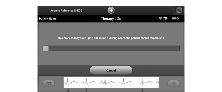
56
QTECH™ PROGRAMMER: OPERATION
Figure 46: The patient should remain still while the Reference S-ECG is acquired
Capture All Sense Vectors
The Capture All Sense Vectors button on the Utilities screen congures temporary programmer
settings that allow you to capture S-ECGs generated from each of the three sense vectors (Primary,
Secondary, and Alternate). This process takes approximately one minute. The programmer returns
to its original settings conguration after all S-ECGs have been captured.
To capture the three sense vectors:
1. From the Utilities screen (accessible from the Main Menu screen), select the
Capture All Sense Vectors button.
2. The Capturing 12 Second S-ECG screen will appear and display the status of the sense
vector capture process (Figure 47).
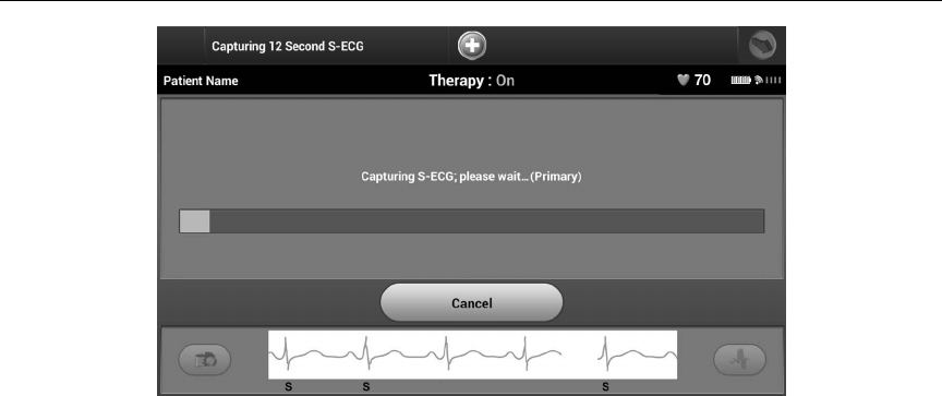
57
QTECH™ PROGRAMMER: OPERATION
Figure 47: Capture all sense vectors
Once captured, the three S-ECGs can be viewed by following the steps outlined in “To view a
previously captured S-ECG” on page 54.
Beeper Control
The SQ-RX device has an internal alert system that emits an audible beeping tone when an alert
condition occurs. Alert conditions may include Elective Replacement Indicator (ERI), End of Life
(EOL), electrode impedance out of range, prolonged charge times, failed Device Integrity Check and
irregular battery depletion. Beeper Control allows activation or suppression of the beeper.
Once an alert condition is triggered, audible tones beep for 16 seconds every nine hours until the
alert condition is resolved. Beeper Control is automatically enabled when the SQ-RX device is taken
out of Shelf mode.
To reset the Beeper Control:
Note: Access to the Beeper Control display screen is enabled only when an alert
condition occurs. If an alert condition is activated, a notication screen
will appear upon connection.
1. From the Utilities screen (accessible from the Main Menu screen), select the
Beeper Control button.
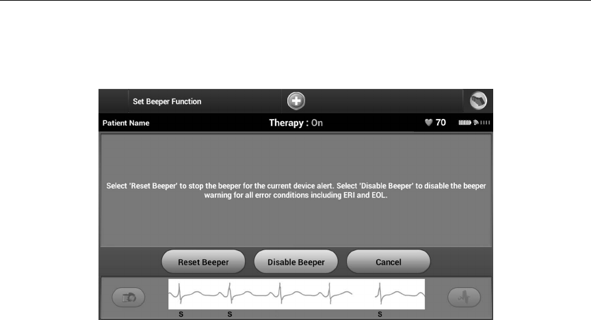
58
QTECH™ PROGRAMMER: OPERATION
2. Select the Reset Beeper button to suspend audible beeping tones triggered by an
alert condition (Figure 48). If the alert condition is not corrected, the audible beeping
tones will be reactivated during the next automatic S-ICD System self-check.
Figure 48: Resetting the Beeper
3. The disable Beeper feature is enabled when ERI is reached or EOL occurs. If desired,
select disable Beeper when ERI or EOL occurs. Beeper tones are permanently
disabled.
Note: If beeper is disabled alert conditions will not trigger audible tones.
Manual Setup
Manual Setup enables the user to perform the electrode integrity test and select the electrode
sensing conguration and gain setting in the SQ-RX device.
1. From the Utilities screen (accessible from the Main Menu screen), select the
Manual Setup button. The Impedance Test screen appears (Figure 49).
2. Select the Test button to perform the electrode integrity test.
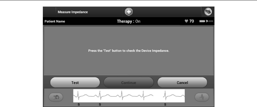
59
QTECH™ PROGRAMMER: OPERATION
Figure 49: Impedance test screen
3. Select Continue to proceed or select Test to retry. The sensing conguration can be
evaluated by temporarily activating any of the vectors or gain settings. The Live S-ECG
and markers will reect the temporary selections for evaluation purposes.
4. There are three available sensing vectors that can be manually selected:
• Primary: Sensing from the proximal electrode ring on the subcutaneous electrode
to the surface of the active SQ-RX device
• Secondary: Sensing from the distal sensing electrode ring on the subcutaneous
electrode to the surface of the active SQ-RX device
• Alternate: Sensing from the distal sensing electrode ring to the proximal sensing
electrode ring on the subcutaneous electrode
The gain setting adjusts the sensed S-ECG signal sensitivity. It may be manually selected via the
Select Gain slider switch (Figure 50).
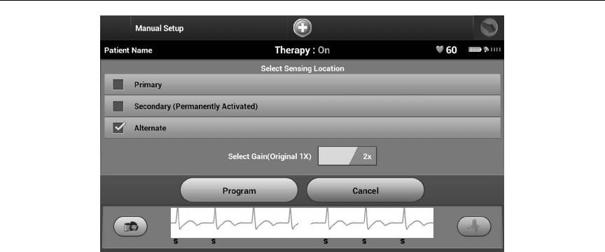
60
QTECH™ PROGRAMMER: OPERATION
Figure 50: Gain adjustment
• 1x Gain (± 4 mV): 1x Gain should be selected when the signal amplitude is large
enough to cause clipping when the 2x gain is selected.
• 2x Gain (± 2 mV): 2x Gain should be selected when the signal amplitude is small
enough to allow use of a more sensitive setting without causing
clipping of the captured signal. The 2x gain selection amplies
the signal twice as much as the 1x gain selection.
To program the manually selected sense conguration:
1. Select the Program button to save the sense vector and gain settings.
2. The Acquire Reference S-ECG process is automatically enabled during the Manual
Setup Process. Select the Continue button to acquire a reference S-ECG. A
conrmation screen will appear when the captured reference S-ECG is acquired
(Figure 51).
3. Select the Continue button.
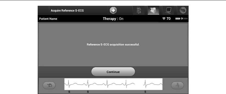
61
QTECH™ PROGRAMMER: OPERATION
Figure 51: Captured Reference S-ECG conrmation
Smart Charge
Through the Smart Charge feature, the SQ-RX device charge initiation sequence adapts to the
occurrence of non-sustained ventricular arrhythmia episodes by delaying capacitor charging. This
conserves battery longevity and may prevent unnecessary shocks for non-sustained arrhythmias.
Smart Charge is enabled automatically when an untreated ventricular arrhythmia episode is
recorded. To reset the Smart Charge feature:
1. From the Utilities screen (accessible from the Main Menu screen), select the
Smart Charge button. The Reset Smart Charge screen appears (Figure 52).
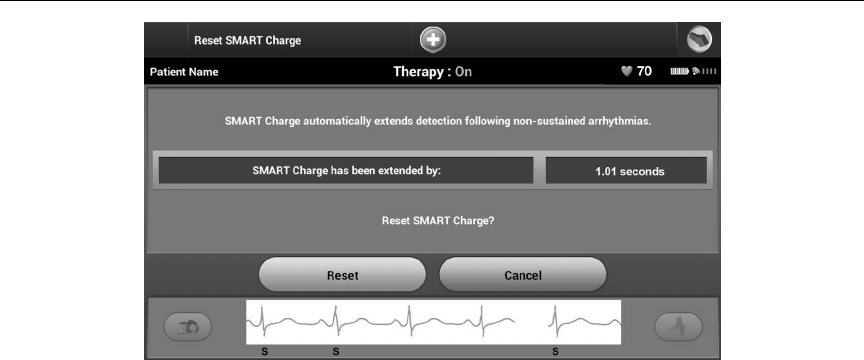
62
QTECH™ PROGRAMMER: OPERATION
Figure 52: Reset Smart Charge screen
2. Select the Reset button to reset the Smart Charge to zero or press Cancel to return to
the Utilities Menu without resetting the Smart Charge.
3. A conrmation window will appear with the message: “Smart Charge successfully
reset.”
4. Press the Continue button to return to the Utilities screen.
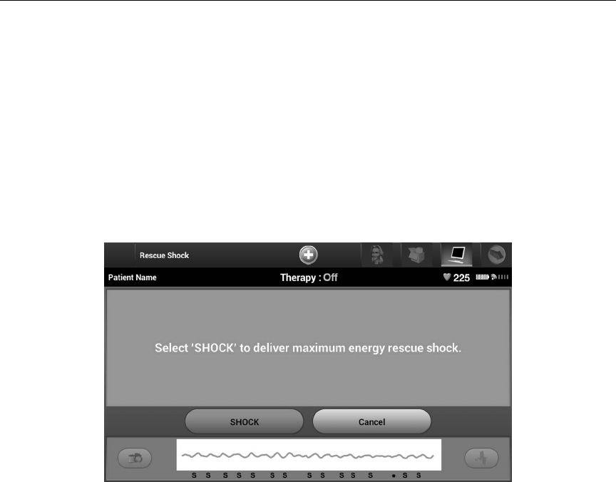
63
QTECH™ PROGRAMMER: OPERATION
Additional Programmer Functions
Rescue Shock
The Rescue Shock icon is available in the navigation bar on the programmer display when the
SQ-RX device Setup Process is complete and an SQ-RX device is actively communicating with the
programmer. During active communication, a maximum (80 J) rescue shock can be delivered upon
programmer command.
To deliver a rescue shock:
1. Select the red Rescue Icon at the top of the programmer screen. The Rescue
Shock screen appears (Figure 53).
Figure 53: Rescue Shock screen
2. Select the Shock button to begin charging the SQ-RX device for a Rescue shock. A
red background screen with the word “Charging” will appear (Figure 54). Selecting
the Abort button will prevent delivery of a rescue shock and will return to the Device
Settings screen.
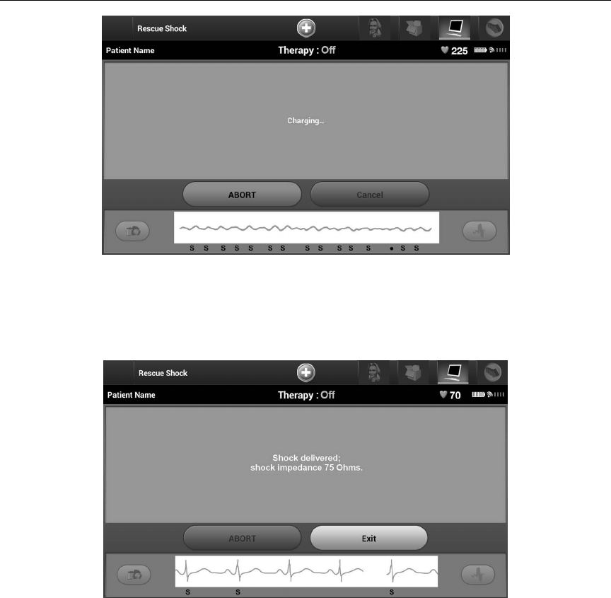
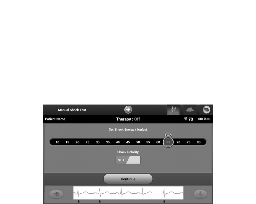
65
QTECH™ PROGRAMMER: OPERATION
If for any reason the shock could not be delivered, a red background screen will appear with a
message stating “The Shock could not be delivered.”
Note: In the event telemetry is lost, SQ-RX device commands, including Rescue
Shocks, will not be available until telemetry is reestablished.
Manual shock
Manual Shock allows the user to deliver a synchronized shock during a sinus rhythm, an atrial
rhythm or a ventricular rhythm. The shock energy level is user-congured in the 10 to 80 joule range
(Figure 56). Manual shock may also be utilized at a low energy to assess system impedance/integrity
either at implant or as warranted by patient condition. A manual shock may be administered with
the S-ICD detection zone(s) either ON or OFF.
Figure 56: Manual shock
S-ICD System Magnet Model 4520
Model 4520 Magnet (the “magnet”) is a nonsterile accessory used to inhibit the delivery of therapy
from the SQ-RX device. Apply the magnet at against the skin directly over the implanted SQ-RX
device for a minimum of one (1) second to suspend arrhythmia detection. Removal of the magnet
will return the SQ-RX device to normal operation. If the magnet is applied during an episode, the
episode will not be stored in the SQ-RX device memory.

66
QTECH™ PROGRAMMER: OPERATION / MAINTENANCE
Other behaviors of magnet application:
• Inhibit shock therapy delivery
• Terminate post-shock pacing therapy
• Prohibit arrhythmia induction testing
• Activate the SQ-RX device’s beeper with each detected QRS complex for 60 seconds
Note: A programmer commanded Rescue Shock can override the use of the
magnet as long as the magnet was in place prior to the initiation of
the programming command. If the magnet is applied after the initial
command, the Rescue Shock will be terminated.
Note: Magnet application does not aect wireless communication between
the SQ-RX device and the programmer.
MAINTENANCE
Charging the Programmer
When not in use, it is recommended that the programmer remain connected to the external power
supply. This will ensure that the internal battery is adequately charged.
Cleaning the Programmer
Keep the programmer away from dust and dirt. Do not use harsh chemicals, cleaning solvents, or
strong detergents to clean the programmer and wand.
To clean the programmer and wand as needed:
1. Turn the Programmer O.
2. Gently wipe the programmer screen with a soft, clean, dry cloth.
3. Clean the programmer plastic case and the wand by wiping them with an isopropyl
alcohol-moistened cloth.
4. Dry the programmer immediately to remove residue.
Service
There are no user-accessible or user-serviceable parts or components in the programmer. If
any service, repair, or replacement of internal components is needed, the programmer must be
returned to Cameron Health/Boston Scientic. Contact your Cameron Health/Boston Scientic
Representative or the customer service department for instructions and return packaging.

67
QTECH™ PROGRAMMER: MAINTENANCE
When requesting service, please provide information concerning the nature of the failure and the
manner in which the equipment was used when the failure occurred. The model number and serial
number should also be provided. Before returning any products to the factory, call Cameron Health/
Boston Scientic customer service or your local representative for a Return Authorization number.
Maintenance Check
Prior to each use, you should perform a visual inspection and verify the following:
• Mechanical and functional integrity of the programmer, cables, and accessories.
• Legibility and adherence of the programmer labels.
• Startup screen appears a few seconds after you turn on the programmer. (The normal power-
up process veries that the programmer has passed its internal checks and is ready for use.)
Safety Measurements
National regulations may require that the user, manufacturer, or manufacturer representative
periodically perform and document safety tests of the programmer. If such testing is required in
your country, follow the testing interval and extent of testing as regulated in your country. If you
do not know the national regulations in your country, please contact your Cameron Health/Boston
Scientic representative. If IEC/EN 62353 is a required standard in your country, but no specic
testing or interval is specied, it is recommended that you perform these safety tests using the
direct method as specied in IEC/EN 62353 at an interval of every 24 months. Test values are shown
in the Nominal Specications table (Table 11).
Programmer End of Life
The programmer and accessories are designed to provide years of service under typical use. To
dispose of, return, or exchange a programmer, contact your Cameron Health/Boston Scientic
representative or the customer service department for instructions and return packaging. Do not
dispose of the programmer in the trash or at electronics recycling facilities.

68
QTECH™ PROGRAMMER: TROUBLESHOOTING
TROUBLESHOOTING
This section presents potential programmer issues and the possible solutions. Of note, restarting
the programmer can often resolve many of the issues listed below. The programmer can be
restarted by pressing and holding the power button until the system shutdown menu appears and
then choosing the “Restart” option.
Contact your Cameron Health/Boston Scientic representative or the customer service department
for additional assistance.
Inability to Print
If unable to print, follow the steps below:
1. Ensure that the printer is turned On and that it contains paper and a sucient ink
supply.
2. Check printer feed for paper jam.
3. Ensure, as applicable, that the wireless function is enabled on the printer or that the Cameron
Health/Boston Scientic approved wireless adapter is fully inserted into the left side of the
printer.
No Printer Available
The No Printer Available screen will appear if a printer was not set up. Select the Try Again button or
refer to the Printer Selection section for instructions.
Touch Screen Inactive while Connected to AC Power
If the touch screen does not function while the programmer is connected AC power via the external
power supply, disconnect and reconnect the external power supply and restart the programmer.
Loss of Communication with Printer
When communication between the programmer and the printer fails, a Printing Error screen will
appear with a message stating “Error while printing reports. Press “Continue” to try printing any
remaining reports, or “Cancel” to cancel the current print job.”

69
QTECH™ PROGRAMMER: TROUBLESHOOTING
If this occurs:
1. Select the Try Again button to reconnect to the printer.
2. Verify that the selected printer has, as applicable, the wireless function enabled or a
Cameron Health-approved wireless adapter inserted in the left side of the printer.
3. Move the programmer closer to the printer.
4. Move any devices and the associated cables that may be interfering with the RF
communication.
Inability to Communicate With the SQ-RX Device
If the programmer is unable to communicate with the SQ-RX device, follow the steps below:
1. Attempt to reposition the wand.
2. Select Scan For Devices from the Main Menu or select Scan Again from the Device List
screen to locate the desired SQ-RX device.
3. Move any equipment and associated cables that may be interfering with RF
communication.
4. If available, attempt to communicate using a dierent S-ICD System programmer
and/or wand.
5. Apply a pulse generator magnet to the SQ-RX device to elicit beeper tones. Remove
the magnet and re-attempt communication.

70
QTECH™ PROGRAMMER: COMPLIANCE STATEMENTS
Federal Communications Commission (FCC) US
This transmitter is authorized by rule under the Medical Device Radiocommunication Service (in part
95 of the FCC Rules) and must not cause harmful interference to stations operating in the 400.150 -
406.00 MHz band in the Meteorological Aids (i.e., transmitters and receivers used to communicate
weather data), the Meteorological Satellite, or the Earth Exploration Satellite Services and must accept
interference that may be caused by such stations, including interference that may cause undesired
operation. This transmitter shall be used only in accordance with the FCC Rules governing the Medical
Device Radiocommunication Service. Analog and digital voice communications are prohibited.
Although this transmitter has been approved by the Federal Communications Commission, there is no
guarantee that it will not receive interference or that any particular transmission from this transmitter
will be free from interference.
The Bluetooth® module contained within the Model 3200 programmer complies with Title 47, Part 15 of
the FCC rules. Operation is subject to the following two conditions:
• This device may not cause harmful interference, and
• This device must accept any interference received, including interference that may cause
undesired operation.
FCC ID SDYCHI2020
Contains: FCC ID ESCCRM70514
CAUTION: Changes or modications not expressly approved by Cameron Health / Boston Scientic
could void the user’s authority to operate the equipment.
Essential Performance
In order for the Model 3200 Programmer to meet its intended use, it must interrogate and maintain a
communications link with a supported pulse generator as well as being able to appropriately detect
touch screen button presses. Therefore those functions that pertain to communications with the
implanted cardioverter debrillator and detection of touch screen presses are considered essential
performance.
COMPLIANCE STATEMENTS

71
QTECH™ PROGRAMMER: COMPLIANCE STATEMENTS
EMI/RFI
This equipment has been tested and found to comply with the applicable limits for medical devices, IEC
60601-1-2:2007 or Active Implantable Medical Device Directive 90/385/EEC.
Although this testing shows the device to provide reasonable protection against harmful interference
in a typical medical installation, there is no guarantee that interference will not occur in a particular
installation. If the device does cause harmful interference the user is encouraged to try and correct the
interference by the following measures:
• Reorient or relocate the device
• Increase the separation between the devices
• Connect the equipment to an outlet on a dierent circuit
• Contact your Cameron Health/Boston Scientic representative or customer service.

72
QTECH™ PROGRAMMER: DECLARATIONS TABLES
Table 4: Declaration Electromagnetic Immunity Part 1
Table 3: Declaration Electromagnetic Emission
The Q-TECH Model 3200 programmer is intended for use in the electromagnetic environment specied below. The customer or the user of the Q-TECH
Model 3200 should assure that it is used in such an environment.
Emissions Test Compliance Electromagnetic Environment Guidance
RF Emissions CISPR 11 Group 1 The Q-TECH Model 3200 programmer uses RF energy only for its internal
function. Therefore, its RF emissions are very low and are not likely to cause
any interference in nearby electronic equipment.
RF Emissions CISPR 11 Class A The Q-TECH Model 3200 programmer is suitable for use in all establishments
other than domestic and those directly connected to the public low-voltage
power supply network that supplies buildings used for domestic purposes.
Harmonic Emissions IEC 61000-3-2 Class A
Voltage Fluctuations/Flicker Emissions IEC 61000-3-3 Complies
The Q-TECH Model 3200 programmer is intended for use in the electromagnetic environment specied below. The customer or the user of the Q-TECH Model 3200
should assure that it is used in such an environment.
Immunity Test IEC 60601
Test Level
Compliance Level Electromagnetic Environment
Guidance
Electrostatic Discharge
(ESD)
IEC 61000-4-2
± 6 kV contact
± 8 kV air
± 6 kV contact
± 8 kV air
Floors should be wood, concrete, or
ceramic tile. If oors are covered
with synthetic material, then the
relative humidity should be at least
30%.
Electrical Fast
Transient/Burst
IEC 61000-4-4
± 2 kV for power supply lines
± 1 kV for input/output lines
± 2 kV for power supply lines
± 1 kV for input/output lines
Mains power quality should be that
of a typical commercial or hospital
environment.
Surge
IEC 61000-4-5
± 1 kV line(s) to line(s)
± 2 kV line(s) to earth
± 1 kV line(s) to line(s)
± 2 kV line(s) to earth
Mains power quality should be that of a
typical commercial or hospital environment.
Voltage Dips, Short
interruptions, and voltage
variations on power
supply input lines
IEC 61000-4-11
<5% UT (>95% dip in UT) for 0.5 cycles
40% UT (60% dip in UT) for 5 cycles
70% UT 30% dip in UT) or 25 cycles
<5% UT (>95% dip in UT) for 5 sec
<5% UT (>95% dip in UT) for 0.5 cycles
40% UT (60% dip in UT) for 5 cycles
70% UT (30% dip in UT) for 25 cycles
<5% UT (>95% dip in UT) for 5 sec
Mains power quality should be that of a
typical commercial or hospital environment.
If the user of the Q-TECH Model 3200
programmer requires continued operation
during power mains interruptions, it is
recommended that the Q-TECH Model
3200 programmer be powered from an
uninterruptible power supply or a battery.
Power Frequency (50/60
Hz) Magnetic Fields
IEC 61000-4-8
3 A/m 3 A/m Power frequency magnetic elds should
be at levels characteristic of a typical
location in a typical commercial or hospital
environment.
NOTE: UT is the a.c. mains voltage prior to application of the test level.
73
QTECH™ PROGRAMMER: DECLARATIONS TABLES
Table 5: Declaration Electromagnetic Immunity Part 2
The Q-TECH Model 3200 programmer is intended for use in the electromagnetic environment specied below. The customer or the user of the Q-TECH Model 3200
should assure that it is used in such an environment.
Immunity Test IEC 60601 Test
Level
Compliance
Level
Electromagnetic Environment Guidance
Conducted RF
IEC 61000-4-6
3 Vrms
150 kHz to
80 MHz
3 V Portable and mobile RF communications equipment should be used no closer
to any part of the Q-TECH Model 3200 programmer, including cables, than the
recommended separation distance calculated from the equation applicable to the
frequency of the transmitter.
Recommended Separation Distance
3,5
V1
√ P
d
= []
3,5
E1
√ P
d
= []
7
E1
√ P
d
= []
80 MHz to 800 MHz
800 MHz to 2.5 GHz
150 KHz to 80 MHz
where P is the maximum output power rating of the transmitter in watts (W)
according to the transmitter manufacturer and d is the recommended separation
distance in meters (m).
Field strengths from xed RF transmitters, as determined by an electromagnetic
site survey,a should be less than the compliance level in each frequency range.b
Interference may occur in the vicinity of equipment marked with the following
symbol:
Radiated RF
IEC 61000-4-3
3 V/m
80 MHz to
2.5 GHz
3 V/m
Note 1: At 80 MHz and 800 MHz, the higher frequency range applies.
Note 2: These guidelines may not apply in all situations. Electromagnetic propagation is aected by absorption and reection from structures, objects and people.
a Field strengths from xed transmitters, such as base stations for radio (cellular/cordless) telephones and land mobile radios, amateur
radio, AM and FM radio broadcast and TV broadcast cannot be predicted theoretically with accuracy. To assess the electromagnetic
environment due to xed RF transmitters, an electromagnetic site survey should be considered. If the measured eld strength in the
location in which the Q-TECH Model 3200 is used exceeds the applicable RF compliance level above, the Q-TECH Model 3200 should be
observed to verify normal operation. If abnormal performance is observed, additional measures may be necessary, such as reorienting
or relocating the Q-TECH Model 3200.
b Over the frequency range 150 kHz to 80 MHz, eld strengths should be less than 3 V/m
74
QTECH™ PROGRAMMER: DECLARATIONS TABLES
Table 8: EMI/RFI Information: Programmer–to–printer (Bluetooth®)
Specication Bluetooth® 4.0 wireless technology
Frequency band 2.402-2.480 GHz
Modulation type GFSK, π/4-DQPSK, 8DPSK
Radiated power <100 mW
Bandwidth < 1 MHz
Table 6: Recommended Separation Distances
Recommended separation distances between portable and mobile RF communications equipment and the Q-TECH
Model 3200 programmer
The Q-TECH Model 3200 programmer is intended for use in an electromagnetic environment in which radiated RF disturbances are controlled. The customer or the
user of the Q-TECH Model 3200 programmer can help prevent electromagnetic interference by maintaining a minimum distance between portable and mobile
RF communications equipment (transmitters) and the Q-TECH Model 3200 programmer as recommended below, according to the maximum output power of the
communications equipment.
Rated maximum output power
of transmitter
W
Separation distance according to frequency of transmitter
m
150 KHz to 80 MHz
3,5
V1
√ P
d
= []
80 MHz to 800 MHz
3,5
E1
√ P
d
= []
800 MHz to 2.5 GHz
0.01 0.117 0.117 0.233
0.1 0.369 0.369 0.738
1 1.17 1.17 2.34
10 3.69 3.69 7.38
100 11.7 11.7 23.3
For transmitters rated at a maximum output power not listed above, the recommended separation distance d in metres (m) can be estimated using the
equation applicable to the frequency of the transmitter, where p is the maximum output power rating of the transmitter in watts (W) according to the
transmitter manufacturer.
Note 1: At 80 MHz and 800 MHz, the separation distance for the higher frequency range applies.
Note 2: These guidelines may not apply in all situations. Electromagnetic propagation is aected by absorption and reection from structures, objects and people.
7
E1
√ P
d
= []
Table 7: EMI/RFI Information: Programmer–to–pulse generator
Specication Medical Implant Communications Service (MICS)
Frequency band 402-405 MHz
Modulation type FSK
Radiated Power <25 μW
Bandwidth < 300 KHz

75
QTECH™ PROGRAMMER: SPECIFICATIONS
Table 9: Product Guidelines
Component Requirement
DC Power
Battery pack type 4000 mAh 3.7 volt lithium-ion battery pack
Charge time Approximately 5 hours
Power Supply
Input 100 – 240 VAC, 50 - 60 Hz, 0.5A
Output 5.5 VDC, 3.64A
Power: 20 W
Manufacturer/Model Elpac Power Systems MWA020005A
Environment Operating Storage
Temperature 15° C to +38° C
(+59° F to +100° F)
-10° C to +55° C
(+14° F to +131° F)
Relative humidity 5% to 93% maximum at 40° C,
non-condensing
5% to 93% maximum at 40° C,
non-condensing
Atmospheric pressure 50 kPa to 106 kPa
(7.252 psi to 15.374 psi)
50 kPa to 106 kPa
(7.252 psi to 15.374 psi)
Table 10: Specications
Component Specication
Dimensions
Width x Depth x Height
24.0 cm x 12.7 cm x 2.6 cm
9.4 in x 5.0 in x 1.0 in
Weight .6 kg, 1.3 lbs
Standard Screen Display WVGA, 1024 x 600 pixels, 16M TFT

76
QTECH™ PROGRAMMER: SPECIFICATIONS
Table 11: Nominal Specications
Characteristic Nominal
Electrical Safety Testing – IEC 60601-1:2005 / ANSI/AAMI ES60601-1:2005 allowed values
Earth resistance 100 mΩ
Earth leakage current 5 mA Normal Condition (NC)
10 mA Single Fault Condition (SFC)
Patient leakage current 100 μA Normal Condition (NC)
500 μA Single Fault Condition (SFC) (mains on applied parts)
Electrical Safety Testing – IEC 62353:2008 allowed values
Earthbond testing (Groundbond testing) 300 mΩ including power cable not exceeding 3 meters
Equipment leakage — direct method 500 μA
Patient leakage current — direct method
(Wand, BF)
<= 5000 μA
Safety Features
Debrillator protection to 5000 V, 400 J
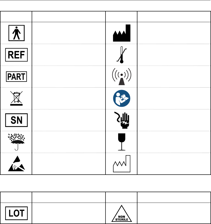
77
QTECH™ PROGRAMMER: DEFINITION OF PACKAGE LABEL SYMBOLS
Table 12: Packaging Symbols: Q-TECH Programmer
Symbol Specication Symbol Specication
Type BF Applied Part Symbol – Indicates
connection of Type BF applied part
Manufacturer – Name and address of the
manufacturer
Reference Number - Catalog number Storage Temperature - Product stored with
temperature limitations
Part Number - Component number Radio – Non-ionizing electromagnetic
radiation
Do Not Dispose – Do not dispose of in trash Follow instructions for use
Serial Number – Serial number of the
programmer
Risk Of Shock – Indicates the risk of electric
shock
Keep Dry - Ship and store in a dry place Fragile: Handle with Care - Transport and
store with care
Electrostatic Discharge – Identies
a connector not tested for immunity to
electrostatic discharge
Date of Manufacture – Date programmer
was manufactured
Table 13: Packaging Symbols: Q-TECH Programmer Wand
Symbol Specication Symbol Specication
Lot number – Batch code Non-Sterile – Used to indicate the product is
not sterile

78
QTECH™ PROGRAMMER: WARRANTY
Limited Warranty
A limited warranty may apply to this programmer. For warranty eligibility and to obtain a copy of the
limited warranty, contact Boston Scientic / Cameron Health using the information on the back cover.