Boston Scientific CRMA20914 A209 User Manual
Boston Scientific Corporation A209
UserManual.wiki
>
Boston Scientific
>
CRMA20914 User Manual
User Manual
Navigation menu
Upload a User Manual
Namespaces
Wiki Guide
HTML
PDF
Info
Views
User Manual
Discussion / Help
Navigation
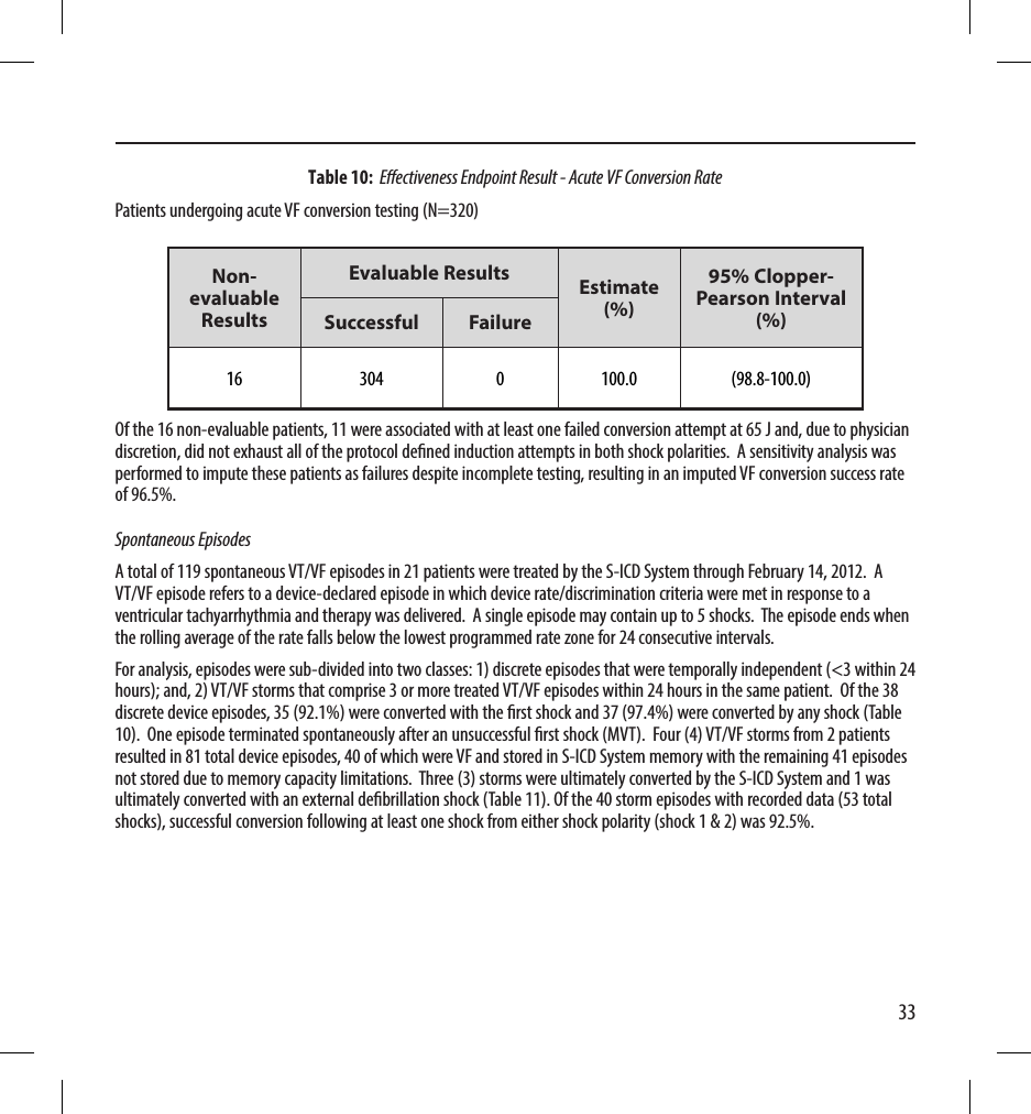
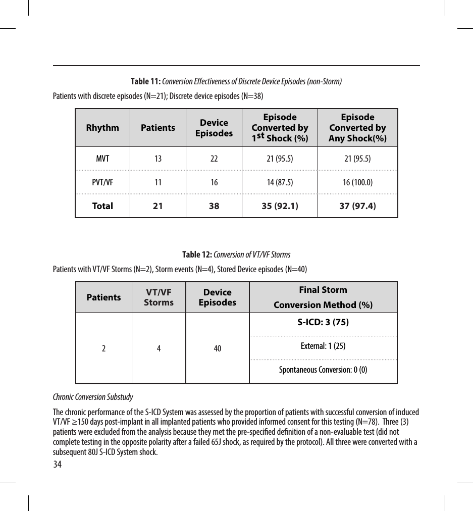
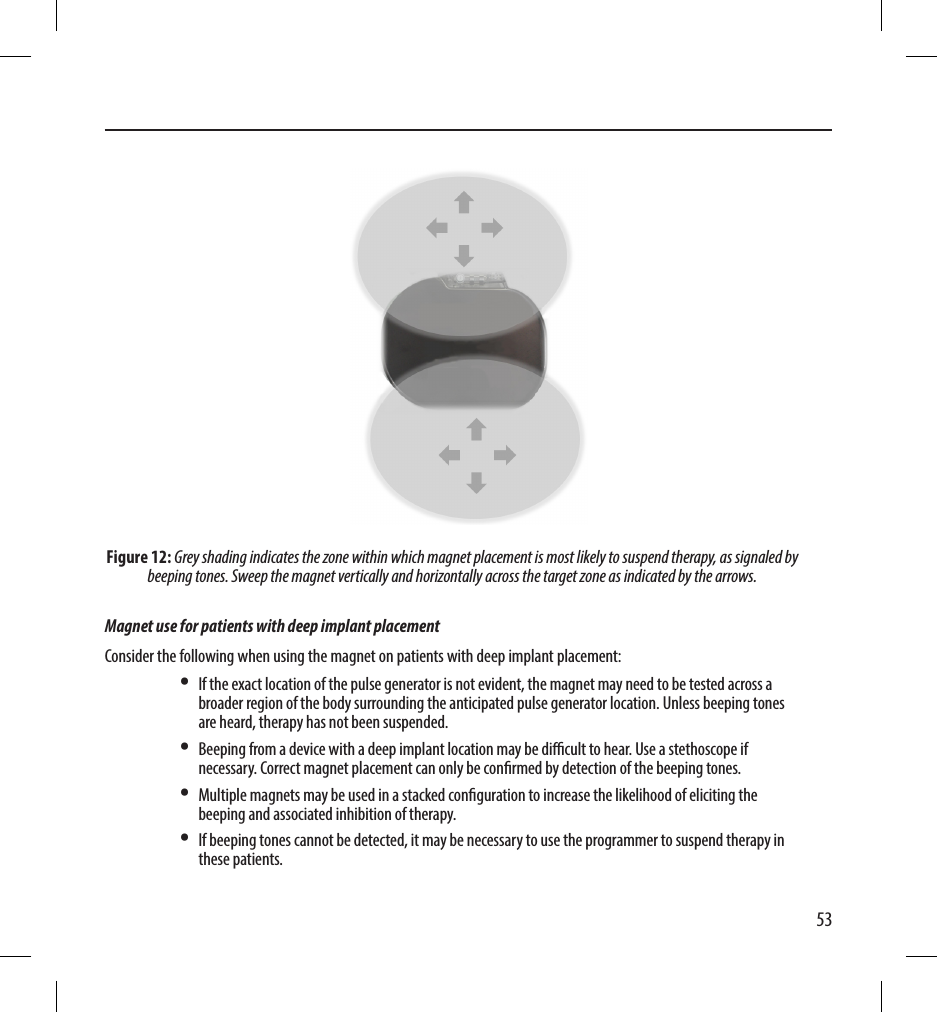
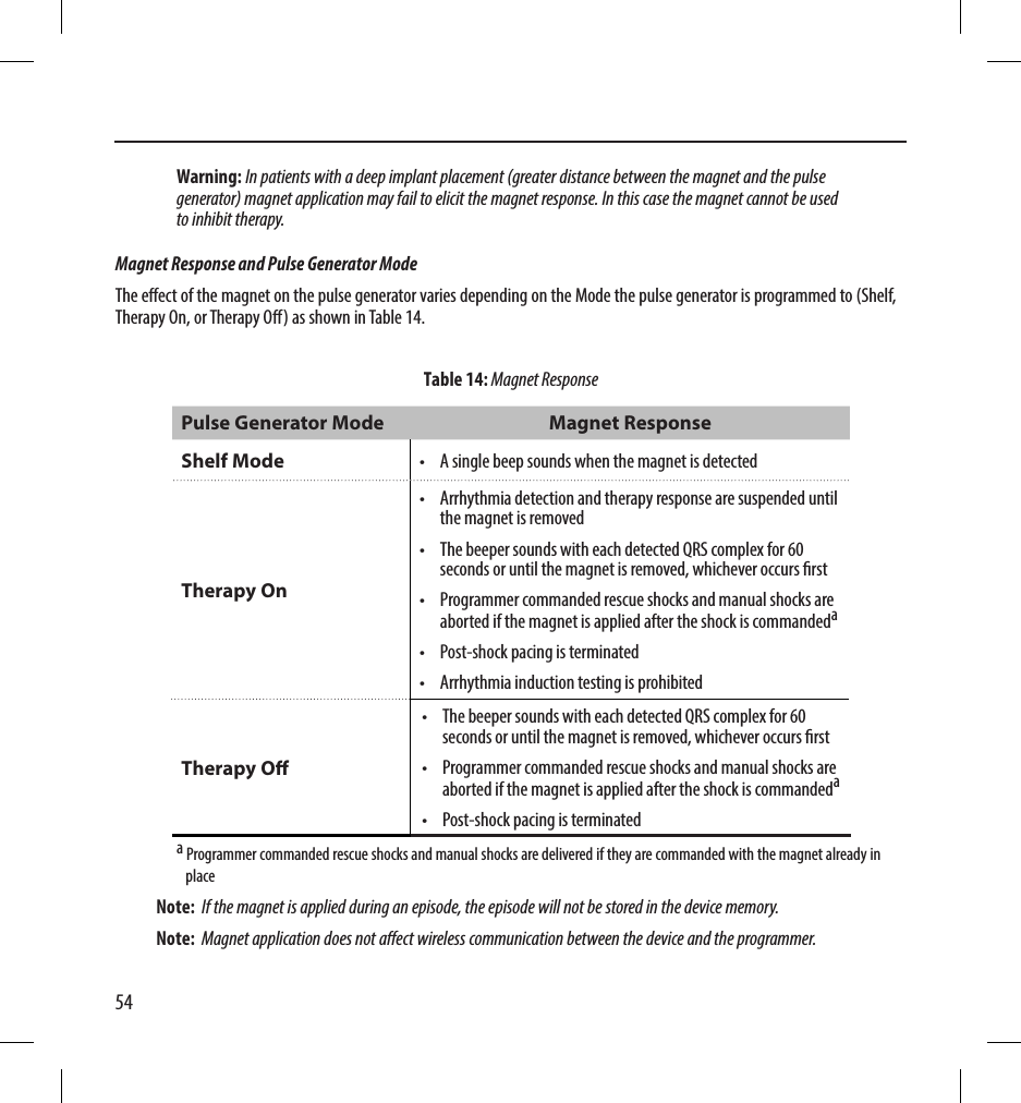
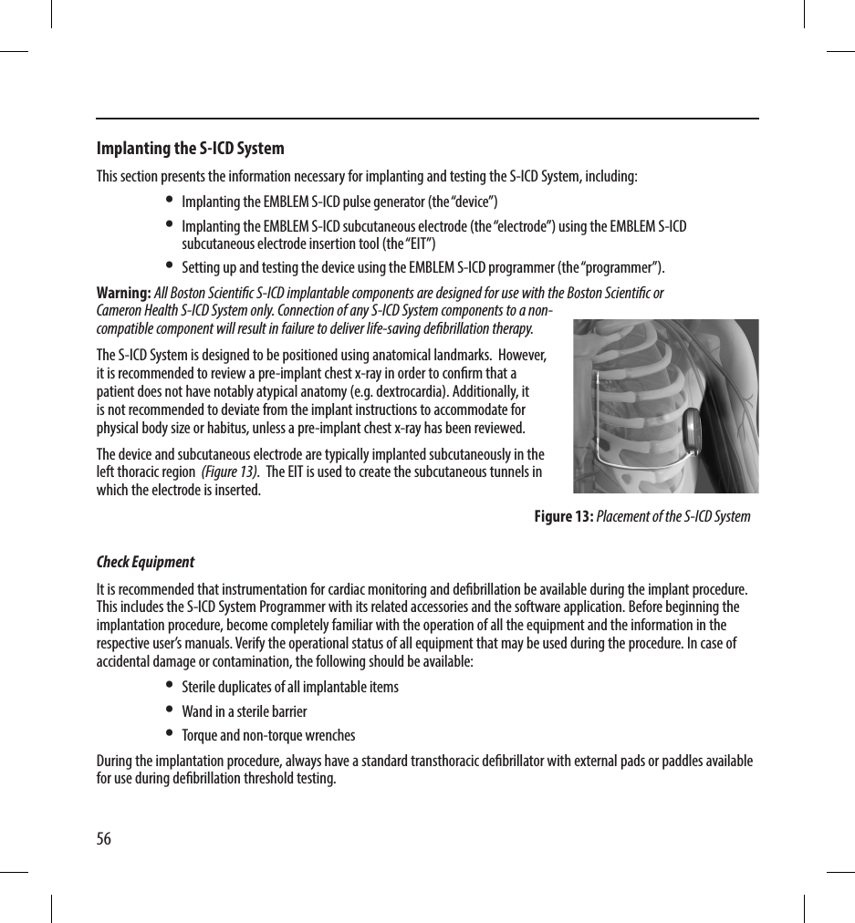
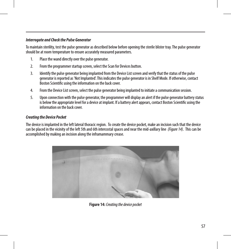
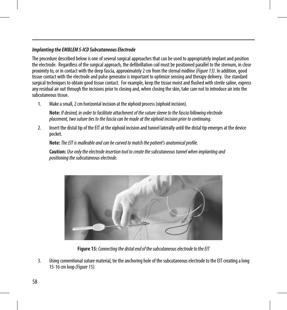
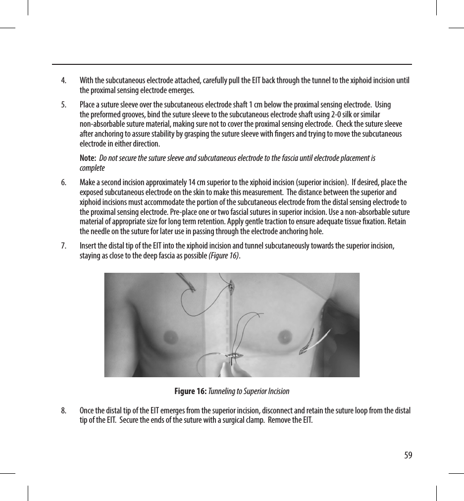
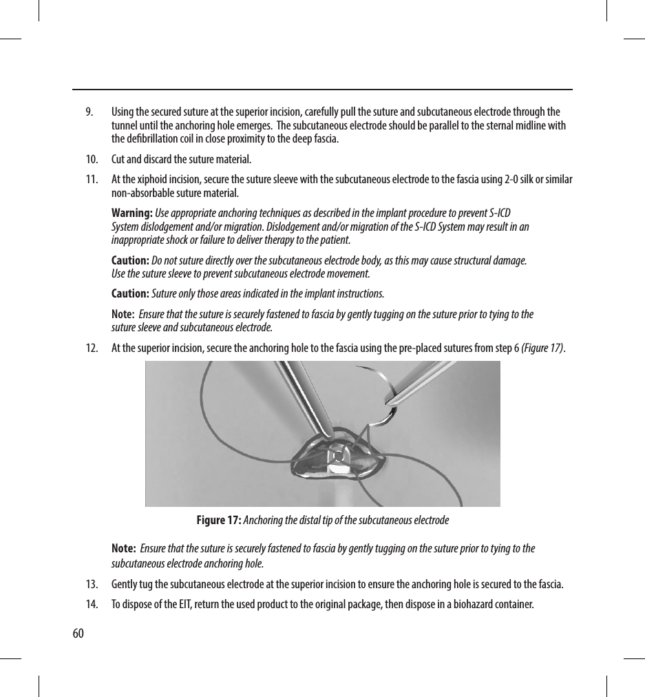
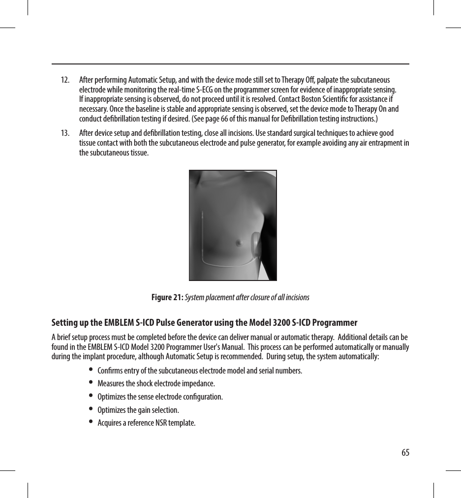
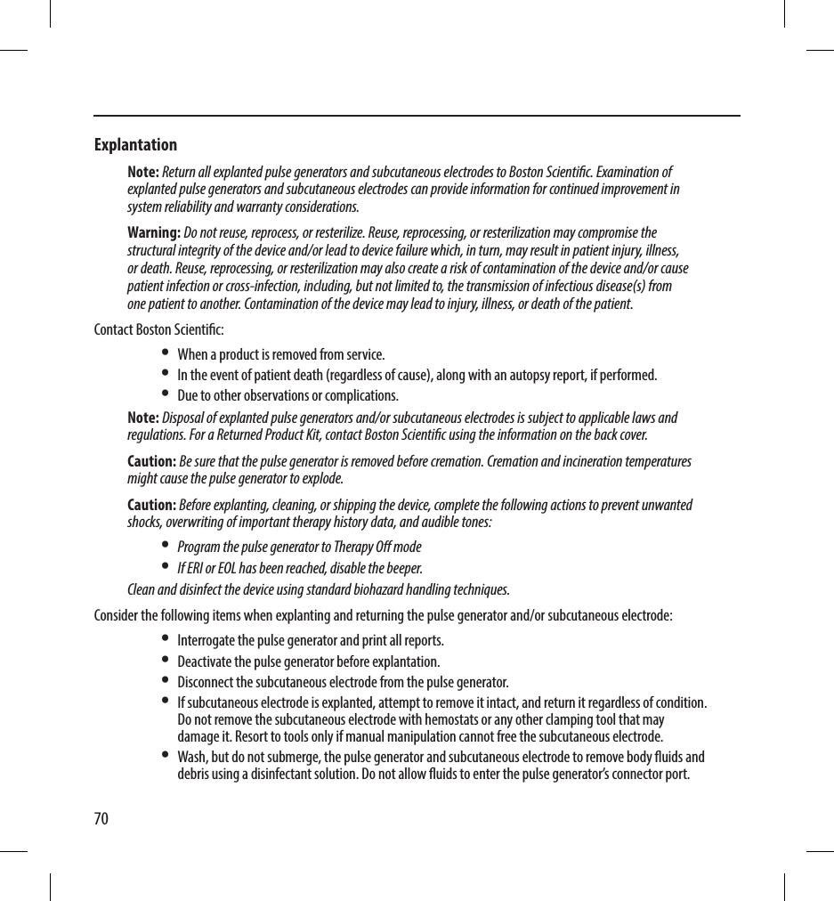
![71• Use a Boston Scientic Returned Product Kit to properly package the pulse generator and/or subcutaneous electrode, and send it to Boston Scientic.Loosening Stuck SetscrewsFollow these steps to loosen stuck setscrews:1. From a perpendicular position, tilt the torque wrench to the side 20º to 30º from the vertical center axis of the setscrew (Figure 22).2. Rotate the wrench clockwise (for retracted setscrew) or counterclockwise (for extended setscrew) around the axis three times, such that the handle of the wrench orbits the centerline of the screw (Figure 20). The torque wrench handle should not turn or twist during this rotation.[1] Clockwise rotation to free setscrews stuck in the retracted position [2] Counterclockwise rotation to free setscrews stuck in the extended positionFigure 22: Rotating the torque wrench to loosen a stuck setscrew3. As needed, you may attempt this up to four times with slightly more angle each time. If you cannot fully loosen the setscrew, use the #2 torque wrench from Wrench Kit Model 6501.4. Once the setscrew has been freed, it may be extended or retracted as appropriate.5. Discard the torque wrench upon completion of this procedure.](https://usermanual.wiki/Boston-Scientific/CRMA20914/User-Guide-2474429-Page-77.png)