Boston Scientific CRMA20914 A209 User Manual
Boston Scientific Corporation A209
User Manual

PULSE GENERATOR USER'S MANUAL
EMBLEM™ S-ICD
Subcutaneous Implantable Cardioverter Debrillator
MODEL A209
CAUTION: Federal law (USA) restricts this device to sale
by or on the order of a physician trained or experienced in
device implant and follow-up procedures.

EMBLEM is a trademark of Boston Scientic.
This product may be protected by one or more patents. Patent information can be obtained at http://www.
bostonscientic.com/patents.
List of Acronyms
ATP Anti-tachycardia pacing
BOL Beginning of life
CPR Cardiopulmonary resuscitation
CRT Cardiac resynchronization therapy
DFT Debrillation threshold
EAS Electronic article surveillance
ECG Electrocardiogram
EGM Electrogram
EIT Electrode insertion tool
EMI Electromagnetic interference
EOL End of life
ERI Elective replacement indicator
ESWL Extracorporeal shock wave lithotripsy
FCC Federal Communications Commission
HBOT Hyperbaric oxygen therapy
MRI Magnetic resonance imaging
NSR Normal sinus rhythm
PVC Premature ventricular contraction
S-ECG Subcutaneous electrocardiogram
S-ICD Subcutaneous implantable cardioverter debrillator
SVT Supraventricular tachycardia
TENS Transcutaneous electrical nerve stimulation
VF Ventricular brillation
VT Ventricular tachycardia

Table of Contents
Description 1
Related Information 1
Intended Audience 1
Indications for Use 1
Contraindications 1
Warnings 1
General 1
Handling 2
Implantation 2
Post-Implant 3
Precautions 3
Clinical Considerations 3
Sterilization and Storage 4
Implantation 4
Device Programming 5
Environmental and Medical Therapy Hazards 6
Hospital and Medical Environments 6
Home and Occupational Environments 10
Follow-up Testing 12
Explant and Disposal 12
Supplemental Precautionary Information 12
Potential Adverse Events 13
Clinical Summary 15
S-ICD System Clinical Investigation 15
Methods 15
Primary Objectives 15
Additional Objectives 16
Accountability of PMA Cohort 17
Study Population Demographics and Baseline Parameters 18

Safety and Eectiveness Results 24
Eectiveness Results 32
Subgroup Analyses 35
Conclusion 36
Patient Screening 37
Collecting the Surface ECG 37
Evaluating the Surface ECG 38
Determining an Acceptable Sense Vector 40
Operation 41
General 41
Modes of Operation 41
Shelf Mode 41
Therapy On Mode 41
Therapy O Mode 41
Sensing Conguration and Gain Selection 42
Sensing and Tachyarrhythmia Detection 42
Detection Phase 42
Certication Phase 43
Decision Phase 43
Therapy Zones 43
Analysis in the Conditional Shock Zone 44
Charge Conrmation 45
Therapy Delivery 45
Smart Charge 45
Redetection 46
Shock Waveform and Polarity 46
Post-Shock Bradycardia Pacing Therapy 46
Manual and Rescue Shock Delivery 46
Additional Features of the S-ICD System 46
Auto Capacitor Reformation 47
Internal Warning System – Beeper Control 47

Arrhythmia Induction 47
System Diagnostics 47
Subcutaneous Electrode Impedance 48
Device Integrity Check 48
Battery Performance Monitoring System 48
Storing and Analyzing Data 49
Treated Episodes 49
Untreated Episodes 49
Captured S-ECG 49
S-ECG Rhythm Strip Markers 50
Patient Data 51
S-ICD System Magnet Use 52
Magnet use for patients with deep implant placement 53
Magnet Response and Pulse Generator Mode 54
Bidirectional Torque Wrench 55
Using the EMBLEM S-ICD Pulse Generator 55
Items Included in Package 55
Implanting the S-ICD System 56
Check Equipment 56
Interrogate and Check the Pulse Generator 57
Creating the Device Pocket 57
Implanting the EMBLEM S-ICD Subcutaneous Electrode 58
Connecting the Subcutaneous Electrode to the Device 61
Setting up the EMBLEM S-ICD Pulse Generator using the Model 3200 S-ICD Programmer 65
Debrillation Testing 66
Complete and Return the Implantation Form 67
Patient Counseling Information 68
Patient Guide 68
Post Implant Follow-Up Procedures 69
Explantation 70
Loosening Stuck Setscrews 71


1
Description
The EMBLEM™ S-ICD pulse generator (the “device”) is a component of the Boston Scientic S-ICD System, which is prescribed
for patients when cardiac arrhythmia management is warranted. The pulse generator accepts one EMBLEM S-ICD
subcutaneous electrode with an SQ-1 S-ICD connector.1 The EMBLEM S-ICD pulse generator is also compatible with the
Cameron Health Model 3010 Q-TRAK subcutaneous electrode.
The pulse generator and subcutaneous electrode constitute the implantable portion of the S-ICD System. The pulse generator
can be used only with the EMBLEM S-ICD programmer Model 3200 and Model 3203 telemetry wand.
Related Information
For additional information about other components of the S-ICD System, refer to the following:
• EMBLEM S-ICD Subcutaneous Electrode User’s Manual
• EMBLEM S-ICD Subcutaneous Electrode Insertion Tool User’s Manual
• EMBLEM S-ICD Programmer User’s Manual
Intended Audience
This literature is intended for use by professionals trained or experienced in device implant and/or follow-up procedures.
Indications for Use
The S-ICD System is intended to provide debrillation therapy for the treatment of life-threatening ventricular
tachyarrhythmias in patients who do not have symptomatic bradycardia, incessant ventricular tachycardia, or spontaneous,
frequently recurring ventricular tachycardia that is reliably terminated with anti-tachycardia pacing.
Contraindications
Unipolar pacing and impedance-based features are contraindicated for use with the S-ICD System.
Warnings
General
• Labeling knowledge. Read this manual thoroughly before using the S-ICD System to avoid damage to
the pulse generator and/or subcutaneous electrode. Such damage can result in patient injury or death.
1 SQ-1 is a non-standard connector unique to the S-ICD System.

2
• For single patient use only. Do not reuse, reprocess, or resterilize. Reuse, reprocessing, or
resterilization may compromise the structural integrity of the device and/or lead to device failure which,
in turn, may result in patient injury, illness, or death. Reuse, reprocessing, or resterilization may also
create a risk of contamination of the device and/or cause patient infection or cross-infection, including,
but not limited to, the transmission of infectious disease(s) from one patient to another. Contamination
of the device may lead to injury, illness, or death of the patient.
• Component Compatibility. All Boston Scientic S-ICD implantable components are designed for
use with the Boston Scientic or Cameron Health S-ICD System only. Connection of any S-ICD System
components to a non-compatible component will result in failure to deliver life-saving debrillation
therapy.
• Backup debrillation protection. Always have external debrillation equipment and medical
personnel skilled in CPR available during implant and follow-up testing. If not terminated in a timely
fashion, an induced ventricular tachyarrhythmia can result in the patient’s death.
• Pulse generator interaction. Using multiple pulse generators could cause pulse generator
interaction, resulting in patient injury or a lack of therapy delivery. Test each system individually and
in combination to help prevent undesirable interactions. Refer to the S-ICD System and Pacemaker
Interaction section on page 83 of this manual for more information.
Handling
• Proper Handling. Handle the components of the S-ICD System with care at all times and maintain
proper sterile technique. Failure to do so may lead to injury, illness, or death of the patient.
• Do not damage components. Do not modify, cut, kink, crush, stretch or otherwise damage any
component of the S-ICD System. Impairment to the S-ICD System may result in an inappropriate shock
or failure to deliver therapy to the patient.
• Handling the subcutaneous electrode. Use caution handling the subcutaneous electrode connector.
Do not directly contact the connector with any surgical instruments such as forceps, hemostats, or
clamps. This could damage the connector. A damaged connector may result in compromised sealing
integrity, possibly leading to compromised sensing, loss of therapy, or inappropriate therapy.
Implantation
• System dislodgement. Use appropriate anchoring techniques as described in the implant procedure
to prevent S-ICD System dislodgement and/or migration. Dislodgement and/or migration of the S-ICD
System may result in an inappropriate shock or failure to deliver therapy to the patient.

3
Post-Implant
• Magnet Response. Use caution when placing a magnet over the S-ICD pulse generator because it
suspends arrhythmia detection and therapy response. Removing the magnet resumes arrhythmia
detection and therapy response.
• Magnet response with deep implant placement. In patients with a deep implant placement
(greater distance between the magnet and the pulse generator) magnet application may fail to elicit
the magnet response. In this case the magnet cannot be used to inhibit therapy.
• Diathermy. Do not expose a patient with an implanted S-ICD System to diathermy. The interaction
of diathermy therapy with an implanted S-ICD pulse generator or electrode can damage the pulse
generator and cause patient injury.
• Magnetic Resonance Imaging (MRI) exposure. Do not expose a patient to MRI scanning. Strong
magnetic elds may damage the pulse generator and/or subcutaneous electrode, possibly resulting in
injury to or death of the patient.
• Protected environments. Advise patients to seek medical guidance before entering environments
that could adversely aect the operation of the active implantable medical device, including areas
protected by a warning notice that prevents entry by patients who have a pulse generator.
• Sensitivity settings and EMI. The pulse generator may be more susceptible to low frequency
electromagnetic interference at induced signals greater than 80 uV. Oversensing of noise due to this
increased susceptibility could lead to inappropriate shocks and should be taken into consideration
when determining the follow-up schedule for patients exposed to low frequency electromagnetic
interference. The most common source of electromagnetic interference in this frequency range is the
power system for some European trains which operate at 16.6 Hz. Particular attention should be given
to patients with occupational exposure to these types of systems.
Precautions
Clinical Considerations
• Longevity. Battery depletion will eventually cause the S-ICD pulse generator to stop functioning.
Debrillation and excessive numbers of charging cycles shorten the battery longevity.
• Pediatric Use. The S-ICD System has not been evaluated for pediatric use.
• Available Therapies. The S-ICD System does not provide long-term bradycardia pacing, cardiac
resynchronization therapy (CRT) or anti-tachycardia pacing (ATP).

4
Sterilization and Storage
• If package is damaged. The blister trays and contents are sterilized with ethylene oxide gas before
nal packaging. When the pulse generator and/or subcutaneous electrode is received, it is sterile
provided the container is intact. If the packaging is wet, punctured, opened, or otherwise damaged,
return the pulse generator and/or subcutaneous electrode to Boston Scientic.
• If device is dropped. Do not implant a device which has been dropped while outside of its intact shelf
package. Do not implant a device which has been dropped from a height of more than 24 inches (61 cm)
while within its intact shelf package. Sterility, integrity and/or function cannot be guaranteed under
these conditions and the device should be returned to Boston Scientic for inspection.
• Use by date. Implant the pulse generator and/or subcutaneous electrode before or on the USE BY date
on the package label because this date reects a validated shelf life. For example, if the date is January
1, do not implant on or after January 2.
• Device storage. Store the pulse generator in a clean area away from magnets, kits containing magnets,
and sources of EMI to avoid device damage.
• Storage temperature and equilibration. Recommended storage temperatures are 0°C–50°C
(32°F–122°F). Allow the device to reach a proper temperature before using telemetry communication
capabilities, programming or implanting the device because temperature extremes may aect initial
device function.
Implantation
• Avoid shock at implant. Verify the device is in Shelf mode or Therapy O to prevent the delivery of
unwanted shocks to the patient or the person handling the device during the implant procedure.
• Evaluate patient for surgery. There may be additional factors regarding the patient’s overall health
and medical condition that, while not related to device function or purpose, could render the patient
a poor candidate for implantation of this system. Cardiac health advocacy groups may have published
guidelines that may be helpful in conducting this evaluation.
• Creating the subcutaneous tunnel. Use only the electrode insertion tool to create the subcutaneous
tunnel when implanting and positioning the subcutaneous electrode.
• Suture location. Suture only those areas indicated in the implant instructions.
• Do not suture directly over subcutaneous electrode body. Do not suture directly over the
subcutaneous electrode body, as this may cause structural damage. Use the suture sleeve to prevent
subcutaneous electrode movement.

5
• Do not bend the subcutaneous electrode near the electrode-header interface. Insert the
subcutaneous electrode connector straight into the pulse generator header port. Do not bend the
subcutaneous electrode near the subcutaneous electrode-header interface. Improper insertion can
cause insulation or connector damage.
• Subcutaneous Electrode connections. Do not insert the subcutaneous electrode into the pulse
generator connector port without taking the following precautions to ensure proper insertion:
› Insert the torque wrench into the preslit depression of the seal plug before inserting the subcutaneous
electrode connector into the port, to release any trapped uid or air.
› Visually verify that the setscrew is suciently retracted to allow insertion. Use the torque wrench to loosen
the setscrew if necessary.
› Fully insert the subcutaneous electrode connector into the port and then tighten the setscrew onto the
connector.
• Sternal wires. When implanting the S-ICD system in a patient with sternal wires, ensure that there
is no contact between the sternal wires and the distal and proximal sense electrodes (for example,
by using uoroscopy). Compromised sensing can occur if metal-to-metal contact occurs between a
sense electrode and a sternal wire. If necessary, re-tunnel the electrode to ensure sucient separation
between the sense electrodes and the sternal wires.
• Replacement device. Implanting a replacement device in a subcutaneous pocket that previously
housed a larger device may result in pocket air entrapment, migration, erosion, or insucient grounding
between the device and tissue. Irrigating the pocket with sterile saline solution decreases the possibility
of pocket air entrapment and insucient grounding. Suturing the device in place reduces the possibility
of migration and erosion.
• Telemetry wand. The wand is a non-sterile device. Do not sterilize the wand or programmer. The wand
must be contained in a sterile barrier before use in the sterile eld.
Device Programming
• Device communication. Use only the designated programmer and software application to
communicate with the S-ICD pulse generator.
• Sensing adjustment. Following any sensing parameter adjustment or any modication of the
subcutaneous electrode, always verify appropriate sensing.
• Patients hear tones coming from their device. Patients should be advised to contact their
physician immediately whenever they hear beeping tones coming from their device.

6
• Programming for supraventricular tachyarrhythmias (SVTs). Determine if the device and
programmed parameters are appropriate for patients with SVTs because SVTs can initiate unwanted
device therapy.
Environmental and Medical Therapy Hazards
• Avoid electromagnetic interference (EMI). Advise patients to avoid sources of EMI because EMI
may cause the pulse generator to deliver inappropriate therapy or inhibit appropriate therapy. Moving
away from the source of the EMI or turning o the source usually allows the pulse generator to return to
normal operation. Examples of potential EMI sources are:
› Electrical power sources, arc welding or resistance welding equipment, and robotic jacks
› High voltage power distribution lines
› Electrical smelting furnaces
› Large RF transmitters such as radar
› Radio transmitters, including those used to control toys
› Electronic surveillance (antitheft) devices
› An alternator on a car that is running
› Medical treatments and diagnostic tests in which an electrical current is passed through the body, such
as TENS, electrocautery, electrolysis/thermolysis, electrodiagnostic testing, electromyography, or nerve
conduction studies
› Any externally applied device that uses an automatic lead detection alarm system (e.g., an EKG machine)
Hospital and Medical Environments
• External debrillation. External debrillation or cardioversion can damage the pulse generator
or subcutaneous electrode. To help prevent damage to implanted system components, consider the
following:
› Avoid placing a pad (or paddle) directly over the pulse generator or subcutaneous electrode. Position the
pads (or paddles) as far from the implanted system components as possible.
› Set energy output of external debrillation equipment as low as clinically acceptable.
› Following external cardioversion or debrillation, verify pulse generator function ("Post-Therapy Pulse
Generator Follow-Up" on page 12).

7
• Cardiopulmonary resuscitation. Cardiopulmonary resuscitation (CPR) may temporarily interfere
with sensing and may cause delay of therapy.
• Electrical interference. Electrical interference or “noise” from devices such as electrocautery and
monitoring equipment may interfere with establishing or maintaining telemetry for interrogating
or programming the device. In the presence of such interference, move the programmer away from
electrical devices, and ensure that the wand cord and cables are not crossing one another.
• Ionizing Radiation. It is not possible to specify a safe radiation dosage or guarantee proper pulse
generator function following exposure to ionizing radiation. Multiple factors collectively determine the
impact of radiation therapy on an implanted pulse generator, including proximity of the pulse generator
to the radiation beam, type and energy level of the radiation beam, dose rate, total dose delivered over
the life of the pulse generator, and shielding of the pulse generator. The impact of ionizing radiation will
also vary from one pulse generator to another and may range from no changes in function to a loss of
therapy.
Sources of ionizing radiation vary signicantly in their potential impact on an implanted pulse
generator. Several therapeutic radiation sources are capable of interfering with or damaging an
implanted pulse generator, including those used for the treatment of cancer, such as radioactive cobalt,
linear accelerators, radioactive seeds, and betatrons.
Prior to a course of therapeutic radiation treatment, the patient’s radiation oncologist and cardiologist or
electrophysiologist should consider all patient management options, including increased follow-up and
device replacement. Other considerations include:
› Shield the Pulse Generator with a radiation-resistant material, regardless of the distance between the Pulse
Generator and the radiation beam.
› Determining the appropriate level of patient monitoring during treatment.
Evaluate pulse generator operation during and following the course of radiation treatment to exercise
as much device functionality as possible ("Post-Therapy Pulse Generator Follow-Up" on page 12). The
extent, timing, and frequency of this evaluation relative to the radiation therapy regimen are dependent
upon current patient health, and therefore should be determined by the attending cardiologist or
electrophysiologist.
Pulse generator diagnostics are performed automatically once per hour, so pulse generator evaluation
should not be concluded until pulse generator diagnostics have been updated and reviewed (at least
one hour after radiation exposure). The eects of radiation exposure on the implanted pulse generator
may remain undetected until some time following exposure. For this reason, continue to monitor
pulse generator function closely and use caution when programming a feature in the weeks or months
following radiation therapy.

8
• Electrocautery and Radio Frequency (RF) Ablation. Electrocautery and RF ablation may induce
ventricular arrhythmias and/or brillation, and may cause inappropriate shocks and inhibition of
post-shock pacing. Additionally, exercise caution when performing any other type of cardiac ablation
procedure in patients with implanted devices. If electrocautery or RF ablation is medically necessary,
observe the following to minimize risk to the patient and device:
› Program the pulse generator to Therapy O mode.
› Have external debrillation equipment available.
› Avoid direct contact between the electrocautery equipment or ablation catheters and the pulse generator
and subcutaneous electrode.
› Keep the path of the electrical current as far away as possible from the pulse generator and subcutaneous
electrode.
› If RF ablation and/or electrocautery is performed on tissue near the device or subcutaneous electrode,
verify pulse generator function ("Post-Therapy Pulse Generator Follow-Up" on page 12).
› For electrocautery, use a bipolar electrocautery system where possible and use short, intermittent, and
irregular bursts at the lowest feasible energy levels.
When the procedure is nished, return the pulse generator to Therapy On mode.
• Lithotripsy. Extracorporeal shock wave lithotripsy (ESWL) may cause electromagnetic interference
with or damage to the pulse generator. If ESWL is medically necessary, consider the following to
minimize the potential for encountering interaction:
› Avoid focusing the lithotripsy beam near the pulse generator implant site.
› Program the pulse generator to Therapy O mode to prevent inappropriate shocks.
• Ultrasound energy. Therapeutic ultrasound (e.g., lithotripsy) energy may damage the pulse
generator. If therapeutic ultrasound energy must be used, avoid focusing near the pulse generator site.
Diagnostic ultrasound (e.g., echocardiography) is not known to be harmful to the pulse generator.
• Radio frequency (RF) interference. RF signals from devices that operate at frequencies near that of
the pulse generator may interrupt telemetry while interrogating or programming the pulse generator.
This RF interference can be reduced by increasing the distance between the interfering device and the
programmer and pulse generator.
• Conducted electrical current. Any medical equipment, treatment, therapy, or diagnostic test
that introduces electrical current into the patient has the potential to interfere with pulse generator
function. Medical therapies, treatments, and diagnostic tests that use conducted electrical current (e.g.,
TENS, electrocautery, electrolysis/thermolysis, electrodiagnostic testing, electromyography, or nerve
conduction studies) may interfere with or damage the pulse generator. Program the device to Therapy

9
O mode prior to the treatment, and monitor device performance during the treatment. After the
treatment, verify pulse generator function ("Post-Therapy Pulse Generator Follow-Up" on page 12).
• Transcutaneous Electrical Nerve Stimulation (TENS). TENS involves passing electrical current
through the body, and may interfere with pulse generator function. If TENS is medically necessary,
evaluate the TENS therapy settings for compatibility with the pulse generator. The following guidelines
may reduce the likelihood of interaction:
› Place the TENS electrodes as close together and as far away from the pulse generator and subcutaneous
electrode as possible.
› Use the lowest clinically-appropriate TENS energy output.
› Consider cardiac monitoring during TENS use.
Additional steps can be taken to help reduce interference during in-clinic use of TENS:
› If interference is suspected during in-clinic use, turn o the TENS unit.
› Do not change TENS settings until you have veried that the new settings do not interfere with pulse
generator function.
If TENS is medically necessary outside the clinical setting (at-home use), provide patients with the
following instructions:
› Do not change the TENS settings or electrode positions unless instructed to do so.
› End each TENS session by turning o the unit before removing the electrodes.
› If the patient receives a shock during TENS use, they should turn o the TENS unit and contact their
physician.
Follow these steps to use the programmer to evaluate pulse generator function during TENS use:
1. Program the pulse generator to Therapy O mode.
2. Observe real-time S-ECGs at prescribed TENS output settings, noting when appropriate sensing or
interference occurs.
3. When nished, turn o the TENS unit and reprogram the pulse generator to Therapy On mode.
You should also perform a thorough follow-up evaluation of the pulse generator following TENS, to
ensure that device function has not been compromised ("Post Therapy Pulse Generator Follow-Up" on
page 12).
For additional information, contact Boston Scientic using the information on the back cover.

10
Home and Occupational Environments
• Home appliances. Home appliances that are in good working order and properly grounded do not
usually produce enough EMI to interfere with pulse generator operation. There have been reports of
pulse generator disturbances caused by electric hand tools or electric razors used directly over the pulse
generator implant site.
• Electronic Article Surveillance (EAS) and Security Systems. Advise patients to avoid lingering near
or leaning against antitheft and security gates or tag readers that include radio frequency identication
(RFID) equipment. These systems may be found at the entrances and exits of stores, in public libraries,
and in point-of-entry access control systems. These systems are unlikely to aect cardiac device function
when patients walk through them at a normal pace. If the patient is near an electronic antitheft,
security, or entry control system and experiences symptoms, they should promptly move away from
nearby equipment and inform their doctor.
• Cellular phones. Advise patients to hold cellular phones to the ear opposite the side of the implanted
device. Patients should not carry a cellular phone that is turned on in a breast pocket or on a belt within
15 cm (6 inches) of the implanted device since some cellular phones may cause the pulse generator to
deliver inappropriate therapy or inhibit appropriate therapy.
• Magnetic elds. Advise patients that extended exposure to strong (greater than 10 gauss or 1 mTesla)
magnetic elds may suspend arrhythmia detection. Examples of magnetic sources include:
› Industrial transformers and motors
› MRI scanners
› Large stereo speakers
› Telephone receivers if held within 1.27 cm (0.5 inches) of the pulse generator
› Magnetic wands such as those used for airport security and in the Bingo game
• Elevated Pressures. The International Standards Organization (ISO) has not approved a standardized
pressure test for implantable pulse generators that experience hyperbaric oxygen therapy (HBOT) or
SCUBA diving. However, Boston Scientic developed a test protocol to evaluate device performance
upon exposure to elevated atmospheric pressures. The following summary of pressure testing should
not be viewed as and is not an endorsement of HBOT or SCUBA diving.
Elevated pressures due to HBOT or SCUBA diving may damage the pulse generator. During laboratory
testing, all pulse generators in the test sample functioned as designed when exposed to more than
300 cycles at a pressure up to 3.0 ATA. Laboratory testing did not characterize the impact of elevated
pressure on pulse generator performance or physiological response while implanted in a human body.

11
Pressure for each test cycle began at ambient/room pressure, increased to a high pressure level,
and then returned to ambient pressure. Although dwell time (the amount of time under elevated
pressure) may have an impact on human physiology, testing indicated it did not impact pulse generator
performance. Pressure value equivalencies are provided below (Table 1 on page 11).
Table 1: Pressure Value Equivalencies
Pressure value equivalencies
Atmospheres Absolute 3.0 ATA
Sea water deptha20 m (65 ft)
Pressure, absolute 42.7 psia
Pressure, gaugeb28.0 psig
Bar 2.9
kPa Absolute 290
a All pressures were derived assuming sea water density of 1030 kg/m3.
b Pressure as read on a gauge or dial (psia = psig + 14.7 psi).
Prior to SCUBA diving or starting an HBOT program, the patient’s attending cardiologist or
electrophysiologist should be consulted to fully understand the potential consequences relative to the
patient’s specic health condition. A Dive Medicine Specialist may also be consulted prior to SCUBA
diving.
More frequent device follow-up may be warranted in conjunction with HBOT or SCUBA diving. Evaluate
pulse generator operation following high pressure exposure ("Post-Therapy Pulse Generator Follow-Up"
on page 12). The extent, timing, and frequency of this evaluation relative to the high pressure
exposure are dependent upon current patient health, and should be determined by the attending
cardiologist or electrophysiologist. If you have additional questions, or would like more detail regarding
the test protocol or test results specic to HBOT or SCUBA diving, contact Boston Scientic using the
information on the back cover.

12
Follow-up Testing
• Low shock impedance. A reported shock impedance value of less than 25 ohms from a delivered
shock could indicate a problem with the device. The delivered shock may have been compromised, and/
or any future therapy from the device may be compromised. If a reported impedance value of less than
25 ohms is observed, correct functioning of the device should be veried.
• Conversion testing. Successful VF or VT conversion during arrhythmia conversion testing is no
assurance that conversion will occur post-operatively. Be aware that changes in the patient’s condition,
drug regimen, and other factors may change the DFT, which may result in nonconversion of the
arrhythmia post-operatively. Verify with a conversion test that the patient’s tachyarrhythmias can
be detected and terminated by the pulse generator system if the patient’s status has changed or
parameters have been reprogrammed.
• Follow-up considerations for patients leaving the country. Pulse generator follow-up
considerations should be made in advance for patients who plan to travel or relocate post-implant
to a country other than the country in which their device was implanted. Regulatory approval status
for devices and associated programmer software congurations varies by country; certain countries
may not have approval or capability to follow specic products. Contact Boston Scientic, using the
information on the back cover, for help in determining feasibility of device follow-up in the patient’s
destination country.
Explant and Disposal
• Device handling at explant. Before explanting, cleaning, or shipping the device, complete the
following actions to prevent unwanted shocks, overwriting of important therapy history data, and
audible tones:
› Program the pulse generator to Therapy O mode
› If ERI or EOL has been reached, disable the beeper.
› Clean and disinfect the device using standard biohazard handling techniques.
• Incineration. Be sure that the pulse generator is removed before cremation. Cremation and
incineration temperatures might cause the pulse generator to explode.
Supplemental Precautionary Information
• Post-Therapy Pulse Generator Follow-Up. Following any surgery or medical procedure with the
potential to aect pulse generator function, you should perform a thorough follow-up, which may
include the following:
› Interrogating the pulse generator with a programmer

13
› Reviewing stored events, fault codes, and real-time S-ECGs prior to saving all patient data
› Testing the subcutaneous electrode impedance
› Verifying battery status
› Printing any desired reports
› Verifying the appropriate nal programming prior to allowing the patient to leave the clinic
› Ending session
Potential Adverse Events
Potential adverse events related to implantation of the S-ICD System may include, but are not limited to, the following:
• Acceleration/induction of atrial or ventricular arrhythmia
• Adverse reaction to induction testing
• Allergic/adverse reaction to system or medication
• Bleeding
• Conductor fracture
• Cyst formation
• Death
• Delayed therapy delivery
• Discomfort or prolonged healing of incision
• Electrode deformation and/or breakage
• Electrode insulation failure
• Erosion/extrusion
• Failure to deliver therapy
• Fever
• Hematoma/seroma
• Hemothorax
• Improper electrode connection to the device
• Inability to communicate with the device
• Inability to debrillate or pace

14
• Inappropriate post shock pacing
• Inappropriate shock delivery
• Infection
• Keloid formation
• Migration or dislodgement
• Muscle/nerve stimulation
• Nerve damage
• Pneumothorax
• Post-shock/post-pace discomfort
• Premature battery depletion
• Random component failures
• Stroke
• Subcutaneous emphysema
• Surgical revision or replacement of the system
• Syncope
• Tissue redness, irritation, numbness or necrosis
If any adverse events occur, invasive corrective action and/or S-ICD System modication or removal may be required.
Patients who receive an S-ICD System may develop psychological disorders that include, but are not limited to, the following:
• Depression/anxiety
• Fear of device malfunction
• Fear of shocks
• Phantom shocks

15
Clinical Summary
The following clinical summary is applicable to the EMBLEM S-ICD System. The study was conducted using the rst generation
version of the S-ICD System. The EMBLEM System provides the same therapies for the same indications as the system used in
the study.
S-ICD System Clinical Investigation
The S-ICD System Clinical Investigation was a single-arm, prospective, non-randomized, multicenter clinical study conducted
in patients age 18 or older who had an existing transvenous ICD, or who met guideline indications for ICD therapy, and had
an appropriate pre-operative ECG. Patients with documented spontaneous and frequently recurring ventricular tachycardia
(VT) that was reliably terminated with anti-tachycardia pacing were excluded unless they were not a candidate for a
transvenous ICD system. The study was conducted at 33 participating centers (28 centers in the United States, 2 centers in The
Netherlands, 2 centers in New Zealand and 1 center in The United Kingdom). A total of 330 patients were enrolled in the study,
321 underwent an implant procedure and 314 were implanted with the S-ICD System. The mean follow-up duration for all
patients implanted was 330 days with a range of 17 to 715 days. Cumulative time of follow-up for all implanted patients was
3,410 months.
Methods
Clinical data were collected at the time of enrollment, implant, hospital discharge, follow-up visits, during system revisions,
and upon notication of clinical events, study exit, or protocol deviations. All patients were scheduled to return for follow-up
examinations after the implant procedure and predischarge follow-up at 30, 90 and 180 days post implant, and semi-annually
thereafter. Data were collected via case report forms and programmer printouts. All centers followed the same Clinical
Investigational Plan and methods to collect data.
Primary Objectives
The primary objectives of the study were:
• To conrm safety of the S-ICD System by demonstrating that the S-ICD System complication-free rate at
180 days post-implant meets or exceeds the performance goal of 79% with at least 95% condence.
• To conrm eectiveness of the S-ICD System by demonstrating that the induced VF conversion rate
meets or exceeds the performance goal of 88% with at least 95% condence.

16
Additional Objectives
Additional objectives of the study were:
• To observe the continued chronic performance of the S-ICD System during appropriate device-detected
episodes of VT or VF.
• To observe the continued chronic performance of the S-ICD System during induced episodes of VT or VF
at least 150 days post-implant.
17
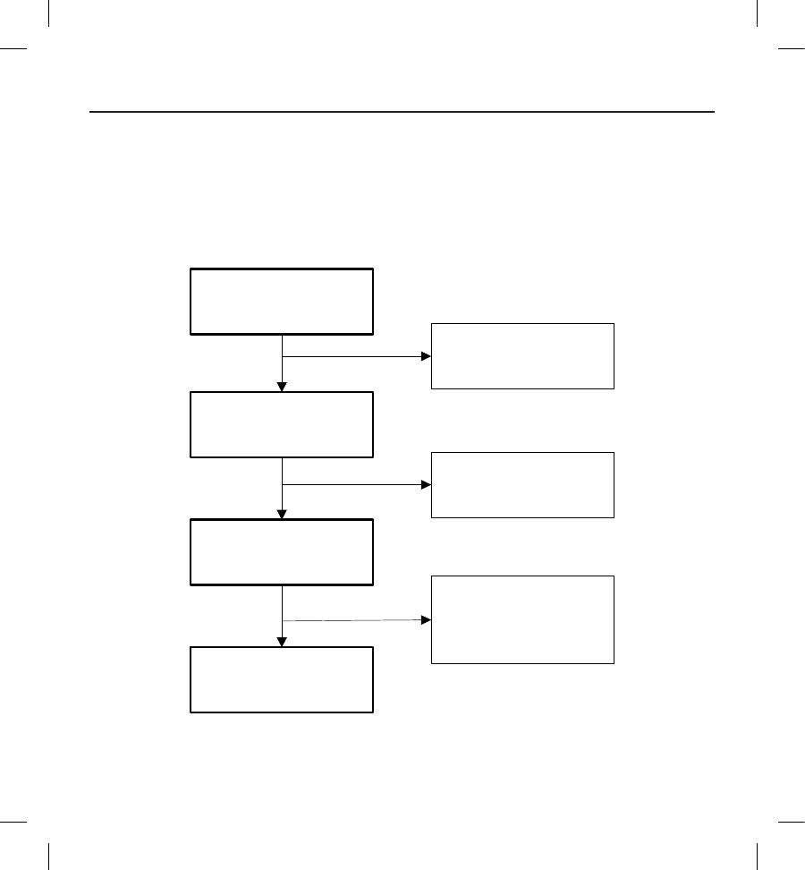
Accountability of PMA Cohort
Of 330 patients enrolled in PMA study, 321 underwent an implant procedure, of whom 314 were implanted with the S-ICD
System. There were 293 patients still active at the time of database lock on February 14, 2012. The mean follow-up duration
for all patients implanted was 330 days with a range of 17 to 715 days. Cumulative time of follow-up for all implanted
patients was 3,410 months. The disposition of all study participants is summarized in Figure 1 below:
Figure 1: Summary of Patient Status as of 14 February, 2012
Enrolled
n=330
Implant Attempt
n=321
Withdrawn Prior to
Implant Procedure
n=9
Active
n=293
Discontinued
n=21
(11 Explanted,
2 Withdrawn,
8 Deaths)
Not Implanted
n=7
(All 7 Withdrawn)
Implanted
n=314
18
The primary safety endpoint analysis cohort includes all patients who underwent an implant attempt for the S-ICD System
(N=321). The primary eectiveness endpoint cohort includes all patients undergoing an implant attempt with complete
acute induced VF conversion tests (N=304). A total of 17 patients did not complete acute induced VF conversion testing as
dened in the protocol. Seven of the 17 patients were ultimately not implanted due to diculty converting VF at 65J. Ten of
the 17 patients did not complete the protocol dened testing criteria but were implanted with the S-ICD System. Of these
10 patients, 6 patients experienced diculty inducing VF, 3 patients had diculty converting VF at 65J and 1 patient with a
persistent LV thrombus was not tested.
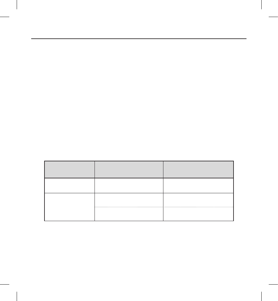
Study Population Demographics and Baseline Parameters
The demographics and baseline characteristics of the study population are shown in Table 1 and Table 2, respectively.
Cardiovascular history included congestive heart failure (61.4%), hypertension (58.3%), and myocardial infarction (41.4%).
All patients met ICD indications as described in Table 3. Primary prevention ICD indications represented 79.4% of the cohort.
Additionally, the study population included patients indicated for implantation due to hypertrophic cardiomyopathy (8.7%),
long-QT syndrome (3.7%), and Brugada syndrome (3.1%).
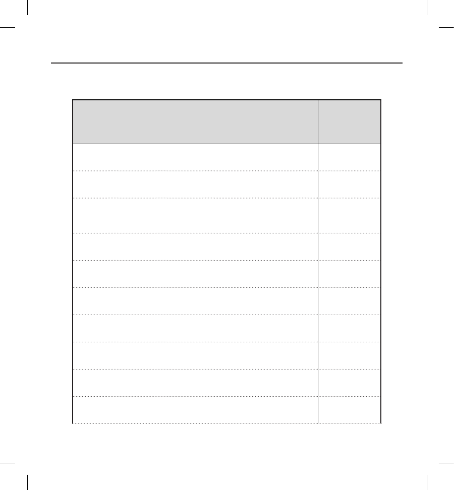
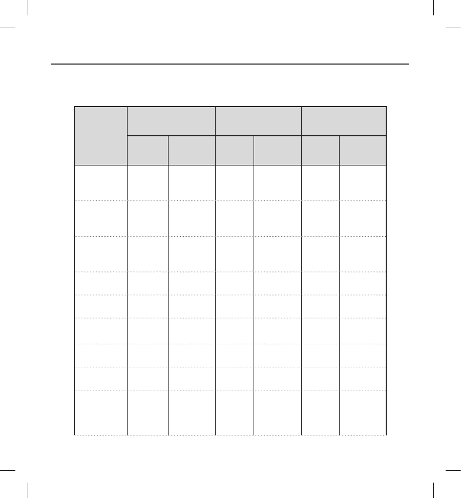
Table 2: Subject demographics
Demographic Statistic/Category N=321
Age (years) Mean ± SD (Median)
Range
51.9 ± 15.5 (53.8 )
18.5-85.2
Gender
(n, %)
Male 238 (74.1)
Female 83 (25.9)
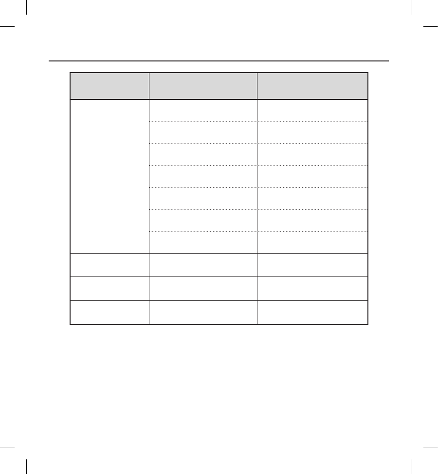
19
Demographic Statistic/Category N=321
Race
(n, %)
White or Caucasian 208 (64.8)
Black or African American 76 (23.7)
Hispanic or Latino 23 (7.2)
Asian 6 (1.9)
Asian Indian 3 (0.9)
Maori 3 (0.9)
Pacic Islander 2 (0.6)
Height (cm) Mean ± SD (Median)
Range
174.3 ± 10.2 (175.0 )
142.2-200.7
Weight (kg) Mean ± SD (Median)
Range
90.5 ± 25.2 (86.6 )
42.6-230.9
BMI Mean ± SD (Median)
Range
29.7 ± 7.2 (29.0 )
15.2-69.0

20
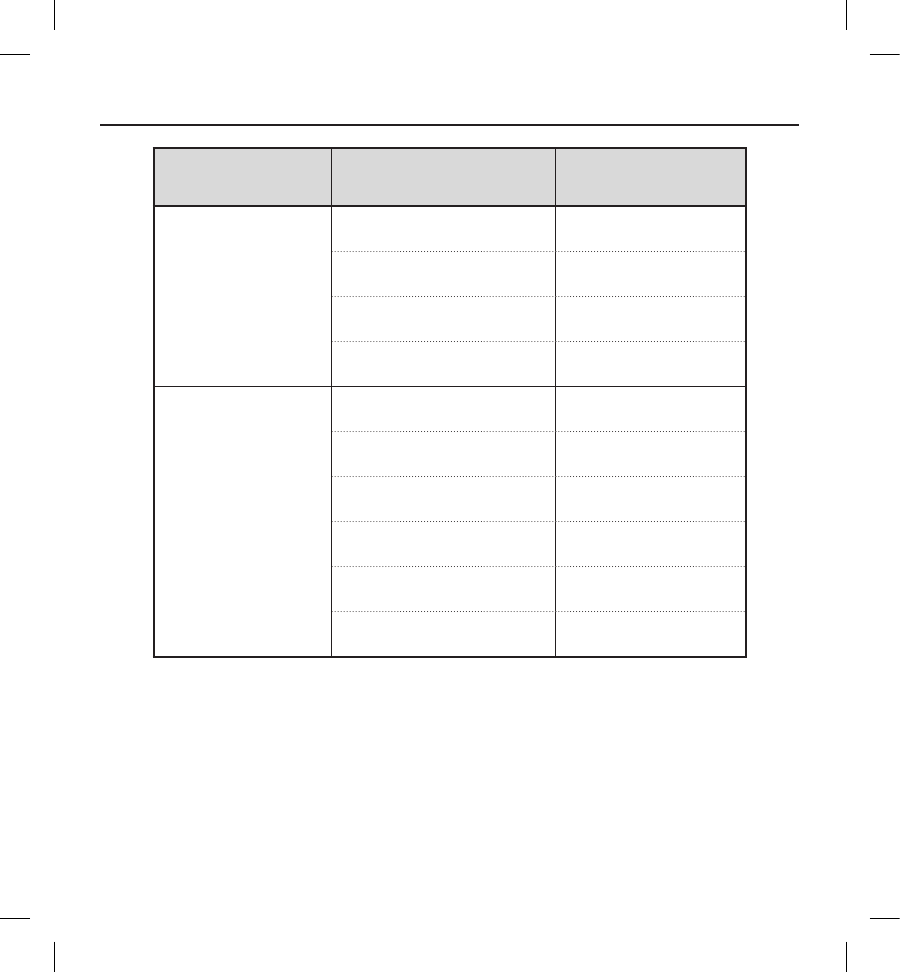
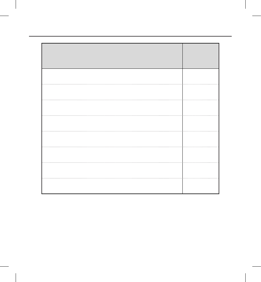
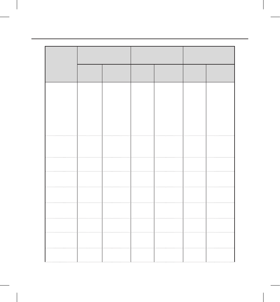
Table 3: Baseline Characteristics
Attribute Statistic/Category N=321
Creatinine
(mg/dL)
Mean ± SD (Median)
Range
1.1 ± 0.4 (1.0 )
0.3-3.7
Ejection
Fraction (%)
(n=299)
Mean ± SD (Median)
Range
36.1 ± 15.9 (31.0 )
10.0-82.0
NYHA
Classication
at Enrollment
(n, %)
I: No Physical Limitations 68 (21.2)
II: Slight Physical Limitations 146 (45.5)
III: Marked Physical Limitations 55 (17.1)
IV: Total Physical Limitations 1 (0.3)
Unknown/Not Assessed 51 (15.9)
Co-morbidities
History
(n, %)
Atrial Fibrillation 49 (15.3)
COPD 27 (8.4)
Cancer 31 (9.7)
Congestive Heart Failure 197 (61.4)
Diabetes 90 (28.0)
21
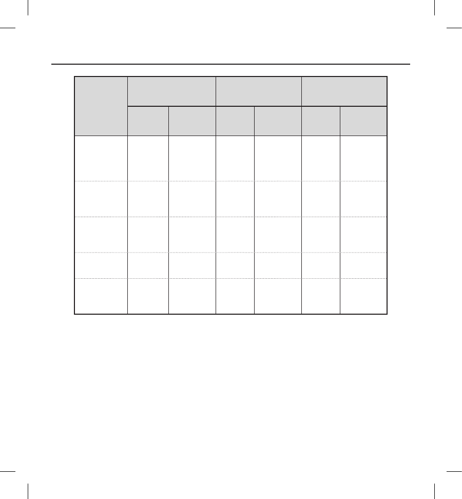
Attribute Statistic/Category N=321
Co-morbidities
History
(n, %)
Hypertension 187 (58.3)
Myocardial Infarction 133 (41.4)
Stroke 18 (5.6)
Valve Disease 42 (13.1)
Cardiac Surgical
History
(n, %)
Ablation 16 (5.0)
CABG 48 (15.0)
Debrillator 43 (13.4)
Pacemaker 4 (1.2)
Percutaneous Revascularization 92 (28.7)
Valve Surgery 18 (5.6)
22
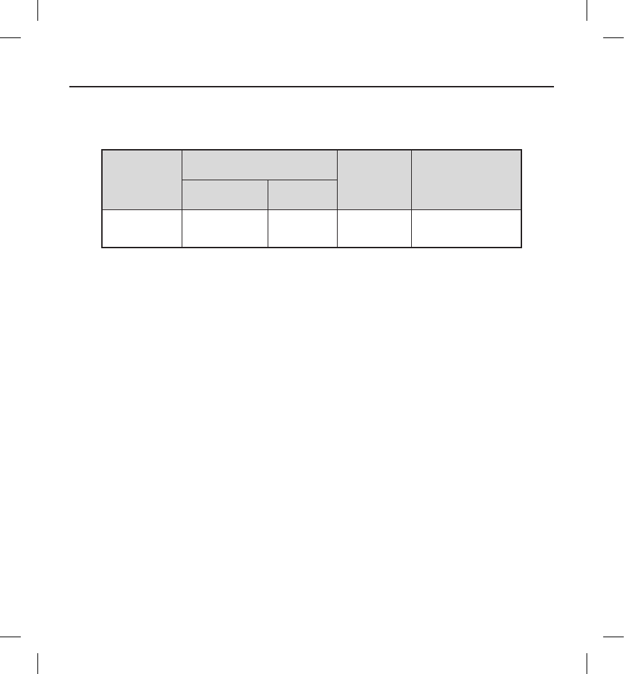
Table 4: Indications According to ACC/AHA/HRS Guidelines
Indication Details
N=321
Patients
n (%)
Left ventricular ejection fraction (LVEF) less than 35% due to prior MI who are at least
40 days post-MI and are in NYHA functional Class II or III 88 (27.4)
Non-ischemic DCM and an LVEF less than or equal to 35% and is in NYHA functional
Class II or III 76 (23.7)
Survivor of cardiac arrest due to VF or hemodynamically unstable sustained VT after
evaluation to dene the cause of the event and to exclude any completely reversible
causes
40 (12.5)
Hypertrophic Cardiomyopathy with risk for SCD 28 (8.7)
Structural heart disease and spontaneous sustained VT, whether hemodynamically
stable or unstable 15 (4.7)
Left Ventricular (LV) dysfunction due to prior MI and is at least 40 days post-MI, has
an LVEF less than 30%, and is in NYHA functional Class I 13 (4.0)
Cardiomyopathy with risk for SCD 13 (4.0)
Long-QT syndrome with risk of SCD 12 (3.7)
Brugada syndrome with risk for SCD 10 (3.1)
Syncope of undetermined origin with clinically relevant, hemodynamically signicant
sustained VT or VF induced at electrophysiological study 7 (2.2)
23
Indication Details
N=321
Patients
n (%)
Familial cardiomyopathy associated with SCD 6 (1.9)
Cardiac sarcoidosis or Chagas disease 4 (1.2)
Arrhythmogenic Right Ventricular Dysplasia/Cardiomyopathy (ARVD/C) with risk for
SCD 3 (0.9)
Nonsustained VT due to prior MI, LVEF less than 40%, and inducible VF or sustained
VT at electrophysiological study 2 (0.6)
LV noncompaction 1 (0.3)
Catecholaminergic polymorphic VT 1 (0.3)
Sustained VT and normal or near-normal ventricular function 1 (0.3)
Symptomatic ventricular arrhythmia 1 (0.3)
24
Safety and Eectiveness Results
Safety Results
The 180-day Type I complication-free rate was assessed in all patients with an attempted S-ICD System implant (N=321) for
the primary safety endpoint. A Type I complication was dened as any clinical event caused by the S-ICD System that required
invasive intervention.
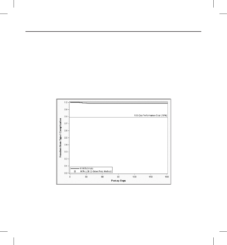
The Type I complication-free rate at 180 days was 99.0% with a lower 95% condence bound of 97.9%. These results meet
the primary safety endpoint performance goal of 79% and demonstrate the safety of the S-ICD System. Details of the Kaplan-
Meier analysis are shown in Figure 2 and Table 5.
Figure 2: Primary Safety Endpoint Kaplan-Meier Analysis
25
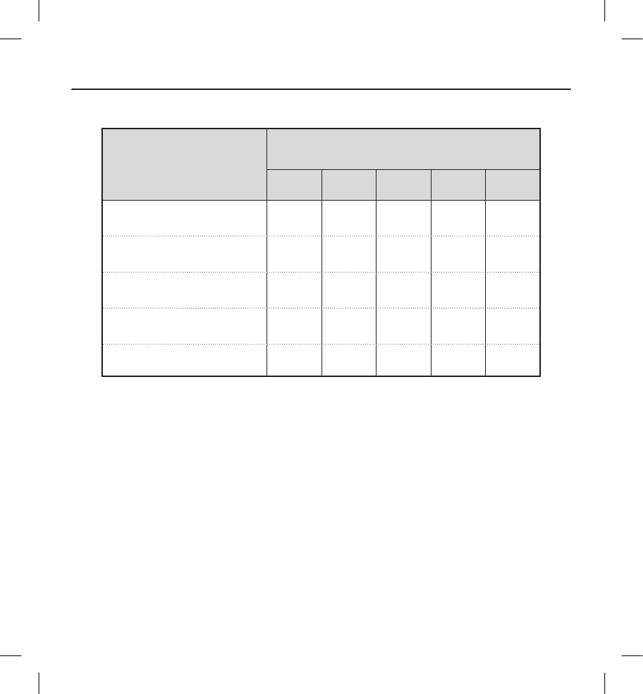
Table 5: Kaplan-Meier Estimates for Primary Safety Endpoint
Statistic
Start of Interval
(Days from Implant)
0 30 90 180 360
Number Remaining at Risk 319 311 308 274 119
Cumulative Patients Censored 2 8 10 44 194
Cumulative Patients with Events 02338
KM Estimate of Patients Free from
Event (%) 100 99.4 99.0 99.0 96.6
95% Lower Condence Bound 100 98.5 98.0 97.9 93.5
Clinical Events
A Clinical Event is dened as any untoward medical occurrence in a patient. An Observation is a clinical event that does not
result in invasive intervention and a Complication is a clinical event that results in invasive intervention. All clinical events
were classied by type based on the cause of the clinical event, according to the following denitions:
• Type I: Caused by the S-ICD System
• Type II: Caused by the S-ICD System user’s manual or labeling of the S-ICD System
• Type III: Not caused by the S-ICD System, but would not have occurred in the absence of the implanted
S-ICD System
• Type IV: Caused by a change in the patient’s condition
Table 6 summarizes all 211 clinical events reported from 139 patients, followed by a full listing of all Type I, II and III clinical
events in Table 7, Table 8 and Table 9, respectively.

26
Table 6: Clinical Event Summary by Type and Observation/Complication
All patients with an implant attempt (N=321)
Clinical
Event
Complications Observations Total
Events Patients (%) Events Patients (%) Events Patients (%)
Type I 12a11 (3.4) 35 30 (9.3) 47 3 (12.1)
Type II 44 (1.2) 00 (0.0) 44 (1.2)
Type III 25 24 (7.5) 83 71 (22.1) 108 88 (27.4)
Type IV 16 15 (4.7) 36 33 (10.3) 52 44 (13.7)
All
Clinical
Events
57 48 (15.0) 154 116
(36.1) 211 139
(43.3)
a Of note, there were a total of 12 Type I Complications throughout the entire follow-up duration. Three (3) occurred within
180 days of implant and are shown in the primary safety Kaplan-Meier analysis (Figure 2). Five (5) additional Type I
complications were observed within 360 days of implant and the remaining four (4) occurred after 360 days post-implant.

27
Table 7: Type I Clinical Events
All patients with an implant attempt (N=321)
Clinical
Event
Complications Observations Total
Events Patients (%) Events Patients (%) Events Patients (%)
Discomfort 3 3 (0.9) 87 (2.2) 11 11 (3.4)
Inability to
Communicate
with the Device
22 (0.6) 00 (0.0) 22 (0.6)
Inappropriate
Shock:
Oversensing
55 (1.6) 25 21 (6.5) 30 25 (7.8)
Numbness at
Device Site 00 (0.0) 11 (0.3) 11 (0.3)
Premature
Battery
Depletion
22 (0.6) 00 (0.0) 22 (0.6)
Subcutaneous
Emphysema 00 (0.0) 11 (0.3) 11 (0.3)
All Type
I Clinical
Events
12 11 (3.4) 35 30 (9.3) 47 39 (12.1)

28
Table 8: Type II Clinical Events
All patients with an implant attempt (N=321)
Clinical
Event
Complications Observations Total
Events Patients (%) Events Patients (%) Events Patients (%)
Electrode
Movement 22 (0.6) 00 (0.0) 22 (0.6)
Inappropriate
Electrode
Connection to
the Device
11 (0.3) 00 (0.0) 11 (0.3)
Sub-optimal
Electrode
Position
11 (0.3) 00 (0.0) 11 (0.3)
All Type
II Clinical
Events
44 (1.2) 00 (0.0) 44 (1.2)
29
Table 9: Type III Clinical Events
All patients with an implant attempt (N=321)
Clinical
Event
Complications Observations Total
Events Patients (%) Events Patients (%) Events Patients (%)
Acute Hypoxic
Respiratory
Failure
00 (0.0) 11 (0.3) 11 (0.3)
Adverse
Reaction to
Medication
33 (0.9) 55 (1.6) 88 (2.5)
Atrial
Fibrillation /
Flutter
00 (0.0) 14 14 (4.4) 14 14 (4.4)
Bleeding 0 0 (0.0) 11 (0.3) 11 (0.3)
Discomfort 1 1 (0.3) 12 12 (3.7) 13 12 (3.7)
Electrode
Movement 11 (0.3) 00 (0.0) 11 (0.3)
Fever 0 0 (0.0) 33 (0.9) 33 (0.9)
Hematoma 1 1 (0.3) 54 (1.2) 65 (1.6)
Inadequate/
Prolonged
Healing of
Incision Site
33 (0.9) 22 (0.6) 55 (1.6)
30
Clinical
Event
Complications Observations Total
Events Patients (%) Events Patients (%) Events Patients (%)
Inappropriate
Shock: SVT
Above Discrim
ination Zone
(Normal Device
Function)
44 (1.2) 17 14 (4.4) 21 16 (5.0)
Incision/
Supercial
Infection
11 (0.3) 13 13 (4.0) 14 14 (4.4)
Keloid 1 1 (0.3) 00 (0.0) 11 (0.3)
Local Tissue
Reaction 00 (0.0) 11 (0.3) 11 (0.3)
Numbness at
Device Site 00 (0.0) 11 (0.3) 11 (0.3)
PG Movement/
Revision 11 (0.3) 00 (0.0) 11 (0.3)
Phantom Shock 00 (0.0) 53 (0.9) 53 (0.9)
Redness/
Irritation 00 (0.0) 22 (0.6) 22 (0.6)
Stroke 0 0 (0.0) 11 (0.3) 11 (0.3)
31
Clinical
Event
Complications Observations Total
Events Patients (%) Events Patients (%) Events Patients (%)
Sub-optimal
PG and
Electrode
Position
33 (0.9) 00 (0.0) 33 (0.9)
Sub-optimal
Pulse Generator
Position
11 (0.3) 00 (0.0) 11 (0.3)
Suspected
Worsening of
Ischemia
11 (0.3) 00 (0.0) 11 (0.3)
System
Infection 44 (1.2) 00 (0.0) 44 (1.2)
All Type
III Clinical
Events
25 24 (7.5) 83 71 (22.1) 108 88 (27.4)

32
Device Explants
Eleven (11) patients exited the study after the S-ICD System was removed for: system infection (4), oversensing (2), pre-
mature battery depletion (1), transvenous device implanted to provide overdrive pacing for ventricular arrhythmia trigger
suppression (1), elective explant due to the development of an indication for biventricular pacing (1), elective explant due to
development of high debrillation threshold (1), and elective due to patient request (1).
Patient Deaths
Eight (8) deaths occurred in the study. None of the deaths were conclusively identied to be associated with the device or
procedure.
Eectiveness Results
The eectiveness of the S-ICD System was assessed by the proportion of patients with successful acute (induced) VF conversion
in all patients with an attempted S-ICD System implant (N=320).2 A successful VF conversion test required two consecutive VF
conversions at 65 J from four induction attempts within a given shock polarity.
Of the 320 patients who underwent acute VF conversion testing, 16 patients3 yielded non-evaluable results due to incomplete
protocol testing. Of the 304 evaluable results, the S-ICD System acute VF conversion success rate was 100% with a lower
95% condence bound of 98.8% (Table 9). These results met the primary safety endpoint performance goal of 88% and
demonstrate the eectiveness of the S-ICD System.
2 One (1) patient did not undergo testing at the discretion of the investigator.
3 Nine (9) patients were implanted with the S-ICD System. Seven (7) patients with non-evaluable tests were not implanted. Five (5) of the
seven (7) patients received a transvenous ICD and information regarding subsequent device implantation for two (2) patients is unknown.
33
Table 10: Eectiveness Endpoint Result - Acute VF Conversion Rate
Patients undergoing acute VF conversion testing (N=320)
Non-
evaluable
Results
Evaluable Results Estimate
(%)
95% Clopper-
Pearson Interval
(%)
Successful Failure
16 304 0 100.0 (98.8-100.0)
Of the 16 non-evaluable patients, 11 were associated with at least one failed conversion attempt at 65 J and, due to physician
discretion, did not exhaust all of the protocol dened induction attempts in both shock polarities. A sensitivity analysis was
performed to impute these patients as failures despite incomplete testing, resulting in an imputed VF conversion success rate
of 96.5%.
Spontaneous Episodes
A total of 119 spontaneous VT/VF episodes in 21 patients were treated by the S-ICD System through February 14, 2012. A
VT/VF episode refers to a device-declared episode in which device rate/discrimination criteria were met in response to a
ventricular tachyarrhythmia and therapy was delivered. A single episode may contain up to 5 shocks. The episode ends when
the rolling average of the rate falls below the lowest programmed rate zone for 24 consecutive intervals.
For analysis, episodes were sub-divided into two classes: 1) discrete episodes that were temporally independent (<3 within 24
hours); and, 2) VT/VF storms that comprise 3 or more treated VT/VF episodes within 24 hours in the same patient. Of the 38
discrete device episodes, 35 (92.1%) were converted with the rst shock and 37 (97.4%) were converted by any shock (Table
10). One episode terminated spontaneously after an unsuccessful rst shock (MVT). Four (4) VT/VF storms from 2 patients
resulted in 81 total device episodes, 40 of which were VF and stored in S-ICD System memory with the remaining 41 episodes
not stored due to memory capacity limitations. Three (3) storms were ultimately converted by the S-ICD System and 1 was
ultimately converted with an external debrillation shock (Table 11). Of the 40 storm episodes with recorded data (53 total
shocks), successful conversion following at least one shock from either shock polarity (shock 1 & 2) was 92.5%.
34
Table 11: Conversion Eectiveness of Discrete Device Episodes (non-Storm)
Patients with discrete episodes (N=21); Discrete device episodes (N=38)
Rhythm Patients Device
Episodes
Episode
Converted by
1st Shock (%)
Episode
Converted by
Any Shock(%)
MVT 13 22 21 (95.5) 21 (95.5)
PVT/VF 11 16 14 (87.5) 16 (100.0)
Total 21 38 35 (92.1) 37 (97.4)
Table 12: Conversion of VT/VF Storms
Patients with VT/VF Storms (N=2), Storm events (N=4), Stored Device episodes (N=40)
Patients VT/VF
Storms
Device
Episodes
Final Storm
Conversion Method (%)
2 4 40
S-ICD: 3 (75)
External: 1 (25)
Spontaneous Conversion: 0 (0)
Chronic Conversion Substudy
The chronic performance of the S-ICD System was assessed by the proportion of patients with successful conversion of induced
VT/VF ≥150 days post-implant in all implanted patients who provided informed consent for this testing (N=78). Three (3)
patients were excluded from the analysis because they met the pre-specied denition of a non-evaluable test (did not
complete testing in the opposite polarity after a failed 65J shock, as required by the protocol). All three were converted with a
subsequent 80J S-ICD System shock.

35
The rate of successful conversion by a sub-maximal (65J) S-ICD System shock was 72/75 (96.0%). All 3/75 (4.0%) patients
who failed to convert with a sub-maximal (65J) S-ICD System shock in either polarity were successfully converted with a
subsequent higher-energy S-ICD System shock.
Subgroup Analyses
Stepwise logistic regression models (backward elimination with a threshold p-value of 0.20) were used to evaluate basic
demographic characteristics (age, gender, African American race) and baseline device programming (dual zone programming
at hospital discharge) for statistical associations between with following safety-related outcomes:
• All Inappropriate shocks (n=41)
• Inappropriate shocks for oversensing (n=25)
• Inappropriate shocks for SVT (n=16)
• Discomfort (n=22)
• System and Supercial/Incision Infection (n=18)
• Type I-III Complications (n=35)
Age
Age was a signicant predictor for inappropriate shocks. Patients who experienced inappropriate shocks were younger with a
mean age of 47 compared to a mean age of 53 for patients who did not receive any inappropriate shocks.
Gender
Female gender was signicantly associated with a higher risk for device or procedure related discomfort. Although the
numbers are very small, it is notable that the inframammary crease was cited in 2 cases of female discomfort and the interface
between the device site and the patient’s bra was cited in another case.
Race
African American race was not associated with device or procedure related complications.
Dual Zone Programming at Discharge
Dual zone programming at the time of hospital discharge was associated with signicantly fewer inappropriate shocks than
those programmed with a single zone. There was a 70% relative reduction of incidence for inappropriate shocks due to
SVT and a 56% relative reduction of incidence for inappropriate shocks due to oversensing, when compared to single zone
programming.

36
Conclusion
The purpose of the S-ICD System Clinical Investigation was to evaluate the safety, eectiveness and chronic performance of
the S-ICD System. There were 330 patients enrolled in the study and 321 underwent an implant procedure. The 314 patients
implanted with the S-ICD System generated 3,410 months of patient data.
The data demonstrate that the S-ICD System operates appropriately per design for the S-ICD System’s intended uses and as
described in the S-ICD System’s labeling. All objectives of the S-ICD System Clinical Investigation were met demonstrating
safety and eectiveness of the S-ICD System.
37
Patient Screening
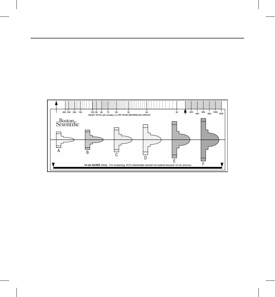
The patient screening tool, Model 4744 (Figure 3) is a customized measurement tool made of transparent plastic printed with
colored proles. The proles are designed to ensure appropriate device performance by identifying signal characteristics that
may lead to unsatisfactory detection outcomes for a patient before implant. The patient screening process is completed in
three steps: (1) Collecting the surface ECG, (2) Evaluating the surface ECG and (3) Determining an acceptable sense vector.
The patient screening tool can be obtained from any Boston Scientic representative or by contacting Boston Scientic using
the information on the back cover.
Figure 3: Patient Screening Tool. Each colored prole is assigned a letter (A,B,C,D,E,F) for ease of reference.
Collecting the Surface ECG
1. In order to perform the patient screening process, a surface equivalent of the subcutaneous sensing vectors must
be obtained. It is important to collect the surface ECG in the location that represents the intended position of the
implanted S-ICD System. When placing the S-ICD System in the typical implant location, the surface ECG electrode
should be positioned as described below (Figure 4). If a non-standard S-ICD System subcutaneous electrode or pulse
generator placement is desired, the surface ECG electrode locations should be modied accordingly.
• ECG Electrode LL should be placed in a lateral location, at the 5th intercostal space along the mid-
axillary line to represent the intended location of the implanted pulse generator.
• ECG Electrode LA should be placed 1 cm left lateral of the xiphoid midline to represent the intended
location of the proximal sensing node of the implanted subcutaneous electrode.
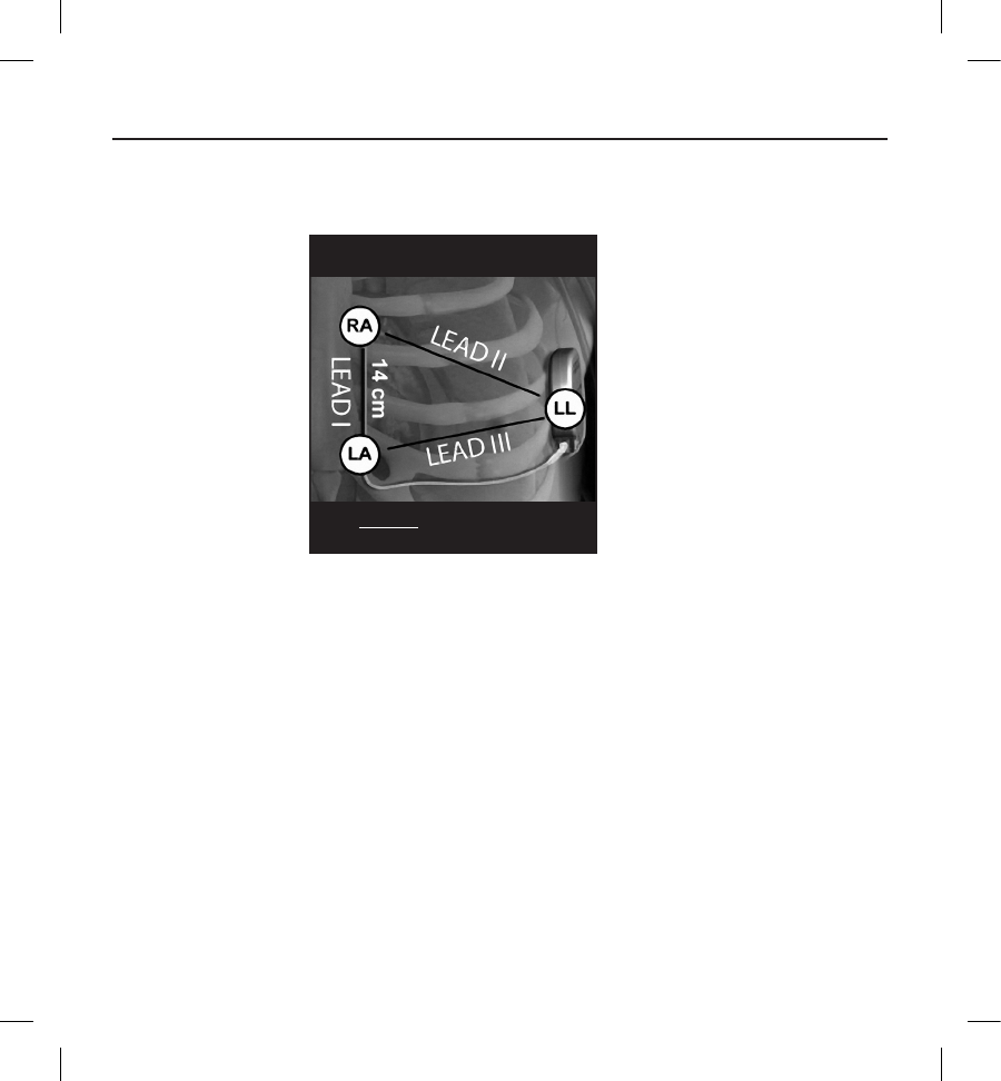
38
• ECG Electrode RA should be placed 14 cm superior to the ECG Electrode LA, to represent the intended
position of the distal sensing tip of the implanted subcutaneous electrode. A 14 cm guide is located at
the bottom of the transparent screening tool.
Figure 4:
1. RECORD Supine + Standing
25 mm/s, 5-20 mm/mV
SIMULTANEOUS 3-LEAD ECG
Typical placement of surface ECG electrodes for patient screening
2. Using a standard ECG machine, record 10 - 20 seconds of ECG using Leads I, II and III with a sweep speed of 25 mm/
sec and ECG gain between 5 - 20 mm/mV (use the largest ECG gain that does not result in clipping).
Note: It is important to establish a stable baseline when collecting the surface ECG. If a wandering baseline is noted,
ensure that the appropriate ground electrodes from the ECG machine are attached to the patient. To yield an acceptable
signal for testing, the gain may be adjusted for each ECG lead independently.
3. Record ECG signals in at least two postures: (1) Supine and (2) Standing. Other postures may be collected including:
Seated, Left Lateral, Right Lateral, and Prone.
Note: If the S-ICD System is to be implanted with a concomitant pacemaker, all ventricular morphologies
(paced and intrinsic, if normal conduction is expected) should be collected.
Evaluating the Surface ECG
Each surface ECG should be evaluated by analyzing at least 10 seconds of QRS complexes. If multiple morphologies are noted
(e.g., bigeminy, pacing, etc.), all morphologies should be tested as described below before the vector is deemed acceptable.
39
Each QRS complex is evaluated as follows:
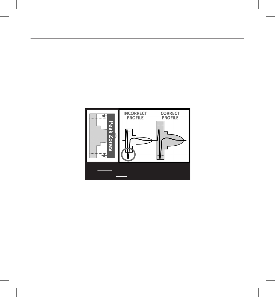
1. Select the colored prole from the Patient Screening Tool that best matches the amplitude of the QRS (Figure 5). For
biphasic signals, the larger peak should be used to determine the appropriate colored prole. The QRS peak must fall
within the window bounded by the dotted line and the peak of the colored prole.
Note: ECG gains > 20 mm/mV are not permitted. If, when printed at the maximum 20 mm/mV gain, the QRS
peak does not reach the minimum boundary (dotted line) of the smallest colored prole, that QRS complex is
deemed unacceptable.
Figure 5:
2. SELECT the colored prole. The largest
QRS peak must be within a Peak Zone.
Selecting the colored prole
2. Align the left edge of the selected colored prole with the onset of the QRS complex. The horizontal line on the
colored prole should be used as a guide for isoelectric baseline alignment.
40
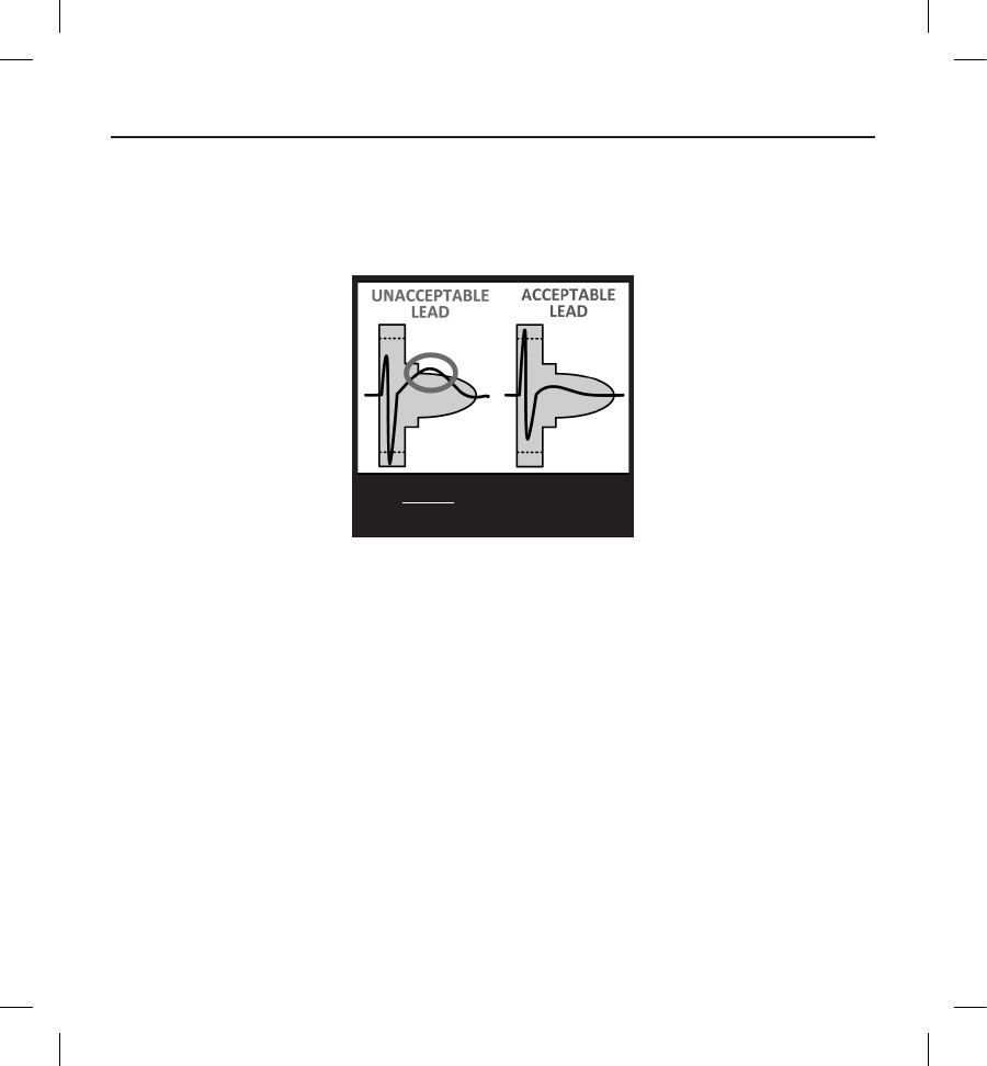
3. Evaluate the QRS complex. If the entire QRS complex and trailing T-wave are contained within the colored prole,
the QRS is deemed acceptable. If any portion of the QRS complex or trailing T-wave extends outside of the colored
prole, the QRS is deemed unacceptable (Figure 6).
Figure 6:
3. VERIFY at least one lead is
acceptable in all postures.
Evaluating the QRS complex
4. Repeat the above steps with all QRS complexes collected with all surface ECG leads in all collected postures.
Determining an Acceptable Sense Vector
Each collected surface ECG lead represents a sense vector of the S-ICD System. Evaluate each surface ECG lead independently
for acceptability. A surface ECG lead (sense vector) should be deemed acceptable only if all of the following conditions are met:
• All tested QRS complexes and morphologies from the surface ECG lead (sense vector) must pass the
QRS evaluation. Exceptions can be made for a large morphology change associated with an occasional
ectopic beat (e.g. PVC).
• The morphology of the intrinsic/paced QRS complex is stable across postures. No signicant change to
the QRS complex is noted as a result of postural changes.
• The surface ECG lead (sense vector) must be deemed acceptable in all tested postures.
A patient is considered suitable for implant of the S-ICD System if at least one surface ECG lead (sense vector) is acceptable for
all tested postures.

41
Note: Special circumstances may present in which the physician elects to proceed with the implantation of the
S-ICD System despite failing the screening process. In this case, careful attention should be applied to the device
setup process of the S-ICD System as the risk of poor sensing and/or inappropriate shock is increased.
Operation
General
The S-ICD System is designed for ease of use and simplicity of patient management. The arrhythmia detection system
employs up to two rate zones, and the device has a single automatic response to a detected ventricular tachyarrhythmia – a
nonprogrammable, maximum-energy, biphasic shock of 80 J. The device has a number of automatic functions designed to
reduce the amount of time required for implantation, initial programming and patient follow-up.
Modes of Operation
The device has three modes of operation:
• Shelf
• Therapy On
• Therapy O
Shelf Mode
The Shelf mode is a low power consumption state intended for storage only. When communication is initiated
between the device and the programmer, a full-energy capacitor reformation is performed and the device is
prepared for setup. Once the device is taken out of Shelf mode, it cannot be reprogrammed back into Shelf
mode.
Therapy On Mode
The Therapy On mode is the primary operating mode of the device, allowing automatic detection of and
response to ventricular tachyarrhythmias. All device features are active.
Note: The device must be programmed out of Shelf mode before being programmed to Therapy On.
Therapy O Mode
The Therapy O mode disables automatic therapy delivery while still allowing manual control of shock delivery.
Programmable parameters may be viewed and adjusted via the programmer. Also, the subcutaneous electrogram (S-ECG) may
be displayed or printed.

42
The device automatically defaults to Therapy O when taken out of Shelf mode.
Note: Manual and rescue shock therapy are available when the device is set to Therapy On or Therapy
Off mode, but only after the initial Setup process is complete. Refer to Setting up the EMBLEM S-ICD Pulse
Generator on page 65.
Sensing Conguration and Gain Selection
During the Automatic Setup process, the device automatically selects an optimal sensing vector based on an analysis of
cardiac signal amplitude and signal-to-noise ratio. This analysis is performed on the three available vectors:
• Primary: Sensing from the proximal electrode ring on the subcutaneous electrode to the active surface
of the device.
• Secondary: Sensing from the distal sensing electrode ring on the subcutaneous electrode to the active
surface of the device.
• Alternate: Sensing from the distal sensing electrode ring to the proximal sensing electrode ring on the
subcutaneous electrode.
The sensing vector can also be selected manually. The EMBLEM S-ICD Programmer User’s Manual provides additional
information about sensing vector selection.
The device automatically selects an appropriate gain setting during the Automatic Setup process. The gain can also be
manually selected, as further explained in the EMBLEM S-ICD Programmer User’s Manual. There are two gain settings:
• 1x Gain (±4 mV): Selected when the signal amplitude is clipped at the 2x gain setting.
• 2x Gain (±2 mV): Selected when the signal amplitude is not clipped at this setting.
Sensing and Tachyarrhythmia Detection
The device is designed to prevent inappropriate therapy delivery as a result of noise sensing or multiple counting of individual
cardiac cycles. This is accomplished by an automatic analysis of sensed signals, which includes event detection, certication
and decision phases.
Detection Phase
During the Detection Phase, the device uses a detection threshold to identify sensed events. The detection threshold is
automatically adjusted continuously using amplitudes of recently detected electrical events. In addition, detection parameters
are modied to increase sensitivity when rapid rates are detected. Events detected during the Detection Phase are passed on
to the Certication Phase.
43
Certication Phase
The Certication Phase examines the detections and classies them as certied cardiac events or as suspect events. Certied
events are used to ensure that an accurate heart rate is passed to the Decision Phase. A suspect event can be one whose
pattern and/or timing indicates the signal is caused by noise, such as a muscle artifact or some other extraneous signal. Events
are also marked as suspect if they appear to derive from double or triple detections of single cardiac events. The device is
designed to identify and correct multiple detections of wide QRS complexes and/or erroneous detections of a T-wave.
Decision Phase
The Decision Phase examines all certied events and continuously calculates a running four R-to-R interval average (4 RR
average). The 4 RR average is used throughout the analysis as an indicator of the heart rate.
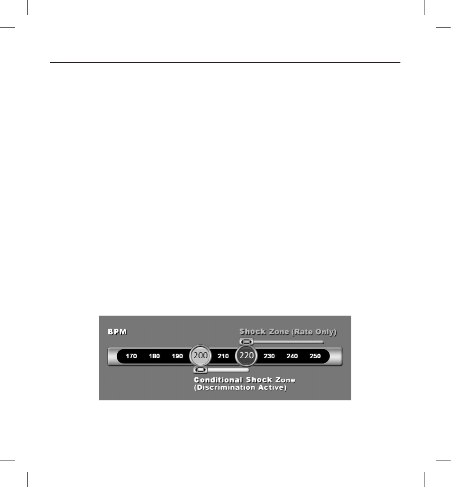
Therapy Zones
The device allows the selection of rate thresholds that dene a Shock Zone and an optional Conditional Shock Zone. In the
Shock Zone, rate is the only criterion used to determine if a rhythm will be treated with a shock. The Conditional Shock Zone
has additional discriminators used to determine if a shock is warranted to treat an arrhythmia.
The Shock Zone is programmable from 170 – 250 bpm in increments of 10 bpm. The Conditional Shock Zone must be lower
than the Shock Zone, with a range of 170 - 240 bpm in increments of 10 bpm.
Note: To ensure proper detection of VF, program the Shock Zone or Conditional Shock Zone to 200 bpm or less.
Note: The IDE Study demonstrated a signicant reduction in inappropriate therapy with the activation of the
Conditional Shock Zone prior to hospital discharge (see S-ICD System Clinical Investigation, page 15).
Graphically, the use of a Shock Zone and Conditional Shock Zone is shown below (Figure 7):
Figure 7: Shock Zone Rate Detection Diagram
44
The device declares a Tachycardia when the 4RR average enters either therapy zone.
Once a Tachycardia is declared, the 4RR average must become longer (in ms) than the lowest rate zone plus 40 ms for 24
cycles for the device to consider the episode to have ended. In the Shock Zone, treatable arrhythmias are determined by rate
alone.
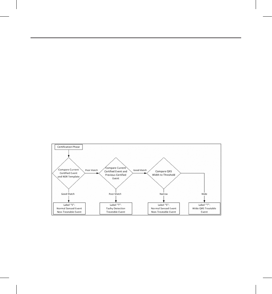
Analysis in the Conditional Shock Zone
In contrast, rate and morphology are analyzed in the Conditional Shock Zone. The Conditional Shock Zone is designed
to discriminate between treatable and other high-rate events such as atrial brillation, sinus tachycardia and other
supraventricular tachycardias.
A normal sinus rhythm template (NSR Template) is formed during device initialization. This NSR template is used during
analysis in the Conditional Shock Zone to identify treatable arrhythmias. In addition to morphology comparison with the NSR
template, other morphologic analysis is used to identify polymorphic rhythms. Morphology and QRS width are used to identify
monomorphic arrhythmias such as ventricular tachycardia. If the Conditional Shock Zone is enabled, then an arrhythmia is
found to be treatable according to the decision tree shown below (Figure 8).
Figure 8: Decision tree for determining treatable arrhythmias in the Conditional Shock Zone
For some patients, a NSR Template may not be formed during device initialization as a result of variability in their cardiac
signal at resting heart rates. For such patients, the device uses beat-to-beat morphology and QRS width analysis for
arrhythmia discrimination.

45
Charge Conrmation
The device must charge the internal capacitors before shock delivery. Conrmation of the ongoing presence of a
tachyarrhythmia requires monitoring a moving window of the 24 most recent intervals dened by certied events. Charge
conrmation employs an X (treatable interval) out of Y (total intervals in the window) strategy to accomplish this. If 18 of
the 24 most recent intervals are found to be treatable, the device begins to analyze rhythm persistence. Persistence analysis
requires the X out of Y condition be maintained or exceeded for at least two consecutive intervals; however, this value may be
increased as a result of Smart Charge, as explained below.
Capacitor charging is initiated when the following three conditions are met:
1. X of Y criterion is satised
2. Persistence requirement is satised
3. The last two certied intervals are in the treatable zone.
Therapy Delivery
Rhythm analysis continues throughout the capacitor charging process. Therapy delivery is aborted if the 4 RR average interval
becomes longer (in ms) than the lowest rate zone plus 40 ms for 24 intervals. When this occurs, an untreated episode is
declared and a Smart Charge extension is incremented, as explained below.
Capacitor charging continues until the capacitor has reached its target voltage, at which time reconrmation is performed.
Reconrmation is used to ensure that the treatable rhythm did not spontaneously terminate during the charging cycle.
Reconrmation requires the last three consecutive detected intervals (regardless of whether the intervals are certied or
suspect) to be faster than the lowest therapy zone. If non-treatable events are detected during or after the charging sequence,
reconrmation is automatically extended, one interval at a time, up to a maximum of 24 intervals.
Reconrmation is always performed and shock delivery is non-committed until reconrmation is complete. Once the criteria
for reconrmation are met, the shock is delivered.
Smart Charge
Smart Charge is a feature that automatically increases the Persistence requirement by three intervals each time an untreated
episode is declared, up to a maximum of ve extensions. Thus, after an untreated episode, the requirement to start capacitor
charging becomes more stringent. The Smart Charge extension value can be reset to its nominal value (zero extensions) using
the programmer. The Smart Charge feature cannot be disabled, though it is not used for the second and later shocks that
occur during any given episode.

46
Redetection
A blanking period is enabled following delivery of a high-voltage shock. After delivery of the rst shock, up to four additional
shocks will be delivered if the episode does not terminate. Rhythm analysis for delivering shocks 2 - 5 generally follows the
detection steps described above, with the following exceptions:
1. Following the rst shock delivery, the X/Y criterion is modied to require 14 treatable intervals in the last 24 (14/24),
rather than 18.
2. The Persistence Factor is always set to two intervals (i.e., not modied by the Smart Charge feature).
Shock Waveform and Polarity
The shock waveform is biphasic, with a xed tilt of 50%. The shock is delivered synchronously unless a 1000 ms time out
expires without an event being detected for synchronization, at which time the shock is delivered in an asynchronous manner.
The device is designed to automatically select the appropriate polarity for therapy. Both standard and reversed polarity shocks
are available. If a shock fails to convert the arrhythmia and subsequent shocks are required, polarity is automatically reversed
for each successive shock. The polarity of the successful shock is then retained as the starting polarity for future episodes.
Polarity can also be selected during the Induction and Manual Shock process to facilitate device-based testing.
Post-Shock Bradycardia Pacing Therapy
The device provides optional post-shock, on-demand bradycardia pacing therapy. When enabled via the programmer,
bradycardia pacing occurs at a non- programmable rate of 50 bpm for up to 30 seconds. The pacing output is xed at 200 mA,
and uses a 15 ms biphasic waveform.
Pacing is inhibited if the intrinsic rate is greater than 50 bpm. In addition, post-shock pacing is terminated if a
tachyarrhythmia is detected or a magnet is placed over the device during the post-shock pacing period.
Manual and Rescue Shock Delivery
Upon programmer command, the device can deliver manual and rescue shocks. Manual shocks are programmable from 10 to
80 J delivered energy in 5 J steps. Rescue shocks are non-programmable, delivering the maximum output of 80 J.
Note: A rescue shock that is commanded when the magnet is already in place will be delivered, but if the magnet
is applied after the rescue shock is commanded, the shock will be aborted. Refer to the S-ICD System Magnet Use
section for complete information.
Additional Features of the S-ICD System
This section presents descriptions of several additional features available in the S-ICD System.

47
Auto Capacitor Reformation
The device automatically performs a full-energy (80 J) capacitor reformation when taken out of Shelf mode and every four
months until the device reaches Elective Replacement (ERI). The energy output and reformation time interval are non-
programmable. The Auto Capacitor Reformation interval is reset after any 80 J capacitor charge is delivered or aborted.
Internal Warning System – Beeper Control
The device has an internal warning system (beeper) that emits an audible tone to alert the patient to certain device conditions
that require prompt consultation with the physician. These conditions include:
• Elective Replacement (ERI) and End of Life (EOL) indicators (see page 48)
• Electrode impedance out of range
• Prolonged charge times
• Failed Device Integrity Check
• Irregular battery depletion
This internal warning system is automatically activated at time of implant. Once triggered, the beeper sounds for 16 seconds
every nine hours until the trigger condition has been resolved. If the triggering condition reoccurs, then the tones will once
again alert the patient to consult the physician. The beeper can be disabled via the programmer once ERI is reached.
Caution: Patients should be advised to contact their physician immediately whenever they hear beeping tones
coming from their device.
Note: The beeper may be activated for demonstration purposes in the clinic by applying a magnet over the device
to elicit the beeping tones.
Arrhythmia Induction
The device facilitates testing by providing the capability to induce a ventricular tachyarrhythmia. Via the programmer, the
implanted system can deliver a 200 mA output at a frequency of 50 Hz. The maximum length of stimulation is 10 seconds.
Note: Induction requires that the device be programmed to Therapy On.
Warning: Always have external debrillation equipment and medical personnel skilled in CPR available during
implant and follow-up testing. If not terminated in a timely fashion, an induced ventricular tachyarrhythmia can
result in the patient’s death.
System Diagnostics
The S-ICD System automatically performs a diagnostic check at scheduled intervals.

48
Subcutaneous Electrode Impedance
A subcutaneous electrode integrity test is performed once a week using a sub-threshold energy pulse. The Summary report
indicates whether the measured impedance is in range by reporting "Ok" for values below 400 ohms. Values above 400 ohms
will result in activation of the internal warning system (beeping tones).
Note: If the device is taken out of Shelf mode, but not implanted, the internal warning system will be activated
due to the weekly automatic measurements of impedance. Device beeping due to this mechanism is normal
behavior.
In addition, subcutaneous electrode impedance is measured each time a shock is delivered, and the shock impedance
values are stored and displayed in the episode data and reported on the programmer screen just after the shock is delivered.
Reported shock impedance values should be within 25 – 200 ohms. A reported value of greater than 200 ohms will activate
the internal warning system.
Caution: A reported shock impedance value of less than 25 ohms from a delivered shock could indicate a problem
with the device. The delivered shock may have been compromised, and/or any future therapy from the device may
be compromised. If a reported impedance value of less than 25 ohms is observed, correct functioning of the device
should be veried.
Note: Measurement of electrode impedance either by the sub-threshold measurement or during shock delivery
may not detect a loose setscrew due to the location of the setscrew at the electrode tip.
Device Integrity Check
The Device Integrity Check is automatically performed daily by the implanted system, and also each time the programmer
communicates with an implanted device. This test scans for any unusual conditions in the device and, if any are detected, the
system provides a notication either via the pulse generator’s internal warning system or on the programmer screen.
Battery Performance Monitoring System
The device automatically monitors battery status to provide notice of impending battery depletion. Two indicators are
provided via messages on the programmer, each activated by declining battery voltage. ERI and EOL are also signaled by
activation of the device’s beeper.
• Elective Replacement Indicator (ERI): When the ERI is detected, the device will provide therapy for
at least three months, if no more than six maximum energy charges/shocks occur. The patient should be
scheduled for replacement of the device.
• End of Life (EOL): When the EOL indicator is detected, the device should be replaced immediately.
Therapy may not be available when EOL is declared.

49
Storing and Analyzing Data
The device stores S-ECGs for up to 25 treated and 20 untreated tachyarrhythmia episodes. An episode is only stored
if it progresses to the point where charging is initiated. The number of treated episodes, untreated episodes, and the
therapy shocks delivered since the last follow-up procedure and initial implant are recorded and stored. Through wireless
communication with the programmer, the stored data is retrieved for analysis and report printouts.
Note: Episode data associated with programmer commanded rescue shocks, manual shocks, induction testing
or episodes that occur while communicating with the programmer are not stored by the pulse generator. Episode
data associated with induction testing commanded by the programmer using the Hold to Induce button is
captured by the programmer and is available as a captured S-ECG (see the EMBLEM S-ICD Programmer User’s
Manual for more details).
Note: SVT episodes with heart rates lower than or within the Conditional Shock zone are not stored.
Treated Episodes
Up to 128 seconds of S-ECG data is stored for each treated episode:
• First Shock: 44 seconds prior to capacitor charging, up to 24 seconds prior to shock delivery and up to
12 seconds of post-shock S-ECG.
• Subsequent Shocks: A minimum of 6 seconds of pre-shock and up to 6 seconds post-shock S-ECG.
Untreated Episodes
For untreated episodes, 44 seconds of pre-episode and up to 84 seconds of episode S-ECG are stored. A return to normal sinus
rhythm during an untreated episode halts S-ECG storage.
Captured S-ECG
The S-ECG can be captured in real time on rhythm strips when the device is actively linked via wireless telemetry to the
programmer. Up to fteen 12-second recordings of S-ECG can be stored.
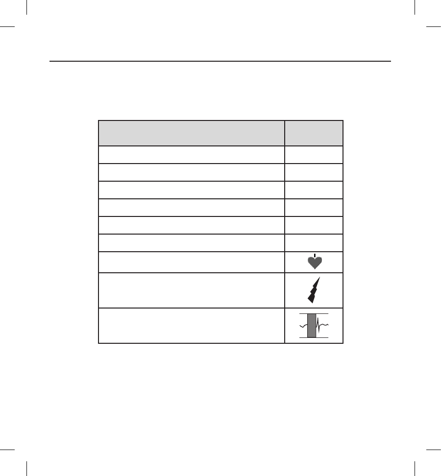
50
S-ECG Rhythm Strip Markers
The system provides S-ECG annotations (Table 13) to identify specic events during a recorded episode. Sample annotations
are shown for the programmer display (Figure 9) and the printed report (Figure 10).
Table 13: S-ECG Markers on Programmer Display Screens and Printed Reports
Description Marker
ChargingaC
Sensed Beat S
Noisy Beat N
Paced Beat P
Tachy Detection T
Discard Beat •
Return to NSRa
Shock
Episode data compressed or not available
a Marker present on printed report but not on programmer display screen.
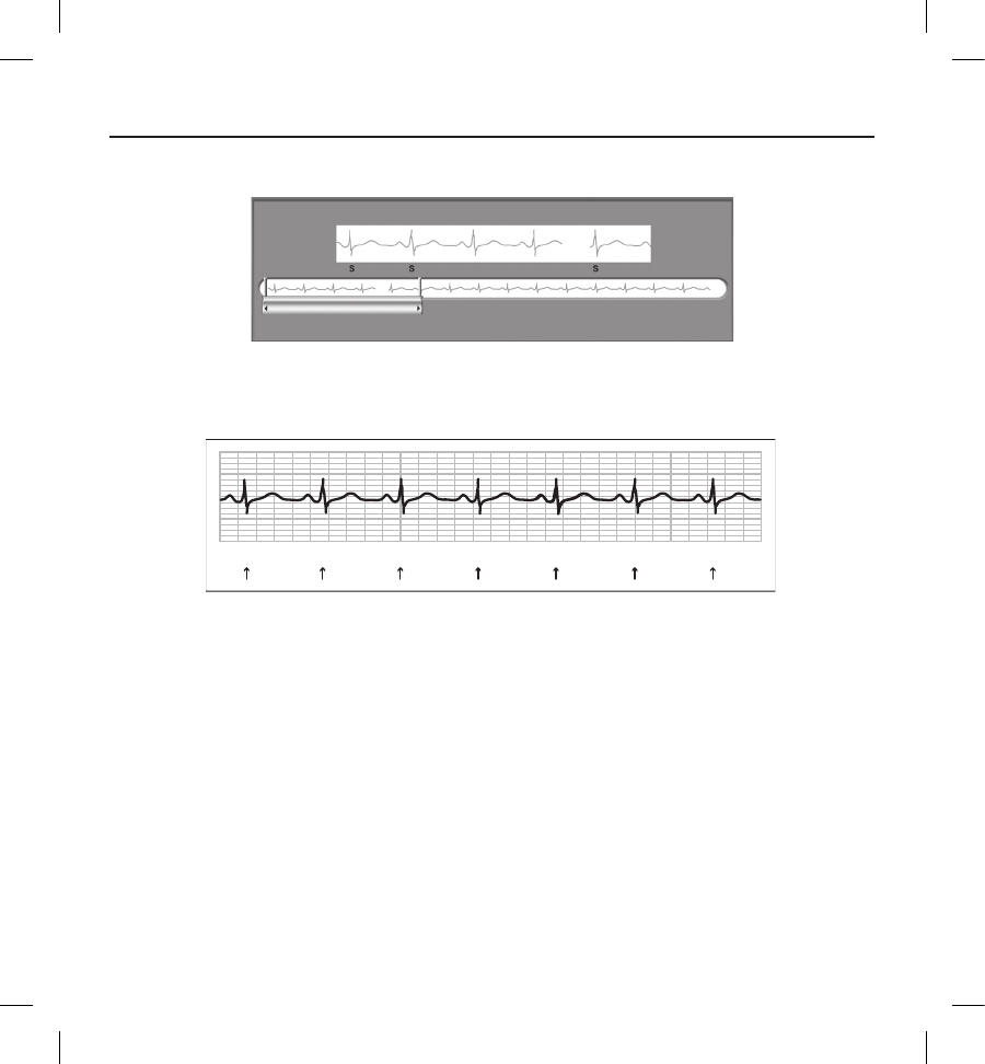
51
Figure 9: Programmer display markers
Patient Data
The device can store the following patient data, which can be retrieved and updated through the programmer:
• Patient’s name
• Physician’s name and contact information
• Device and subcutaneous electrode identication information (model and serial numbers) and implant
date
• Patient Notes (displayed upon connection to the device)
S S S SSSS
Figure 10: Printed Report Markers
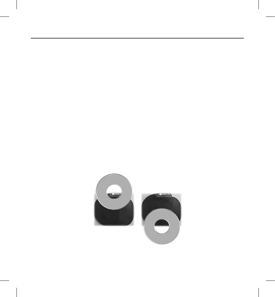
52
S-ICD System Magnet Use
The Boston Scientic magnet Model 6860 (the magnet) is a non-sterile accessory that may be used to temporarily inhibit the
delivery of therapy from the device if necessary. The Cameron Health magnet Model 4520 may be used interchangeably with
the Boston Scientic magnet for this purpose.
Note: When long duration therapy suspension is desired, it is recommended to modify pulse generator behavior
with the programmer rather than the magnet whenever possible.
To suspend therapy using a magnet:
1. APPLY the magnet over the device header or over the lower edge of the device as illustrated in Figure 11.
2. LISTEN for beeping tones (use a stethoscope if necessary). Therapy is not suspended until beeping tones are heard.
If no beeping is heard, try other positions within the target zones illustrated in Figure 12 until beeping tones are
heard. Maintain the magnet in each tested position for one second (it takes approximately one second for the pulse
generator to respond to the magnet).
3. HOLD the magnet in place to keep therapy suspended. Beeping will continue for 60 seconds while the magnet is held
in place. After 60 seconds, beeping stops, but therapy continues to be inhibited unless the magnet has been moved.
Note: If it is necessary to conrm therapy is still being inhibited after beeping has stopped, remove and
replace the magnet to reactivate the beeping tones. This step can be repeated as necessary.
4. REMOVE the magnet to resume normal pulse generator operation.
Figure 11: Starting position of the magnet for suspension of therapy
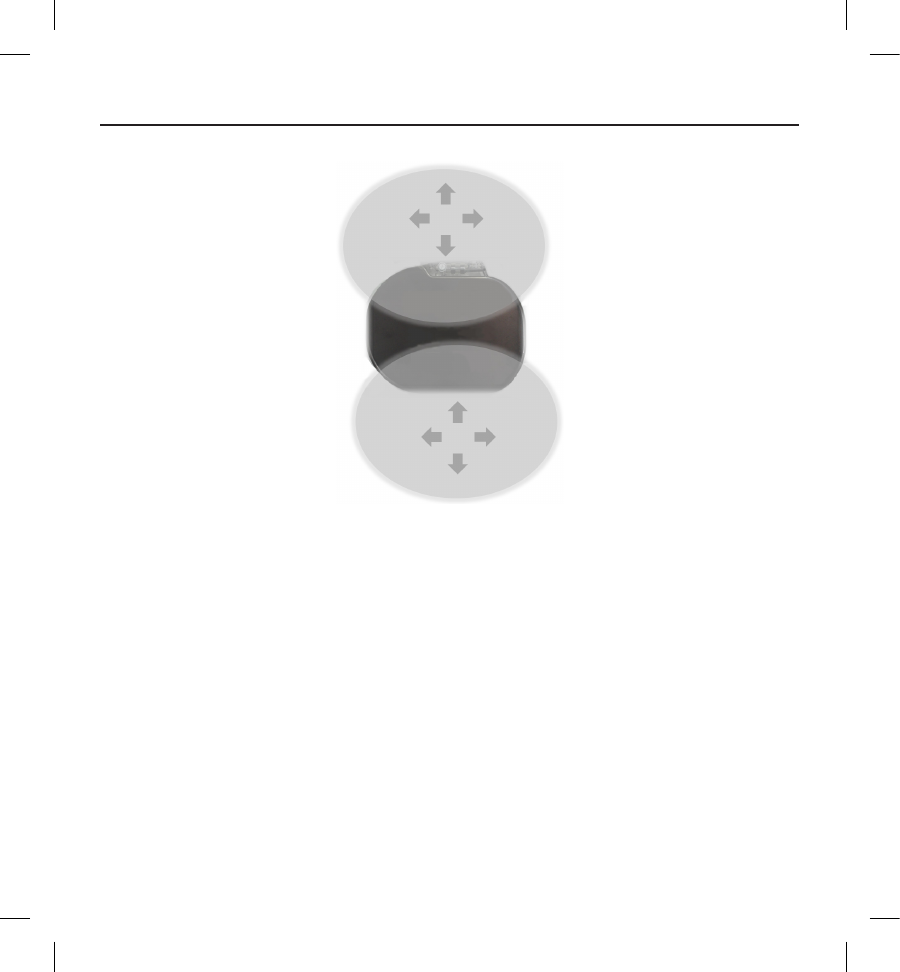
53
Figure 12: Grey shading indicates the zone within which magnet placement is most likely to suspend therapy, as signaled by
beeping tones. Sweep the magnet vertically and horizontally across the target zone as indicated by the arrows.
Magnet use for patients with deep implant placement
Consider the following when using the magnet on patients with deep implant placement:
• If the exact location of the pulse generator is not evident, the magnet may need to be tested across a
broader region of the body surrounding the anticipated pulse generator location. Unless beeping tones
are heard, therapy has not been suspended.
• Beeping from a device with a deep implant location may be dicult to hear. Use a stethoscope if
necessary. Correct magnet placement can only be conrmed by detection of the beeping tones.
• Multiple magnets may be used in a stacked conguration to increase the likelihood of eliciting the
beeping and associated inhibition of therapy.
• If beeping tones cannot be detected, it may be necessary to use the programmer to suspend therapy in
these patients.
54
Warning: In patients with a deep implant placement (greater distance between the magnet and the pulse
generator) magnet application may fail to elicit the magnet response. In this case the magnet cannot be used
to inhibit therapy.
Magnet Response and Pulse Generator Mode
The eect of the magnet on the pulse generator varies depending on the Mode the pulse generator is programmed to (Shelf,
Therapy On, or Therapy O) as shown in Table 14.
Table 14: Magnet Response
Pulse Generator Mode Magnet Response
Shelf Mode • A single beep sounds when the magnet is detected
Therapy On
• Arrhythmia detection and therapy response are suspended until
the magnet is removed
• The beeper sounds with each detected QRS complex for 60
seconds or until the magnet is removed, whichever occurs rst
• Programmer commanded rescue shocks and manual shocks are
aborted if the magnet is applied after the shock is commandeda
• Post-shock pacing is terminated
• Arrhythmia induction testing is prohibited
Therapy O
• The beeper sounds with each detected QRS complex for 60
seconds or until the magnet is removed, whichever occurs rst
• Programmer commanded rescue shocks and manual shocks are
aborted if the magnet is applied after the shock is commandeda
• Post-shock pacing is terminated
a Programmer commanded rescue shocks and manual shocks are delivered if they are commanded with the magnet already in
place
Note: If the magnet is applied during an episode, the episode will not be stored in the device memory.
Note: Magnet application does not aect wireless communication between the device and the programmer.

55
Bidirectional Torque Wrench
A torque wrench (model 6628) is included in the sterile tray with the pulse generator, and is designed for tightening and
loosening #2-56 setscrews, captured setscrews, and setscrews on this and other Boston Scientic pulse generators and lead
accessories that have setscrews that spin freely when fully retracted (these setscrews typically have white seal plugs).
This torque wrench is bidirectional, and is preset to apply adequate torque to the setscrew and will ratchet when the
setscrew is secure. The ratchet release mechanism prevents overtightening that could result in device damage. To facilitate
the loosening of tight extended setscrews, this wrench applies more torque in the counterclockwise direction than in the
clockwise direction.
Note: As an additional safeguard, the tip of the torque wrench is designed to break o if used to overtighten
beyond preset torque levels. If this occurs, the broken tip must be extracted from the setscrew using forceps.
This torque wrench may also be used for loosening setscrews on other Boston Scientic pulse generators and lead accessories
that have setscrews that tighten against a stop when fully retracted (these setscrews typically have clear seal plugs). However,
when retracting these setscrews, stop turning the torque wrench when the setscrew has come in contact with the stop. The
additional counterclockwise torque of this wrench may cause these setscrews to become stuck if tightened against the stop.
Using the EMBLEM S-ICD Pulse Generator
Items Included in Package
The device has been sterilized with ethylene oxide gas and is packaged in a sterile container that is suitable for use in the
operating eld. Store in a clean, dry area. Each package contains the following:
• One EMBLEM S-ICD pulse generator Model A209
• One bidirectional torque wrench
• One EMBLEM S-ICD pulse generator Model A209 user’s manual
Note: Accessories (e.g. wrenches) are intended for one-time use only. They should not be resterilized or reused.
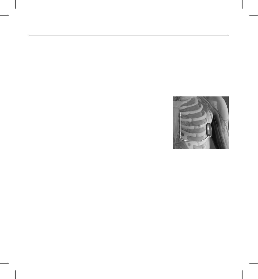
56
Implanting the S-ICD System
This section presents the information necessary for implanting and testing the S-ICD System, including:
• Implanting the EMBLEM S-ICD pulse generator (the “device”)
• Implanting the EMBLEM S-ICD subcutaneous electrode (the “electrode”) using the EMBLEM S-ICD
subcutaneous electrode insertion tool (the “EIT”)
• Setting up and testing the device using the EMBLEM S-ICD programmer (the “programmer”).
Warning: All Boston Scientic S-ICD implantable components are designed for use with the Boston Scientic or
Cameron Health S-ICD System only. Connection of any S-ICD System components to a non-
compatible component will result in failure to deliver life-saving debrillation therapy.
The S-ICD System is designed to be positioned using anatomical landmarks. However,
it is recommended to review a pre-implant chest x-ray in order to conrm that a
patient does not have notably atypical anatomy (e.g. dextrocardia). Additionally, it
is not recommended to deviate from the implant instructions to accommodate for
physical body size or habitus, unless a pre-implant chest x-ray has been reviewed.
The device and subcutaneous electrode are typically implanted subcutaneously in the
left thoracic region (Figure 13). The EIT is used to create the subcutaneous tunnels in
which the electrode is inserted.
Figure 13: Placement of the S-ICD System
Check Equipment
It is recommended that instrumentation for cardiac monitoring and debrillation be available during the implant procedure.
This includes the S-ICD System Programmer with its related accessories and the software application. Before beginning the
implantation procedure, become completely familiar with the operation of all the equipment and the information in the
respective user’s manuals. Verify the operational status of all equipment that may be used during the procedure. In case of
accidental damage or contamination, the following should be available:
• Sterile duplicates of all implantable items
• Wand in a sterile barrier
• Torque and non-torque wrenches
During the implantation procedure, always have a standard transthoracic debrillator with external pads or paddles available
for use during debrillation threshold testing.
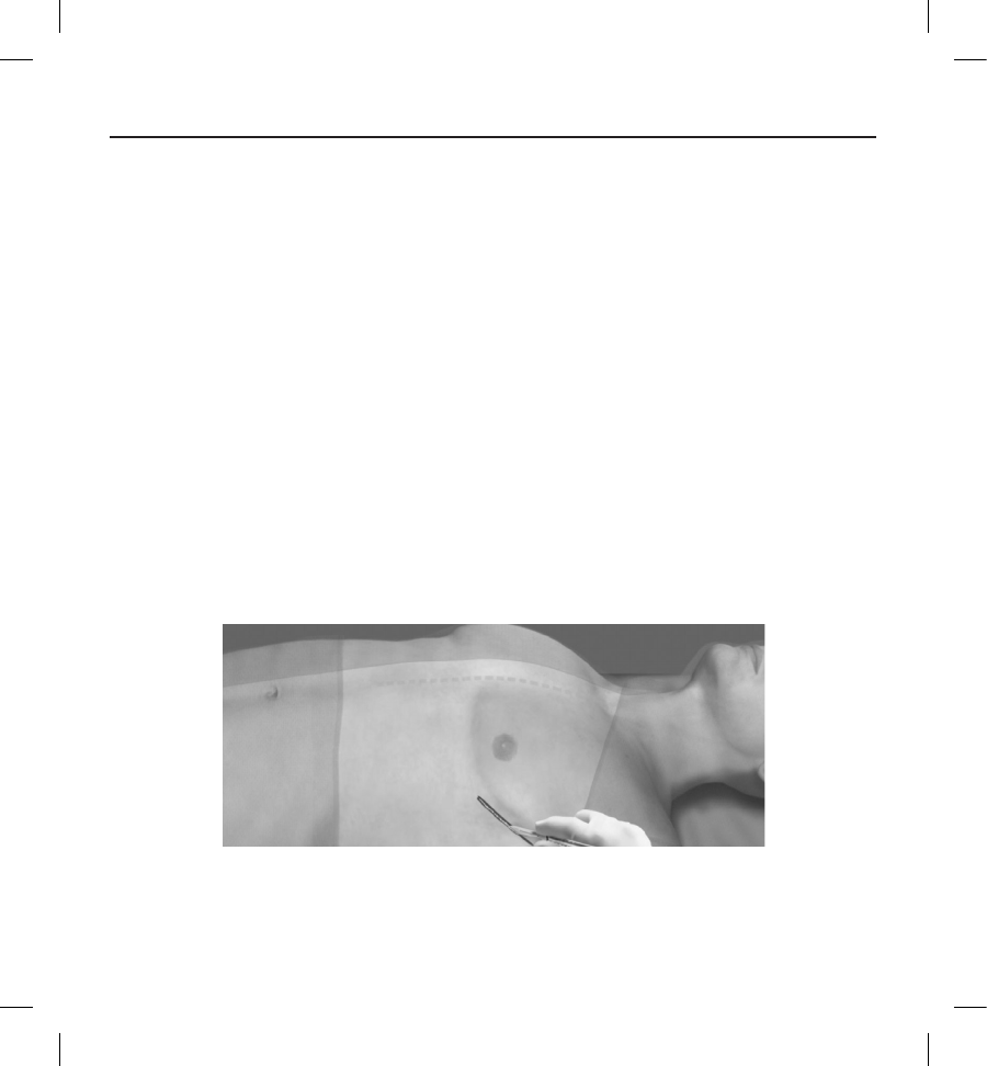
57
Interrogate and Check the Pulse Generator
To maintain sterility, test the pulse generator as described below before opening the sterile blister tray. The pulse generator
should be at room temperature to ensure accurately measured parameters.
1. Place the wand directly over the pulse generator.
2. From the programmer startup screen, select the Scan for Devices button.
3. Identify the pulse generator being implanted from the Device List screen and verify that the status of the pulse
generator is reported as 'Not Implanted'. This indicates the pulse generator is in Shelf Mode. If otherwise, contact
Boston Scientic using the information on the back cover.
4. From the Device List screen, select the pulse generator being implanted to initiate a communication session.
5. Upon connection with the pulse generator, the programmer will display an alert if the pulse generator battery status
is below the appropriate level for a device at implant. If a battery alert appears, contact Boston Scientic using the
information on the back cover.
Creating the Device Pocket
The device is implanted in the left lateral thoracic region. To create the device pocket, make an incision such that the device
can be placed in the vicinity of the left 5th and 6th intercostal spaces and near the mid-axillary line (Figure 14). This can be
accomplished by making an incision along the inframammary crease.
Figure 14: Creating the device pocket
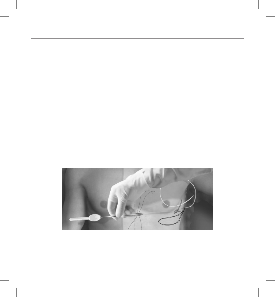
58
Implanting the EMBLEM S-ICD Subcutaneous Electrode
The procedure described below is one of several surgical approaches that can be used to appropriately implant and position
the electrode. Regardless of the surgical approach, the debrillation coil must be positioned parallel to the sternum, in close
proximity to, or in contact with the deep fascia, approximately 2 cm from the sternal midline (Figure 13). In addition, good
tissue contact with the electrode and pulse generator is important to optimize sensing and therapy delivery. Use standard
surgical techniques to obtain good tissue contact. For example, keep the tissue moist and ushed with sterile saline, express
any residual air out through the incisions prior to closing and, when closing the skin, take care not to introduce air into the
subcutaneous tissue.
1. Make a small, 2 cm horizontal incision at the xiphoid process (xiphoid incision).
Note: If desired, in order to facilitate attachment of the suture sleeve to the fascia following electrode
placement, two suture ties to the fascia can be made at the xiphoid incision prior to continuing.
2. Insert the distal tip of the EIT at the xiphoid incision and tunnel laterally until the distal tip emerges at the device
pocket.
Note: The EIT is malleable and can be curved to match the patient's anatomical prole.
Caution: Use only the electrode insertion tool to create the subcutaneous tunnel when implanting and
positioning the subcutaneous electrode.
Figure 15: Connecting the distal end of the subcutaneous electrode to the EIT
3. Using conventional suture material, tie the anchoring hole of the subcutaneous electrode to the EIT creating a long
15-16 cm loop (Figure 15).
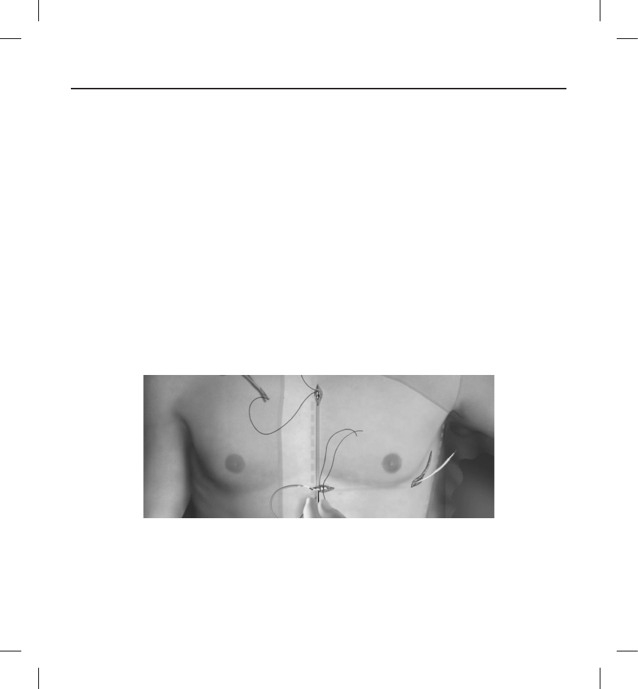
59
4. With the subcutaneous electrode attached, carefully pull the EIT back through the tunnel to the xiphoid incision until
the proximal sensing electrode emerges.
5. Place a suture sleeve over the subcutaneous electrode shaft 1 cm below the proximal sensing electrode. Using
the preformed grooves, bind the suture sleeve to the subcutaneous electrode shaft using 2-0 silk or similar
non-absorbable suture material, making sure not to cover the proximal sensing electrode. Check the suture sleeve
after anchoring to assure stability by grasping the suture sleeve with ngers and trying to move the subcutaneous
electrode in either direction.
Note: Do not secure the suture sleeve and subcutaneous electrode to the fascia until electrode placement is
complete
6. Make a second incision approximately 14 cm superior to the xiphoid incision (superior incision). If desired, place the
exposed subcutaneous electrode on the skin to make this measurement. The distance between the superior and
xiphoid incisions must accommodate the portion of the subcutaneous electrode from the distal sensing electrode to
the proximal sensing electrode. Pre-place one or two fascial sutures in superior incision. Use a non-absorbable suture
material of appropriate size for long term retention. Apply gentle traction to ensure adequate tissue xation. Retain
the needle on the suture for later use in passing through the electrode anchoring hole.
7. Insert the distal tip of the EIT into the xiphoid incision and tunnel subcutaneously towards the superior incision,
staying as close to the deep fascia as possible (Figure 16).
Figure 16: Tunneling to Superior Incision
8. Once the distal tip of the EIT emerges from the superior incision, disconnect and retain the suture loop from the distal
tip of the EIT. Secure the ends of the suture with a surgical clamp. Remove the EIT.
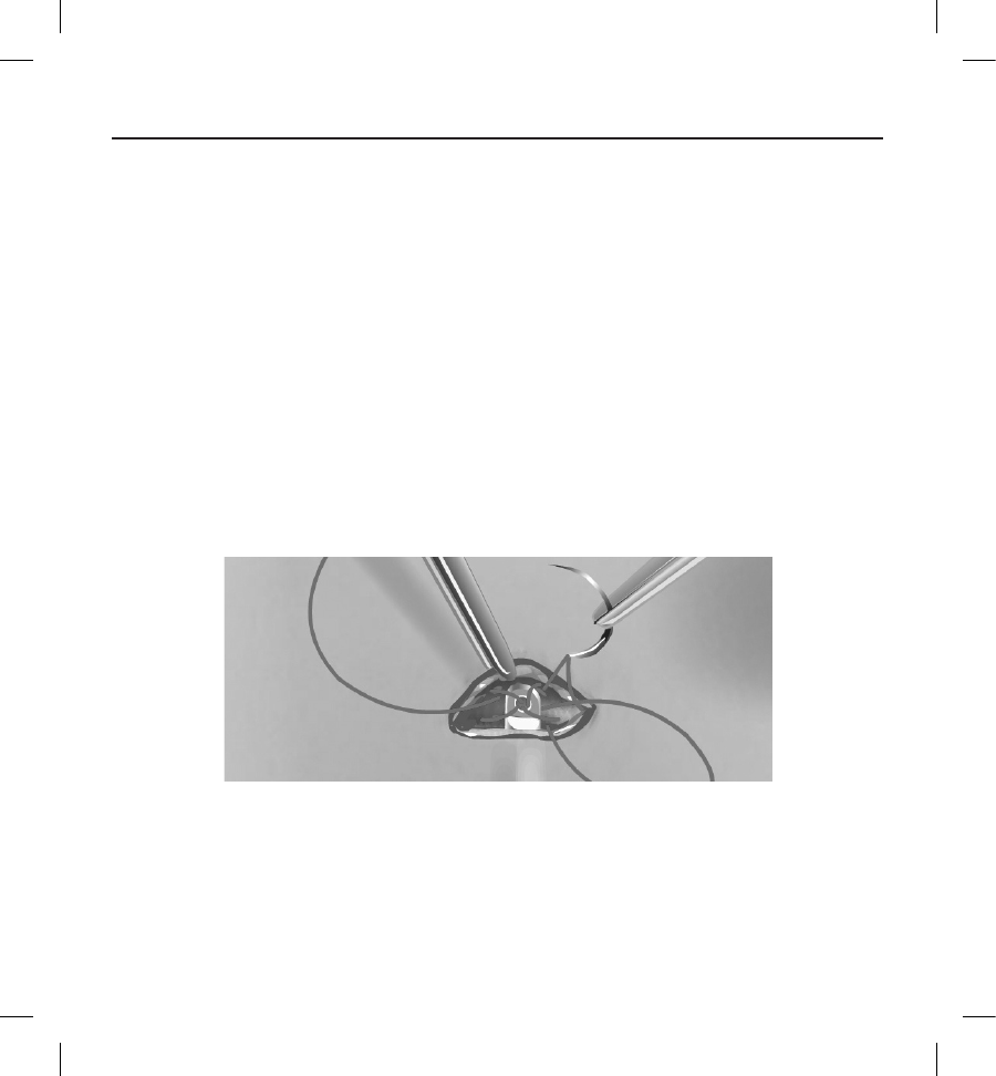
60
9. Using the secured suture at the superior incision, carefully pull the suture and subcutaneous electrode through the
tunnel until the anchoring hole emerges. The subcutaneous electrode should be parallel to the sternal midline with
the debrillation coil in close proximity to the deep fascia.
10. Cut and discard the suture material.
11. At the xiphoid incision, secure the suture sleeve with the subcutaneous electrode to the fascia using 2-0 silk or similar
non-absorbable suture material.
Warning: Use appropriate anchoring techniques as described in the implant procedure to prevent S-ICD
System dislodgement and/or migration. Dislodgement and/or migration of the S-ICD System may result in an
inappropriate shock or failure to deliver therapy to the patient.
Caution: Do not suture directly over the subcutaneous electrode body, as this may cause structural damage.
Use the suture sleeve to prevent subcutaneous electrode movement.
Caution: Suture only those areas indicated in the implant instructions.
Note: Ensure that the suture is securely fastened to fascia by gently tugging on the suture prior to tying to the
suture sleeve and subcutaneous electrode.
12. At the superior incision, secure the anchoring hole to the fascia using the pre-placed sutures from step 6 (Figure 17).
Figure 17: Anchoring the distal tip of the subcutaneous electrode
Note: Ensure that the suture is securely fastened to fascia by gently tugging on the suture prior to tying to the
subcutaneous electrode anchoring hole.
13. Gently tug the subcutaneous electrode at the superior incision to ensure the anchoring hole is secured to the fascia.
14. To dispose of the EIT, return the used product to the original package, then dispose in a biohazard container.

61
15. To ensure good tissue contact with the implanted subcutaneous electrode, ush the xiphoid and superior incisions
with sterile saline solution and apply rm pressure along the electrode to express any residual air out through the
incisions prior to closing.
Connecting the Subcutaneous Electrode to the Device
When connecting the subcutaneous electrode to the device, use only the tools provided in the device tray. Failure to use the
supplied tools may result in damage to the setscrew. Retain the tools until all testing procedures are complete and the device
is implanted.
Caution: Verify the device is in Shelf mode or Therapy O to prevent the delivery of unwanted shocks to the
patient or the person handling the device during the implant procedure.
Note: Avoid allowing blood or other body uids to enter the connector port in the device header. If blood or other
body uids inadvertently enter the connector port, ush with sterile water.
Note: Do not implant the device if the setscrew seal plug appears to be damaged.
1. If applicable, remove and discard the tip protection before using the torque wrench.
2. Gently insert the torque wrench blade into the setscrew by passing it through the preslit, center depression of the
seal plug at a 90° angle (Figure 18). This will open up the seal plug, relieving any potential pressure build-up from the
connector port by providing a pathway to release trapped uid or air.
Note: Failure to properly insert the torque wrench in the preslit depression of the seal plug may result in
damage to the plug and its sealing properties.
Caution: Do not insert the subcutaneous electrode into the pulse generator connector port without taking the
following precautions to ensure proper insertion:
• Insert the torque wrench into the preslit depression of the seal plug before inserting the subcutaneous
electrode connector into the port, to release any trapped uid or air.
• Visually verify that the setscrew is suciently retracted to allow insertion. Use the torque wrench to loosen
the setscrew if necessary.
• Fully insert the subcutaneous electrode connector into the port and then tighten the setscrew onto the
connector.
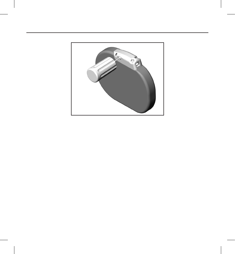
62
Figure 18: Inserting the torque wrench
3. With the torque wrench in place, fully insert the subcutaneous electrode terminal into the electrode port. Grip the
subcutaneous electrode close to the connector and insert it straight into the connector port. The electrode is fully
inserted when the tip of the connector is visible beyond the connector block when viewed from the top. Refer to
Figure 19 for illustrations of the header connector block with no electrode inserted (top panel) and with the electrode
fully inserted (bottom panel). Place pressure on the subcutaneous electrode to maintain its position and ensure that
it remains fully inserted in the connector port.
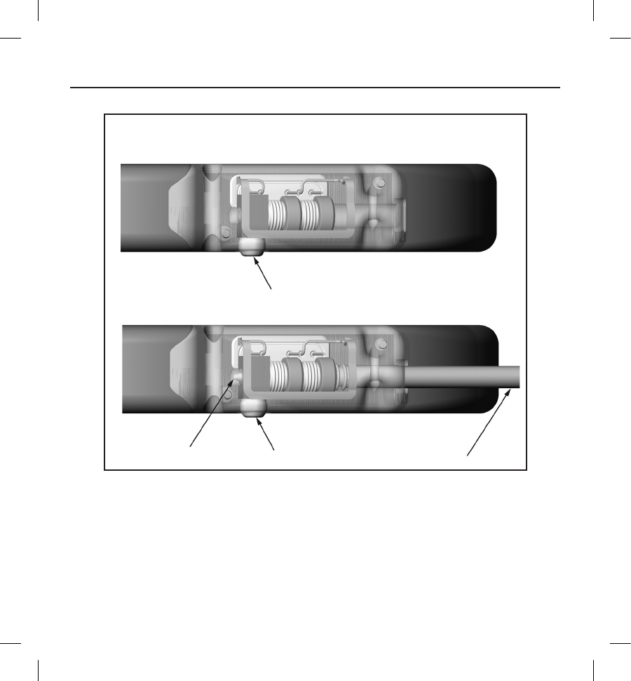
63
TOP VIEW
No electrode inserted
Electrode fully inserted
Figure 19: Position of the subcutaneous electrode connector
Warning: Use caution handling the subcutaneous electrode connector. Do not directly contact the connector
with any surgical instruments such as forceps, hemostats, or clamps. This could damage the connector. A
damaged connector may result in compromised sealing integrity, possibly leading to compromised sensing,
loss of therapy, or inappropriate therapy.
Caution: Do not bend the subcutaneous electrode near the subcutaneous electrode-header interface.
Improper insertion can cause insulation or connector damage.
Note: If necessary, lubricate the connector sparingly with sterile water to make insertion easier.
Setscrew
Setscrew
Tip of connector Electrode
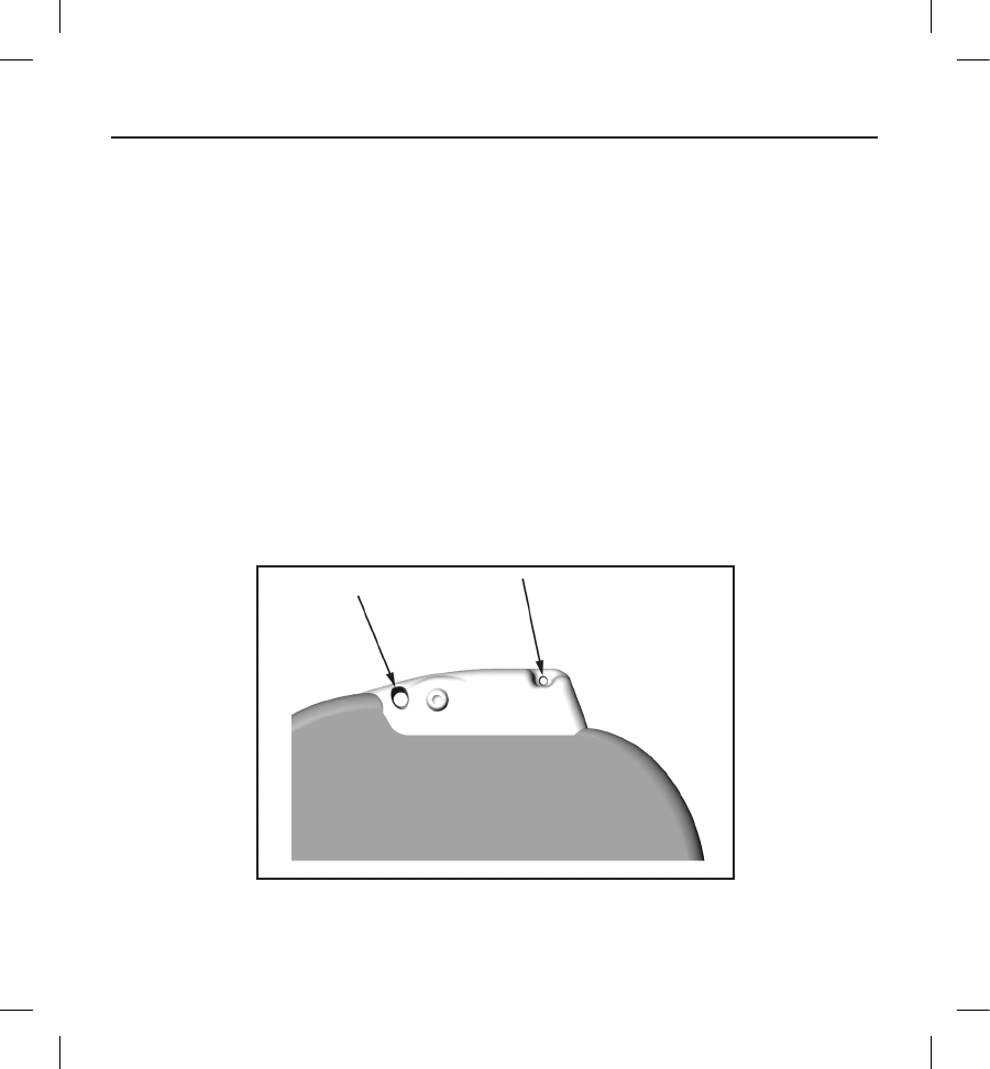
64
4. Apply gentle downward pressure on the torque wrench until the blade is fully engaged within the setscrew cavity,
taking care to avoid damage to the seal plug. Tighten the setscrew by slowly turning the torque wrench clockwise,
until it ratchets once. The torque wrench is preset to apply the proper amount of force to the captive setscrew;
additional rotation and force is unnecessary.
5. Remove the torque wrench.
6. Apply gentle traction to the subcutaneous electrode to ensure a secure connection.
7. If the subcutaneous electrode terminal is not secure, attempt to reseat the setscrew. Reinsert the torque wrench as
described above, and loosen the setscrew by slowly turning the wrench counterclockwise, until the subcutaneous
electrode is loose. Then repeat the sequence above.
8. Insert the device into the subcutaneous pocket, with any excess subcutaneous electrode placed underneath the
device.
9. Anchor the device to the fascia to prevent possible migration using conventional 0- silk or similar non-absorbable
suture material. Two suture holes are provided in the header for this purpose (Figure 20).
10. Flush the pulse generator pocket with sterile saline solution and ensure there is good contact between the pulse
generator and the surrounding tissue of the pocket prior to closing the rst layer of tissue and prior to performing
Automatic Setup of the device.
Figure 20: Header suture holes for anchoring the device
11. Perform Automatic Setup as described on page 65 of this manual.
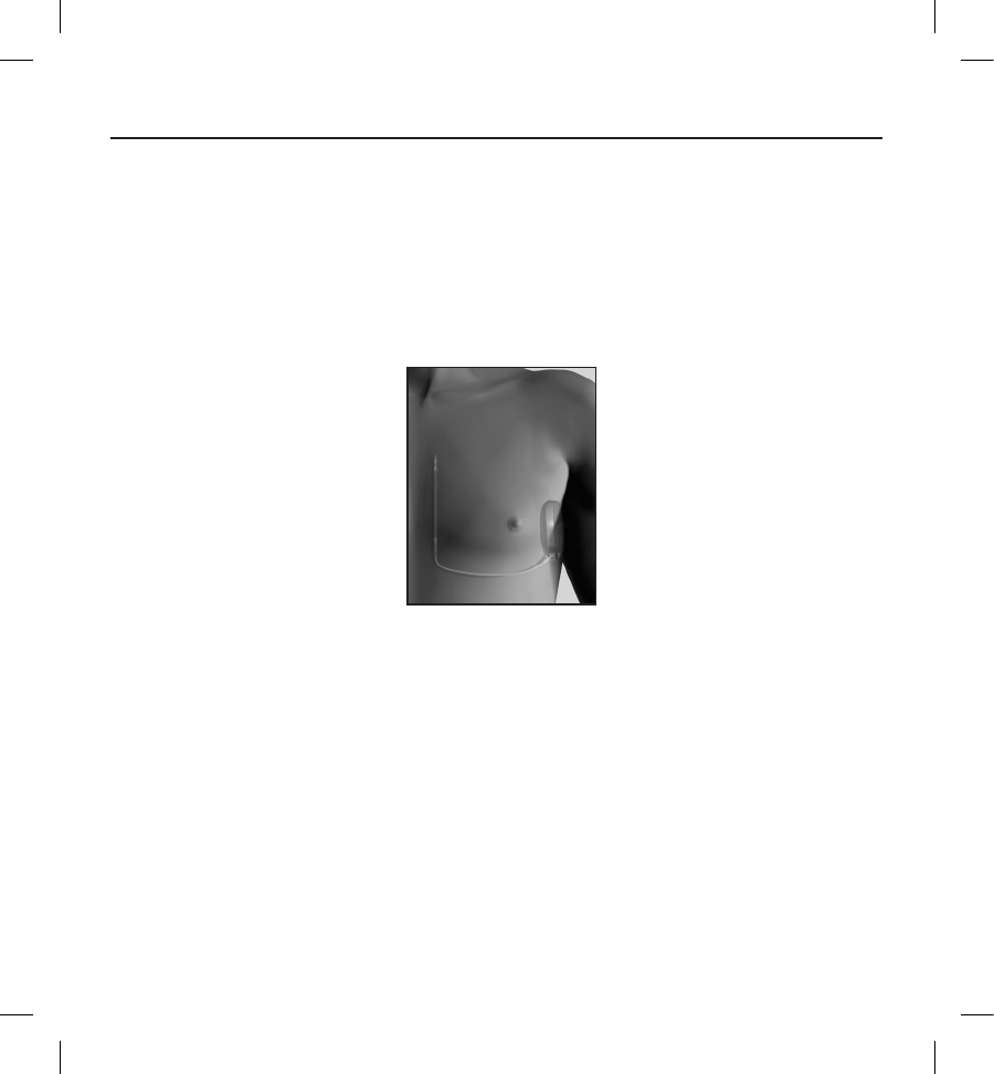
65
12. After performing Automatic Setup, and with the device mode still set to Therapy O, palpate the subcutaneous
electrode while monitoring the real-time S-ECG on the programmer screen for evidence of inappropriate sensing.
If inappropriate sensing is observed, do not proceed until it is resolved. Contact Boston Scientic for assistance if
necessary. Once the baseline is stable and appropriate sensing is observed, set the device mode to Therapy On and
conduct debrillation testing if desired. (See page 66 of this manual for Debrillation testing instructions.)
13. After device setup and debrillation testing, close all incisions. Use standard surgical techniques to achieve good
tissue contact with both the subcutaneous electrode and pulse generator, for example avoiding any air entrapment in
the subcutaneous tissue.
Figure 21: System placement after closure of all incisions
Setting up the EMBLEM S-ICD Pulse Generator using the Model 3200 S-ICD Programmer
A brief setup process must be completed before the device can deliver manual or automatic therapy. Additional details can be
found in the EMBLEM S-ICD Model 3200 Programmer User's Manual. This process can be performed automatically or manually
during the implant procedure, although Automatic Setup is recommended. During setup, the system automatically:
• Conrms entry of the subcutaneous electrode model and serial numbers.
• Measures the shock electrode impedance.
• Optimizes the sense electrode conguration.
• Optimizes the gain selection.
• Acquires a reference NSR template.

66
To initiate the Automatic Setup process:
1. After using the programmer to scan for devices, choose the device being implanted from the Device List screen.
2. The programmer will connect to the chosen pulse generator and the Device Identication screen will appear.
Choosing the Continue button from this screen removes the pulse generator from Shelf Mode and causes the
Automatic Setup screen to appear.
3. Select the Automatic Setup button to initiate Automatic Setup.
4. Follow the on-screen instructions to complete the Automatic Setup sequence.
If the patient’s heart rate is greater than 130 bpm, you will be instructed to complete the Manual Setup process instead. To
initiate the Manual Setup process:
1. From the Main Menu screen, select the Utilities button.
2. From the Utilities screen, select the Manual Setup button.
You will be guided through a manual impedance test, selection of sensing vector, selection of gain setting, and acquisition of
a reference S-ECG.
Debrillation Testing
Once the device is implanted and programmed to Therapy On, debrillation testing may be conducted. A 15J safety margin is
recommended for debrillation testing.
Note: Debrillation testing is recommended at implant to conrm the ability of the S-ICD System to sense and
convert VF.
Warning: Always have external debrillation equipment and medical personnel skilled in CPR available during
implant and follow-up testing. If not terminated in a timely fashion, an induced ventricular tachyarrhythmia can
result in the patient’s death.
To induce VF and test the S-ICD System using the Model 3200 S-ICD programmer:
1. Select the Main Menu icon (arrow within a circle) in the Navigation bar, in the top right corner of the screen.
2. From the Main Menu screen, select the Patient Test button to setup the induction test.
3. Follow the on-screen instructions to set shock energy and polarity and to induce an arrhythmia.
Note: Ensure that noise markers (“N”) are not present on the S-ECG prior to induction. The presence of noise
markers may delay detection and therapy delivery.
4. At any time prior to therapy delivery, the programmed energy may be aborted by selecting the red Abort button.

67
5. Select the Exit button to exit the induction process and return to the Main Menu screen.
The following functions occur during the test:
• The S-ICD System induces ventricular brillation using 200 mA alternating current (AC) at 50 Hz.
Induction continues until the Hold To Induce button is released (up to a maximum of 10 seconds per
attempt).
Note: If necessary, the induction can be terminated by disconnecting the wand from the
programmer.
• Arrhythmia detection and the Live S-ECG are suspended during AC induction. Once the Hold to Induce
button is released, the programmer displays the patient’s rhythm.
• Upon detection and conrmation of an induced arrhythmia, the S-ICD System automatically delivers a
shock at the programmed energy output and polarity.
Note: Whenever the programmer is in active communication with an S-ICD pulse generator,
charging of the pulse generator in preparation for delivering a shock (whether commanded or in
response to a detected arrhythmia) is indicated by an audible notication. The notication continues
until the shock is delivered or aborted.
• If the shock fails to convert the arrhythmia, re-detection occurs and subsequent shocks are delivered at
the pulse generator’s maximum energy output (80 J).
Note: The EMBLEM S-ICD pulse generator can deliver a maximum of ve shocks per episode. At any
time, an 80 J rescue shock can be delivered by pressing the Rescue Shock button.
Note: Following the release of the Hold To Induce button, evaluate the sensing markers during the
induced rhythm. The S-ICD System uses a lengthened rhythm detection period. Consistent tachy
“T” markers indicate that tachyarrhythmia detection is occurring, and that capacitor charging is
imminent. If a high degree of amplitude variation is noted during the arrhythmia, a slight delay may
be expected prior to capacitor charging or shock delivery.
If appropriate sensing or VF conversion cannot be demonstrated, consider changing the selected sense conguration or
relocating the subcutaneous electrode or device and then retest. VF conversion testing can be conducted in either polarity.
Complete and Return the Implantation Form
Within ten days of implantation, complete the Warranty Validation and Lead Registration form and return the original to
Boston Scientic along with copies of the Summary Report, Captured S-ECG Report, and Episode Report(s) printed from
the programmer. This information enables Boston Scientic to register each implanted pulse generator and subcutaneous
electrode, and provide clinical data on the performance of the implanted system. Keep a copy of the Warranty Validation and
Lead Registration form and programmer printouts for the patient’s le.

68
Patient Counseling Information
The following topics should be discussed with the patient prior to discharge.
• External debrillation—the patient should contact their physician to have their pulse generator system
evaluated if they receive external debrillation
• Beeping tones—the patient should contact their physician immediately if they hear tones coming from
their pulse generator
• Signs and symptoms of infection
• Symptoms that should be reported (e.g., lightheadedness, palpitations, unexpected shocks)
• Protected environments—the patient should seek medical guidance before entering areas protected by
a warning notice that prevents entry by patients who have a pulse generator
• Avoiding potential sources of EMI in home, work, and medical environments
• Persons administering CPR—the presence of voltage (tingling) on the patient’s body surface may be
experienced when the pulse generator delivers a shock
• Reliability of their pulse generator ("Product Reliability" on page 72)
• Activity restrictions (if applicable)
• Frequency of follow-up
• Travel or relocation—Follow-up arrangements should be made in advance if the patient is leaving the
country of implant
• Patient ID card—the patient should be advised to carry their patient ID card at all times (a temporary
patient ID card is provided with the device, and a permanent ID card will be sent to the patient 4 to 6
weeks after the implant form is received by Boston Scientic)
Patient Guide
A copy of the Patient Guide is available for the patient, patient’s relatives, and other interested people.
It is recommended that you discuss the information in the Patient Guide with concerned individuals both before and after
implantation so they are fully familiar with pulse generator operation.
For additional copies, contact Boston Scientic using the information on the back cover.

69
Post Implant Follow-Up Procedures
It is recommended that device functions be evaluated with periodic follow-up testing by trained personnel to enable review of
device performance and associated patient health status throughout the life of the device.
Warning: Always have external debrillation equipment and medical personnel skilled in CPR available during
implant and follow-up testing. If not terminated in a timely fashion, an induced ventricular tachyarrhythmia can
result in the patient’s death.
Immediately following the implant procedure, it is recommended that the following procedures be performed:
1. Interrogate the pulse generator and review the Device Status screen (refer to the EMBLEM S-ICD Programmer User's
Manual for additional information).
2. Perform sensing optimization (refer to Setting up the EMBLEM S-ICD Pulse Generator, page 65, for instructions on
performing Automatic Setup including sensing optimization)
3. Follow the on-screen instructions to capture a reference S-ECG
4. Print the Summary Report, Captured S-ECG Report, and Episode Report(s) to retain in the patient’s les for future
reference.
5. End session
During a follow-up procedure, it is recommended that the location of the subcutaneous electrode be periodically veried by
palpation and/or X-ray. When device communication with the programmer is established, the programmer automatically
noties the physician of any unusual conditions. Refer to the EMBLEM S-ICD Programmer User's Manual for more information.
Patient management and follow-up are at the discretion of the patient's physician, but are recommended one month after
implant and at least every 3 months to monitor the condition of the patient and evaluate device function. Oce visits may be
supplemented by remote monitoring where available.
Note: Because the duration of the device replacement timer is three months (starting when ERI is reached), three
month follow-up frequency is particularly important to ensure timely replacement of the device if necessary.
Caution: Successful VF or VT conversion during arrhythmia conversion testing is no assurance that conversion
will occur post-operatively. Be aware that changes in the patient’s condition, drug regimen, and other factors may
change the DFT, which may result in nonconversion of the arrhythmia post-operatively. Verify with a conversion
test that the patient’s tachyarrhythmias can be detected and terminated by the pulse generator system if the
patient’s status has changed or parameters have been reprogrammed.

70
Explantation
Note: Return all explanted pulse generators and subcutaneous electrodes to Boston Scientic. Examination of
explanted pulse generators and subcutaneous electrodes can provide information for continued improvement in
system reliability and warranty considerations.
Warning: Do not reuse, reprocess, or resterilize. Reuse, reprocessing, or resterilization may compromise the
structural integrity of the device and/or lead to device failure which, in turn, may result in patient injury, illness,
or death. Reuse, reprocessing, or resterilization may also create a risk of contamination of the device and/or cause
patient infection or cross-infection, including, but not limited to, the transmission of infectious disease(s) from
one patient to another. Contamination of the device may lead to injury, illness, or death of the patient.
Contact Boston Scientic:
• When a product is removed from service.
• In the event of patient death (regardless of cause), along with an autopsy report, if performed.
• Due to other observations or complications.
Note: Disposal of explanted pulse generators and/or subcutaneous electrodes is subject to applicable laws and
regulations. For a Returned Product Kit, contact Boston Scientic using the information on the back cover.
Caution: Be sure that the pulse generator is removed before cremation. Cremation and incineration temperatures
might cause the pulse generator to explode.
Caution: Before explanting, cleaning, or shipping the device, complete the following actions to prevent unwanted
shocks, overwriting of important therapy history data, and audible tones:
• Program the pulse generator to Therapy O mode
• If ERI or EOL has been reached, disable the beeper.
Clean and disinfect the device using standard biohazard handling techniques.
Consider the following items when explanting and returning the pulse generator and/or subcutaneous electrode:
• Interrogate the pulse generator and print all reports.
• Deactivate the pulse generator before explantation.
• Disconnect the subcutaneous electrode from the pulse generator.
• If subcutaneous electrode is explanted, attempt to remove it intact, and return it regardless of condition.
Do not remove the subcutaneous electrode with hemostats or any other clamping tool that may
damage it. Resort to tools only if manual manipulation cannot free the subcutaneous electrode.
• Wash, but do not submerge, the pulse generator and subcutaneous electrode to remove body uids and
debris using a disinfectant solution. Do not allow uids to enter the pulse generator’s connector port.
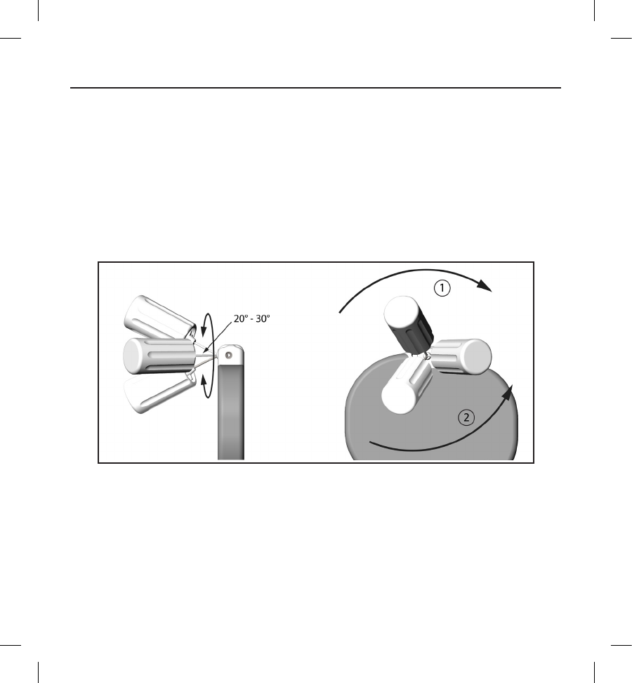
71
• Use a Boston Scientic Returned Product Kit to properly package the pulse generator and/or
subcutaneous electrode, and send it to Boston Scientic.
Loosening Stuck Setscrews
Follow these steps to loosen stuck setscrews:
1. From a perpendicular position, tilt the torque wrench to the side 20º to 30º from the vertical center axis of the
setscrew (Figure 22).
2. Rotate the wrench clockwise (for retracted setscrew) or counterclockwise (for extended setscrew) around the axis
three times, such that the handle of the wrench orbits the centerline of the screw (Figure 20). The torque wrench
handle should not turn or twist during this rotation.
[1] Clockwise rotation to free setscrews stuck in the retracted position [2] Counterclockwise rotation to free setscrews
stuck in the extended position
Figure 22: Rotating the torque wrench to loosen a stuck setscrew
3. As needed, you may attempt this up to four times with slightly more angle each time. If you cannot fully loosen the
setscrew, use the #2 torque wrench from Wrench Kit Model 6501.
4. Once the setscrew has been freed, it may be extended or retracted as appropriate.
5. Discard the torque wrench upon completion of this procedure.

72
Communication Compliance
Federal Communications Commission (FCC) Compliance
This transmitter is authorized by rule under the Medical Device Radiocommunication Service (in part 95 of the FCC Rules) and
must not cause harmful interference to stations operating in the 400.150 – 406.000 MHz band in the Meteorological Aids
(i.e., transmitters and receivers used to communicate weather data), the Meteorological Satellite, or the Earth Exploration
Satellite Services and must accept interference that may be caused by such stations, including interference that may cause
undesired operation. This transmitter shall be used only in accordance with the FCC Rules governing the Medical Device
Radiocommunication Service. Analog and digital voice communications are prohibited. Although this transmitter has been
approved by the Federal Communications Commission, there is no guarantee that it will not receive interference or that any
particular transmission from this transmitter will be free from interference.
This transmitter operates in the 402–405 MHz band using FSK modulation with radiated power conforming to the applicable
25 μW limit. The purpose of the transmitter is to communicate with the S-ICD System programmer to transfer data and to
receive and respond to programming commands.
Caution:Changes or modications not expressly approved by Boston Scientic could void the user’s authority to
operate the equipment.
FCC ID ESCCRMA20914
Additional Information
Product Reliability
It is Boston Scientic’s intent to provide implantable devices of high quality and reliability. However, these devices may exhibit
malfunctions that may result in lost or compromised ability to deliver therapy. These malfunctions may include the following:
• Premature battery depletion
• Sensing or pacing issues
• Inability to shock
• Error codes
• Loss of telemetry
Refer to Boston Scientic’s CRM Product Performance Report on www.bostonscientic.com for more information about device
performance, including the types and rates of malfunctions that these devices have experienced historically. While historical
data may not be predictive of future device performance, such data can provide important context for understanding the
overall reliability of these types of products.
73
Sometimes device malfunctions result in the issuance of product advisories. Boston Scientic determines the need to issue
product advisories based on the estimated malfunction rate and the clinical implication of the malfunction. When Boston
Scientic communicates product advisory information, the decision whether to replace a device should take into account the
risks of the malfunction, the risks of the replacement procedure, and the performance to date of the replacement device.
Pulse Generator Longevity
Based on simulated studies, it is anticipated that these pulse generators have average longevity to EOL as shown below. At
the time of manufacture, the device has the capacity for over 100 full energy shocks. The average projected longevity, which
accounts for the energy used during manufacture and storage, assumes the following conditions:
• 2 maximum energy charges at implant and 6 maximum energy shocks in the nal 3-month period
between ERI and EOL
• The pulse generator spends 6 months in Shelf mode during shipping and storage
• Telemetry use for 1 hour at implant and 30 minutes annually for in-clinic follow-up checks
• Standard use of the LATITUDE Communicator as follows: Weekly Device Check, monthly Full
Interrogations (scheduled remote follow-ups, and quarterly patient-initiated interrogations)
• With stored Episode Report Onset EGM
Table 15: Device longevity
Annual Full Energy Charges Average Projected Longevity (years)
3 (Normal Usea)7.3
46.7
56.3
a The median number of annual full energy charges seen in clinical testing of the rst generation S-ICD system was 3.3.
Note: The energy consumption in the longevity table is based upon theoretical electrical principles and veried
via bench testing only.
Full energy charges result from capacitor reformations, non-sustained episodes and delivered shocks.
Caution: Battery depletion will eventually cause the S-ICD Pulse Generator to stop functioning. Debrillation and
excessive numbers of charging cycles shorten the battery longevity.
Longevity is also aected in the following circumstances:
• A decrease in charging frequency may increase longevity
• An additional maximum energy shock reduces longevity by approximately 29 days
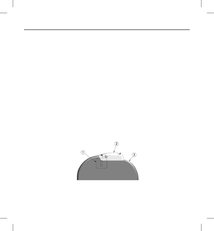
74
• One hour of additional telemetry reduces longevity by approximately 14 days
• Five patient-initiated LATITUDE Communicator interrogations per week for a year reduces longevity by
approximately 11 days
• An additional 6 months in Shelf mode prior to implant will reduce longevity by 103 days
Device longevity may also be aected by tolerances of electronic components, variations in programmed parameters, and
variations in usage as a result of patient condition.
Refer to the Device Status screen on the programmer and printed reports for an estimate of remaining battery capacity specic
to the implanted device.
Specications
Specications provided at 37° C ± 3° C, and assume a 75 Ohm (± 1%) load unless noted otherwise.
X-ray Identier
The pulse generator has an identier that is visible on x-ray lm or under uoroscopy. This identier provides noninvasive
conrmation of the manufacturer and consists of the following:
• The letters, BSC, to identify Boston Scientic as the manufacturer
• The number, 507, to identify the Model 2877 S-ICD programmer software application needed to
communicate with the pulse generator.
The x-ray identier is located in the pulse generator case, just below the header (Figure 23), and is read vertically.
Figure 23: Location of the x-ray ID; 1: x-ray identier location, 2: header, 3: pulse generator case
75
Table 16: Mechanical Specications
Model
Dimensions
W x H x D
(mm)
Mass (g) Volume (cm3)Connector
Typea
A209 83.1 x 69.1 x 12.7 130 59.5
SQ-1 S-ICD
connector (non-
standard)
a The EMBLEM S-ICD pulse generator is compatible with both the Cameron Health Model 3010 subcutaneous electrode and the
EMBLEM S-ICD subcutaneous electrode.
The pulse generator has a case electrode surface area of 111.0 cm2.
Material Speccations
• Case: hermetically sealed titanium, coated with titanium nitride
• Header: implantation-grade polymer
• Power Supply: lithium-manganese dioxide cell; Boston Scientic; 400530
76
Table 17: Programmable Parameters
Parameter Programmable Values Nominal
(as shipped)
Shock Zone 170 bpm – 250 bpm (steps of 10 bpm) 220 bpm
Conditional Shock
Zone
O, 170 bpm – 240 bpm
(If On, at least 10 bpm less than Shock Zone) 200 bpm
S-ICD Pulse
Generator Mode Shelf, Therapy On, Therapy O Shelf
Post-shock Pacing On, O O
Sensing
Conguration
Primary: Proximal electrode ring to device
Secondary: Distal electrode ring to device
Alternate: Distal electrode ring to proximal
electrode ring
Primary
Max Sensing Range x1 (± 4 mV)
x2 (± 2 mV) x1
Manual Shock 10 – 80 J (in steps of 5 J) 80 J
Smart Charge Resets to nominal 0 extensions
Polarity Standard: Phase 1 Coil (+)
Reverse: Phase 1 Coil (-) Standard
77
Table 18: Non-Programmable Parameters (Shock Therapy)
Parameter Value
SHOCK THERAPY
Delivered Energy 80 J
Peak Shock Voltage (80 J) 1328 V
Shock Tilt (%) 50%
Waveform Type Biphasic
Maximum Number of Shocks per
episode 5 shocks
Charge Time to 80 J (BOL/ERI)a≤10 sec / ≤15 secb
Sync Time Out 1 sec
Shock Sync Delay 100 ms
Post-Shock Blanking Period 1600 ms
a Charge time is one portion of the overall time-to-therapy. BOL refers to beginning of life.
b Under typical conditions.
78
Table 19: Non-Programmable Parameters (Post-Shock Pacing)
Parameter Value
POSTSHOCK PACING
Rate 50 ppm
Pacing Output 200 mA
Pulse Width (each phase) 7.6 ms
Waveform Biphasic
Polarity (rst phase) Standard: Phase 1 Coil (+)
Mode Inhibited Pacing
Duration 30 sec
Post-Pace Blanking Period/
Refractory Period
750 ms (rst pace pulse)
550 ms (subsequent pace pulses)
Runaway Protection 120 ppm
79
Table 20: Non-Programmable Parameters (Detection/Rhythm Discrimination, Fibrillation Induction, Sensing, Capacitor Reform
Schedule, Internal Warning System)
Parameter Value
DETECTION/RHYTHM DISCRIMINATION
X/Y for Initial Detection 18/24 intervals
X/Y for Redetection 14/24 intervals
Conrmation Before Shock 3 – 24 consecutive tachy intervals
Refractory Period Fast 160 ms, Slow 200 ms
FIBRILLATION INDUCTION
Frequency 50 Hz
Output 200 mA
Time out After Activation 10 sec
SENSING
Minimum Sensing Thresholda.08 mV
CAPACITOR REFORM SCHEDULE
Automatic Capacitor Reformation
Interval Approximately 4 monthsb
INTERNAL WARNING SYSTEM
High Impedance (sub-threshold) > 400 Ohms
High Impedance (delivered shock) > 200 Ohms
Maximum Charge Time out 44 sec
a With 10 Hz sine wave
b Reform can be delayed if capacitor was charged due to sustained/non-sustained arrhythmia in past 4 months
80
Table 21: Episode Data Parameters
Parameter Value
Treated Episodes 25 stored
Untreated Episodes 20 stored
Maximum Length per S-ECG Episode 128 sec
Captured S-ECG Report Up to 15 (12 sec each)
Table 22: Stored Patient Information
Patient Information (Stored Data)
Patient Name
Physician Name
Physician Contact Information
Device Model Number
Device Serial Number
Electrode Model Number
Electrode Serial Number
Patient Notes
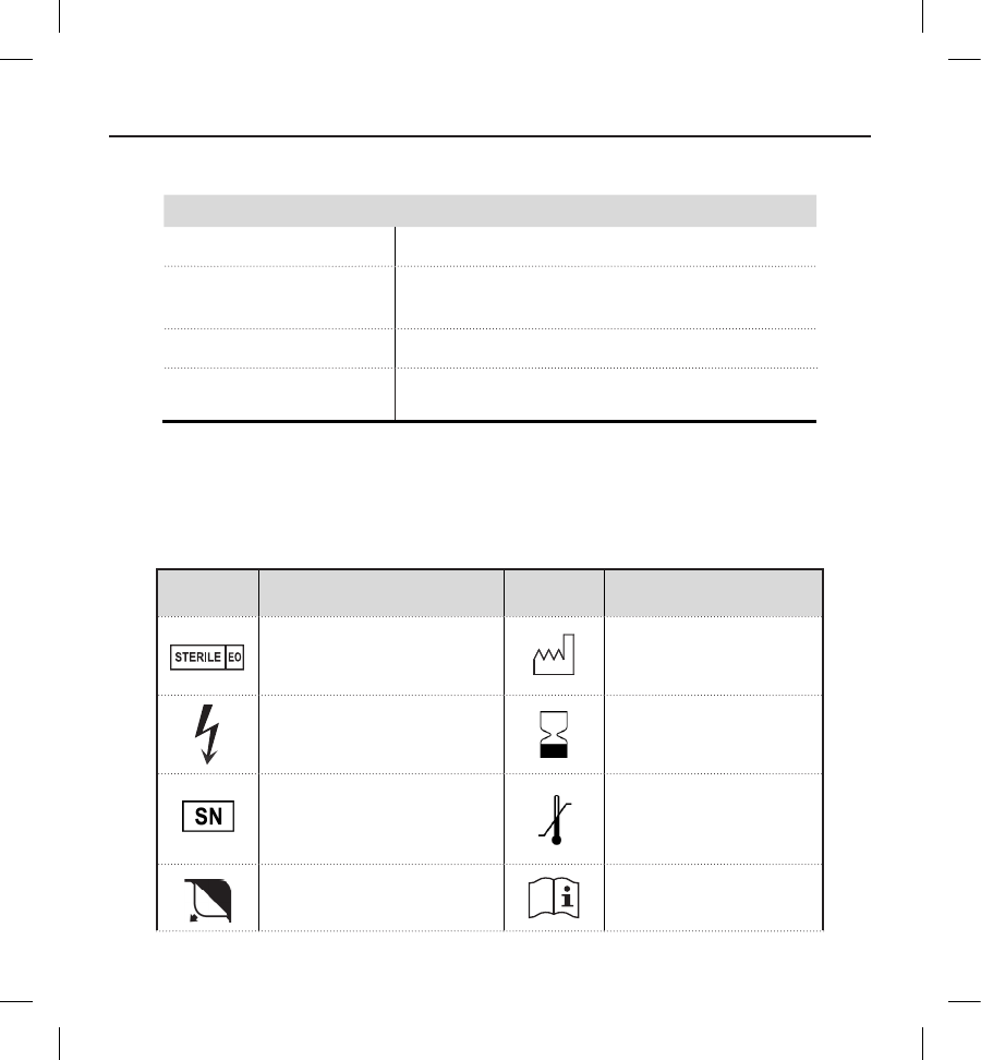
81
Table 23: Magnet Specications (Model 6860)
Component Specication
Shape Circular
Size Approximate Diameter: 2.8 in (7.2 cm)
Thickness: 0.5 in (1.3 cm)
Content Ferrous alloys coated with epoxy
Field Strength 90 gauss minimum when measured at a distance of 1.5 in (3.8 cm)
from magnet surface
Note: Specications are also applicable to the Cameron Health magnet Model 4520.
Denitions of Package Label Symbols
Table 24: Packaging Symbols: EMBLEM S-ICD Pulse Generator
Symbol Description Symbol Description
Sterilized using ethylene
oxide Date of manufacture
Dangerous voltage Use by
Serial number Temperature limitation
Open here Consult instructions for
use
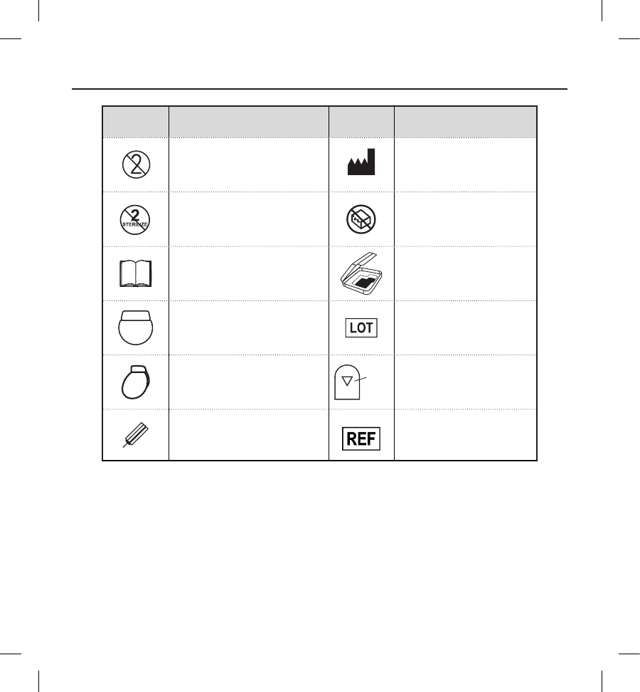
82
Symbol Description Symbol Description
Do not reuse Manufacturer
Do not resterilize Do not use if package is
damaged
Literature enclosed Package contents
Uncoated device Lot number
Pulse generator
SQ-1
SQ-1 S-ICD connector
(non-standard)
Torque wrench Reference number

83
S-ICD System and Pacemaker Interaction
Warning: Using multiple pulse generators could cause pulse generator interaction, resulting in patient injury or a
lack of therapy delivery. Test each system individually and in combination to help prevent undesirable interactions.
Interaction between the S-ICD System and a temporary or permanent pacemaker is possible and can interfere with the
identication of tachyarrhythmias in several ways.
• If the pacing pulse is detected, the S-ICD System may not adjust sensitivity appropriately, fail to sense a
tachyarrhythmia episode and/or not deliver therapy.
• Pacemaker sensing failure, lead dislodgment or failure to capture could result in the sensing of two
asynchronous sets of signals by the S-ICD System, causing the rate measurement to be faster, and may
result in delivery of unnecessary shock therapy.
• Conduction delay may cause the device to oversense the evoked QRS and T-wave resulting in
unnecessary shock therapy.
Unipolar pacing and impedance-based features can interact with the S-ICD. This includes bipolar pacemakers that revert or
reset to the unipolar pacing mode. Refer to the manufacturer's pacemaker manual for considerations when conguring a
bipolar pacemaker for compatibility with an S-ICD.
Prior to implantation, follow the patient screening tool procedure to assure that the patient’s paced S-ECG signal passes the
criteria.
The following test procedure aids in determining S-ICD System and pacemaker interaction after implantation:
Warning: Always have external debrillation equipment and medical personnel skilled in CPR available during
implant and follow-up testing. If not terminated in a timely fashion, an induced ventricular tachyarrhythmia can
result in the patient’s death.
Note: If implanting a pacemaker with an existing S-ICD System, program the S-ICD System to Therapy O during
the implantation and initial testing of the pacemaker.
During the testing procedure, program the pacemaker output to maximum and asynchronously pace in the pacing mode to
which the pacemaker will be permanently programmed (e.g., DOO for most dual-chamber modes and VOO for single-chamber
modes).
1. Complete the S-ICD System setup procedure.
2. Observe the S-ECG for any pacing artifacts. If any pacing artifacts are present and larger in amplitude than the
R-wave, use of the S-ICD System is not recommended.
3. Induce the tachyarrhythmia and observe the S-ECG markers to determine appropriate detection and delivery of
therapy.

84
4. If inappropriate sensing is observed as a result of the device sensing the pacing artifact, reduce the pacemaker’s
pacing output and retest.
In addition, pacemaker operation may be aected by the S-ICD System therapy delivery. This could alter the pacemaker’s
programmed settings or damage the pacemaker. In this situation, most pacemakers will conduct a memory check to
determine if the parameters for safe operation were aected. Further interrogation will determine if programmed pacemaker
parameters are altered. Refer to the manufacturer’s pacemaker manual for implantation and explantation considerations.
Warranty Information
A limited warranty certicate for the pulse generator is available at www.bostonscientic.com. For a copy, contact Boston
Scientic using the information on the back cover.


Boston Scientic
4100 Hamline Avenue North
St. Paul, MN 55112-5798 USA
www.bostonscientic.com
1.800.CARDIAC (227.3422)
+1.651.582.4000
© 2014 Boston Scientic Corporation or its afliates.
All rights reserved.
359278-001 EN US 2014-09
*359278-001*