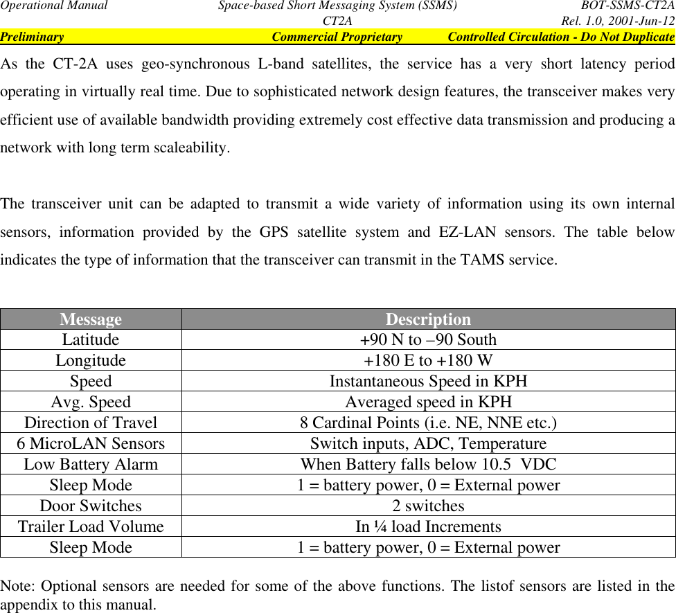
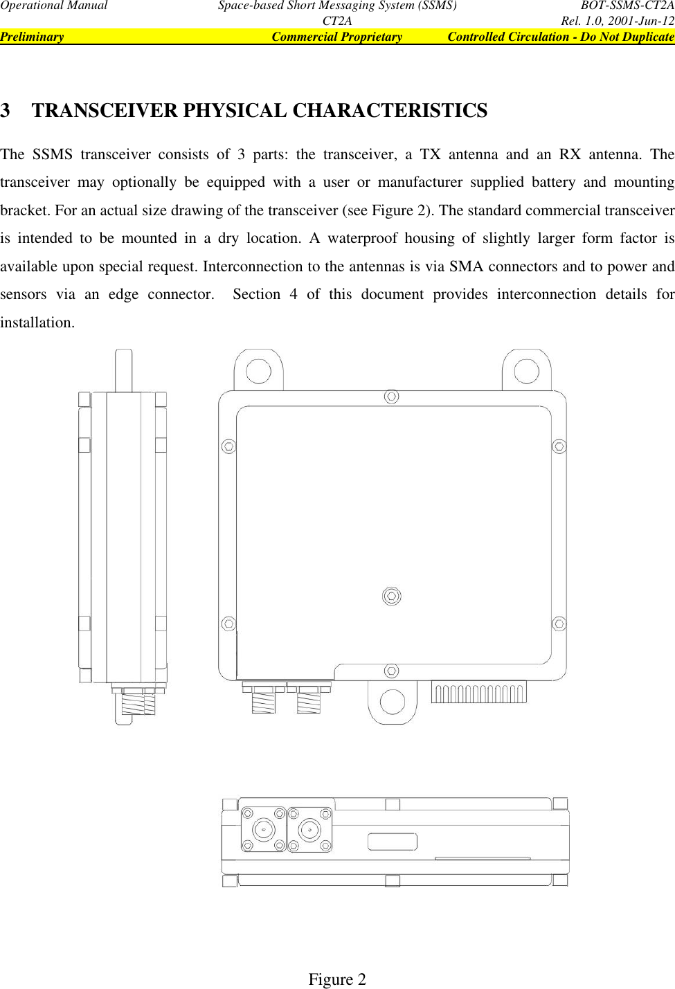
Bot America CT2A L-Band Transceiver with GPS Reciever User Manual Exhibit 11 SSMS Manual

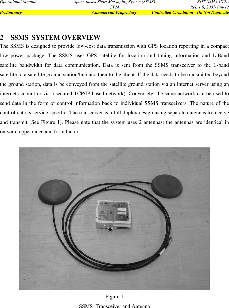
BotCorp America L-Band Transceiver with GPS Reciever Exhibit 11 SSMS Manual

manual

BOTCORP AMERICA  Release  1.0June 12,  2001Operational Manualfor theSpace-based Short Message System Terminal (SSMS)Model CT2A
Operational Manual Space-based Short Messaging System (SSMS) BOT-SSMS-CT2ACT2A Rel. 1.0, 2001-Jun-12Preliminary Commercial Proprietary Controlled Circulation - Do Not Duplicate- i -DisclaimerNeither  Botcorp America nor Mobilacomm (a division of Botcorp America) are responsible for theaccuracy of the statements made or opinions expressed in this publication and neither Botcorp Americanor Mobilacomm nor the author assumes liability with respect to any damages or loss incurred as a resultof the use of the information contained in this publication. Neither Botcorp America nor Mobilacommmakes any representations in regards to the current licensing status of services using the SSMS terminal.For current information please consult the relevant licensing body.Copyright NoticeThis document contains proprietary intellectual property and confidential information. Dissemination ofthe information contained in this document to a Third Party, by whatever means and in whatever form,for example by copying, reproduction in any form, direct distribution of original documents, requireswritten approval from Botcorp America/Mobilacomm.
Operational Manual Space-based Short Messaging System (SSMS) BOT-SSMS-CT2ACT2A Rel. 1.0, 2001-Jun-12Preliminary Commercial Proprietary Controlled Circulation - Do Not Duplicate- ii -Contacting the ManufacturerBotCor America/MobilacommTechnical SupportAddress: 775 Main Street, Suite # 230Buffalo, New York, U.SA. 14203Telephone: 716 842 1033Fax: 76 842 1025E-Mail: Chris_Rampen@Botcorp.comBusiness Hours: Monday-Friday, 9:00 – 17:00Eastern Standard Time
Operational Manual Space-based Short Messaging System (SSMS) BOT-SSMS-CT2ACT2A Rel. 1.0, 2001-Jun-12Preliminary Commercial Proprietary Controlled Circulation - Do Not Duplicate- iii -AcknowledgmentsThis document was prepared by BOTCORP America.1. Prepared by: Chris RampenSpecial ProjectsBot Engineering Ltd.2. Proofed by: Barbara PrescottEditorBot Engineering Ltd.3. Engineering Review by: Roger P. BotVice PresidentBot Engineering Ltd.4. Approved by: David L. BotPresidentBot Engineering Ltd.DistributionDocument Issued by: C. Rampen Purpose: Technical SupportDistribution Media: Hard Copy Restrictions: Distribution List OnlyMS Word ’97 File Positive Recall: NoOriginating Organization(s) Receiving Organization(s)BotCorp America    General – NDA RequiredC. Rampen
Operational Manual Space-based Short Messaging System (SSMS) BOT-SSMS-CT2ACT2A Rel. 1.0, 2001-Jun-12Preliminary Commercial Proprietary Controlled Circulation - Do Not Duplicate- iv -Document Release HistoryRelease Date Description1.0 Draft-1 2000-Nov-19 Preliminary Draft1.0 Draft-2 2000-Dec-6 Revised Draft1.0 Draft-3 2001-Apr-2 Revised Draft1.0 Draft-4 2001-Apr-22 Revised Draft1.0 2001-Jun-12 Release
Operational Manual Space-based Short Messaging System (SSMS) BOT-SSMS-CT2ACT2A Rel. 1.0, 2001-Jun-12Preliminary Commercial Proprietary Controlled Circulation - Do Not Duplicate- v -Table of Contents1SCOPE ................................................................................................................................................................ 11.1 MODEL  NOMENCLATURE.................................................................................................................... 12SSMS  SYSTEM OVERVIEW ......................................................................................................................... 23TRANSCEIVER PHYSICAL CHARACTERISTICS.................................................................................... 43.1 MODES OF OPERATION (TAMS)........................................................................................................... 53.2 SENSOR INPUTS....................................................................................................................................... 63.3 SSMS SYSTEM LIMITATIONS/WARNINGS......................................................................................... 64CT-2A TERMINAL INSTALLATION AND TESTING................................................................................ 74.1 CT-2A TRANSCEIVER   KIT CONTENTS.............................................................................................. 74.2 BATTERY CONSIDERATIONS............................................................................................................... 74.3 ANTENNA  MOUNTING  AND INSTALLATION.................................................................................. 84.4 TRANSCEIVER  MOUNTING  AND  INSTALLATION ........................................................................ 84.5 EXTERNAL  SENSOR  DESCRIPTION  AND INSTALLATION........................................................... 94.5.1 Wiring Specifics................................................................................................................................ 104.5.2 Sensor Allocation to Return Link Message....................................................................................... 114.6 STEP BY STEP SYSTEM SETUP........................................................................................................... 145TROUBLE SHOOTING.................................................................................................................................. 17APPENDICESAppendix A: Specifications
Operational Manual Space-based Short Messaging System (SSMS) BOT-SSMS-CT2ACT2A Rel. 1.0, 2001-Jun-12Preliminary Commercial Proprietary Controlled Circulation - Do Not Duplicate1 SCOPEThis document is intended to provide specific information required to install and operate the Space-basedShort Message System (SSMS) Terminal (Model CT2A). Variations in SSMS functionality aredependant on the service subscribed to. This manual is intended to be as generic to all SSMS variants(Model CT-2A-(xxx)) as possible; for additional service specific information, please contact the serviceprovider in your region as indicated in Appendix C. Please note that this manual does not make anyrepresentations about the current licensing status of services using the SSMS terminal. For currentinformation please consult the relevant licensing body as well as the listed service providers.1.1 MODEL  NOMENCLATUREAs the CT-2A-(xxx) transceiver can be configured to accommodate different services in different regionsover different satellite systems, an identifier has been included in the model designation to describe theexact transceiver configuration. For example, the transceiver used for TMI communications TAMs (trackand manage service) is identified as ‘CT-2A-TAMs’. The transceiver used for SpaceChecker’s Service isidentified as ‘CT2A-SC’.
Operational Manual Space-based Short Messaging System (SSMS) BOT-SSMS-CT2ACT2A Rel. 1.0, 2001-Jun-12Preliminary Commercial Proprietary Controlled Circulation - Do Not Duplicate2 SSMS  SYSTEM OVERVIEWThe SSMS is designed to provide low-cost data transmission with GPS location reporting in a compactlow power package. The SSMS uses GPS satellite for location and timing information and L-Bandsatellite bandwidth for data communication. Data is sent from the SSMS transceiver to the L-bandsatellite to a satellite ground station/hub and then to the client. If the data needs to be transmitted beyondthe ground station, data is be conveyed from the satellite ground station via an internet server using aninternet account or via a secured TCP/IP based network). Conversely, the same network can be used tosend data in the form of control information back to individual SSMS transceivers. The nature of thecontrol data is service specific. The transceiver is a full duplex design using separate antennas to receiveand transmit (See Figure 1). Please note that the system uses 2 antennas: the antennas are identical inoutward appearance and form factor.Figure 1SSMS  Transceiver and Antenna
Operational Manual Space-based Short Messaging System (SSMS) BOT-SSMS-CT2ACT2A Rel. 1.0, 2001-Jun-12Preliminary Commercial Proprietary Controlled Circulation - Do Not DuplicateAs the CT-2A uses geo-synchronous L-band satellites, the service has a very short latency periodoperating in virtually real time. Due to sophisticated network design features, the transceiver makes veryefficient use of available bandwidth providing extremely cost effective data transmission and producing anetwork with long term scaleability.The transceiver unit can be adapted to transmit a wide variety of information using its own internalsensors, information provided by the GPS satellite system and EZ-LAN sensors. The table belowindicates the type of information that the transceiver can transmit in the TAMS service.Message DescriptionLatitude +90 N to –90 SouthLongitude +180 E to +180 WSpeed Instantaneous Speed in KPHAvg. Speed Averaged speed in KPHDirection of Travel 8 Cardinal Points (i.e. NE, NNE etc.)6 MicroLAN Sensors Switch inputs, ADC, TemperatureLow Battery Alarm When Battery falls below 10.5  VDCSleep Mode 1 = battery power, 0 = External powerDoor Switches 2 switchesTrailer Load Volume In ¼ load IncrementsSleep Mode 1 = battery power, 0 = External powerNote: Optional sensors are needed for some of the above functions. The listof sensors are listed in theappendix to this manual.
Operational Manual Space-based Short Messaging System (SSMS) BOT-SSMS-CT2ACT2A Rel. 1.0, 2001-Jun-12Preliminary Commercial Proprietary Controlled Circulation - Do Not Duplicate3 TRANSCEIVER PHYSICAL CHARACTERISTICSThe SSMS transceiver consists of 3 parts: the transceiver, a TX antenna and an RX antenna. Thetransceiver may optionally be equipped with a user or manufacturer supplied battery and mountingbracket. For an actual size drawing of the transceiver (see Figure 2). The standard commercial transceiveris intended to be mounted in a dry location. A waterproof housing of slightly larger form factor isavailable upon special request. Interconnection to the antennas is via SMA connectors and to power andsensors via an edge connector.  Section 4 of this document provides interconnection details forinstallation.Figure 2
Operational Manual Space-based Short Messaging System (SSMS) BOT-SSMS-CT2ACT2A Rel. 1.0, 2001-Jun-12Preliminary Commercial Proprietary Controlled Circulation - Do Not Duplicate3.1 MODES OF OPERATIONThe transceiver transmits data according to three possible modes:• Scheduled ReportingThe transceiver is designed to transmit data according to a programmed schedule. This could beevery 15 minutes or up to once a day depending on the type of subscription provided and the servicesoffered by the service provider.• Event ResponseThe transceiver will transmit when a critical sensor alarm point is exceeded or when other internalset points are triggered. As an example of an internal set point trigger, the transceiver could beconfigured to transmit data when the unit goes from ‘ready’ mode to ‘sleep’ mode. Sensor limits areset using optional EZ-LAN support software.• User RequestData from the transceiver can be retrieved via a user-generated request via the internet interface.The SSMS Terminal features a ‘sleep’ mode when it is running on battery power. When in ‘sleep’ mode,the SSMS will wake itself up according to the schedule and transmit its report. When in the ‘sleep’ mode,the SSMS will also wake itself up at increments (depending on the subscription and service provider) ofthe scheduled transmission time and look for – and if necessary respond to -event responses and polls.Consequently, transceivers that are polled when in sleep mode will transmit with a delay dependant onthe type of service to which the unit is subscribed. For exact times please consult your service provider.The ‘wake-up’ intervals are determined by the subscription type and is set by the service provider.The transceiver has an additional battery saving mode that is activated when the battery drops below10VDC. This function is designed to prevent battery damage caused by deep discharging the battery.
Operational Manual Space-based Short Messaging System (SSMS) BOT-SSMS-CT2ACT2A Rel. 1.0, 2001-Jun-12Preliminary Commercial Proprietary Controlled Circulation - Do Not Duplicate3.2 SENSOR INPUTSExternal sensing is accomplished through EZ-LAN sensors. EZ-LAN employs simple twisted-paircabling and inexpensive one-wire sensors. Each sensor has a unique Network Address code therebyallowing all devices to operate in parallel over a single twisted pair. The number of sensors that theSSMS transceiver can accommodate is determined by the service and installation specifications (Type ofSensor used, length of run, etc.). All sensor inputs to the transceiver are via the EZ-LAN buss.3.3 SSMS SYSTEM LIMITATIONS/WARNINGSThe SSMS transceiver requires a line of sight view of the satellite for a sufficiently long period togenerate GPS and L-band lock. As a result, if mission critical applications are envisioned, severalprecautions must be taken to ensure real-time communications capability, The user is urged to request thedocument GUIDELINES FOR DEPLOYMENT OF SSMS IN MISSION CRITICAL APPLICATIONS.Doc# SC-CT2A-CN-1. The TAMS service is intended as a commercial mobile asset management systemand, as a result, rather simple installation guidelines can be followed as indicated in the sections thatfollow.The SSMS transceiver is a low power RF device and is subject to health considerations as are all devicesof this type. Although the device is of relatively low power and transmits for only brief burst (typicallyless than 1 second), it is not recommended that the antenna be placed in close proximity (less than 18”) tohuman beings for extended periods of time. Consequently, the transceiver and antennas must be properlyinstalled before operation (See Section 4.3 Antenna Mounting and Installation). A RF Radiation Exposure Evaluation Report for this device is available upon request under Doc# SC-CT2A-RFREP-1.The SSMS transceiver and antennas have been qualified for use over the temperature range of –30 to+55C. The unit utilizes a unique self-calibrating function where the units carries out continuous self-calibration of critical operational parameters thereby ensuring reliable operation under all thermal;conditions. The unit also utilizes an over temperature shutdown circuit where operation above 80C isinhibited.
Operational Manual Space-based Short Messaging System (SSMS) BOT-SSMS-CT2ACT2A Rel. 1.0, 2001-Jun-12Preliminary Commercial Proprietary Controlled Circulation - Do Not Duplicate4 CT-2A TERMINAL INSTALLATION AND TESTING4.1 CT-2A TRANSCEIVER   KIT CONTENTSThe basic kit contains the following items:• Antenna with integral connecting cable• Transceiver unit• Power/Sensor connecting cable• InstructionsAdditional items that may be obtained are:• EZ-LAN Temperature, Motion, A/D converters and Door Sensors• Waterproof Housing for Transceiver• Antenna Mounting Kits4.2 BATTERY CONSIDERATIONSAs implied above, the transceiver kit is not supplied with an external battery. This is the direct result ofhazardous materials shipping regulations, battery aging and lifetime considerations. The transceiver isdesigned to operate from two types of power supplies: main and backup. The transceiver operatesdifferently depending on which supply is being used to supply power. If the unit is operating from mainpower (e.g, an uninterruptible power supply - such as a battery being continuously charged by aalternator) the transceiver will operate continuously, receiving both GPS and satellite data.In applications where main power is not available or is intermittently available, the transceiver makes useof power saving features. In these applications, when main power is not available the transceiver onlydraws significant power when making scheduled transmissions; when the unit is not transmitting the unitenters a very low power mode. The exact timetable is configurable to provide the best compromisebetween power savings and reporting frequency.Typical vehicular applications use both main and backup supplies. This provides optimum performancewhen vehicle power is available and still provides the needed reporting capabilities when the vehicle’scharging circuit is not operational.  In general, the main supply consists of the vehiclepower (+12V in North America) and a +12v battery for the backup power. The backup battery is
Operational Manual Space-based Short Messaging System (SSMS) BOT-SSMS-CT2ACT2A Rel. 1.0, 2001-Jun-12Preliminary Commercial Proprietary Controlled Circulation - Do Not Duplicateautomatically charged from the vehicle power using circuitry which is internal to the transceiver. In orderto meet specific user requirements, the backup power supply battery must be sized to match the eventtimetable and the required backup battery life. In the event that the battery voltage of the main andbackup battery reaches the battery endpoint voltage (typically 10V), the unit disconnects from the batterysource and inhibits all further transceiver operation until voltage is restored to usable levels. While anumber of battery chemistries can be used with the transceiver, lead acid, gel electrolyte have beendetermined to provide the best compromise between cost, capacity and low temperature operation.In order to size the 12V(nominal) backup battery an equation must be applied as follows:battery capacity in Amp/Hrs = anticipated non-charge period in days  X .05 X  # of reports per day4.3 ANTENNA  MOUNTING  AND INSTALLATIONThe antennas is designed to be mounted on top of a mobile platform such as a trailer, vehicle roof ormast. The antennas should be mounted 1m (3’) apart with a clear shot at the sky and no obstructions inthe antenna’s field of view. Failure to obtain a lock on the service providing or GPS satellites indicatesan inappropriate mounting position..The antenna can be mounted with the double-sided tape, epoxy or a urethane adhesive. The connectingwire should be secured at 20cm (approx. 10”) intervals using cable clamps. It is important that theantenna mounting method withstand any foreseeable wind loading and is not in proximity (18”) to humanbeings for prolonged periods of time.4.4 TRANSCEIVER   MOUNTING  AND  INSTALLATIONThe transceiver is to be mounted inside. It is advisable that the unit be secured using the shock mountsincorporated into the transceiver. Figure 1. shows  the mounting hole arrangement. A ‘drip loop’ shouldbe used for the antenna cable to transceiver connection so that any condensate that might accumulate onthe cable does not flow into the connector. The transceiver is provided with a 6ft power/sensorconnecting cable.The cable consist of 3 twisted pair groups (e.g. 6 Wires). The cable should be wired according to thefollowing color coding:
Operational Manual Space-based Short Messaging System (SSMS) BOT-SSMS-CT2ACT2A Rel. 1.0, 2001-Jun-12Preliminary Commercial Proprietary Controlled Circulation - Do Not DuplicatePair Color Function/Description1Black GroundGreen EZLAN 1 wire sensor input – paired with Black ground wire2Black GroundRed Backup Battery + 12VDC – Charged from Main supply3Black GroundWhite Main supply  + 12VDC – transmits when voltage changes 0-12VDC or 12-0VDCNote: all grounds should go to a common point. A good vehicle chassis ground is essential for reliable operation.The transceiver is reverse polarity protected and will not operate if the power +/Ground connections are reversed.If desired, an external 5A fuses may be used if needed for vehicle protection against shorts in the power cable. Thetransceiver unit is protected by internal resettable fuses. If the internal protective fuse trips, it may take a fewminutes before the fuses reset.The user may also supply an edge connector to facilitate interconnect with the terminal. In this case theuser is responsible to ensure that the wire connections are correctly matched to the connector . Theconnector designation and recommended wire color is as follows:A1-RESERVED              B1-RESERVEDA2-RESERVED             B2- RESERVEDA3-RESERVED             B3- +12v MAIN (White)A4-RESERVED              B4-+12v MAIN  (White)A5-RESERVED              B5- GND (BLACK)A6-RESERVED             B6- GND (BLACK)A7-RESERVED             B7- +12 BACKUP (Red)A8-RESERVED             B8- +12 BACKUP (Red)A9-RESERVED             B9- RESERVEDA10- RESERVED           B10- EZLAN (Green)Note: the reserved connections are used for non-TAMS applications.4.5 EXTERNAL  SENSOR  DESCRIPTION  AND INSTALLATIONThe EZ_LAN is a low-cost and highly reliable method of connecting sensors to micro-controller basedequipment. The connection is via twisted pair wires: one for sense and one for ‘return’ or ground. Thesensors use the conventional EZ-LAN protocol where less than 0.8 V indicates a logic zero and greaterthan 2.2V indicates a logic ‘1’. Sensors are identified by a unique internal 48 bit number that is laserconfigured into the sensors. The sensors are extremely low power and are powered entirely from thetwisted pair wires.
Operational Manual Space-based Short Messaging System (SSMS) BOT-SSMS-CT2ACT2A Rel. 1.0, 2001-Jun-12Preliminary Commercial Proprietary Controlled Circulation - Do Not DuplicateThe SSMS-TAMS Transceiver currently supports three types of EZ-LAN EZ-LAN sensors: DigitalThermometer, Dual Addressable Switch, and Quad A/D Converte. As an A/D converter is supportedalmost any sensor potentially can be adapted to work with the transceiver. The Digital Thermometersupports a single temperature channel that can measure temperatures from -55 °C to 125 °C in 0.5 °Cincrements.The Dual Addressable Switch supports two channels. Each channel possesses a current state bit plus anactivity latch bit. The activity latch bit can be used to determine whether the switch has changed statefrom the last time the switch was read.The Quad A/D Converter supports four high-impedance inputs with programmable input ranges of 2.56Vor 5.12 volts and resolutions of 1 to 16 bits.Sensors are provided with detailed installation instructions. These instructions are available atwww.mobilacomm.com.4.5.1  Wiring SpecificsFor short runs (<30m or 60’ approximately) the sensors may be connected using standard twisted-pair(e.g. telephone) cable. For longer runs, or when sensors do not function correctly it is recommended thatCategory 5, twisted-pair (typical capacitance 50 pF/m) be used. The cabling must be twisted pair, parallelwires are not acceptable due to the susceptibility to inductive coupling from EMF sources. It isacceptable to utilize shielded cable but the capacitance restrictions shown above should be observed.Sensors are connected in parallel as per Figure 3.  The TAMS Service will accommodate a maximum of6 sensors. The transceiver auto-senses the type of sensor and replaces appropriate bits in the report’stemperature payload section with the appropriate sensor data .It is important to connect the sensor in the correct orientation (e.g ground to ground, sense to sense).Failure to do so will not affect the transceiver but may damage the sensor.SENSEOptionalDiode
Operational Manual Space-based Short Messaging System (SSMS) BOT-SSMS-CT2ACT2A Rel. 1.0, 2001-Jun-12Preliminary Commercial Proprietary Controlled Circulation - Do Not DuplicateSensor 1Figure 3MicroLAN Connection ExampleIf runs of greater than 100m are anticipated, the cable end should be terminated using a Schottky diode(i.e  1N5819). The cathode side (band end) of the diode should be connected to the sense line, the anodeto the ground line.For application notes regarding EZ-LAN connection please refer to the “EZ-LAN design Guide”. Thisdocument is available at the Mobilacomm Website.4.5.2  Sensor Allocation to Return Link MessageThe return link message consists of 15 bytes. The bits allocated to returning EZ-LAN sensor informationstart at byte 8 and are illustrated by the following table (the blank cells represent data not directlyassociated with the EZ-LAN Sensors and are not discussed here) :Byte Bit 7 Bit 6 Bit 5 Bit 4 Bit 3 Bit 2 Bit 1 Bit 08DA MA9RRRRR R10 RRRRRRR R11 RRRRRRR R12 R RThe “DA” and the “MA” bits in byte 8, are the Door Alarm and the Motion Alarm bits respectively.  Thefirst Dual Switch is always allocated to servicing the Door Alarm and Motion Alarm bits.The state of the Door Alarm (DA) is determined by the current state and the activity latch  state ofchannel A on the first Dual Switch found on the 1- Wire Bus.  The Door Alarm State as a function of thecurrent state and activity latch is illustrated by the following truth table:Door Alarm Activity Latch Door State0 0 01 1 01 0 1RETURN
Operational Manual Space-based Short Messaging System (SSMS) BOT-SSMS-CT2ACT2A Rel. 1.0, 2001-Jun-12Preliminary Commercial Proprietary Controlled Circulation - Do Not Duplicate1 1 1Where an Activity Latch of 0 indicates the sensor has not changed since it was last read and a Door Stateof 1 indicates the door is open. The state of the Motion Alarm is determined solely by the state of theactivity latch on channel B of the first Dual Switch found on the EZ-LAN Bus. In other words, if the stateof channel B is different from the last time is was read then the Motion Alarm bit is set to 1. If has notchanged since the last time it was read then it is set to 0. The 24  bits identified as “R”, the Report Bits, in bytes 9 through 12 of the return link message are allocated based on which sensors appear on the EZ-LAN Bus. The number of Report Bits allocated per sensor type and the format of the respective bits areas follows. For temperature sensors, 4 bits are allocated, with the value of the bits representing thefollowing temperatures.Value Temp. ° C Temp. ° F0<= -13 <=8.61–11 12.22-9 15.83–7 19.44–5 235–3 26.66–1 30.27 1 33.88 3 37.49 5 4110 7 44,611 9 48.212 11 51.813 13 55.414 >= 15 5915 Error ErrorFor Dual switches, 2 bits are allocated with the left bit representing the current state of channel B and theright bit representing the current state of channel A.For A/D Converters, 8 bits are allocated per channel except in the special case where 4 separate A/DConverters are present on the EZ-LAN Bus.  When 4 A/D Converters are present on the EZ-LAN Bus, 8-bits are allocated to the first two A/D converters and 4 bits are allocated to each of the last two A/Dconverters.The rules for the allocation of the 24 Reports Bits based on sensor type are summarized as follows:
Operational Manual Space-based Short Messaging System (SSMS) BOT-SSMS-CT2ACT2A Rel. 1.0, 2001-Jun-12Preliminary Commercial Proprietary Controlled Circulation - Do Not Duplicate1. Temperature sensors are the highest priority for allocation, followed by Dual Switches and then byA/D Converters. Remember that the first Dual switch is always allocated to servicing the Door Alarmand Motion Alarm so you need al least two Dual switches, before any of the 24 Report bits areallocated to a Dual switch.2. If there is there is one A/D Converter, after allocating bits for Temperatures sensors and DualSwitches, as many channels as bits available for that A/D Converter are allocated. For example, ifthere was only one A/D converter on the EZ-LAN Bus (and no other sensors) then 8 bits would beallocated for the first three channels of the one A/D Converter.3. If there is  more than one A/D Converter and less than 4 A/D Converters, after allocating bits forTemperature sensors and Dual Switches, 8 bits are allocated for the first channel of each A/DConverter.4. If there are only 4 A/D Converters on the EZ-LAN Bus, 8-bits are allocated for the first channel ofthe first two A/D Converters and then 4 bits are allocated for each for the first channels of each of theother two A/D Converters.The effect of these allocation rules on the format of the return link message is demonstrated by thefollowing examples:Example 1The EZ-LAN Bus has 6 Temperature sensors (T1-T6) only. The return link message bits are allocated asbelow:Byte Bit 7 Bit 6 Bit 5 Bit 4 Bit 3 Bit 2 Bit 1 Bit 09T1 T1 T1 T1 T2 T210 T2 T2 T3 T3 T3 T3 T4 T411 T4 T4 T5 T5 T5 T5 T6 T612 T6 T6
Operational Manual Space-based Short Messaging System (SSMS) BOT-SSMS-CT2ACT2A Rel. 1.0, 2001-Jun-12Preliminary Commercial Proprietary Controlled Circulation - Do Not DuplicateExample 2The EZ-LAN Bus has 1 Temperature Sensor  (T1), 3 Dual Switches (D1-D3), and two A/D converters(A1, A2). The return link message bits are allocated as below:Byte Bit 7 Bit 6 Bit 5 Bit 4 Bit 3 Bit 2 Bit 1 Bit 08D1 D19T1 T1 T1 T1 D2 D210 D3 D3 A1 A1 A1 A1 A1 A111 A1 A1 A2 A2 A2 A2 A2 A212 A2 A2Example 3The EZ-LAN Bus has 2 Temperature Sensors (T1, T2) and one A/D Converter (A1-0 is channel 0., A1-1is channel 1 on the same A/D converter). The return link message bits are allocated as below:Byte Bit 7 Bit 6 Bit 5 Bit 4 Bit 3 Bit 2 Bit 1 Bit 09T1 T1 T1 T1 T2 T210 T2 T2 A1-0 A1-0 A1-0 A1-0 A1-0 A1-011 A1-0 A1-0 A1-1 A1-1 A1-1 A1-1 A1-1 A1-112 A1-1 A-1Example 4The EZ-LAN Bus has 4 A/D Converters only (A1-A4). The return link message bits are allocated asbelow:Byte Bit 7 Bit 6 Bit 5 Bit 4 Bit 3 Bit 2 Bit 1 Bit 09A1 A1 A1 A1 A1 A110 A1 A1 A2 A2 A2 A2 A2 A211 A2 A2 A3 A3 A3 A3 A4 A412 A4 A44.6 STEP BY STEP SYSTEM SETUPA.  Connect Main Power and optional backup power, using the color codes identified previously.B.  Attach RX and TX antennas to the SMA connectors as indicated on the housing. For quick reference
Operational Manual Space-based Short Messaging System (SSMS) BOT-SSMS-CT2ACT2A Rel. 1.0, 2001-Jun-12Preliminary Commercial Proprietary Controlled Circulation - Do Not Duplicatethe TX antenna, connector is located closest to the edge of the housing. IF THE ANTENNAS AREREVERSED, THE UNIT WILL NOT OPERATE.C.  With the successful completion of the above steps the LED indicator will demonstrate the followingbehavior:    The green LED on the transceiver indicates the unit’s status during start-up and transmission. Whenthe transceiver is in the sleep mode the status LED is turned off to conserve power.    When the transceiver is initially powered up check that the unit gives the following indications in thefollowing order:1.  LED Solid    Transceiver has power but has not locked to either the GPS or service providing satellites2.  LED blinks once per second    Transceiver is locking on to the service providing satellite. Note that the transceiver may lock onto either satellite type depending on which signal the transceiver finds first (i.e Indications 3. Mayprecede 2). The time the transceiver takes to lock onto a satellite is variable – expect 1-10 minutes.3.  LED blinks once every 2 seconds    Transceiver is locking on to GPS satellite.4.  LED goes off    Transceiver has locked onto both satellites5.  LED blinks once per installed sensor.    The transceiver will blink once per installed sensor to a maximum of 6 blinks (TAMS Service).This is a system check of the sensors functionality and occurs prior to transmission (expect 1-2minutes after the LED has gone off).6.  LED gives 3 fast blinks    The transceiver is about to transmit.7.  LED gives 5 fast blinks    Transmission is successful.8.  LED gives 10 fast blinks    Transmission failed.      This cycle should be completed within 10 minutes when the unit is first powered up. The unit willthen transmit according to the service that the unit has been subscribed to. The time required tocomplete a transmission cycle should be considerably reduced from the initial power up cycle.Variations in cycle time are dependent on the unit’s ability to lock to either of the satellites.D. After transmission has been successfully completed, the internet account should be checked to verifythe units operation. Sensor functionality should be checked at this time. A reading of 127º indicatesthat a sensor is not connected or is not being read. IN THE EVENT THAT A TRANSMISSION DID
Operational Manual Space-based Short Messaging System (SSMS) BOT-SSMS-CT2ACT2A Rel. 1.0, 2001-Jun-12Preliminary Commercial Proprietary Controlled Circulation - Do Not DuplicateNOT OCCCUR, THE LED BLINK SEQUENCE MAY BE USED TO DETERMINE THE LIKELYCAUSE AS INDICATED IN THE FOLLOWING TABLE.E.   Note that during first start up, main power MUST be applied to the transceiver, failing to do so willresult in the unit immediately entering low power mode without a obtaining a clock calibration. Inthis case, the unit will miss the next timetable event during which correct timing will be restored andnormal timetable events executed.
Operational Manual Space-based Short Messaging System (SSMS) BOT-SSMS-CT2ACT2A Rel. 1.0, 2001-Jun-12Preliminary Commercial Proprietary Controlled Circulation - Do Not Duplicate5 TROUBLE SHOOTINGThe table below describes the status indication. LED Indicator ServiceSatellite GPSSatellite TransceiverFunctionSolid Blocked Blocked NoneBlinks (1s on, 1s off) Blocked Available NoneBlinks (2s on, 2s off) Available Blocked NoneOff Available Available Ready1 fast Blink per sensor (Max. 6) Available Available Sensor Check3 Fast Blinks Available Available About to transmit5 Fast Blinks Available Available Transmit OK.10 Fast Blinks Indeterminate Indeterminate Transmit Failed
Operational Manual Space-based Short Messaging System (SSMS) BOT-SSMS-CT2ACT2A Rel. 1.0, 2001-Jun-12Preliminary Commercial Proprietary Controlled Circulation - Do Not Duplicate- A1 -Appendix  ASPECIFICATIONS
Operational Manual Space-based Short Messaging System (SSMS) BOT-SSMS-CT2ACT2A Rel. 1.0, 2001-Jun-12Preliminary Commercial Proprietary Controlled Circulation - Do Not DuplicateSpecifications                      DescriptionPower Source 10.0 – 18 VDC (external – battery supplied by end-user)Power Consumption Transmit Mode 2.5 A      (<1 second bursts) Receive Mode 200 mA  (Standby mode when not on battery power)   Sleep Mode 1 mA      (When on battery power)   Battery Saving Mode 100 uA   (When battery voltage drops below 10.5VDC)Positional Accuracy   Horizontal <10 meters RMS (without SA)   Vertical <25 meters RMS (without SA)   Velocity 0.2 mile/hour RMS (0.2 meter/sec RMS) between 10 and 950 mphconstant velocity)Satellite Lock Times   Hot Start 30 seconds, typical(Same location, last fix less than 4 hours, no removal of power)   Warm start 1 minute, typical(no removal of power)   Cold start: 2.5 minutes typical(power removed)Sensors   Type EZ-LAN type (sense line and return). Sensor power is external (viaconnection) 0-6V.   Range & Resolution Dependant on Sensors selected – see spec sheet  Operating Voltage EZLAN supply 0-5V: < 0.8V =Logic0 >2.2V=Logic1Environmental Operating -30°C to +55°C, Water Resistant (Not Waterproof) Storage -50°C to +70°C,Physical  Dimensions: Transceiver 11.3cm x 10cm x 3cm (4.45” x 4.0” x 1.10”)  Dimensions: Antennas 11.2cm Dia x 2.0cm (4.5”Dia. x 3/4”)  Weight Transceiver: 290g, Antenna 170g.  Material Antenna: RV stabilized PVC, Transceiver; Passivated Aluminum
Operational Manual Space-based Short Messaging System (SSMS) BOT-SSMS-CT2ACT2A Rel. 1.0, 2001-Jun-12Preliminary Commercial Proprietary Controlled Circulation - Do Not Duplicate

Navigation menu