Bot America CT2A L-Band Transceiver with GPS Reciever User Manual Exhibit 11 SSMS Manual
BotCorp America L-Band Transceiver with GPS Reciever Exhibit 11 SSMS Manual
manual
BOTCORP AMERICA
Release 1.0
June 12, 2001
Operational Manual
for the
Space-based Short Message System Terminal (SSMS)
Model CT2A

Operational Manual Space-based Short Messaging System (SSMS) BOT-SSMS-CT2A
CT2A Rel. 1.0, 2001-Jun-12
Preliminary Commercial Proprietary Controlled Circulation - Do Not Duplicate
- i -
Disclaimer
Neither Botcorp America nor Mobilacomm (a division of Botcorp America) are responsible for the
accuracy of the statements made or opinions expressed in this publication and neither Botcorp America
nor Mobilacomm nor the author assumes liability with respect to any damages or loss incurred as a result
of the use of the information contained in this publication. Neither Botcorp America nor Mobilacomm
makes any representations in regards to the current licensing status of services using the SSMS terminal.
For current information please consult the relevant licensing body.
Copyright Notice
This document contains proprietary intellectual property and confidential information. Dissemination of
the information contained in this document to a Third Party, by whatever means and in whatever form,
for example by copying, reproduction in any form, direct distribution of original documents, requires
written approval from Botcorp America/Mobilacomm.

Operational Manual Space-based Short Messaging System (SSMS) BOT-SSMS-CT2A
CT2A Rel. 1.0, 2001-Jun-12
Preliminary Commercial Proprietary Controlled Circulation - Do Not Duplicate
- ii -
Contacting the Manufacturer
BotCor America/Mobilacomm
Technical Support
Address: 775 Main Street, Suite # 230
Buffalo, New York, U.SA. 14203
Telephone: 716 842 1033
Fax: 76 842 1025
E-Mail: Chris_Rampen@Botcorp.com
Business Hours: Monday-Friday, 9:00 – 17:00
Eastern Standard Time

Operational Manual Space-based Short Messaging System (SSMS) BOT-SSMS-CT2A
CT2A Rel. 1.0, 2001-Jun-12
Preliminary Commercial Proprietary Controlled Circulation - Do Not Duplicate
- iii -
Acknowledgments
This document was prepared by BOTCORP America.
1. Prepared by: Chris Rampen
Special Projects
Bot Engineering Ltd.
2. Proofed by: Barbara Prescott
Editor
Bot Engineering Ltd.
3. Engineering Review by: Roger P. Bot
Vice President
Bot Engineering Ltd.
4. Approved by: David L. Bot
President
Bot Engineering Ltd.
Distribution
Document Issued by: C. Rampen Purpose: Technical Support
Distribution Media: Hard Copy Restrictions: Distribution List Only
MS Word ’97 File Positive Recall: No
Originating Organization(s) Receiving Organization(s)
BotCorp America General – NDA Required
C. Rampen

Operational Manual Space-based Short Messaging System (SSMS) BOT-SSMS-CT2A
CT2A Rel. 1.0, 2001-Jun-12
Preliminary Commercial Proprietary Controlled Circulation - Do Not Duplicate
- iv -
Document Release History
Release Date Description
1.0 Draft-1 2000-Nov-19 Preliminary Draft
1.0 Draft-2 2000-Dec-6 Revised Draft
1.0 Draft-3 2001-Apr-2 Revised Draft
1.0 Draft-4 2001-Apr-22 Revised Draft
1.0 2001-Jun-12 Release

Operational Manual Space-based Short Messaging System (SSMS) BOT-SSMS-CT2A
CT2A Rel. 1.0, 2001-Jun-12
Preliminary Commercial Proprietary Controlled Circulation - Do Not Duplicate
- v -
Table of Contents
1SCOPE ................................................................................................................................................................ 1
1.1 MODEL NOMENCLATURE.................................................................................................................... 1
2SSMS SYSTEM OVERVIEW ......................................................................................................................... 2
3TRANSCEIVER PHYSICAL CHARACTERISTICS.................................................................................... 4
3.1 MODES OF OPERATION (TAMS)........................................................................................................... 5
3.2 SENSOR INPUTS....................................................................................................................................... 6
3.3 SSMS SYSTEM LIMITATIONS/WARNINGS......................................................................................... 6
4CT-2A TERMINAL INSTALLATION AND TESTING................................................................................ 7
4.1 CT-2A TRANSCEIVER KIT CONTENTS.............................................................................................. 7
4.2 BATTERY CONSIDERATIONS............................................................................................................... 7
4.3 ANTENNA MOUNTING AND INSTALLATION.................................................................................. 8
4.4 TRANSCEIVER MOUNTING AND INSTALLATION ........................................................................ 8
4.5 EXTERNAL SENSOR DESCRIPTION AND INSTALLATION........................................................... 9
4.5.1 Wiring Specifics................................................................................................................................ 10
4.5.2 Sensor Allocation to Return Link Message....................................................................................... 11
4.6 STEP BY STEP SYSTEM SETUP........................................................................................................... 14
5TROUBLE SHOOTING.................................................................................................................................. 17
APPENDICES
Appendix A: Specifications

Operational Manual Space-based Short Messaging System (SSMS) BOT-SSMS-CT2A
CT2A Rel. 1.0, 2001-Jun-12
Preliminary Commercial Proprietary Controlled Circulation - Do Not Duplicate
1 SCOPE
This document is intended to provide specific information required to install and operate the Space-based
Short Message System (SSMS) Terminal (Model CT2A). Variations in SSMS functionality are
dependant on the service subscribed to. This manual is intended to be as generic to all SSMS variants
(Model CT-2A-(xxx)) as possible; for additional service specific information, please contact the service
provider in your region as indicated in Appendix C. Please note that this manual does not make any
representations about the current licensing status of services using the SSMS terminal. For current
information please consult the relevant licensing body as well as the listed service providers.
1.1 MODEL NOMENCLATURE
As the CT-2A-(xxx) transceiver can be configured to accommodate different services in different regions
over different satellite systems, an identifier has been included in the model designation to describe the
exact transceiver configuration. For example, the transceiver used for TMI communications TAMs (track
and manage service) is identified as ‘CT-2A-TAMs’. The transceiver used for SpaceChecker’s Service is
identified as ‘CT2A-SC’.
Operational Manual Space-based Short Messaging System (SSMS) BOT-SSMS-CT2A
CT2A Rel. 1.0, 2001-Jun-12
Preliminary Commercial Proprietary Controlled Circulation - Do Not Duplicate
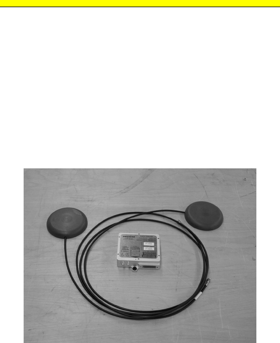
2 SSMS SYSTEM OVERVIEW
The SSMS is designed to provide low-cost data transmission with GPS location reporting in a compact
low power package. The SSMS uses GPS satellite for location and timing information and L-Band
satellite bandwidth for data communication. Data is sent from the SSMS transceiver to the L-band
satellite to a satellite ground station/hub and then to the client. If the data needs to be transmitted beyond
the ground station, data is be conveyed from the satellite ground station via an internet server using an
internet account or via a secured TCP/IP based network). Conversely, the same network can be used to
send data in the form of control information back to individual SSMS transceivers. The nature of the
control data is service specific. The transceiver is a full duplex design using separate antennas to receive
and transmit (See Figure 1). Please note that the system uses 2 antennas: the antennas are identical in
outward appearance and form factor.
Figure 1
SSMS Transceiver and Antenna

Operational Manual Space-based Short Messaging System (SSMS) BOT-SSMS-CT2A
CT2A Rel. 1.0, 2001-Jun-12
Preliminary Commercial Proprietary Controlled Circulation - Do Not Duplicate
As the CT-2A uses geo-synchronous L-band satellites, the service has a very short latency period
operating in virtually real time. Due to sophisticated network design features, the transceiver makes very
efficient use of available bandwidth providing extremely cost effective data transmission and producing a
network with long term scaleability.
The transceiver unit can be adapted to transmit a wide variety of information using its own internal
sensors, information provided by the GPS satellite system and EZ-LAN sensors. The table below
indicates the type of information that the transceiver can transmit in the TAMS service.
Message Description
Latitude +90 N to –90 South
Longitude +180 E to +180 W
Speed Instantaneous Speed in KPH
Avg. Speed Averaged speed in KPH
Direction of Travel 8 Cardinal Points (i.e. NE, NNE etc.)
6 MicroLAN Sensors Switch inputs, ADC, Temperature
Low Battery Alarm When Battery falls below 10.5 VDC
Sleep Mode 1 = battery power, 0 = External power
Door Switches 2 switches
Trailer Load Volume In ¼ load Increments
Sleep Mode 1 = battery power, 0 = External power
Note: Optional sensors are needed for some of the above functions. The listof sensors are listed in the
appendix to this manual.
Operational Manual Space-based Short Messaging System (SSMS) BOT-SSMS-CT2A
CT2A Rel. 1.0, 2001-Jun-12
Preliminary Commercial Proprietary Controlled Circulation - Do Not Duplicate
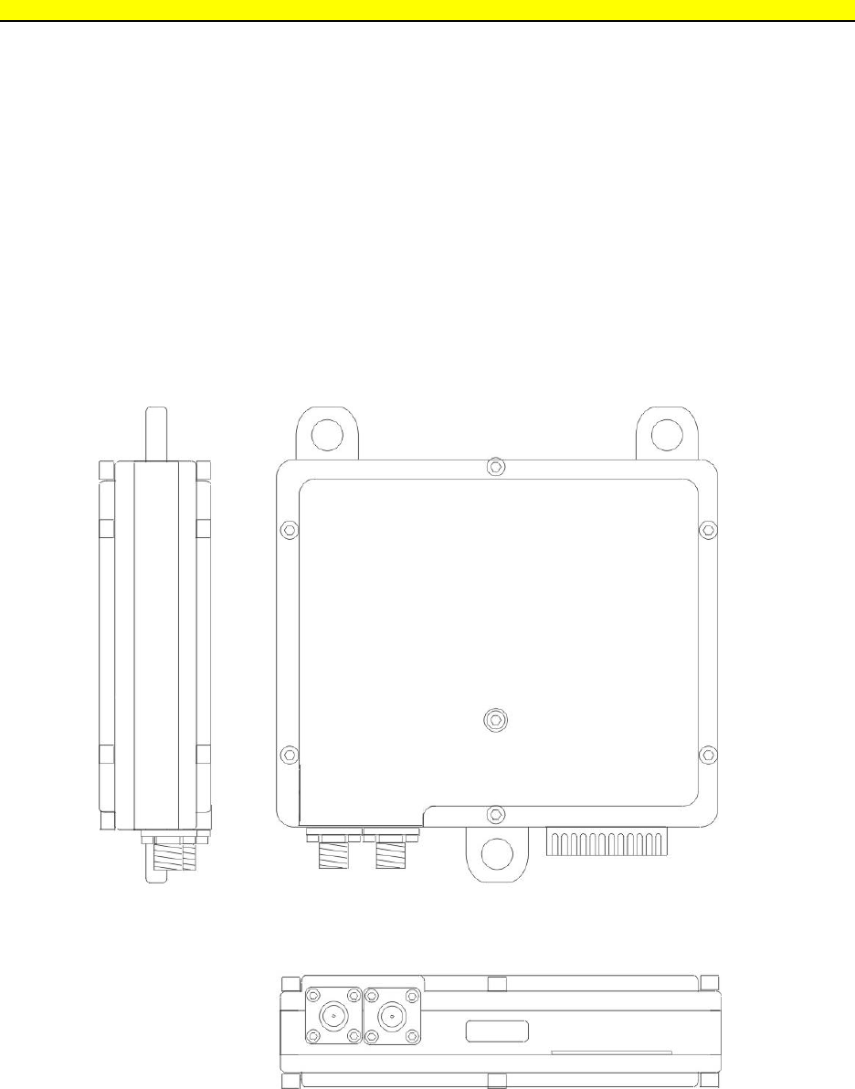
3 TRANSCEIVER PHYSICAL CHARACTERISTICS
The SSMS transceiver consists of 3 parts: the transceiver, a TX antenna and an RX antenna. The
transceiver may optionally be equipped with a user or manufacturer supplied battery and mounting
bracket. For an actual size drawing of the transceiver (see Figure 2). The standard commercial transceiver
is intended to be mounted in a dry location. A waterproof housing of slightly larger form factor is
available upon special request. Interconnection to the antennas is via SMA connectors and to power and
sensors via an edge connector. Section 4 of this document provides interconnection details for
installation.
Figure 2

Operational Manual Space-based Short Messaging System (SSMS) BOT-SSMS-CT2A
CT2A Rel. 1.0, 2001-Jun-12
Preliminary Commercial Proprietary Controlled Circulation - Do Not Duplicate
3.1 MODES OF OPERATION
The transceiver transmits data according to three possible modes:
• Scheduled Reporting
The transceiver is designed to transmit data according to a programmed schedule. This could be
every 15 minutes or up to once a day depending on the type of subscription provided and the services
offered by the service provider.
• Event Response
The transceiver will transmit when a critical sensor alarm point is exceeded or when other internal
set points are triggered. As an example of an internal set point trigger, the transceiver could be
configured to transmit data when the unit goes from ‘ready’ mode to ‘sleep’ mode. Sensor limits are
set using optional EZ-LAN support software.
• User Request
Data from the transceiver can be retrieved via a user-generated request via the internet interface.
The SSMS Terminal features a ‘sleep’ mode when it is running on battery power. When in ‘sleep’ mode,
the SSMS will wake itself up according to the schedule and transmit its report. When in the ‘sleep’ mode,
the SSMS will also wake itself up at increments (depending on the subscription and service provider) of
the scheduled transmission time and look for – and if necessary respond to -event responses and polls.
Consequently, transceivers that are polled when in sleep mode will transmit with a delay dependant on
the type of service to which the unit is subscribed. For exact times please consult your service provider.
The ‘wake-up’ intervals are determined by the subscription type and is set by the service provider.
The transceiver has an additional battery saving mode that is activated when the battery drops below
10VDC. This function is designed to prevent battery damage caused by deep discharging the battery.

Operational Manual Space-based Short Messaging System (SSMS) BOT-SSMS-CT2A
CT2A Rel. 1.0, 2001-Jun-12
Preliminary Commercial Proprietary Controlled Circulation - Do Not Duplicate
3.2 SENSOR INPUTS
External sensing is accomplished through EZ-LAN sensors. EZ-LAN employs simple twisted-pair
cabling and inexpensive one-wire sensors. Each sensor has a unique Network Address code thereby
allowing all devices to operate in parallel over a single twisted pair. The number of sensors that the
SSMS transceiver can accommodate is determined by the service and installation specifications (Type of
Sensor used, length of run, etc.). All sensor inputs to the transceiver are via the EZ-LAN buss.
3.3 SSMS SYSTEM LIMITATIONS/WARNINGS
The SSMS transceiver requires a line of sight view of the satellite for a sufficiently long period to
generate GPS and L-band lock. As a result, if mission critical applications are envisioned, several
precautions must be taken to ensure real-time communications capability, The user is urged to request the
document GUIDELINES FOR DEPLOYMENT OF SSMS IN MISSION CRITICAL APPLICATIONS.
Doc# SC-CT2A-CN-1. The TAMS service is intended as a commercial mobile asset management system
and, as a result, rather simple installation guidelines can be followed as indicated in the sections that
follow.
The SSMS transceiver is a low power RF device and is subject to health considerations as are all devices
of this type. Although the device is of relatively low power and transmits for only brief burst (typically
less than 1 second), it is not recommended that the antenna be placed in close proximity (less than 18”) to
human beings for extended periods of time. Consequently, the transceiver and antennas must be properly
installed before operation (See Section 4.3 Antenna Mounting and Installation).
A RF Radiation Exposure Evaluation Report for this device is available upon request under Doc# SC-
CT2A-RFREP-1.
The SSMS transceiver and antennas have been qualified for use over the temperature range of –30 to
+55C. The unit utilizes a unique self-calibrating function where the units carries out continuous self-
calibration of critical operational parameters thereby ensuring reliable operation under all thermal;
conditions. The unit also utilizes an over temperature shutdown circuit where operation above 80C is
inhibited.

Operational Manual Space-based Short Messaging System (SSMS) BOT-SSMS-CT2A
CT2A Rel. 1.0, 2001-Jun-12
Preliminary Commercial Proprietary Controlled Circulation - Do Not Duplicate
4 CT-2A TERMINAL INSTALLATION AND TESTING
4.1 CT-2A TRANSCEIVER KIT CONTENTS
The basic kit contains the following items:
• Antenna with integral connecting cable
• Transceiver unit
• Power/Sensor connecting cable
• Instructions
Additional items that may be obtained are:
• EZ-LAN Temperature, Motion, A/D converters and Door Sensors
• Waterproof Housing for Transceiver
• Antenna Mounting Kits
4.2 BATTERY CONSIDERATIONS
As implied above, the transceiver kit is not supplied with an external battery. This is the direct result of
hazardous materials shipping regulations, battery aging and lifetime considerations. The transceiver is
designed to operate from two types of power supplies: main and backup. The transceiver operates
differently depending on which supply is being used to supply power. If the unit is operating from main
power (e.g, an uninterruptible power supply - such as a battery being continuously charged by a
alternator) the transceiver will operate continuously, receiving both GPS and satellite data.
In applications where main power is not available or is intermittently available, the transceiver makes use
of power saving features. In these applications, when main power is not available the transceiver only
draws significant power when making scheduled transmissions; when the unit is not transmitting the unit
enters a very low power mode. The exact timetable is configurable to provide the best compromise
between power savings and reporting frequency.
Typical vehicular applications use both main and backup supplies. This provides optimum performance
when vehicle power is available and still provides the needed reporting capabilities when the vehicle’s
charging circuit is not operational. In general, the main supply consists of the vehicle
power (+12V in North America) and a +12v battery for the backup power. The backup battery is

Operational Manual Space-based Short Messaging System (SSMS) BOT-SSMS-CT2A
CT2A Rel. 1.0, 2001-Jun-12
Preliminary Commercial Proprietary Controlled Circulation - Do Not Duplicate
automatically charged from the vehicle power using circuitry which is internal to the transceiver. In order
to meet specific user requirements, the backup power supply battery must be sized to match the event
timetable and the required backup battery life. In the event that the battery voltage of the main and
backup battery reaches the battery endpoint voltage (typically 10V), the unit disconnects from the battery
source and inhibits all further transceiver operation until voltage is restored to usable levels. While a
number of battery chemistries can be used with the transceiver, lead acid, gel electrolyte have been
determined to provide the best compromise between cost, capacity and low temperature operation.
In order to size the 12V(nominal) backup battery an equation must be applied as follows:
battery capacity in Amp/Hrs = anticipated non-charge period in days X .05 X # of reports per day
4.3 ANTENNA MOUNTING AND INSTALLATION
The antennas is designed to be mounted on top of a mobile platform such as a trailer, vehicle roof or
mast. The antennas should be mounted 1m (3’) apart with a clear shot at the sky and no obstructions in
the antenna’s field of view. Failure to obtain a lock on the service providing or GPS satellites indicates
an inappropriate mounting position..
The antenna can be mounted with the double-sided tape, epoxy or a urethane adhesive. The connecting
wire should be secured at 20cm (approx. 10”) intervals using cable clamps. It is important that the
antenna mounting method withstand any foreseeable wind loading and is not in proximity (18”) to human
beings for prolonged periods of time.
4.4 TRANSCEIVER MOUNTING AND INSTALLATION
The transceiver is to be mounted inside. It is advisable that the unit be secured using the shock mounts
incorporated into the transceiver. Figure 1. shows the mounting hole arrangement. A ‘drip loop’ should
be used for the antenna cable to transceiver connection so that any condensate that might accumulate on
the cable does not flow into the connector. The transceiver is provided with a 6ft power/sensor
connecting cable.
The cable consist of 3 twisted pair groups (e.g. 6 Wires). The cable should be wired according to the
following color coding:

Operational Manual Space-based Short Messaging System (SSMS) BOT-SSMS-CT2A
CT2A Rel. 1.0, 2001-Jun-12
Preliminary Commercial Proprietary Controlled Circulation - Do Not Duplicate
Pair Color Function/Description
1Black Ground
Green EZLAN 1 wire sensor input – paired with Black ground wire
2Black Ground
Red Backup Battery + 12VDC – Charged from Main supply
3Black Ground
White Main supply + 12VDC – transmits when voltage changes 0-12VDC or 12-0VDC
Note: all grounds should go to a common point. A good vehicle chassis ground is essential for reliable operation.
The transceiver is reverse polarity protected and will not operate if the power +/Ground connections are reversed.
If desired, an external 5A fuses may be used if needed for vehicle protection against shorts in the power cable. The
transceiver unit is protected by internal resettable fuses. If the internal protective fuse trips, it may take a few
minutes before the fuses reset.
The user may also supply an edge connector to facilitate interconnect with the terminal. In this case the
user is responsible to ensure that the wire connections are correctly matched to the connector . The
connector designation and recommended wire color is as follows:
A1-RESERVED B1-RESERVED
A2-RESERVED B2- RESERVED
A3-RESERVED B3- +12v MAIN (White)
A4-RESERVED B4-+12v MAIN (White)
A5-RESERVED B5- GND (BLACK)
A6-RESERVED B6- GND (BLACK)
A7-RESERVED B7- +12 BACKUP (Red)
A8-RESERVED B8- +12 BACKUP (Red)
A9-RESERVED B9- RESERVED
A10- RESERVED B10- EZLAN (Green)
Note: the reserved connections are used for non-TAMS applications.
4.5 EXTERNAL SENSOR DESCRIPTION AND INSTALLATION
The EZ_LAN is a low-cost and highly reliable method of connecting sensors to micro-controller based
equipment. The connection is via twisted pair wires: one for sense and one for ‘return’ or ground. The
sensors use the conventional EZ-LAN protocol where less than 0.8 V indicates a logic zero and greater
than 2.2V indicates a logic ‘1’. Sensors are identified by a unique internal 48 bit number that is laser
configured into the sensors. The sensors are extremely low power and are powered entirely from the
twisted pair wires.

Operational Manual Space-based Short Messaging System (SSMS) BOT-SSMS-CT2A
CT2A Rel. 1.0, 2001-Jun-12
Preliminary Commercial Proprietary Controlled Circulation - Do Not Duplicate
The SSMS-TAMS Transceiver currently supports three types of EZ-LAN EZ-LAN sensors: Digital
Thermometer, Dual Addressable Switch, and Quad A/D Converte. As an A/D converter is supported
almost any sensor potentially can be adapted to work with the transceiver. The Digital Thermometer
supports a single temperature channel that can measure temperatures from -55 °C to 125 °C in 0.5 °C
increments.
The Dual Addressable Switch supports two channels. Each channel possesses a current state bit plus an
activity latch bit. The activity latch bit can be used to determine whether the switch has changed state
from the last time the switch was read.
The Quad A/D Converter supports four high-impedance inputs with programmable input ranges of 2.56V
or 5.12 volts and resolutions of 1 to 16 bits.
Sensors are provided with detailed installation instructions. These instructions are available at
www.mobilacomm.com.
4.5.1 Wiring Specifics
For short runs (<30m or 60’ approximately) the sensors may be connected using standard twisted-pair
(e.g. telephone) cable. For longer runs, or when sensors do not function correctly it is recommended that
Category 5, twisted-pair (typical capacitance 50 pF/m) be used. The cabling must be twisted pair, parallel
wires are not acceptable due to the susceptibility to inductive coupling from EMF sources. It is
acceptable to utilize shielded cable but the capacitance restrictions shown above should be observed.
Sensors are connected in parallel as per Figure 3. The TAMS Service will accommodate a maximum of
6 sensors. The transceiver auto-senses the type of sensor and replaces appropriate bits in the report’s
temperature payload section with the appropriate sensor data .
It is important to connect the sensor in the correct orientation (e.g ground to ground, sense to sense).
Failure to do so will not affect the transceiver but may damage the sensor.
SENSE
Optional
Diode

Operational Manual Space-based Short Messaging System (SSMS) BOT-SSMS-CT2A
CT2A Rel. 1.0, 2001-Jun-12
Preliminary Commercial Proprietary Controlled Circulation - Do Not Duplicate
Sensor 1
Figure 3
MicroLAN Connection Example
If runs of greater than 100m are anticipated, the cable end should be terminated using a Schottky diode
(i.e 1N5819). The cathode side (band end) of the diode should be connected to the sense line, the anode
to the ground line.
For application notes regarding EZ-LAN connection please refer to the “EZ-LAN design Guide”. This
document is available at the Mobilacomm Website.
4.5.2 Sensor Allocation to Return Link Message
The return link message consists of 15 bytes. The bits allocated to returning EZ-LAN sensor information
start at byte 8 and are illustrated by the following table (the blank cells represent data not directly
associated with the EZ-LAN Sensors and are not discussed here) :
Byte Bit 7 Bit 6 Bit 5 Bit 4 Bit 3 Bit 2 Bit 1 Bit 0
8DA MA
9RRRRR R
10 RRRRRRR R
11 RRRRRRR R
12 R R
The “DA” and the “MA” bits in byte 8, are the Door Alarm and the Motion Alarm bits respectively. The
first Dual Switch is always allocated to servicing the Door Alarm and Motion Alarm bits.
The state of the Door Alarm (DA) is determined by the current state and the activity latch state of
channel A on the first Dual Switch found on the 1- Wire Bus. The Door Alarm State as a function of the
current state and activity latch is illustrated by the following truth table:
Door Alarm Activity Latch Door State
0 0 0
1 1 0
1 0 1
RETURN

Operational Manual Space-based Short Messaging System (SSMS) BOT-SSMS-CT2A
CT2A Rel. 1.0, 2001-Jun-12
Preliminary Commercial Proprietary Controlled Circulation - Do Not Duplicate
1 1 1
Where an Activity Latch of 0 indicates the sensor has not changed since it was last read and a Door State
of 1 indicates the door is open. The state of the Motion Alarm is determined solely by the state of the
activity latch on channel B of the first Dual Switch found on the EZ-LAN Bus. In other words, if the state
of channel B is different from the last time is was read then the Motion Alarm bit is set to 1. If has not
changed since the last time it was read then it is set to 0. The 24 bits identified as “R”, the Report Bits,
in bytes 9 through 12 of the return link message are allocated based on which sensors appear on the EZ-
LAN Bus. The number of Report Bits allocated per sensor type and the format of the respective bits are
as follows. For temperature sensors, 4 bits are allocated, with the value of the bits representing the
following temperatures.
Value Temp. ° C Temp. ° F
0<= -13 <=8.6
1–11 12.2
2-9 15.8
3–7 19.4
4–5 23
5–3 26.6
6–1 30.2
7 1 33.8
8 3 37.4
9 5 41
10 7 44,6
11 9 48.2
12 11 51.8
13 13 55.4
14 >= 15 59
15 Error Error
For Dual switches, 2 bits are allocated with the left bit representing the current state of channel B and the
right bit representing the current state of channel A.
For A/D Converters, 8 bits are allocated per channel except in the special case where 4 separate A/D
Converters are present on the EZ-LAN Bus. When 4 A/D Converters are present on the EZ-LAN Bus, 8-
bits are allocated to the first two A/D converters and 4 bits are allocated to each of the last two A/D
converters.
The rules for the allocation of the 24 Reports Bits based on sensor type are summarized as follows:

Operational Manual Space-based Short Messaging System (SSMS) BOT-SSMS-CT2A
CT2A Rel. 1.0, 2001-Jun-12
Preliminary Commercial Proprietary Controlled Circulation - Do Not Duplicate
1. Temperature sensors are the highest priority for allocation, followed by Dual Switches and then by
A/D Converters. Remember that the first Dual switch is always allocated to servicing the Door Alarm
and Motion Alarm so you need al least two Dual switches, before any of the 24 Report bits are
allocated to a Dual switch.
2. If there is there is one A/D Converter, after allocating bits for Temperatures sensors and Dual
Switches, as many channels as bits available for that A/D Converter are allocated. For example, if
there was only one A/D converter on the EZ-LAN Bus (and no other sensors) then 8 bits would be
allocated for the first three channels of the one A/D Converter.
3. If there is more than one A/D Converter and less than 4 A/D Converters, after allocating bits for
Temperature sensors and Dual Switches, 8 bits are allocated for the first channel of each A/D
Converter.
4. If there are only 4 A/D Converters on the EZ-LAN Bus, 8-bits are allocated for the first channel of
the first two A/D Converters and then 4 bits are allocated for each for the first channels of each of the
other two A/D Converters.
The effect of these allocation rules on the format of the return link message is demonstrated by the
following examples:
Example 1
The EZ-LAN Bus has 6 Temperature sensors (T1-T6) only. The return link message bits are allocated as
below:
Byte Bit 7 Bit 6 Bit 5 Bit 4 Bit 3 Bit 2 Bit 1 Bit 0
9T1 T1 T1 T1 T2 T2
10 T2 T2 T3 T3 T3 T3 T4 T4
11 T4 T4 T5 T5 T5 T5 T6 T6
12 T6 T6

Operational Manual Space-based Short Messaging System (SSMS) BOT-SSMS-CT2A
CT2A Rel. 1.0, 2001-Jun-12
Preliminary Commercial Proprietary Controlled Circulation - Do Not Duplicate
Example 2
The EZ-LAN Bus has 1 Temperature Sensor (T1), 3 Dual Switches (D1-D3), and two A/D converters
(A1, A2). The return link message bits are allocated as below:
Byte Bit 7 Bit 6 Bit 5 Bit 4 Bit 3 Bit 2 Bit 1 Bit 0
8D1 D1
9T1 T1 T1 T1 D2 D2
10 D3 D3 A1 A1 A1 A1 A1 A1
11 A1 A1 A2 A2 A2 A2 A2 A2
12 A2 A2
Example 3
The EZ-LAN Bus has 2 Temperature Sensors (T1, T2) and one A/D Converter (A1-0 is channel 0., A1-1
is channel 1 on the same A/D converter). The return link message bits are allocated as below:
Byte Bit 7 Bit 6 Bit 5 Bit 4 Bit 3 Bit 2 Bit 1 Bit 0
9T1 T1 T1 T1 T2 T2
10 T2 T2 A1-0 A1-0 A1-0 A1-0 A1-0 A1-0
11 A1-0 A1-0 A1-1 A1-1 A1-1 A1-1 A1-1 A1-1
12 A1-1 A-1
Example 4
The EZ-LAN Bus has 4 A/D Converters only (A1-A4). The return link message bits are allocated as
below:
Byte Bit 7 Bit 6 Bit 5 Bit 4 Bit 3 Bit 2 Bit 1 Bit 0
9A1 A1 A1 A1 A1 A1
10 A1 A1 A2 A2 A2 A2 A2 A2
11 A2 A2 A3 A3 A3 A3 A4 A4
12 A4 A4
4.6 STEP BY STEP SYSTEM SETUP
A.
Connect Main Power and optional backup power, using the color codes identified previously.
B.
Attach RX and TX antennas to the SMA connectors as indicated on the housing. For quick reference

Operational Manual Space-based Short Messaging System (SSMS) BOT-SSMS-CT2A
CT2A Rel. 1.0, 2001-Jun-12
Preliminary Commercial Proprietary Controlled Circulation - Do Not Duplicate
the TX antenna, connector is located closest to the edge of the housing. IF THE ANTENNAS ARE
REVERSED, THE UNIT WILL NOT OPERATE.
C.
With the successful completion of the above steps the LED indicator will demonstrate the following
behavior:
The green LED on the transceiver indicates the unit’s status during start-up and transmission. When
the transceiver is in the sleep mode the status LED is turned off to conserve power.
When the transceiver is initially powered up check that the unit gives the following indications in the
following order:
1.
LED Solid
Transceiver has power but has not locked to either the GPS or service providing satellites
2.
LED blinks once per second
Transceiver is locking on to the service providing satellite. Note that the transceiver may lock on
to either satellite type depending on which signal the transceiver finds first (i.e Indications 3. May
precede 2). The time the transceiver takes to lock onto a satellite is variable – expect 1-10 minutes.
3.
LED blinks once every 2 seconds
Transceiver is locking on to GPS satellite.
4.
LED goes off
Transceiver has locked onto both satellites
5.
LED blinks once per installed sensor.
The transceiver will blink once per installed sensor to a maximum of 6 blinks (TAMS Service).
This is a system check of the sensors functionality and occurs prior to transmission (expect 1-2
minutes after the LED has gone off).
6.
LED gives 3 fast blinks
The transceiver is about to transmit.
7.
LED gives 5 fast blinks
Transmission is successful.
8.
LED gives 10 fast blinks
Transmission failed.
This cycle should be completed within 10 minutes when the unit is first powered up. The unit will
then transmit according to the service that the unit has been subscribed to. The time required to
complete a transmission cycle should be considerably reduced from the initial power up cycle.
Variations in cycle time are dependent on the unit’s ability to lock to either of the satellites.
D. After transmission has been successfully completed, the internet account should be checked to verify
the units operation. Sensor functionality should be checked at this time. A reading of 127º indicates
that a sensor is not connected or is not being read. IN THE EVENT THAT A TRANSMISSION DID

Operational Manual Space-based Short Messaging System (SSMS) BOT-SSMS-CT2A
CT2A Rel. 1.0, 2001-Jun-12
Preliminary Commercial Proprietary Controlled Circulation - Do Not Duplicate
NOT OCCCUR, THE LED BLINK SEQUENCE MAY BE USED TO DETERMINE THE LIKELY
CAUSE AS INDICATED IN THE FOLLOWING TABLE.
E.
Note that during first start up, main power MUST be applied to the transceiver, failing to do so will
result in the unit immediately entering low power mode without a obtaining a clock calibration. In
this case, the unit will miss the next timetable event during which correct timing will be restored and
normal timetable events executed.

Operational Manual Space-based Short Messaging System (SSMS) BOT-SSMS-CT2A
CT2A Rel. 1.0, 2001-Jun-12
Preliminary Commercial Proprietary Controlled Circulation - Do Not Duplicate
5 TROUBLE SHOOTING
The table below describes the status indication.
LED Indicator Service
Satellite GPS
Satellite Transceiver
Function
Solid Blocked Blocked None
Blinks (1s on, 1s off) Blocked Available None
Blinks (2s on, 2s off) Available Blocked None
Off Available Available Ready
1 fast Blink per sensor (Max. 6) Available Available Sensor Check
3 Fast Blinks Available Available About to transmit
5 Fast Blinks Available Available Transmit OK.
10 Fast Blinks Indeterminate Indeterminate Transmit Failed

Operational Manual Space-based Short Messaging System (SSMS) BOT-SSMS-CT2A
CT2A Rel. 1.0, 2001-Jun-12
Preliminary Commercial Proprietary Controlled Circulation - Do Not Duplicate
- A1 -
Appendix A
SPECIFICATIONS

Operational Manual Space-based Short Messaging System (SSMS) BOT-SSMS-CT2A
CT2A Rel. 1.0, 2001-Jun-12
Preliminary Commercial Proprietary Controlled Circulation - Do Not Duplicate
Specifications Description
Power Source 10.0 – 18 VDC (external – battery supplied by end-user)
Power Consumption
Transmit Mode 2.5 A (<1 second bursts)
Receive Mode 200 mA (Standby mode when not on battery power)
Sleep Mode 1 mA (When on battery power)
Battery Saving Mode 100 uA (When battery voltage drops below 10.5VDC)
Positional Accuracy
Horizontal <10 meters RMS (without SA)
Vertical <25 meters RMS (without SA)
Velocity 0.2 mile/hour RMS (0.2 meter/sec RMS) between 10 and 950 mph
constant velocity)
Satellite Lock Times
Hot Start 30 seconds, typical
(Same location, last fix less than 4 hours, no removal of power)
Warm start 1 minute, typical
(no removal of power)
Cold start: 2.5 minutes typical
(power removed)
Sensors
Type EZ-LAN type (sense line and return). Sensor power is external (via
connection) 0-6V.
Range & Resolution Dependant on Sensors selected – see spec sheet
Operating Voltage EZLAN supply 0-5V: < 0.8V =Logic0 >2.2V=Logic1
Environmental
Operating -30°C to +55°C, Water Resistant (Not Waterproof)
Storage -50°C to +70°C,
Physical
Dimensions: Transceiver 11.3cm x 10cm x 3cm (4.45” x 4.0” x 1.10”)
Dimensions: Antennas 11.2cm Dia x 2.0cm (4.5”Dia. x 3/4”)
Weight Transceiver: 290g, Antenna 170g.
Material Antenna: RV stabilized PVC, Transceiver; Passivated Aluminum

Operational Manual Space-based Short Messaging System (SSMS) BOT-SSMS-CT2A
CT2A Rel. 1.0, 2001-Jun-12
Preliminary Commercial Proprietary Controlled Circulation - Do Not Duplicate