Bowflex Pr1000 Owner S Manual BFX.PR1000.AM.101512.E
Assembly Manual BFX_PR1000_AM_web Bowflex Product Manuals | Bowflex
Assembly Manual BFX_PR1000_AM_web Bowflex Product Manuals | Bowflex
2014-07-05
: Bowflex Bowflex-Bowflex-Pr1000-Owner-S-Manual bowflex-bowflex-pr1000-owner-s-manual bowflex pdf
Open the PDF directly: View PDF ![]() .
.
Page Count: 28
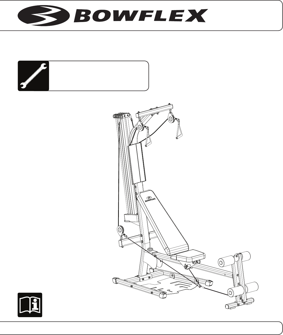
Assembly Manual
Nautilus® Bowflex® Schwinn® Fitness Universal®
PR1000 Home Gym
001-7276.101512.E
®®
Table of Contents
Before Assembly ..................................................................... 2
Tools ........................................................................................... 2
Important Safety Instructions ................................................ 3
Hardware .................................................................................. 4
Parts ........................................................................................... 5
Assembly .................................................................................. 7
Attach the Lower Lat Tower to the Base ...................... 7
Secure the Lower Lat Tower to the Base ..................... 8
Assemble the Seat Rail .................................................... 9
Assemble the Leg Extension ......................................... 10
Attach the Seat Rail to the Leg Extension .................. 11
Attach the Seat Rail to the Base Assembly ............... 12
Upper Lat Tower ..............................................................13
Attach the Upper Lat Tower to the Base Assembly ...............14
Before Assembly
Select where you are going to locate your Bowflex® home gym carefully. The best location is on a hard, level surface. For best
results, assemble your home gym in the location where you intend to use it. For safe operation, allow a workout area of at least
127” x 82” (3.3m x 2.1m) of free space.
Follow these basic tips when assembling your home gym
.
1. Collect all the pieces needed for each assembly step.
2. Turn all the bolts and locknuts toward the right to tighten
. Turn towards the left to loosen.
3. Use a combination wrench to grip the locknut when you tighten a bolt that has a locknut to make sure it is tight.
4.
You may find the use of a utility knife or scissors beneficial during the unpacking and assembly process.
5. Carefully lift pieces when attaching. Look through the bolt holes to help guide bolt placement.
6. Assembly requires 2 people.
NOTICE: Leave all of the cables wrapped and bagged until the Bowflex® home gym is completely assembled.
Tools
• (2)AdjustableWrenches(notincluded)
• Phillips Head Screwdriver (not included)
Apply the Cable Clip ....................................................... 15
Attach the Rod Pack ..................................................... 16
Chest Bar with Pulleys ................................................... 17
Leg Extension Rollers ..................................................... 18
Attach the Bench ........................................................... 19
Attach Placard ............................................................... 20
Level the Machine .......................................................... 21
Connect the Cables to the PowerRod® Unit, Chest
Bar, and Handgrips ......................................................... 22
Connect the Cables from the Chest Bar and Lat
Cross Bar to the Handgrips ........................................... 23
Connect the Cables from the Chest Bar to the
Leg Extension .................................................................. 24
Final Inspection ............................................................... 24
Contacts................................................................................... 28
To validate warranty support, keep the original proof of purchase and record the following information:
Serial Number __________________________
Date of Purchase _______________________
To register your product warranty , go to: www.bowflex.com/register
Or call 1 (800) 605–3369.
If you have questions or problems with your product, please call 1 (800) NAUTILUS (628–8458).
Assembly Manual
2

Important Safety Instructions
• Keepbystandersandchildrenawayfromtheproductyouareassemblingatalltimes.
• Donotassemblethismachineoutdoorsorinawetormoistlocation.
• Makesureassemblyisdoneinanappropriateworkspaceawayfromfoottrafficandexposuretobystanders.
• Somecomponentsofthemachinecanbeheavyorawkward.Useasecondpersonwhendoingtheassembly
stepsinvolvingtheseparts.Donotdostepsthatinvolveheavyliftingorawkwardmovementsonyourown.
• Setupthismachineonasolid,level,horizontalsurface.
• Donottrytochangethedesignorfunctionalityofthismachine.Thiscouldcompromisethesafetyandcanvoid
the warranty.
• If replacement parts are necessary use only genuine Nautilus® replacement parts and hardware. Failure to
use genuine replacement parts can cause a risk to users, keep the machine from operating correctly or void the
warranty.
• Donotusethemachineuntilithasbeenfullyassembledandinspectedforcorrectperformanceinaccordance
with the Owner’s Manual.
• ReadandunderstandthecompleteOwner’sManualsuppliedwiththismachinebeforefirstuse.Keepthe
Owner’s and Assembly Manuals for future reference.
• Doallassemblystepsinthesequencegiven.Incorrectassemblycanleadtoinjury.
Thisiconmeansapotentiallyhazardoussituationwhich,ifnotavoided,couldresultindeathorseriousinjury.
Read and understand all warnings on this machine.
Carefully read and understand the Assembly Manual.
Obey the following warnings:
Assembly Manual
3
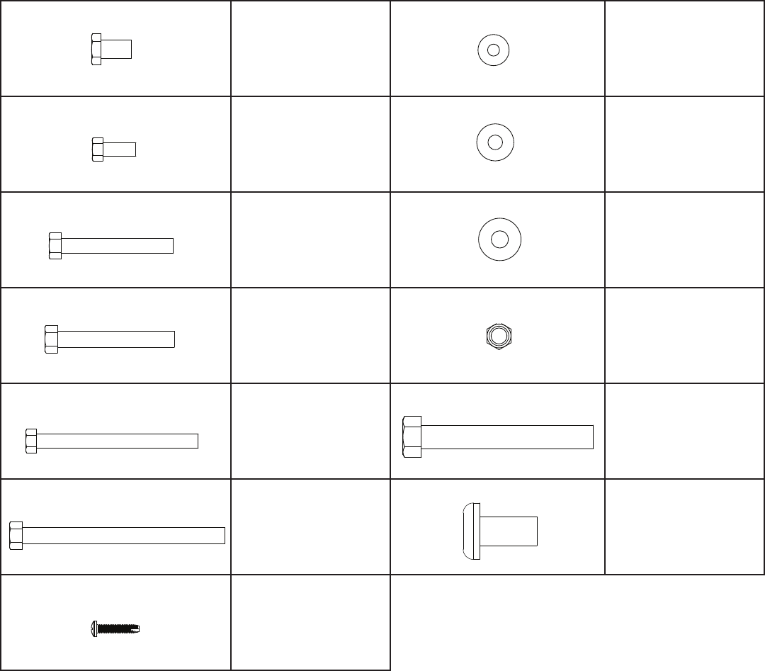
Hardware
(Hardwarenotactualsize)
Qty. 4
Item #1
5/16”x 3/4” Hex Head
Bolt
Qty. 5
Item #8
1/4”Washer
Qty. 8
Item #2
3/8”x 3/4” Hex Head
Bolt
Qty. 4
Item #9
5/16”Washer
Qty. 2
Item #3
3/8”x 2 3/4” Hex Head
Bolt
Qty. 29
Item #10
3/8”Washer
Qty. 4
Item #4
3/8”x 3” Hex Head Bolt
Qty. 10
Item #11
3/8” Nut
Qty. 2
Item #5
3/8”x 4” Hex Head Bolt
Qty. 1 Item #12
3/8” x 4 1/4” Hex
Head Bolt
Qty. 2
Item #6
3/8”x 5” Hex Head Bolt
Qty. 2 Item #13
1/4” x 1” Phillips
Head Bolt
Qty. 3
Item #7
#10 x 1” Self Tapping
Screw
Assembly Manual
4
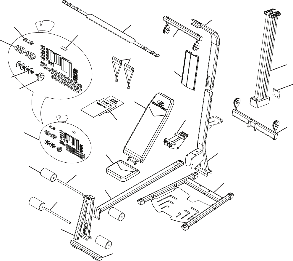
Parts
26
22
19
18
30
37
16
23
20
34
39
27 29
28
24
25
17
21
31
15
14
33
35
38
36
32
Assembly Manual
5

14 1 Hardware Bag
15 1 Pair Handgrips
16 1 Bench
17 1 Base Platform
18 1 Lat Cross Bar
19 1 Upper Lat Tower
20 1 Sliding Seat
21 1 Lower Lat Tower
22 1 Chest Pulley Cross Bar
23 1 Seat Rail with Slider
24 1 Leg Extension
25 1 Leg Extension Base
26 1 Bowflex® Rod Pack
27 4 Foam Roller Pads
28 1 Short Roller Tube
29 1 Long Roller Tube
30 1 Exercise Placard
31 1 Rod Box End Plate
32 1 ManualKit
33 4 End Caps
34 4 Clips
35 1 ThreadedKnob
36 1 Seat Slider
37 1 Leg Press Belt
38 1 Rubber Pad
39 1 Cable Clip
Item # Item #
Qty. Qty.
Description Description
Parts
Assembly Manual
6
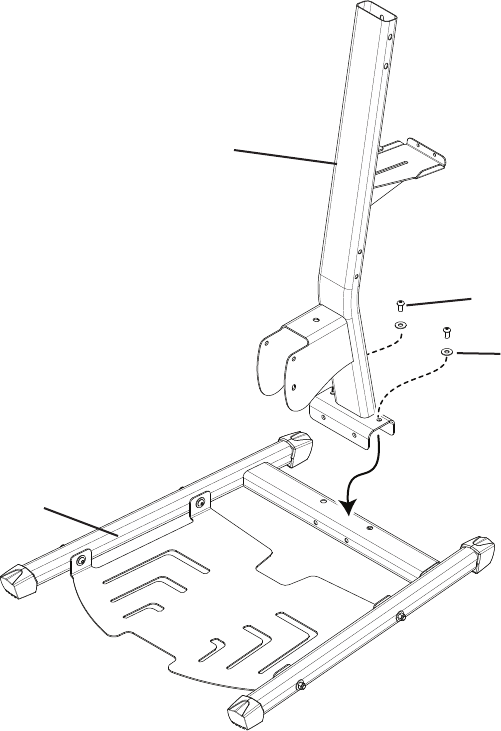
Assembly
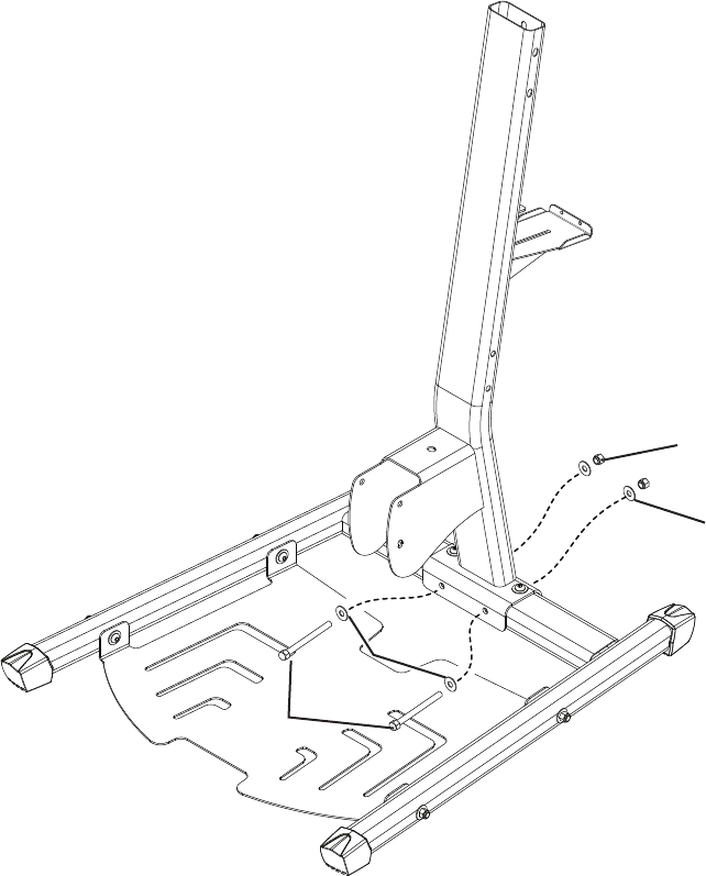
Step 1: Attach the Lower Lat Tower to the Base
Parts
• BasePlatform(#17)
• LowerLatTower(#21)
Hardware
• (2)3/8”x3/4”HexHeadBolts(#2)
• (2)3/8”Washers(#10)
Tools
• AdjustableWrench(notincluded)
1-1 Attach the Lower Lat Tower to the Base Platform with first set of bolts.
Note:Donottightenhardware.
17
21
2
10
Assembly Manual
7
Assembly
Step 2: Secure the Upper Lat Tower to the Base
Parts
• CompletedAssembly(fromstep1)
Hardware
• (2)3/8”x4”HexHeadBolts(#5)
• (4)3/8”Washers(#10)
• (2)3/8”Nuts(#11)
Tools
• (2) AdjustableWrenches(notincluded)
2-1 Install the second set of bolts and tighten all of the hardware.
11
10
5
10
Assembly Manual
8
Assembly
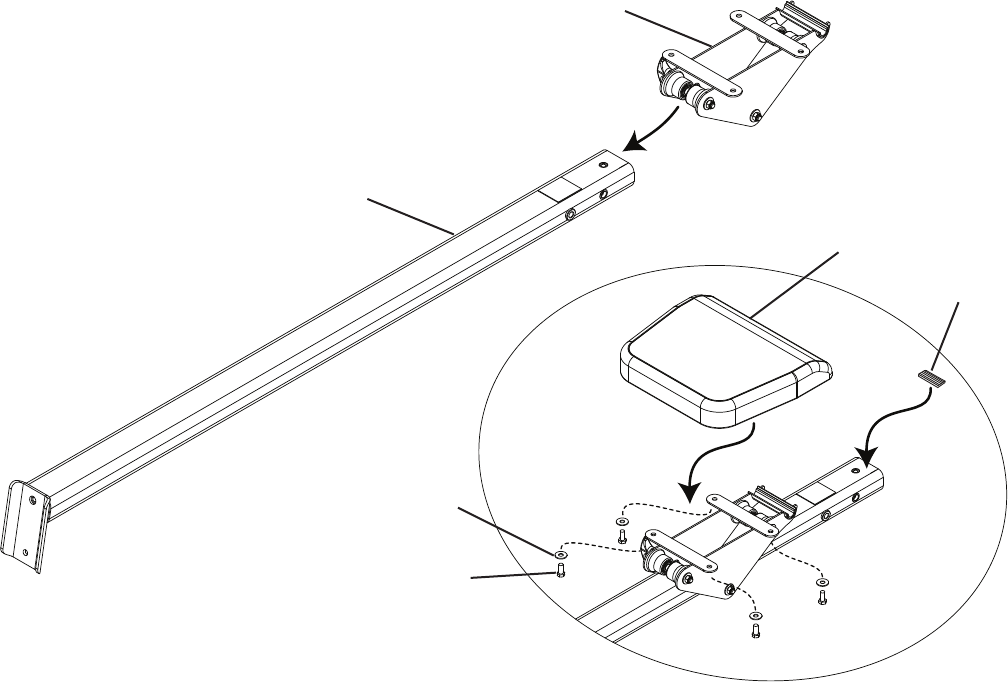
Step 3: Assemble the Seat Rail
Parts
• SeatRail(#23)
• SeatCushion(#20)
• SeatSlider(#36)
Hardware
• (4)5/16”x3/4”HexHeadBolts(#1)
• (4)5/16”Washers(#9)
• (1)RubberPad(#38)
Tools
• AdjustableWrench(notincluded)
3-1 Slide the Seat Slider onto the Seat Rail.
Note: The threaded hole on the end of the Seat Rail must face upward.
3-2AttachtheSeatCushiontotheSeatSliderwiththeHexHeadBoltsandWashers.Tightenhardware.
3-3 Apply the Rubber Pad to the upper end of the Seat Rail.
20
23
1
9
38
36
Assembly Manual
9
Assembly
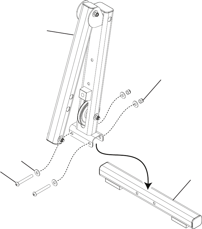
Step 4: Assemble the Leg Extension
Parts
• LegExtension(#24)
• LegExtensionCrossTube(#25)
Hardware
• (2)3/8”x3”HexHeadBolt(#4)
• (4)3/8”Washers(#10)
• (2)3/8”Nut(#11)
Tools
• (2)AdjustableWrenches(notincluded)
4-1 Set the bracket end of the Leg Extension onto the Leg Extension Tube and align the bolt holes.
4-2 Install and tighten the hardware.
Note:Donotunwrapthecablefromthepulley.
4
10
24
25
11
Assembly Manual
10
Assembly
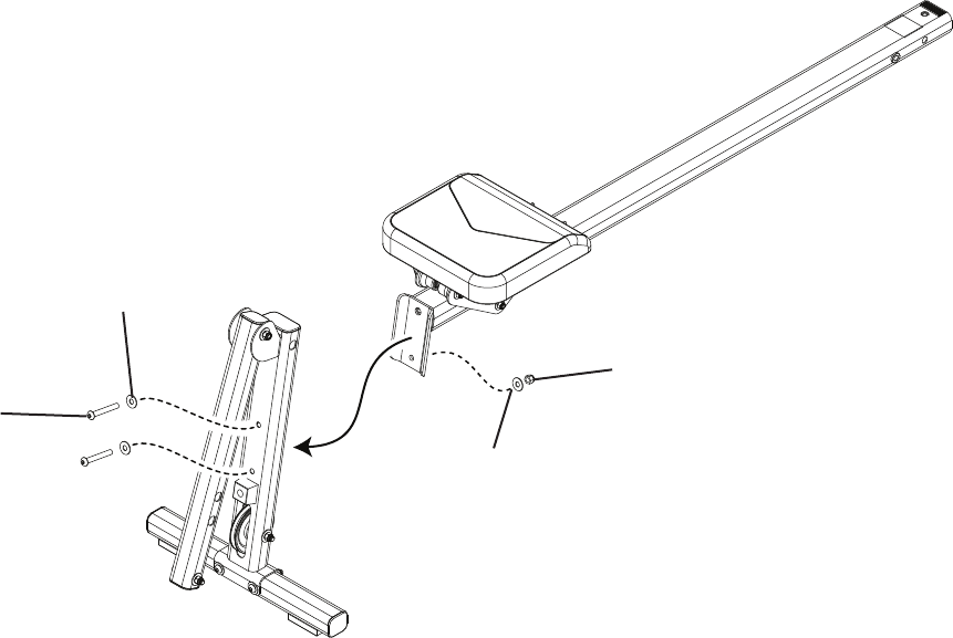
Step 5: Attach the Seat Rail to the Leg Extension
Parts
• SeatRailAssembly(fromstep3)
• LegExtensionAssembly(fromstep4)
Hardware
• (2)3/8”x23/4”HexHeadBolt(#3)
• (3)3/8”Washers(#10)
• (1)3/8”Nut(#11)
Tools
• (2)AdjustableWrenches(notincluded)
5-1 Align the bolt holes of the Seat Rail Assembly with the bolt holes in the Leg Extension Assembly.
5-2 Install and tighten the hardware.
Note:Donotunwrapthecablesfromthepulleys.
3
10
11
10
Assembly Manual
11
Assembly
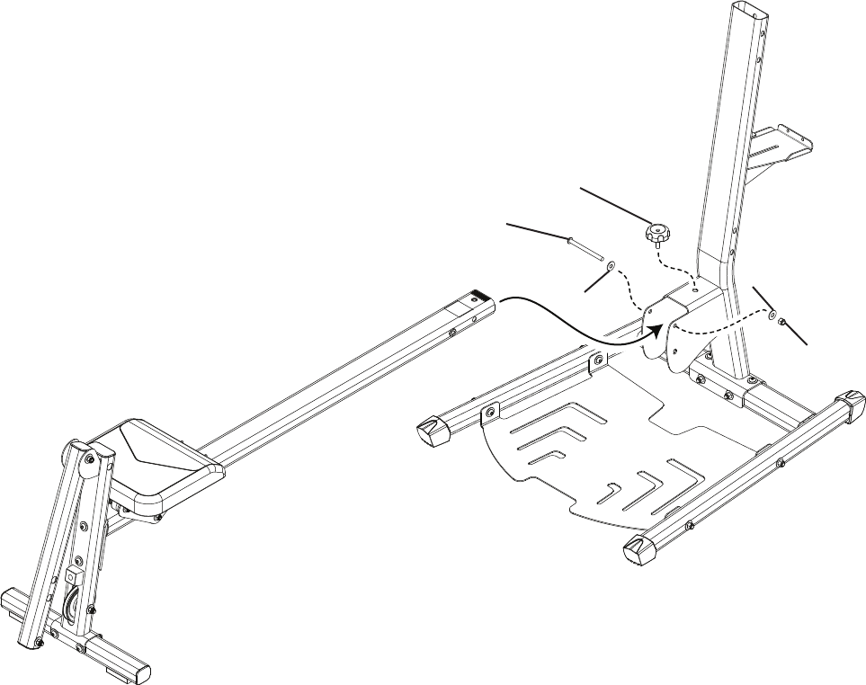
Step 6: Attach the Seat Rail to the Base Assembly
Parts
• SeatRailAssembly(fromstep5)
• CompletedAssembly(fromstep2)
Hardware
• (1)3/8”x41/4”HexHeadBolt(#12)
• (2)3/8”Washers(#10)
• (1)3/8”Nut(#11)
• (1)ThreadedKnob(#35)
Tools
• (2)AdjustableWrenches(notincluded)
6-1 Insert the Seat Rail Assembly into the Lower Lat Tower Assembly.
6-2 Install and tighten the hardware.
35
10
10
11
12
Assembly Manual
12
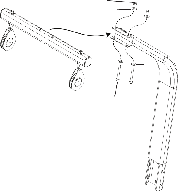
Assembly
Step 7: Upper Lat Tower
Parts
• UpperLatTower
• LatTowerCrossBarwithPulleysandCables
Hardware
• (2)3/8”x3”HexHeadBolt(#4)
• (4)3/8”Washers(#10)
• (2)3/8”Nut(#11)
Tools
• (2)AdjustableWrenches(notincluded)
7-1 Align the Lat Tower Cross Bar bolt holes with the bolt holes in the Upper Lat Tower bracket.
7-2 Install and tighten the hardware.
Note: Donotunwrapthecablesfromthepulleys.
11
10
4
10
Assembly Manual
13
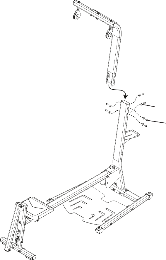
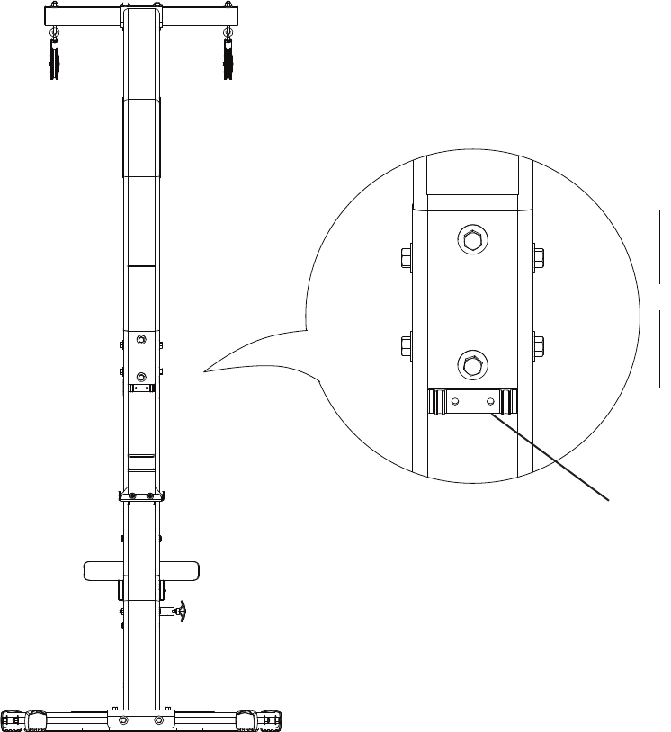
Assembly
Step 8: Attach the Upper Lat Tower to the Base Assembly
Parts
• UpperLatTowerAssembly(fromstep7)
• CompletedAssembly(fromstep6)
Hardware
• (6)3/8”x3/4”HexHeadBolt(#2)
• (6)3/8”Washers(#10)
Tools
• (2)AdjustableWrenches(notincluded)
8-1 Insert the Upper Lat Tower Assembly into the Lower Lat Tower.
8-2 Install and tighten the hardware.
2
10
Assembly Manual
14
Assembly
Step 9: Apply the Cable Clip
Parts
• (1)CableClip(#39)
• CompletedAssembly(fromstep8)
9-1 Apply the Cable Clip to the rear of the Lower Lat Tower.
Note: Be sure to use the cable clip when the cables are not in use.
6” (15.25cm)
39
Assembly Manual
15
Assembly
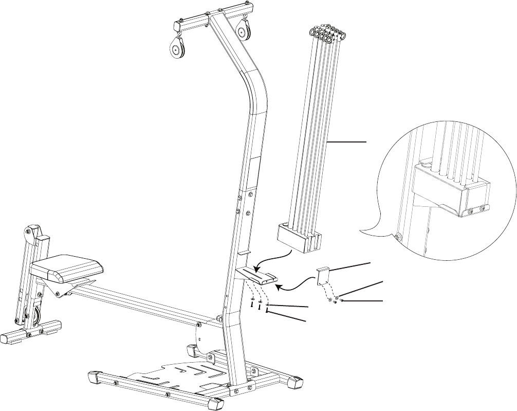
Step 10: Attach the Rod Pack
Parts
• CompletedAssembly(fromstep9)
• (1)Bowex®RodPack(#26)
• (1)RodBoxEndPlate(#31)
Hardware
• (3)#10x1”SelfTappingScrews(#7)
• (2)1/4”x1”PhillipsHeadBolt(#13)
• (5)1/4”Washers(#8)
Tools
• PhillipsHeadScrewDriver(notincluded)
10-1 Slide the Bowflex® Rod Pack into the Rod Pack Holder.
10-2 Install and completely tighten the hardware.
Note: Make sure that the hardware is tightly secured.
26
7
813
8
31
Assembly Manual
16
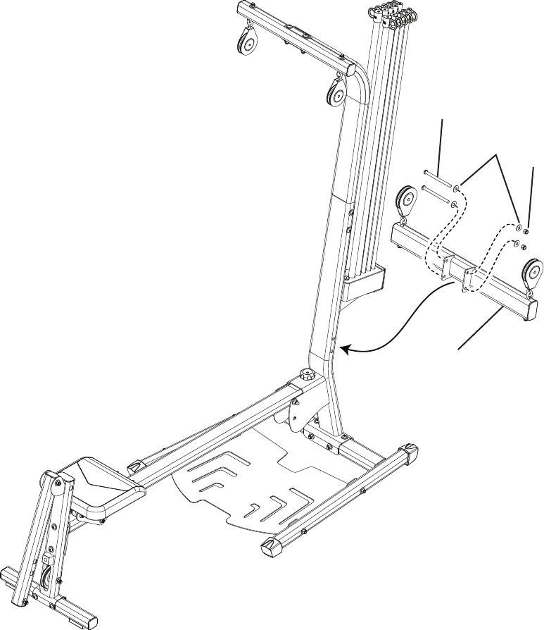
Step 11: Chest Bar with Pulleys
Parts
• CompletedAssembly(fromstep10)
• ChestBarwithPulleysandCables(#22)
Hardware
• (2)3/8”x5”HexHeadBolts(#6)
• (4)3/8”Washers(#10)
• (2)3/8”Nuts(#11)
Tools
• (2) AdjustableWrenches(notincluded)
11-1 Attach the Chest Bar with Pulleys and Cables to the Lower Lat Tower.
6
10 11
22
Assembly
Assembly Manual
17
Assembly
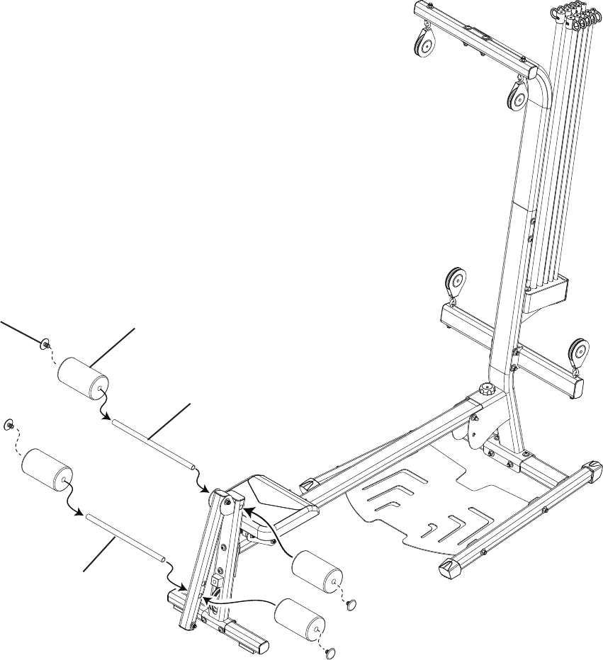
Step 12: Leg Extension Rollers
Parts
• (4)FoamRollerPads(#27)
• (4)TubeEndPlugs(#33)
• (1)LongRollerTube(#29)
• (1)ShortRollerTube(#28)
• CompletedAssembly(fromstep11)
12-1 Insert the Roller Tubes through the Leg Extension.
12-2 Slide the Foam Rollers onto the Roller Tubes.
12-3 Plug the Roller Tube ends with the Tube End Plugs.
27
33
29
28
Assembly Manual
18
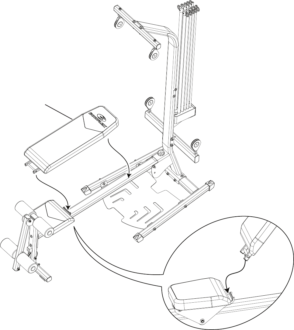
Assembly
Step 13: Attach the Bench
Parts
• BenchCushion(#16)
• CompletedAssembly(fromstep12)
13-1 Put the Bench Cushion onto the Seat Rail and the Seat Slider.
16
Assembly Manual
19
Assembly
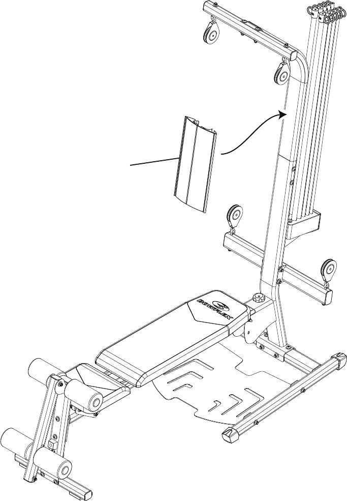
Step 14: Attach Placard
Parts
• ExercisePlacard(#30)
• CompletedAssembly(fromstep13)
14-1 Snap the Excercise Placard onto the upper Lat Tower.
30
Assembly Manual
20
Assembly
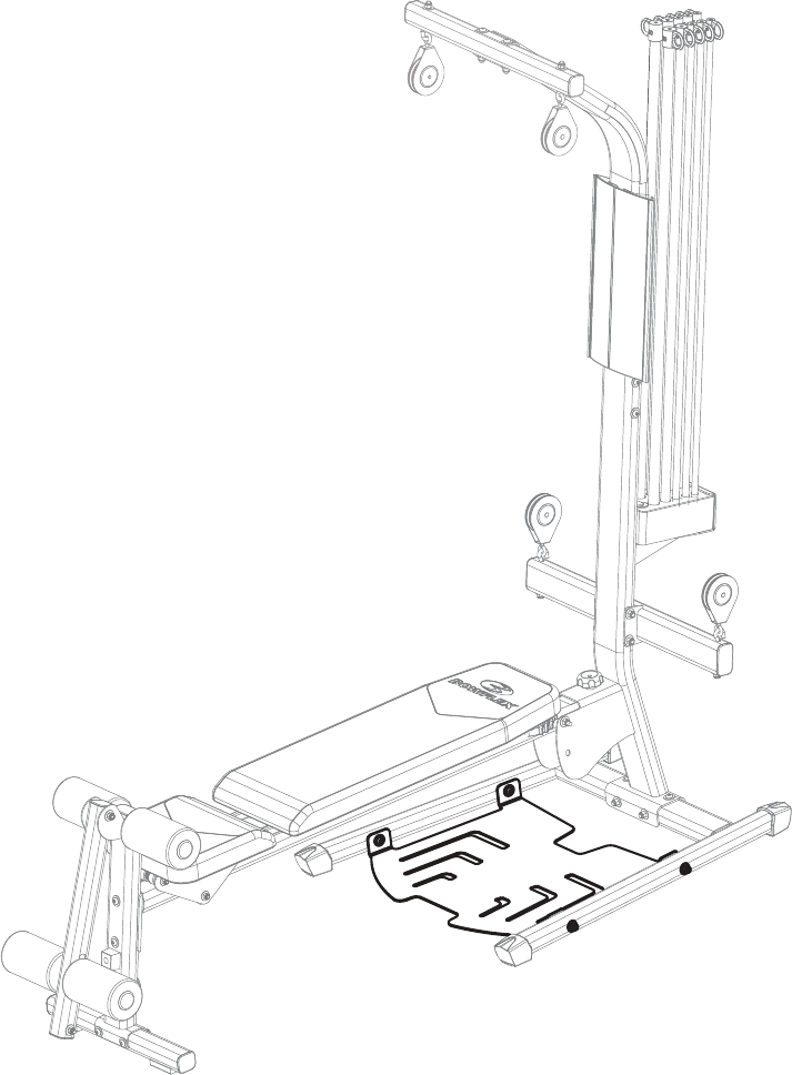
Step 15: Level the Machine
Parts
• CompletedAssembly(fromstep14)
Tools
• (2) AdjustableWrenches(notincluded)
15-1 Loosen but do not remove the bolts on the foot plate.
15-2 Stand on the foot plate until it rests flat on the floor.
15-3 Re-tighten the bolts.
Assembly Manual
21
Assembly
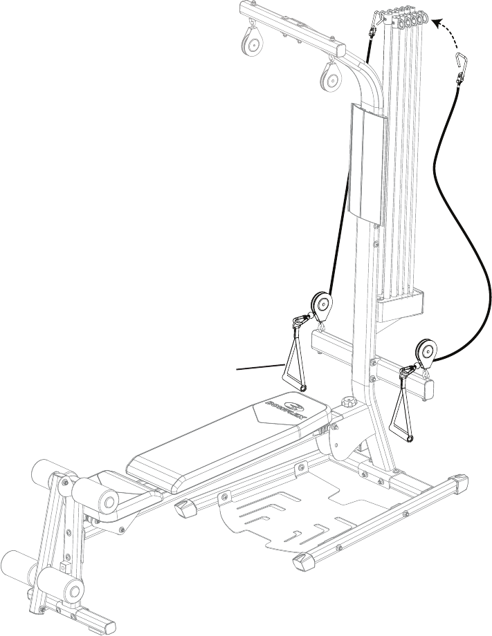
Step A: Connect the Cables to the Power Rod® Unit, Chest Bar, and Handgrips
Parts
• (2)Handgrips(#15)
A-1 Remove the plastic and unwrap the cables from the Chest Bar Pulleys.
A-2 Attach the Rod Hooks to the Power Rod® Unit.
A-3 Connect the Handgrips to the Snap Hooks on the Cables.
15
Assembly Manual
22
Assembly
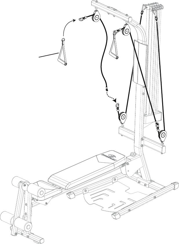
Step B: Connect the Cables from the Chest Bar and Lat Cross Bar to the Handgrips
Parts
• (2)Handgrips(#15)
B-1 Remove the plastic and unwrap the cables from the Lat Bar Pulleys.
B-2 Attach the Snap Hooks from the Chest Bar Pulleys to the Cables on the Lat Cross Bar.
B-3 Attach the Handgrips to the Snap Hooks from the Lat Cross Bar.
15
Assembly Manual
23
Assembly
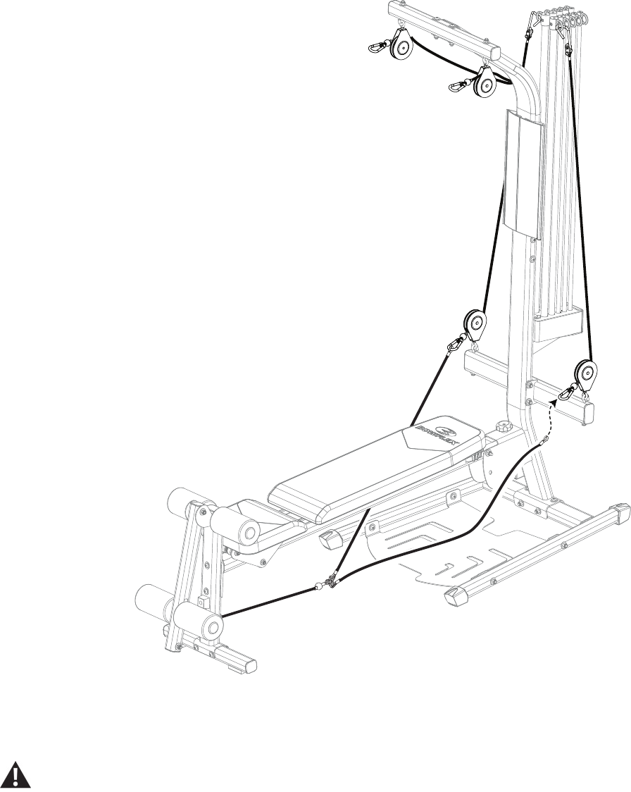
Step C: Connect the Cables from the Chest Bar to the Leg Extension
C-1 Remove the plastic and unwrap the cables from the Leg Extension Pulleys.
C-2 Attach the Snap Hooks from the Chest Bar Pulleys to the Leg Extension Cables.
Final Inspection
Inspect your machine to ensure that all fasteners are tight and components are properly assembled.
Donotuseuntilthemachinehasbeenfullyassembledandinspectedforcorrectperformanceinaccordancewith
the Owner’s Manual.
Assembly Manual
24
Assembly Manual
25
Assembly Manual
26
Assembly Manual
27

Nautilus, Inc., (800) NAUTILUS / (800) 628-8458, www.NautilusInc.com - Customer Service: North America (800) 605-3369, csnls@nautilus.com | outside U.S. +01-360-859-
5180, technics-APLA@nautilus.com | Printed in China | © 2008 Nautilus, Inc..
Nautilus® Bowflex® Schwinn® Fitness Universal®
EN
