Bowflex Ultimate 2 Owner S Manual
Assembly Manual BFX_Ultimate2_AM_RevC_web Bowflex Product Manuals | Bowflex
Bowflex Ultimate 2 Home Gym Assembly Manual assembly_ultimate2 Troubleshoot Bowflex Ultimate 2 Home Gym Assembly |
Assembly Manual BFX_Ultimate2_AM_RevC_web Bowflex Product Manuals | Bowflex
2014-07-05
: Bowflex Bowflex-Bowflex-Ultimate-2-Owner-S-Manual bowflex-bowflex-ultimate-2-owner-s-manual bowflex pdf
Open the PDF directly: View PDF ![]() .
.
Page Count: 48
WWWBOWFLEXCOM
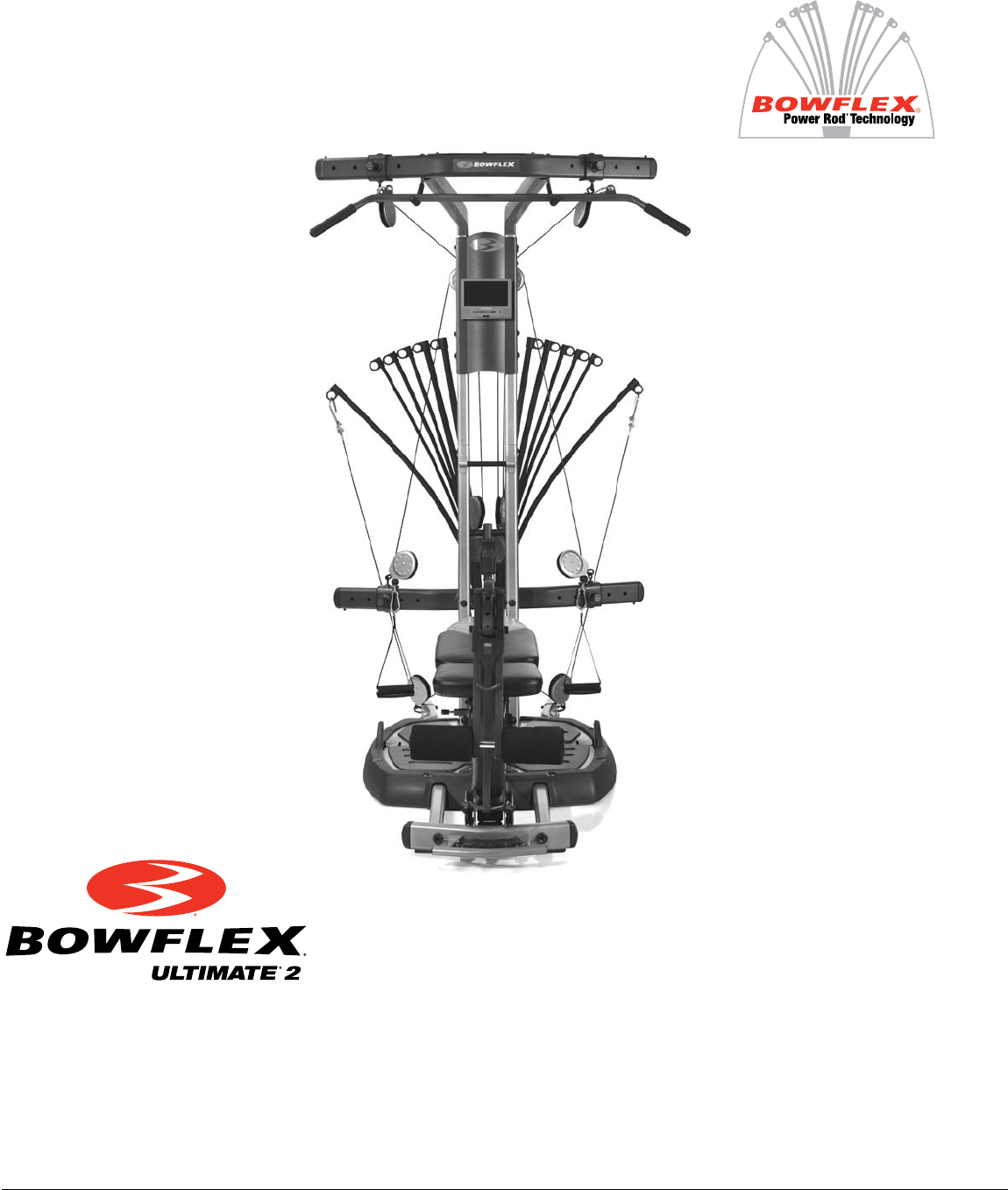
The Bowflex Ultimate® 2
Assembly Instructions
000-4300-092308C
(Shown with optional accessories)

1
Congratulations
Congratulations on your commitment to improving your health and fitness! With the Bowflex Ultimate
®
2 home
gym, you have everything you need to exceed all of your physical fitness, strength and health expectations!
The Bowflex Ultimate® 2 home gym’s exceptional resistance and quality is unmatched by any other single piece
of home fitness equipment available. You will not believe the amazing results your body will get with the Bowflex
Ultimate® 2 home gym!
With all of the fitness choices available today, finding the best workout equipment for your needs can be confusing.
Everyone at Nautilus would like to congratulate you and thank you for selecting the Bowflex Ultimate® 2 home
gym.
The Bowflex Ultimate® 2 home gym is the best home fitness product available, and you’re just about to prove it to
yourself.
Assembly Guide Table of Contents
Bowflex Ultimate® 2 Seat Rail Securing Device .2
Before You Start .....................................................5
Bowflex Ultimate® 2 Parts Reference Guide ......6
Parts List ..................................................................7
Tools You Will Need .............................................15
Hardware Chart ....................................................16
Assembling Your Bowflex Ultimate® 2 Gym .....17
Installing Your Bowflex Ultimate® 2 Cables ......35
Installing Your Bowflex Ultimate® 2 Accessories
Squat Attachment............................................41
Leg Extension ..................................................43
Leg Extension Seat .........................................44
Preacher Curl ..................................................44
Bench ...............................................................45
Ab Crunch Attachment ..................................45
DVD Player ......................................................46
2
Bowflex Ultimate® 2 Seat Rail Securing Device Addendum
NOTICE: This Addendum provides important instructions for securing the Bowflex Ultimate® 2 Home
Gym Seat Rail to the Seat Rail Securing Device. Be aware that the Owner’s and Assembly
Manuals refer to the Seat Rail Securing Device as the "Squat Holder" and/or "rail securing
device".
If you need assistance, please call Bowflex® Customer Service at 1-800-628-8458.
WARNING Failure to secure the Seat Rail Securing Device into
the Seat Rail may cause injury.
It is important to latch the Seat Rail Securing Device into the Seat Rail
before performing the following exercises:
• StandingLatRow
• StandingBicepsCurl(withpulleys)
• Squat
• Lunge
• StandingCalfPress
• WideSquat
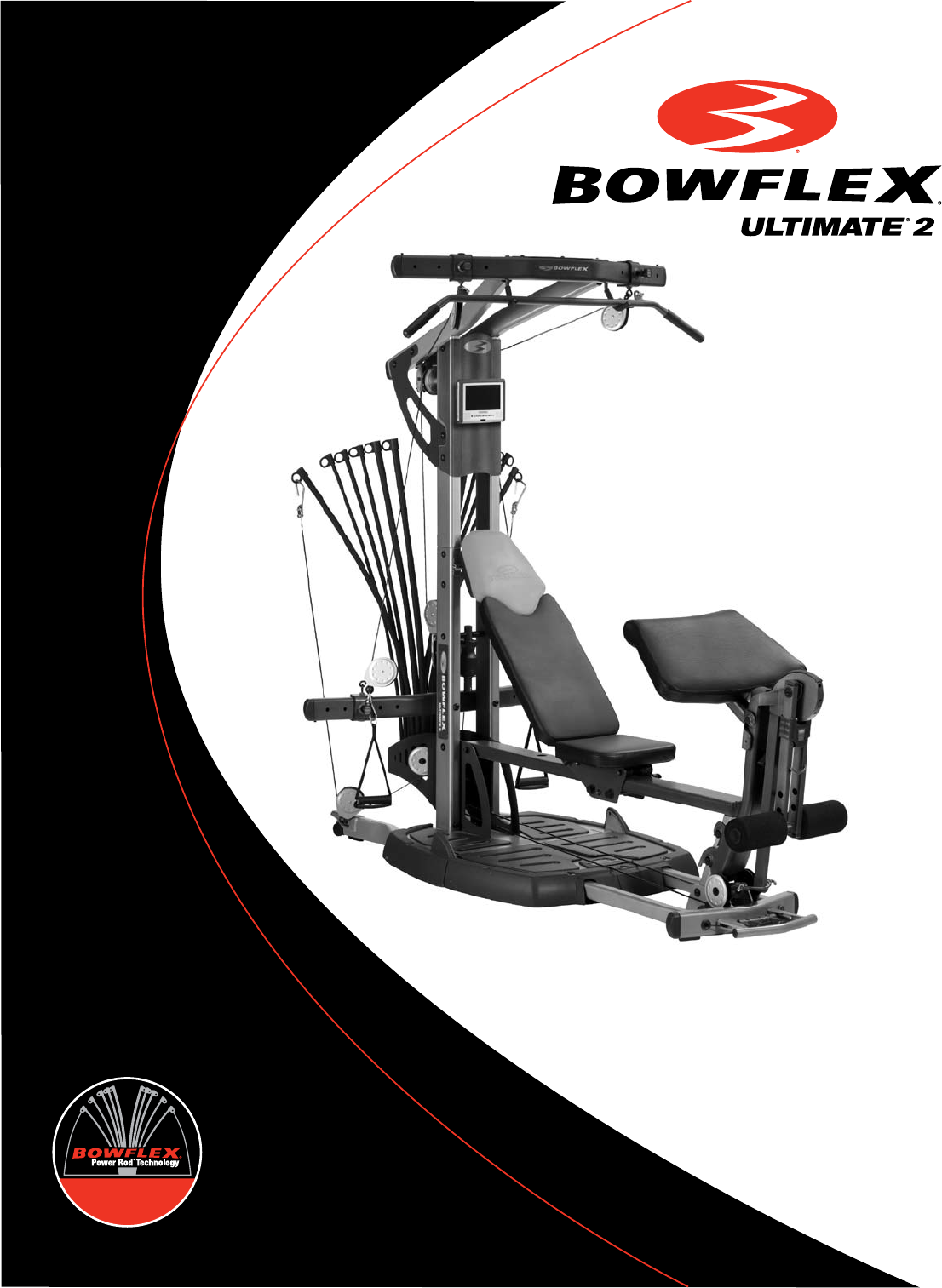
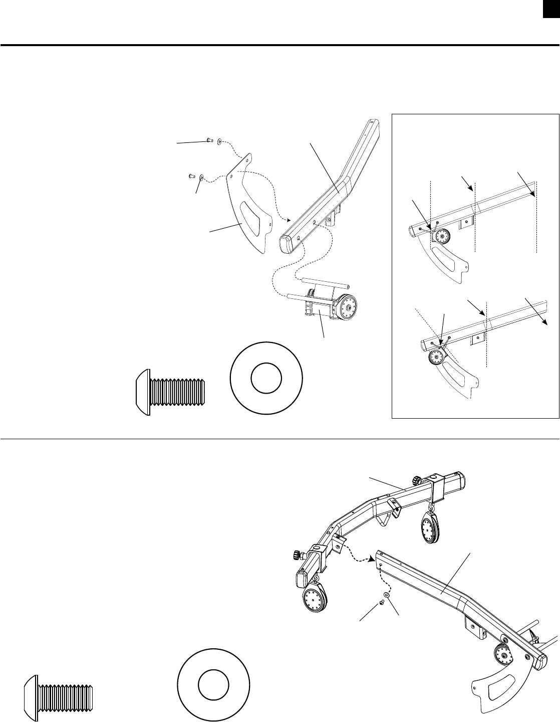
Part A
Latch the Seat Rail Securing Device
Step 1: Remove the Seat Back
Step 2: Lock the Sliding Seat
2-1 SeatmustbelockedattheendoftheSeatRail.
2-2 Makesurethattheslidingseatlockhandleisinthelockedposition
(Figure1).
Step 3: Lift the Seat Rail
3-1 BendatthekneesandgrabtheSeatRailwithonehandandthe
lockedSlidingSeatwithyourotherhand(Figure2).
3-2 UseyourlegstolifttheSeatRail(Figure3).
(Part A continued on page 2)
Figure 1
Figure 2
Figure 3
3
Figure 4
Figure 5
Figure 6
Bowflex Ultimate® 2 Seat Rail Securing Device Addendum
Figure 7
Part A (continued)
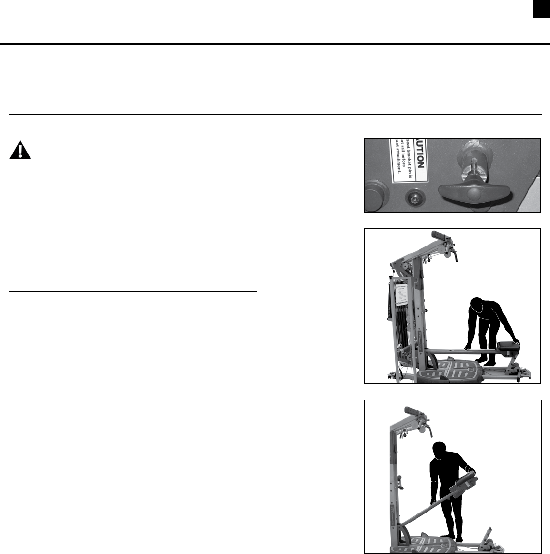
Step 4: Latch the Seat Rail Securing Device
4-1 Insert the Seat Rail Securing Device into the hole in the Seat Rail
untilitclicks(Figures4,5,6).
Step 5: Make sure that the Seat Rail is secured.
5-1 StandtothesideofthemachinebaseandSeatRail.
WARNINGDonotstandonthebasebelowtheSeatRailwhenyou
pull on it. This may cause injury.
5-2 PulldownontheSeatRailtomakesurethattheSeatRailSecuring
Deviceissecured(Figure7).
Seat Rail
Securing
Device
Seat Rail
4
Bowflex Ultimate® 2 Seat Rail Securing Device Addendum
Figure 8
Figure 9
Figure 10
Figure 11
Figure 12
Part B
Release the Seat Rail Securing Device
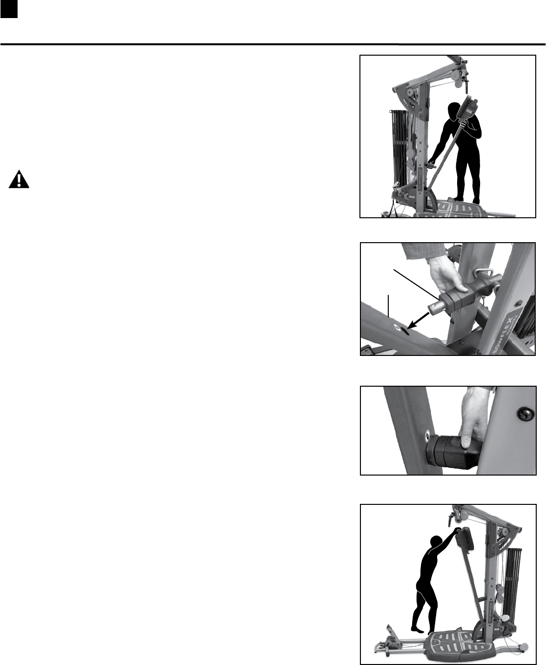
Step 1: Secure the Seat Rail Securing Device
1-1 Withyourinsidefootonthemachinebase,holdtheSeatRailwith
onehandandpushyourshoulderintoitlightly(Figure8).
1-2 ContinuetoholdtheSeatRailwithonehandandyourshoulder.Use
yourfreehandtounlocktheSeatRailSecuringDevice(Figures8
and9)untilitreleases(Figure10).
Step 2: Lower the Seat Rail
2-1 WhentheSeatRailSecuringDevicereleases,usebothhandsto
holdontotheSeatRail(Figure11).
2-2 Usebothhandstocarefullylowertheseatdownintothehorizontal
position(Figure12).
WARNINGDonotstandonthebasebelowtheSeatRailwhenyou
lower it. This may cause injury.
WARNINGAlwaysusebothhandstoliftandlowertheSeatRail.
BendatthekneeswhenliftingorsettingdowntheSeatRail.
Failuretouseproperliftingtechniquesmaycauseinjury.

5Before You Start
Before You Assemble
Select where you are going to locate your Bowflex
Ultimate® 2 home gym carefully. The best place for
your home gym is on a hard, level surface. For best
results, assemble your home gym in the location where
you intend to use it. Allow a workout area of at least
8’4”L x 6’6”W (2.6m L x 2m W) of free space for safe
operation of the Bowflex Ultimate® 2 home gym.
A minimum of 7’4” of ceiling height will be required to
assemble your Bowflex Ultimate® 2 home gym.
Basic Assembly Principles
Here are a few basic tips that will make your assembly
of the Bowflex Ultimate® 2 home gym quick and easy.
By using these principles, you can simplify each process
and save yourself extra time and effort.
1. To make the assembly process go faster,
gather the pieces you need for each step and
thoroughly read the assembly instructions for
that step prior to starting assembly for the step.
2. When tightening a locknut on a bolt, use a
combination wrench to grip the locknut and
ensure that it is fastened securely.
3. When attaching two pieces, gently lift and look
through the bolt holes to help guide the bolt
through the holes.
4. As a general rule, and for all bolts and nuts on
your Bowflex Ultimate® 2 home gym, turn bolts
or nuts toward the right to tighten and left to
loosen.
NOTE: LEAVE ALL CABLES WRAPPED AND BAGGED UNTIL YOUR
BOWFLEX ULTIMATE® 2 IS FULLY ASSEMBLED.
6
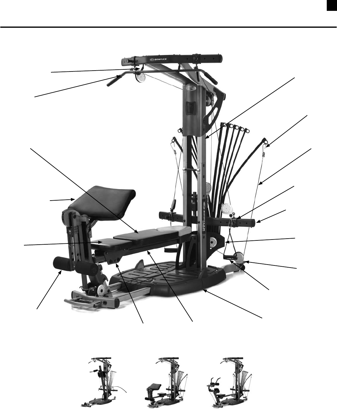
Bowflex Ultimate® 2 Parts Reference Guide
Lat Bar
Lat Bar Rests
Pulley Frame
Rod Hook
Bench
Vertical Main Frame
Seat
Seat Rail
Cable
Rod Box
Adjustable
Pulley System
Pulley
Hand Grip/
Ankle Cuff
Standing/Squat Platform
Spring Lock
Seat Pin
Leg Extension/
Leg Curl Attachment
Squat
Attachment Preacher Curl
Attachment
Ab Curl
Attachment
(optional)
Preacher Curl
Attachment
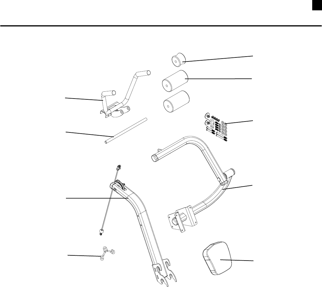
7Box Contents / Parts List
BOX 1
Box 1 Contents
Reference # Qty. Description
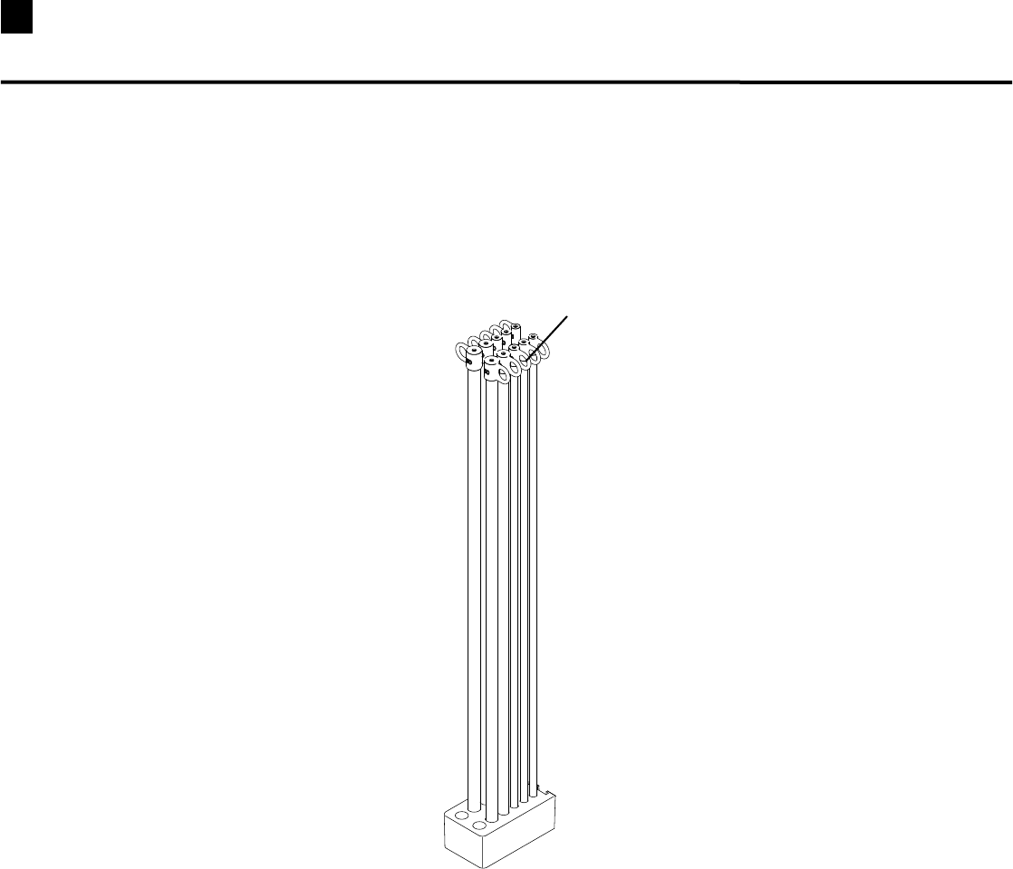
1 1 210lb.RodPack
1
8
Box Contents / Parts List
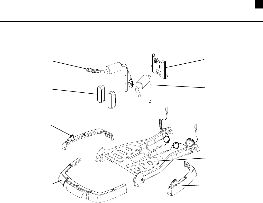
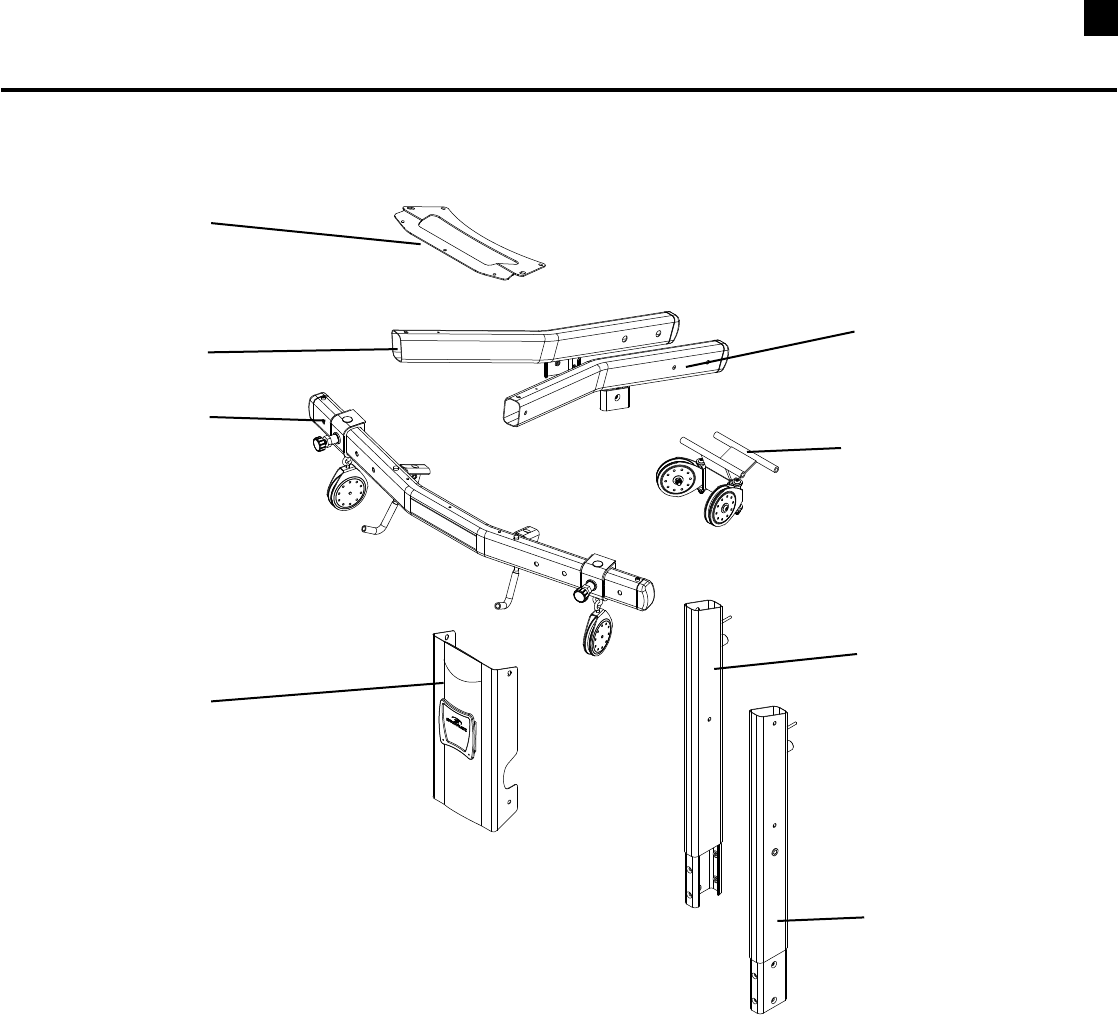
Box 2 Contents
Reference # Qty. Description
2 1 RearBaseAssembly
3 1 RightSquatAssemblyHandlebar
4 1 LeftSquatAssemblyHandlebar
5 1 SquatFrame
6 2 SquatAssemblyPad
7 1 FrontPlasticCover
8 1 RightRearPlasticCover
9 1 LeftRearPlasticCover
BOX 2
2
3
4
5
6
7
8
9
9Box Contents / Parts List
BOX 3
Box 3 Contents
Reference # Qty. Description
10 1 FrontBaseAssembly
11 1 FrontBasePlate
12 1 FrontHandleAssembly
13 2 SinglePulleyAssemblyWithTwoCheeks
14 2 LegExtensionPulleyBracket
10
14
13
11
12
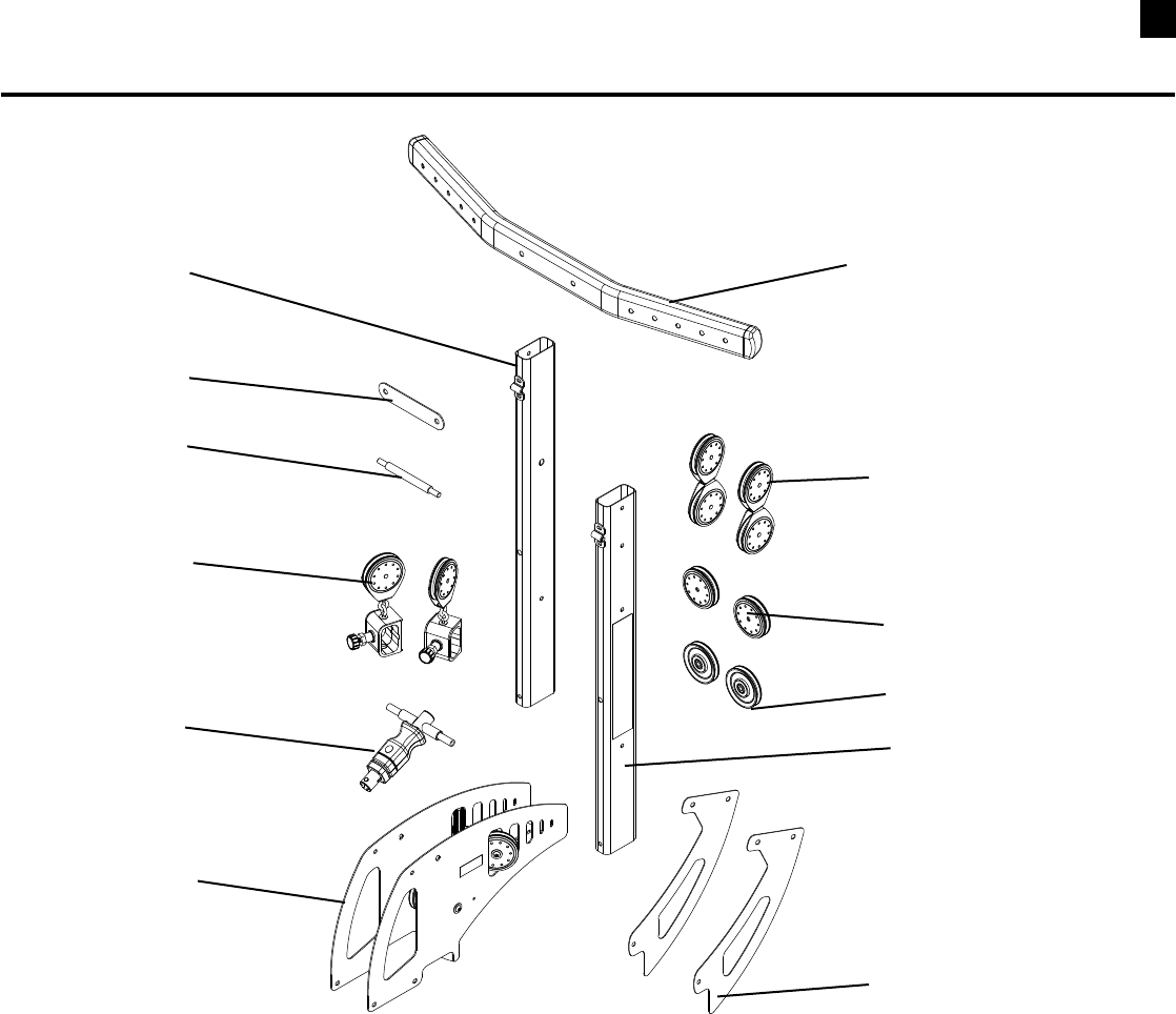
10
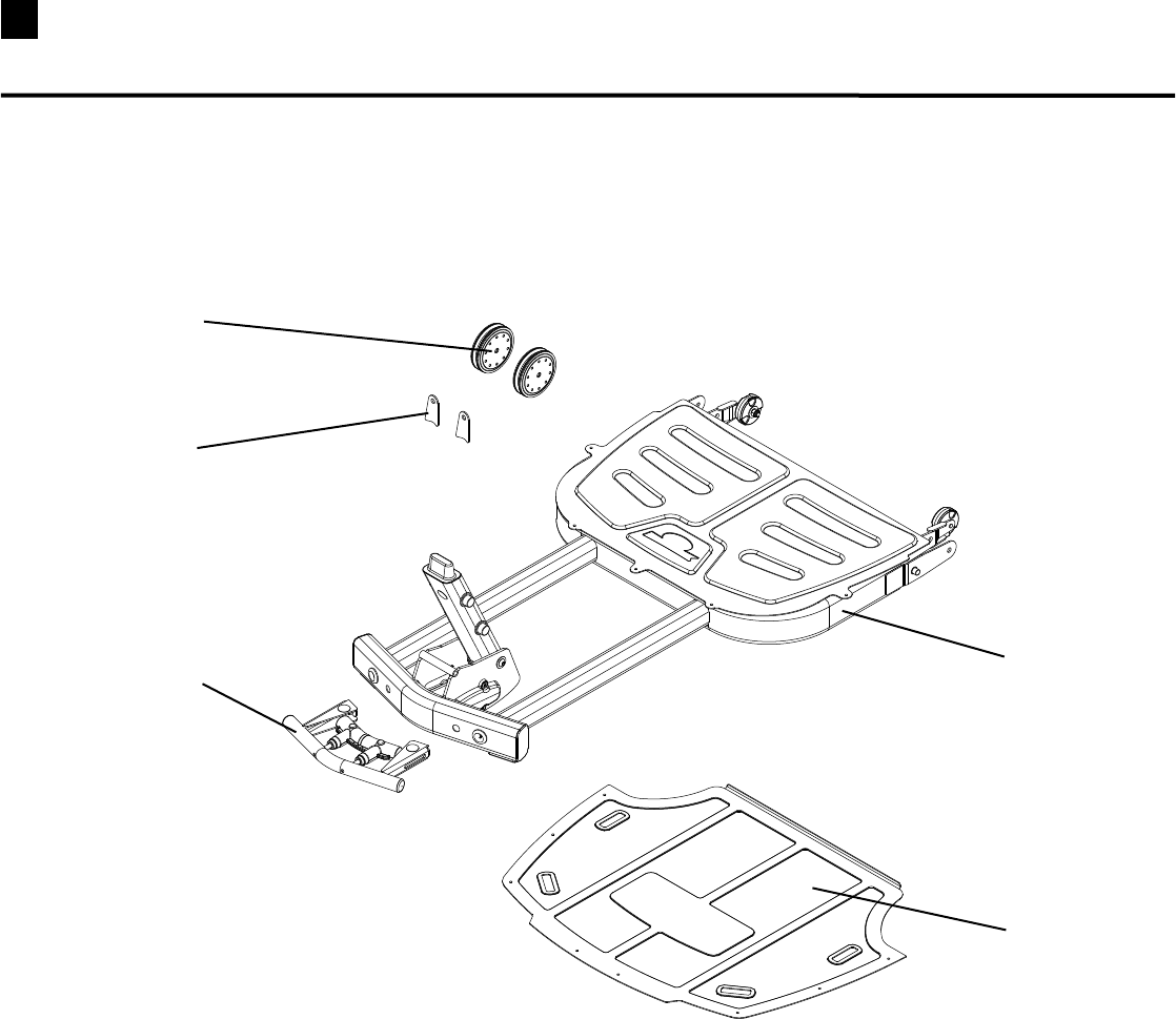
Box Contents / Parts List
BOX 4
Box 4 Contents
Reference # Qty. Description
15 2 SidePlate
16 2 FloatingPulleyassembly
17 2 SinglePulleyAssemblyWithTwoCheeks
18 2 Pulley
19 2 PulleySlider
20 1 CrossBrace
21 1 WasherPlate
22 1 SquatHolder
23 1 RightLowerUpright
24 1 LeftLowerUpright
25 1 RodBox(RodBoxRetainerislocatedonhardwarecard)
26 1 ChestBar
16
23
17
26
21
19
20
24
22
25
18
15
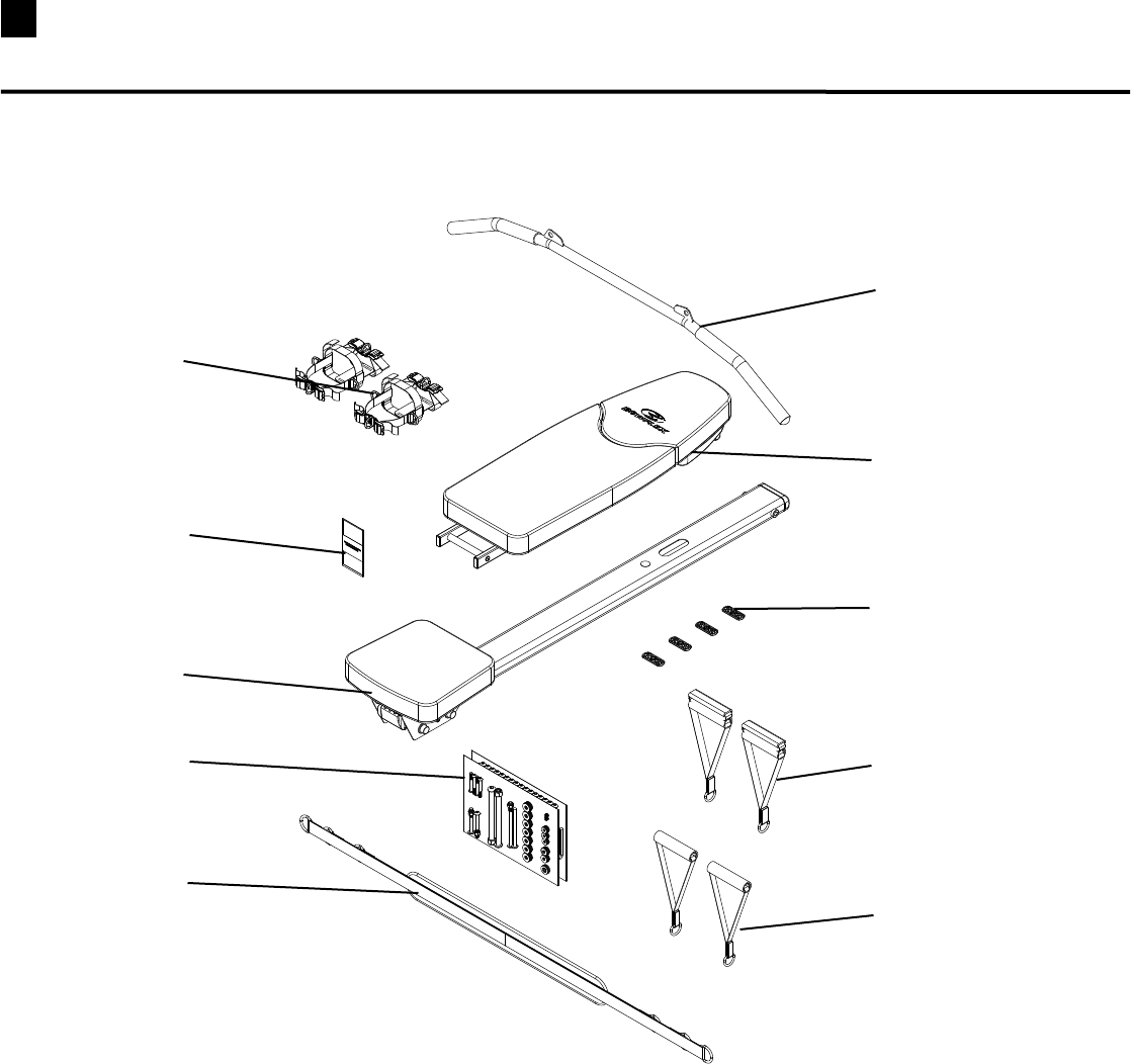
11 Box Contents / Parts List
BOX 5
Box 5 Contents
Reference # Qty. Description
27 1 LatPullDownBar
28 1 Bench
29 4 PlasticFoot
30 2 GripAnkleCuff
31 2 HandGrip
32 2 FootHarness
33 1 FootHarnessInstructions
34 1 SeatRailWithSlidingSeat
35 2 HardwareCards
36 1 RowingBelt
28
29
27
36
33
32
30
34
35
31
12
Box Contents / Parts List
BOX 6
Box 6 Contents
Reference # Qty. Description
37 1 TopPlate
38 1 RightLatBoom
39 1 LeftLatBoom
40 1 LatBarWithPulleySliders
41 1 RearPulleyFrame
42 1 FacePlate
43 1 LeftUpperLatUpright
44 1 RightUpperLatUpright
41
37
39
38
40
42
43
44
13 Box Contents / Parts List
BOX 7
Box 7 Contents
Reference # Qty. Description
45 1 LegExtensionSeatFrame
46 1 LegExtensionSeatPad
47 1 PreacherCurlPad
48 1 HardwareBag
49 1 PreacherCurlBar
50 1 PreacherCurlFrame
51 2 RollerPad
52 1 LegExtensionAssembly
53 1 WebbingWithSteelRings
54 1 LegExtensionRollerShaft
48
49
46
47
45
51
50
52
54
53
14
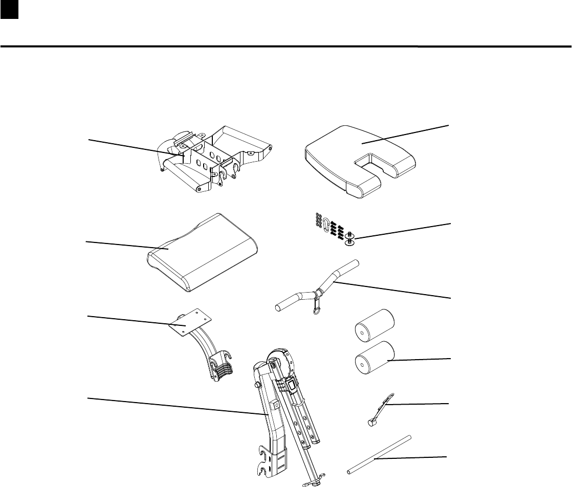
Box Contents / Parts List
Ab Box
Ab Box Contents
Reference # Qty. Description
55 1 AbCrunchMiddlepad
56 1 AbCrunchHandleBar
57 1 HardwareBag
58 1 AbCrunchRollerShaft
59 1 AbCrunchPivotArm
60 1 AbCrunchFrame
61 1 AbCableHook
62 1 AbCrunchBackPad
63 2 AbCruchRollerPads
63
58
55
56
61
60
59
62
57
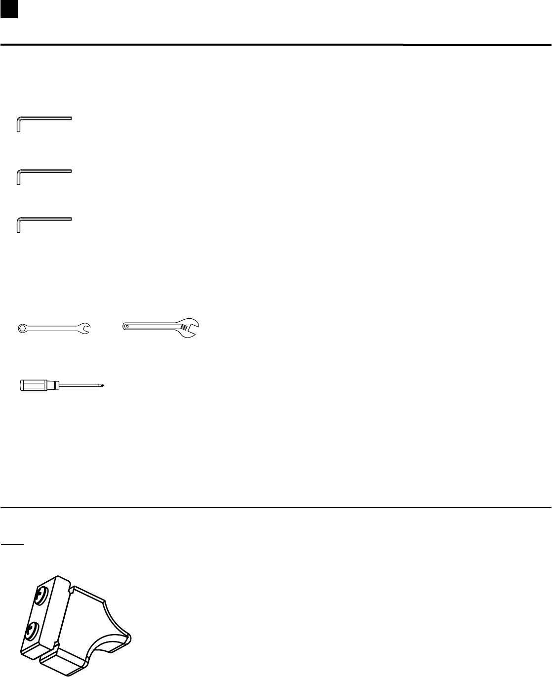
15 Tools You Will Need
Hex Wrenches Are Provided in the Box
3/16”HexKeyfor5/16”PanHeadAllenBolts:
7/32”HexKeyfor3/8”PanHeadAllenBolts:
5/32”HexKeyfor#10CapScrews:
These Tools Are Not Provided in the Box
Wrench(1/2”),(7/16”),(9/16”)and(3/4”)orAdjustableWrench
(not provided):
PhillipsHeadScrewdriver(not provided):
* Specifications subject to change without notice.
NOTE: THE ROD BOX RETAINER (WITH 2 PRE-INSTALLED
SCREWS) IS LOCATED ON THE HARDWARE CARD.
16
1TY 0AN(EAD!LLEN"OLTvXv
1TY 0AN(EAD!LLEN"OLTvXv
1TY 0AN(EAD!LLEN"OLTvXv
1TY 0AN(EAD!LLEN"OLTvXv
1TY 0AN(EAD!LLEN"OLTvXv
1TY 0AN(EAD!LLEN"OLTvXv
1TY 0AN(EAD!LLEN"OLTvXv
1TY 0AN(EAD!LLEN"OLTvXv
1TY
#AP3CREWS
Xv
1TY
"UTTON(EAD3CREWS
vXv
,OCATEDIN"OXHARDWAREBAG
1TY
0AN(EAD!LLEN"OLT
vXv
1TY7ASHERSv
1TY7ASHERSv
1TY7ASHERSv
%IGHTOFTHESEARELOCATEDIN
"OXHARDWAREBAG
1TY
.YLOCK.UTv
1TY
.YLOCK.UTv
4WOOFTHESEARELOCATED
IN!BBOXHARDWAREBAG
1TY
.YLOCK.UTv
1TY7ASHERSv
1TY7ASHERS
1TY
.UT
1TY
3ELF4APPING
3CREWS
Xv
1TY
#OACH3CREWS
Xv
1TY
3ELF4APPING
3CREWS
vXv
1TY
0AN(EAD
!LLEN"OLT
vXv
1TY 0AN(EAD!LLEN"OLTvXv
,OCATEDIN!B"OXHARDWAREBAG
1TY
3ELF4APPING
3CREWS
Xv
1TY
0INS
1TY
#AP3CREW
Xv
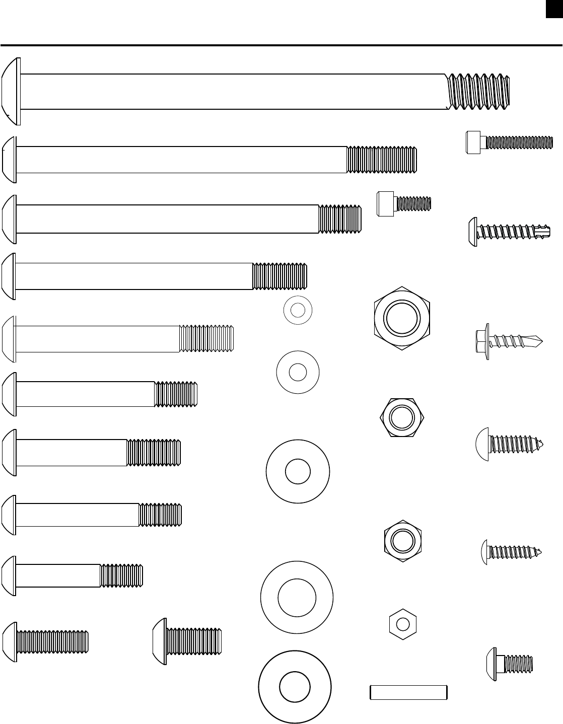
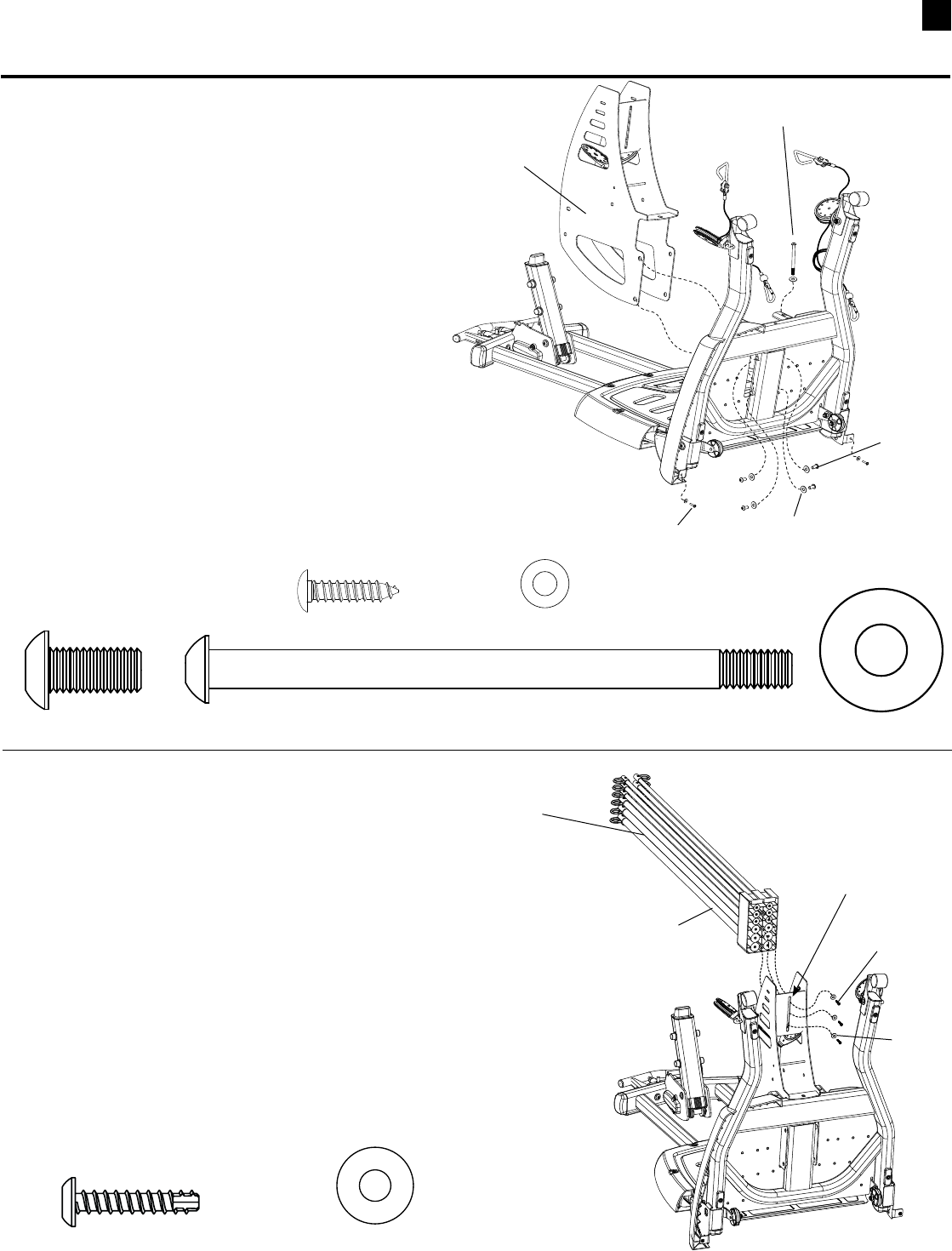
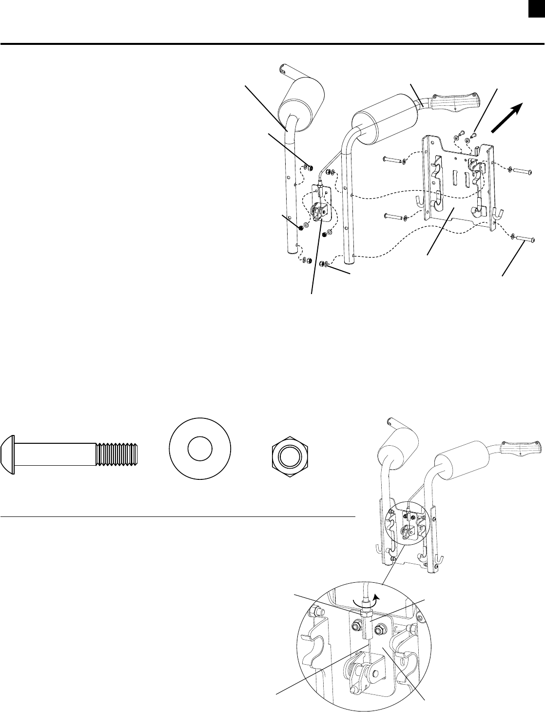
Hardware Chart (1:1 scale)
17
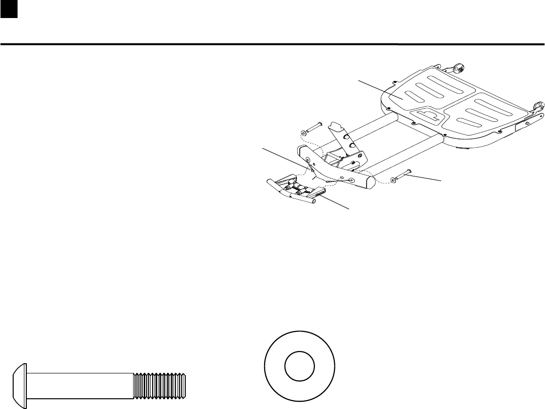
STEP 1
Parts:
•FrontBasePlatform(Box3)
•MetalHandleAssembly(Box3)
Tools:
•HexKey(7/32”)
1-1 Movetwisttiesandcableends
upandoutoftheway.
1-2 PositiontheMetalHandleAssembly(Labelside
up)ontheFrontBasePlatform.
1-3 Installandcompletelytightenthehardware.
2 Pan Head Allen Bolt (3/8” X 2 1/4”)
Hardware (1:1):
Metal Handle Assembly
Pan Head Allen Bolt
2 Washers (3/8”)
Cable Ends
Front Base Platform
Assembling Your Bowflex Ultimate® 2
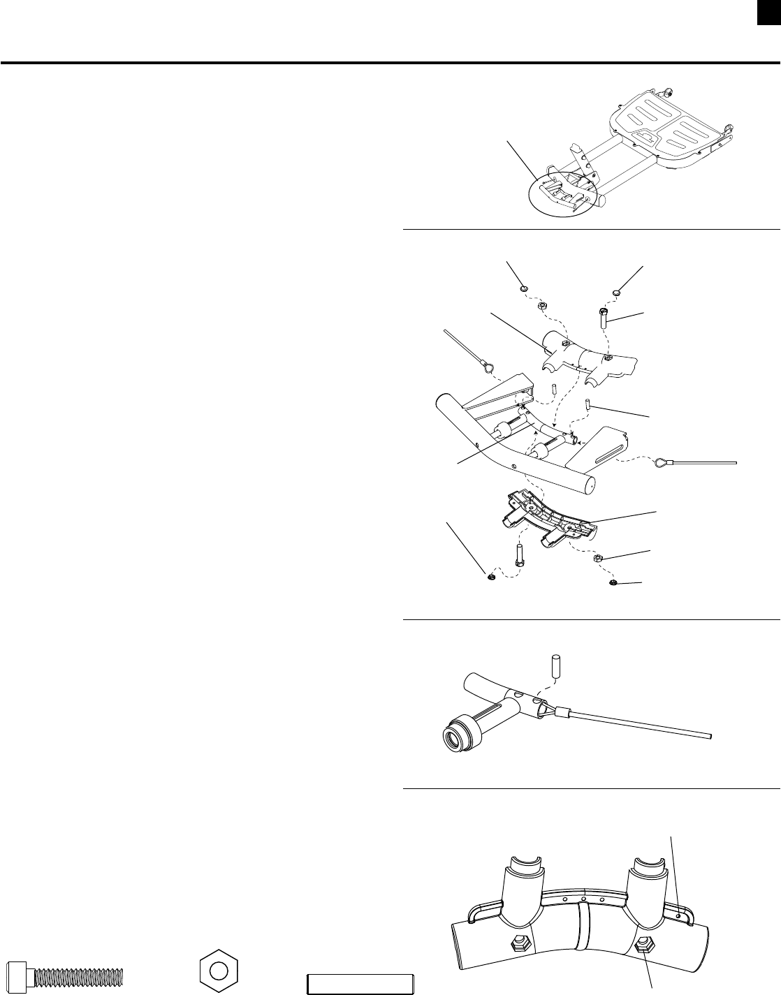
18
Assembling Your Bowflex Ultimate® 2
STEP 2
Parts:
•HandleandBaseAssembly(from Step 1)
•PlasticHandleTopandBottom
•CableRetainerPins(HardwareCard)
•PlasticPlugCovers
Tools:
•HexKey(5/32”)
2-1 LaytheHandleandBaseAssemblydownonthe
oor,removethePlasticPlugCoversand
separatetheTopandBottomofthePlasticHandle.
2-2 Remove the Twist Ties.
2-3 FeedcablesthroughMetalHandleandposition
theCableEndLoopjustinsidetheHollowTube.
You may have to slide the Hollow Tube toward
the Front Base to allow cables to reach.
2-4 InsertCableRetainerPinsthroughholeand
cable loop. (See Detail A)
2-5 PositionTopandBottomofPlasticHandle.
NOTE: The hexagonal holes in the left side of the
Handle are shallower than the holes in the right
side. The #10 Nuts go in the deeper hexagonal
holes on the right side of the handle. The right
side can be identified by noting a small hole in
the plastic flange. (See Detail B)
2-6 Installandcompletelytightenthehardware.
2-7 InstallPlasticPlugCoversoverhardware.
NOTE: The Plug Covers are marked on the inside with
an “N” or an “H”. To insure proper fit, use the
caps marked with an “N” to cover the nuts
and the caps marked with an “H” to cover the
screw heads.
Hardware (1:1):
2 Cap Screws (#10 X 1”) 2 Nut (#10)
Detail A
Cable Retainer Pin through
hole and Cable End Loop
Front Handle
Detail B
Note small hole in Handle
on Right side
Deeper Hole
Cap Screw
Plastic Plug Cover (H)
Cable Retainer Pin
Plastic Handle
To p
Plastic Handle
Bottom
Plastic Plug Cover (N)
Nut #10
Plastic Plug Cover (N)
Hollow Tube
2 5.27 Cable Retainer Pins
Plastic Plug Cover (H)
19 Assembling Your Bowflex Ultimate® 2
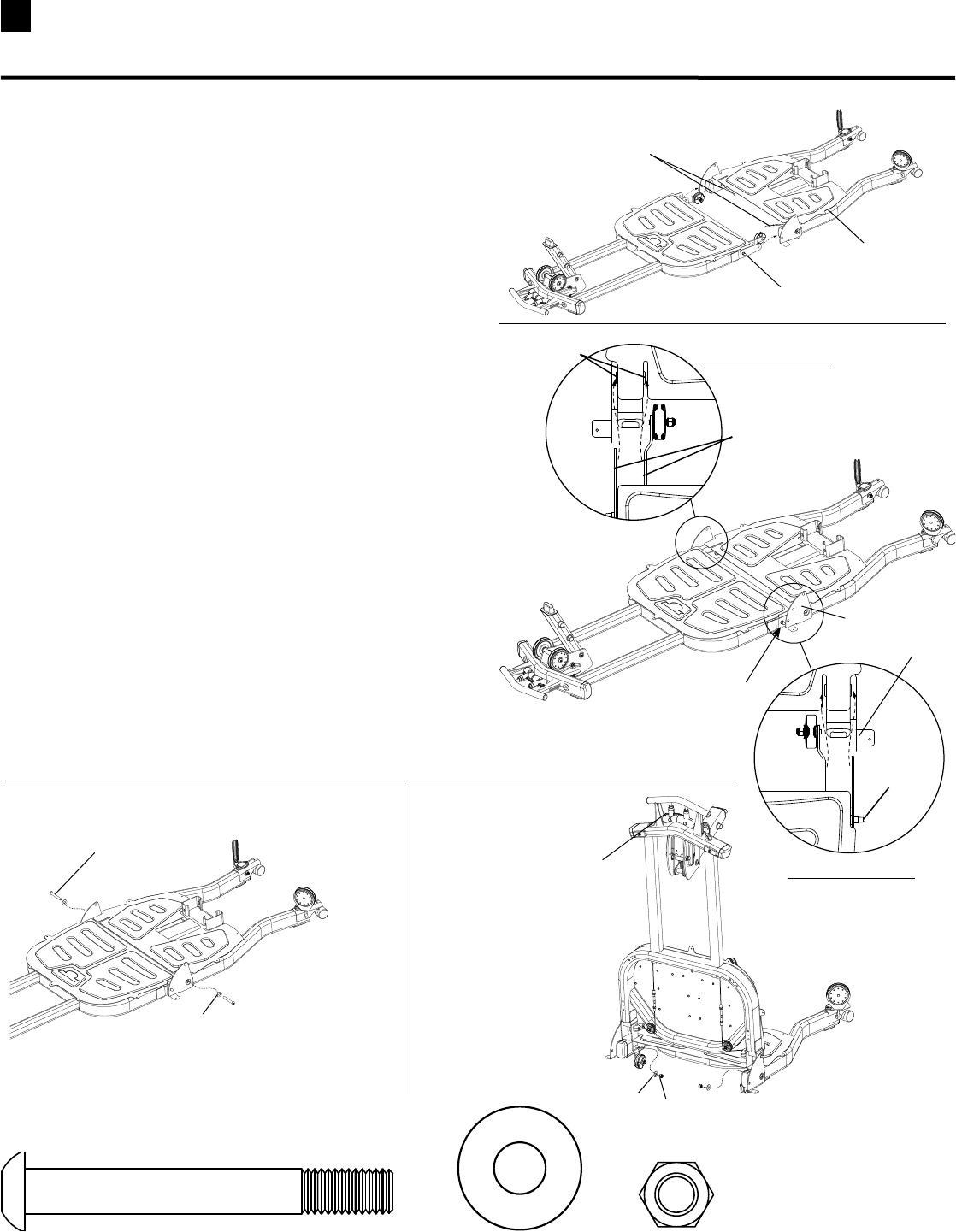
STEP 3 – Use two people for this step!
Parts:
•FrontBaseAssembly
•RearBasePlatform(Box2)
Tool:
•HexKey(7/32”)
•Wrench(9/16”)- or Adjustable Wrench
3-1 RemoveWireTiesfromBushings.
3-2 SlideFrontBasetowardrearbaseuntilthe
LockingPinsmakecontactwiththesideplates.
MAKE SUREtheFlangesslideovertheBushings
duringthisprocedure.(See Top Detail View)
3-3 SqueezetheFrontHandletoretracttheLocking
Pins,liftthehandleabout3-4inchesandpush
FrontBasecompletelyintotheRearBase.
ReleasethehandleandmakesuretheLocking
PinsprotrudethroughtheSidePlates.
3-4 InserttheButtonHeadBoltandWasherthen
squeezeFrontHandleandfoldFrontBaseupto
installInsideWasherandHexnut.Completely
tightenhardware.
2 Pan Head Allen Bolt (3/8” X 3”) 4 Washers (3/8”)
Hardware (1:1):
2 Nylock Nut (3/8”)
Remove Wire Ties
from Bushings
TOP DETAIL VIEW
Bushings
Make sure Flanges
slide over Bushings
TOP DETAIL VIEW
Slide Front Base
towards Back Base
Until it Contacts Pins
Locking Pin
Pan Head Allen Bolt
Washer
Squeeze Handle and
Fold Front Base up
to install Nylock Nut
and Washer
A
B
CD
Washer
Nylock Nut
Side Plate
Side Plate
Locking Pin
Rear Base
Platform
20
Assembling Your Bowflex Ultimate® 2
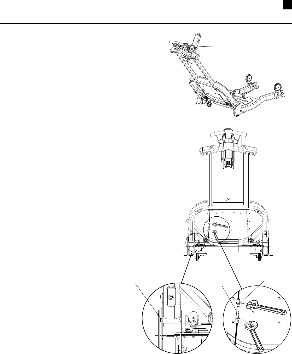
Cable Adjustment (Requires Two People)
1. Positionthebasesomewherebetweenthetwo
locking positions.
2. Pullthehandleuntilitisinthemostcompressed
position.
3. Placea1/4”oradjustablewrenchontheAdjusting
Barrelandusea1/4”oradjustablewrenchtoloosen
the locking nut. (See Detail B)
4. RotatetheAdjustingBarrelclockwisetoincrease
thecabletension.TheLockingPinsshouldbeas
closetotheSidePlatesaspossiblewithoutmaking
contact. (See Detail A)
5. Testtheadjustmentbyreleasingthehandleand
rotating the base to a locking hole. Make sure pin
securely engages with the locking hole then pull the
handleandmakesuretheunitmovesfreely.
6. Repeattheprocedureforbothsidesifnecessary.
7. TightenLockNutsagainstAdjustingBarrel.
The cables that retract the locking pins may
stretch with use. If the locking pins do not fully
retract or interfere with the side plates, make
the following adjustment.
Pull handle and position base
between the locking positions.
Detail A Detail B
Locking Nut
Adjusting Barrel
Make sure Locking Pin is as close
as possible without making
contact with Side Plate
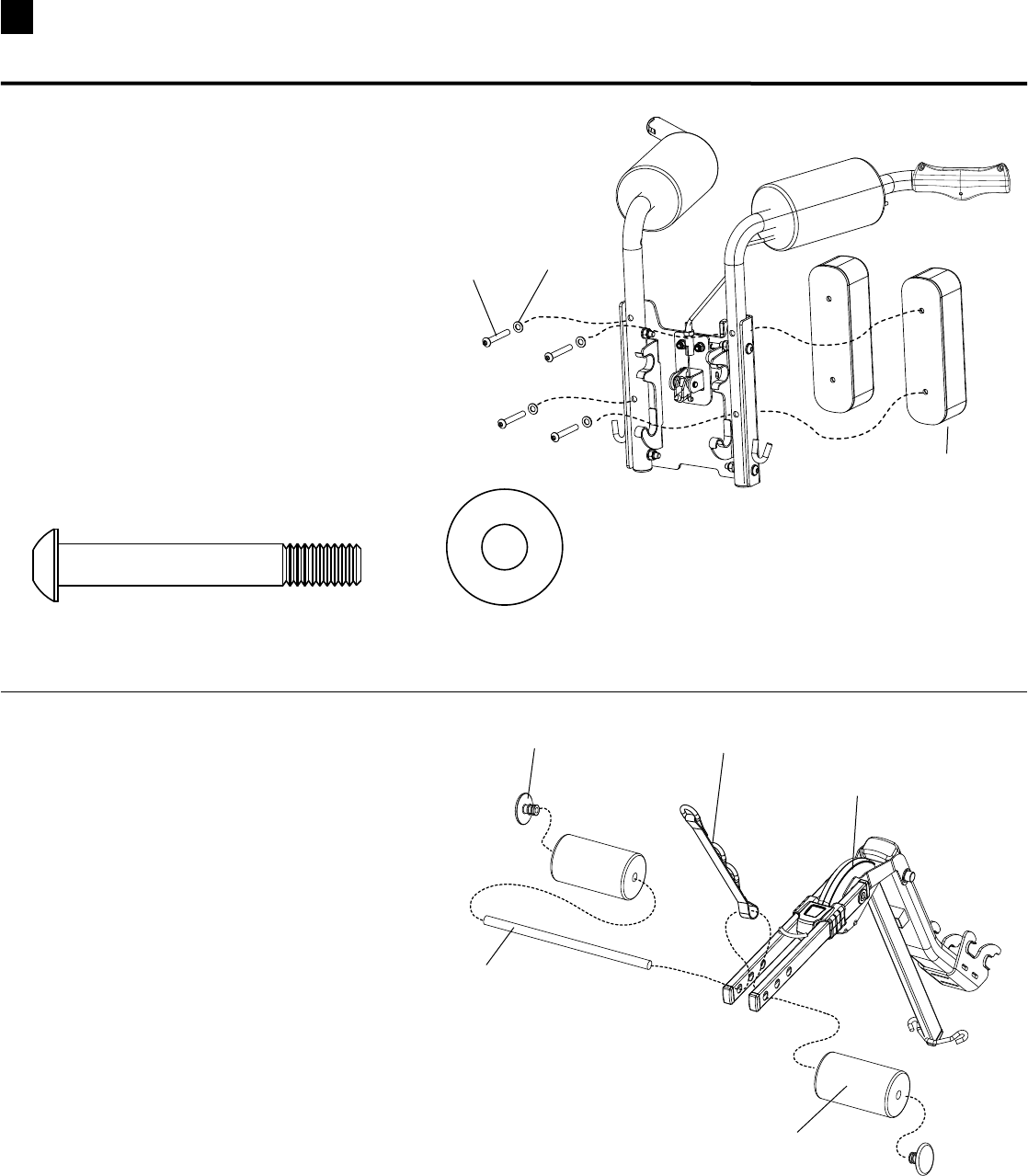
21 Assembling Your Bowflex Ultimate® 2
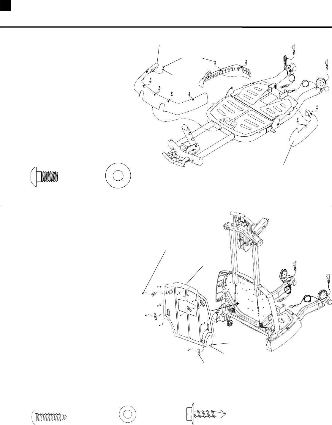
STEP 4
Parts:
•BaseAssembly(from step 3)
•Front&RearPlasticBaseCovers(Box2)
Tool:
•HexKey(7/32”)
4-1 PositionPlasticCoversonFrontand
RearBasePlatforms.
4-2 Installandcompletelytightenthehardware.
9 Pan Head Allen Bolt (1/4” X 1/2”) 9 Washers (1/4”)
Hardware (1:1):
Pan Head Allen Bolt
Washer
Rear Plastic Cover
STEP 5
Parts:
•BaseAssembly
•FrontBasePlate(Box3)
•FrontBaseFeet(4)(Box5)
Tools:
•Wrench(5/16”) •PhillipsHeadScrewdriver
5-1 Foldthefrontbaseassemblyintothe
upright position.
5-2 PositiontheBasePlateandsecurewith
eightPhillipsHeadScrewsandWashers.
5-3 PositionthefourBaseFeetandsecurewith
HexWasherHeadScrews.Do not over tighten.
Feet could crack with excess pressure!
5-4 CompletelytightentheBasePlatehardware.
Hardware (1:1):
Front Base Plate
Phillips Head Screw
Hex Washer Head Screw
Front Base Foot
Washer
8 Self Tapping Screws (#8 X 3/4”) 8 Washers (#8 ) 4 Coach Screws (#10 X 3/4”)
Front Plastic Cover
22
Assembling Your Bowflex Ultimate® 2
STEP 6
Parts:
•BaseAssembly
•RodBox(Box4)
Tools:
•HexKey(7/32”)
6-1 LeaveBaseinfoldedpositionandtiltforwardto
gainaccesstobottomofRearBase.
6-2 PlacetheRodBoxthroughRearBaseandalign
with holes in base frame.
6-3 Installthe43/4”screwrsttoholdtheRodBoxin
positiontheninstallthefour3/4”screws.
6-4 Installthetwo#8x3/4”screwstosecuretherear
basecovers.Completelytightenallthehardware.
4 Pan Head Allen Bolt (3/8” X 3/4”) 5 Washers (3/8”)
Hardware (1:1):
Pan Head Allen
Bolt 3/4”
Washer
Rod Box
Pan Head Allen Bolt
4 3/4”
1 Pan Head Allen Bolt (3/8” X 4 3/4”)
2 Self Tapping Screws (#8 X 3/4”) 2 Washers (#8)
#8 x 3/4” Self
Tapping Screw
STEP 7 (Requires Two People)
Parts:
•BaseAssembly
•RodPack(Box1)
Tools:
•PhillipsHeadScrewdriver
7-1 LeaveBaseinfoldedpositionfromstep6.
7-2 HaveonepersonaligntheRodPackwiththeslot
intheRodBoxwiththe50Lb.rodsfacingdown.
7-3 HavesecondpersonInstallandcompletely
tightenhardware.
3 Self Tapping Screws (#10 X 1”)
Hardware (1:1):
Rod Pack
Self Tapping
Screw
Washer
50 Lb. Rods
facing down
Align with slot
in Rod Box
3 Washers (1/4”)
23 Assembling Your Bowflex Ultimate® 2
Unscrew
Figure B
Figure C
Insert into slot of
Rod Box Frame
Rod Box
Backing Plate
Qty:2
SelfThreadingScrews(#10x1”)
Rod Box Retainer (screws are pre-installed)
Notched Lip
Curved Side
Backing
Plate
Face
Place
STEP 7B
Parts:
•1RodBoxRetainer
Tool :
•PhillipsHeadScrewDriver
Note: RodBoxscrewsmustbeinstalledbefore
proceeding.
7B-1 Remove both screws connecting the backing
plateandthefaceplate(SeeFigureA).
7B-2StandfacingtherearoftheBowflexUltimate®2
unit.Placethebackingplate(largerpiece),withthe
curvedsidefacingup,inbetweenthetworight-side
50lb.rods(SeeFigureB).Verifythatthenotchedlip
ofthebackingplateislocatedintheslotoftheBox
Frame.
7B-3Matchupthefaceplate(thinnerpiece)tothebacking
plateontheoutsideoftherodbox.Makesurethat
thenotchedlipofbothbackingplatesaretouching
andthattheholesarealigned.
7B-4Fastenbothscrewsintothelinedupholes(See
FigureC).Tightenuntilsnugandthenanother
quarterturn.
Figure A
Face Plate
After installing the Rod Box in Step 7, install the Rod Retainer.
24
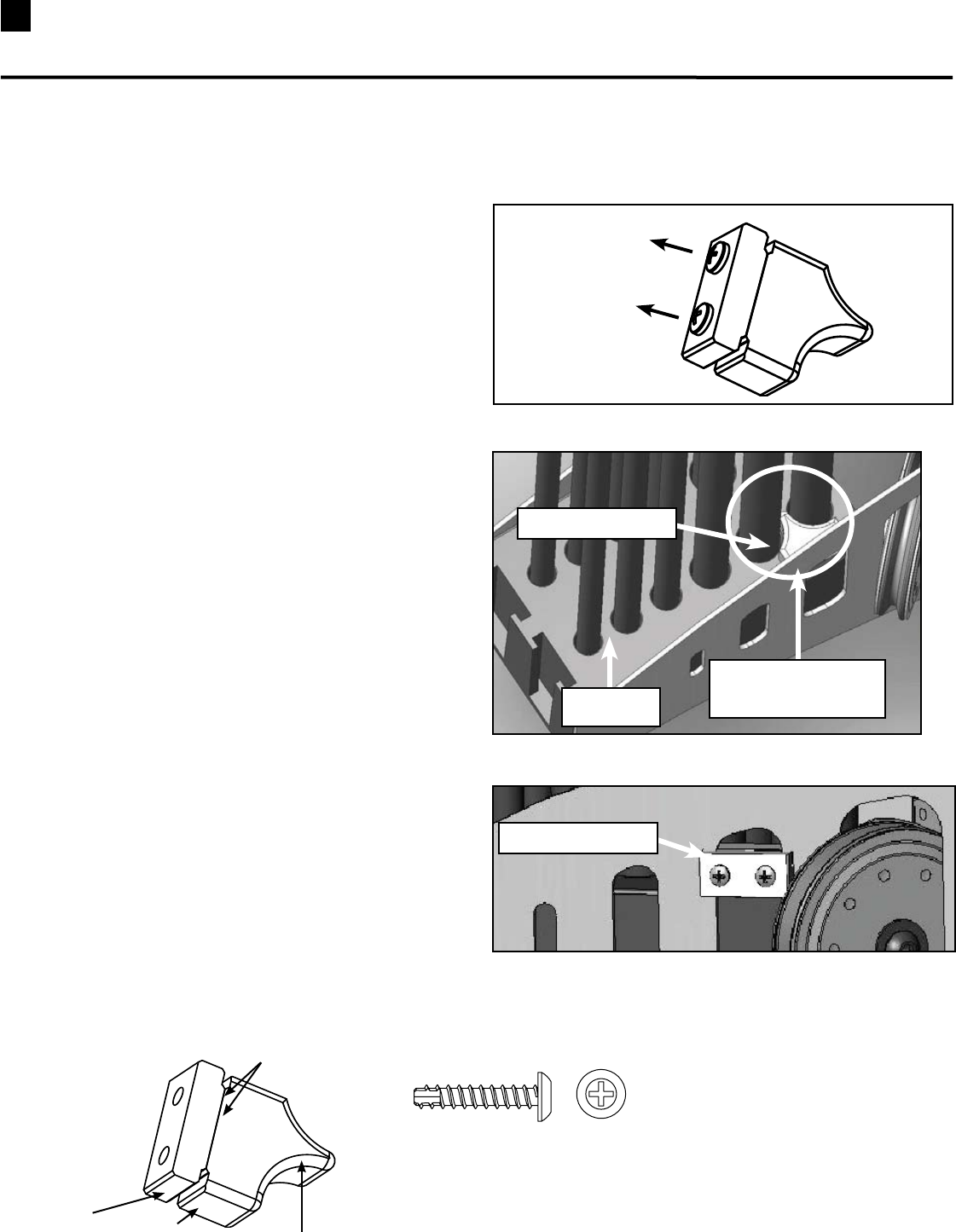
Assembling Your Bowflex Ultimate® 2
STEP 8
Parts:
•LowerLatTowerUprights(Box4)
•SquatHolder(Box4)
•CrossBrace(Box4)
Tool:
•HexKey(7/32”)
8-1 InsertCrossBraceandSquatHolderintoLower
LatTowerUprights.MakesuretheSquatHolder
faces the the front of the Uprights. The label is on
the front and the screw holes are on the back of
the holder.
8-2 Install but do not tighten thehardwareuntil
Step9.
Hardware (1:1):
Squat Holder
Pan Head Allen
Bolt
2 Pan Head Allen Bolt (3/8” X 3/4”) 2 Washers (3/8”)
8 Washers (3/8”)
Hardware (1:1):
STEP 9
Parts:
•LowerLatTowerAssembly(from step 8)
•BaseAssembly
Tools:
•HexKey(7/32”)
•Wrench(9/16”) - or Adjustable Wrench
9-1 PlaceLowerLatToweroverextrusionson
BaseAssembly.
9-2 Installandcompletelytightenthehardware
fromsteps8and9.
Pan Head Allen Bolt
3/4”
Lower Lat Tower
Assembly
Washer
Pan Head Allen Bolt
2 1/2”
Nylock Nut
4 Pan Head Allen Bolt (3/8” X 3/4”) 2 Pan Head Allen Bolt (3/8” X 2 1/2”) 2 Nylock Nuts (3/8”)
(Rod Pack Not Shown
For Clarity)
Label
The Cross Brace is on the
front of the Uprights
Cross Brace
(Do Not Tighten The Hardware For This Step Until Step 9 )
Lower Lat Tower Uprights
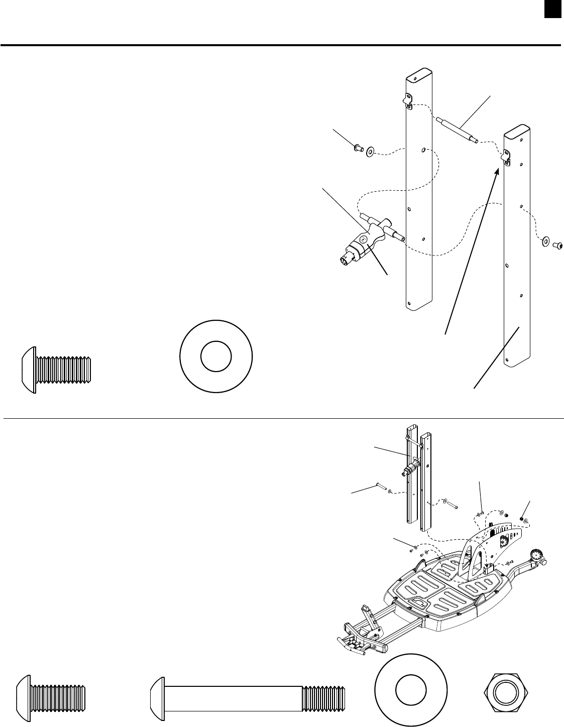
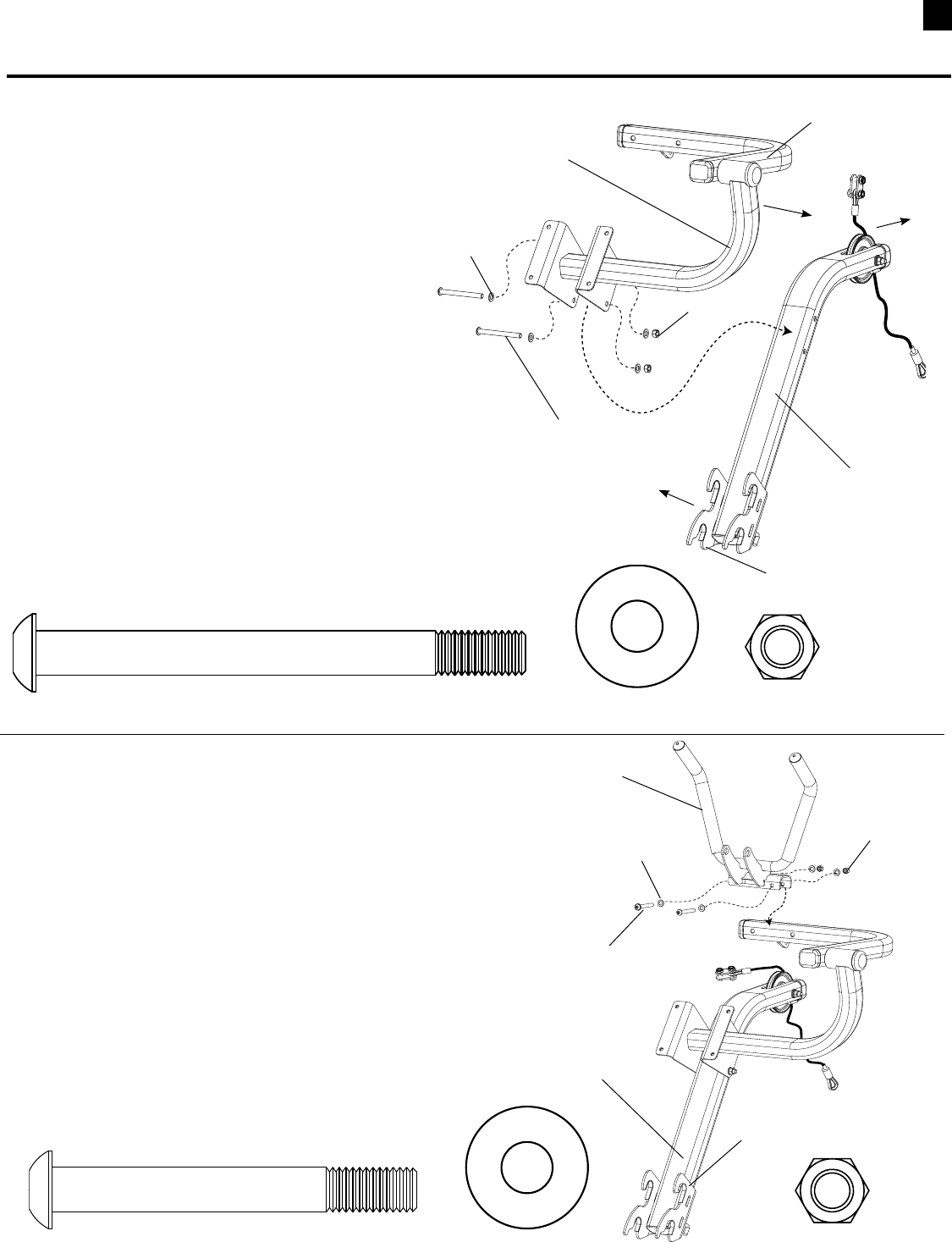
25 Assembling Your Bowflex Ultimate® 2
STEP 10
Parts:
•SeatRailAssembly(Box5)
•BaseAssembly
Tool:
•HexKey(7/32”)
•Wrench(9/16”) - or Adjustable Wrench
10-1 Align holes on Seat Rail with holes
inRodBoxAssembly.
10-2Installandcompletelytightenthehardware.
1 Pan Head Allen Bolt (3/8” X 5 1/2”) 2 Washers (3/8”)
Hardware (1:1):
Pan Head Allen
Bolt
Washer
Hex Nut
Seat Rail Assembly
Rod Box
Assembly
4 Washers (1/2”)
Hardware (1:1):
Pan Head Allen
Bolt Washer
Hex Nut
Chest Bar
Pulley Slider
2 Pan Head Allen Bolt (1/2” X 6 3/4”)
2 Nylock Nut (1/2”)
STEP 11
Parts:
•ChestBar(Box4)
•PulleySliders(Box4)
•WasherPlate(Box4)
Tools:
•HexKey(5/16”)
•Wrench(3/4”)- or adjustable wrench
11-1 AlignholesinChestBar,WasherPlateandLatTower
Uprights.
11-2 InstallandcompletelytightentheChestBarhardware.
11-3
SlidethePulleySliderson(withpulleysfacingupandpull
knobfacingtheseatrail)theninstallandtightenthe
1/4”x1/2”StopScrews.
Washer Plate
(Rod Pack Not Shown
For Clarity)
Stop Screw
1 Nylock Nut (3/8”)
(Rod Pack Not Shown
For Clarity)
2 Cap Screw (1./4 x 1/2”)
26
Assembling Your Bowflex Ultimate® 2
STEP 12
Parts:
•LeftLatBoom(Box6)
•RearPulleyFrame(Box6)
•SidePlate(Box4)
Tool:
•HexKey(3/16”)
12-1 InsertRearPulleyFrameinto
holesinLeftLatBoom.
Make sure the Pulley Frame
Swivel is parallel to the planes
A and B shown in the Side View.
12-2AlignholesinSidePlateandLatBoom.
12-3 Install but do not tightenhardware.
Hardware (1:1):
2 Pan Head Allen Bolt (3/8” X 3/4”) 2 Washers (3/8”)
Pan Head Allen
Bolt
Washer
Left Lat Boom
Side Plate
Rear Pulley
Frame
STEP 13
Parts:
•PulleyFrameBoomAssembly(from step 12)
•LatBar(Box6)
Tool:
•HexKey(3/16”)
13-1 InsertleftsideofLatBarintoLeftBoom.
13-2 Install but do not tightenhardware.
1 Pan Head Allen Bolt (3/8” X 3/4”) 1 Washer (3/8”)
Hardware (1:1):
Pulley Frame, Left Boom
Assembly
Lat Bar
Pan Head Allen
Bolt
Washer
CORRECT
INCORRECT
Plane A Plane B
Plane A Plane B
Swivel
Swivel
Side View
NOTE: Before you continue, be sure you have a minimum of 88” (7’4”) of ceiling height to insert the
Upper Lat Assembly into the Lower Base (see step 17).
27 Assembling Your Bowflex Ultimate® 2
STEP 14
Parts:
•LatBar,BoomAssembly(From step 13)
•RightLatBoom(Box6)
•SidePlate(Box4)
Tool:
•HexKey(3/16”)
14-1AlignholesinRightLatBoomwithRearPulley
FrameCrossBarsandinsertrightsideofLatBar
andPulleyFrameCrossBarsintoRightLatBoom.
14-2AlignSidePlatewithRightLatBoomandinstall
but do not tightenhardware.
3 Pan Head Allen Bolt (3/8” X 3/4”) 3 Washers (3/8”)
Hardware (1:1):
Right Side
of Lat Bar
Right Lat Boom
Pan Head Allen
Bolt
Washer
Pulley Frame
Cross Bars
STEP 15
Parts:
•LatBar,BoomAssembly(From step 14)
•TopPlate(Box6)
Tools:
•HexKey(3/16”)
•PhillipsHeadScrewdriver
15-1 AlignholesinTopPlatewithLatBarandBooms.
15-2 Install but do not tightenhardware.
2 Pan Head Allen Bolt
(3/8” X 3/4”) 2 Washers (3/8”)
Hardware (1:1):
5 Self Tapping Screws
(1/4” X 3/4”)
Washer
Pan Head Allen Bolt
Pan Head
Screw
Top Plate
5 Washers (1/4”)
Side Plate
28
Assembling Your Bowflex Ultimate® 2
STEP 16
Parts:
•LatBoomAssembly(from step 15)
•UpperLatUprights(Box6)
Tool:
•HexKey(7/32”)
•Wrench(9/16”)- or Adjustable Wrench
16-1 SlideUpperLatUprightsontoLatBoomassembly
16-2 Install but do not tightenthetwo3/8”x3/4”screws
into the top of the uprights.
16-3 Installthetwo3/8”x21/4”Screws,Washersand
NylockNutthroughtheSidePlatesandintothe
Uprights.
16-4 Completelytightenallofthehardwareforsteps
12through16.
2 Pan Head Allen Bolt (3/8” X 3/4”) 6 Washers (3/8”)
Hardware (1:1):
2 Pan Head Allen Bolt (3/8” X 2 1/2”)
Pan Head Allen Bolt
3/8” x 3/4”
Pan Head Allen Bolt
3/8” x 2 1/2”
Washer
Washer
Upper Lat Uprights
2 Nylock Nut (3/8”)
Washer
Hex Nut
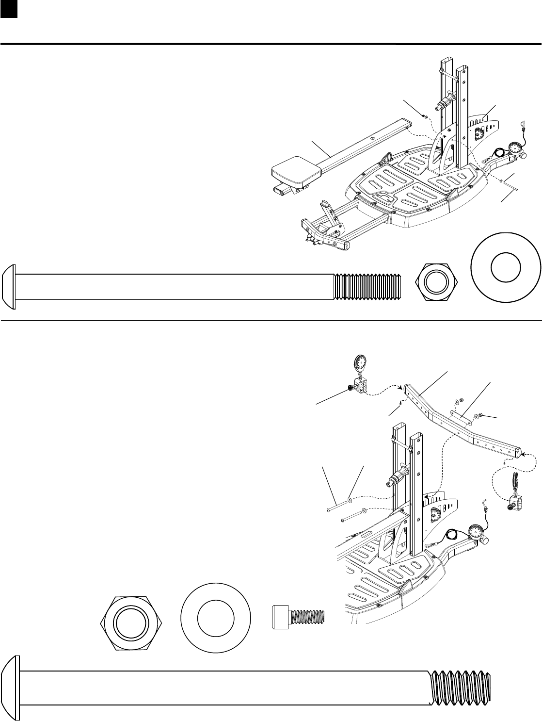
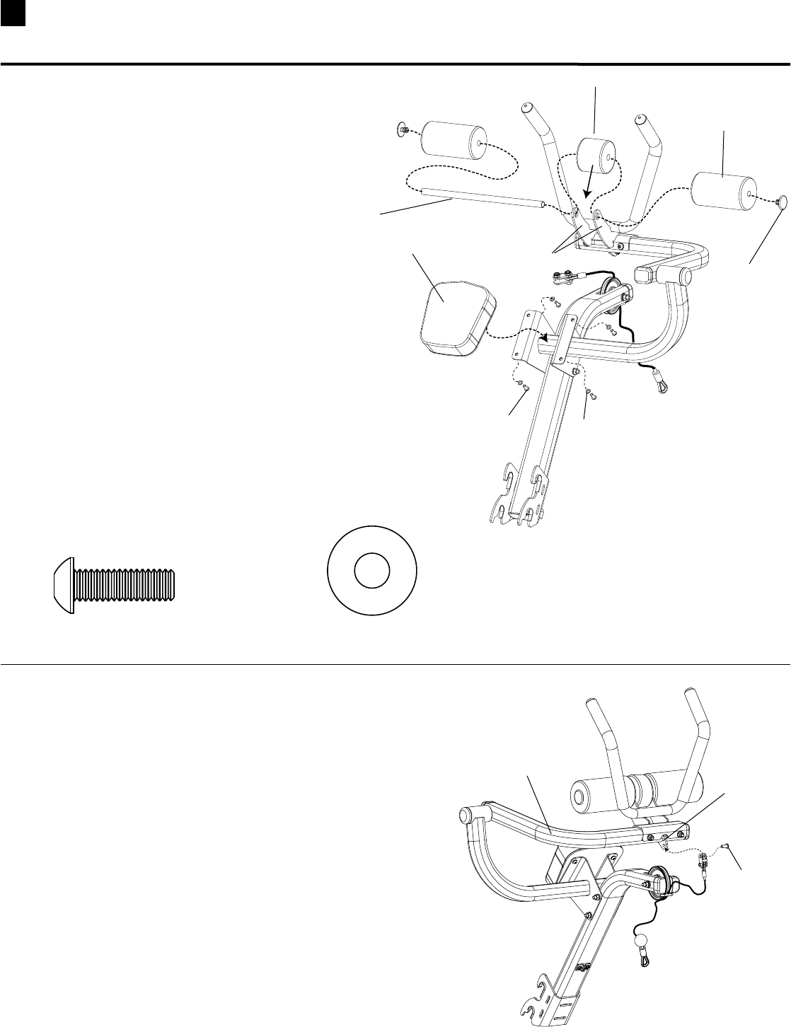
29 Assembling Your Bowflex Ultimate® 2
STEP 17 – Upper Assembly is very heavy!
Use two people for this step!
Parts:
•UpperLatAssembly(from step 16)
•BaseAssembly(from step 11)
Tool:
•HexKey(7/32”)
17-1 InsertUpperLatUprightsintoLowerLatUprights.
17-2 Installandcompletelytightenthehardware.
Hardware (1:1):
Upper Lat Assembly
Base Assembly
8 Pan Head Allen Bolt (3/8” X 3/4”) 8 Washers (3/8”)
STEP 18
Parts:
•FrontFacePlate(Box6)
•AssembledUnit(from step 17)
Tool:
•HexKey(7/32”)
18-1 AlignholesinFacePlateandUprights.
18-2 Installandcompletelytightenhardware.
Hardware (1:1):
4 Pan Head Allen Bolt (3/8” X 3/4”) 4 Washers (3/8”)
Pan Head Allen
Bolt
Washer
Lat Tower Uprights
Pan Head Allen
Bolt
Washer
Front Face Plate
(Rod Pack Not Shown
For Clarity)
(Rod Pack Not Shown
For Clarity)
30
Assembling Your Bowflex Ultimate® 2
STEP 19
Parts:
•SquatFrame(Box2)
•ShoulderBars(Box2)
Tool:
•HexKey(3/16”)and(5/32”)
•Wrench(1/2”)&(7/16”)- or Adjustable Wrench
19-1 PositionShoulderBarsagainstbackof
SquatFramewithbendinarmspointing
towardsthefrontoftheframe.
19-2 Installandcompletelytightenthesidescrews,
washersandnylocknuts.
19-2 RemovethehardwaresecuringtheLockPin
AssemblytotheSquatFrame.
19-3 AlignholesinLockPinAssemblyand
SquatFrame.
19-4Re-installandcompletelytightenLockPin
Assemblyhardware.
Hardware (1:1):
Left Shoulder Bar
Front
Right Shoulder Bar
(has handle and cable)
Side Screw
Button Head (5/16” x 1 3/4”)
Squat Frame
Lock Pin Assembly
1/4” Nylock Nut
Washer
Button Head Screw
(1/4” x 3/4”)
5/16” Nylock Nut
4 Pan Head Allen Bolt (5/16” X 1 3/4”) 8 Washers (5/16”)
Cable Adjustment
The Release Cable should be adjusted so
that there is enough tension to keep the
cable from laying on the metal frame. In
most cases this adjustment will be fine out
of the box. If the cable needs adjustment,
loosen the locknut and turn the Adjusting
Barrel counter-clockwise until cable is taut.
The release cable may stretch with use.
Check the cable tension regularly and
adjust if needed.
Metal Frame
Release Cable
Adjusting Barrel
Lock
Nut
4 Nylock Nut (5/16”)
31 Assembling Your Bowflex Ultimate® 2
STEP 21
Parts:
•LegExtensionPivotArmAssembly(Box7)
•RollerPads(Box7)
•WebbingwithSteelRing(Box7)
•RollerShaft(Box7)
•EndCaps(Box7)
21-1 Insert Roller Shaft through hole in one of
therectangulararms.PlacetheWeb-
bing with Steel Rings between the two
rectangulararms,andcontinuetoslide
theShaftthroughtheWebbingandhole
in opposite arm.
21-2 SlideRollerPadsandEndCapsontoRollerShaft. Roller Pad
Roller Shaft
Leg Extension Pivot Arm
Assembly
Webbing with Steel Rings
STEP 20
Parts:
•SquatAssembly(from step 19)
•SquatBackPads(Box2)
Tool:
•HexKey(3/16”)
20-1 AlignholesinSquatBackPadsand
SquatAssembly.
20-2 Installandcompletelytightenhardware.
Hardware (1:1):
4 Pan Head Allen Bolt (5/16” X 2 1/4”) 4 Washers (5/16”)
Pan Head Allen
Bolt Washer
Squat Back
Pad
End Cap
32
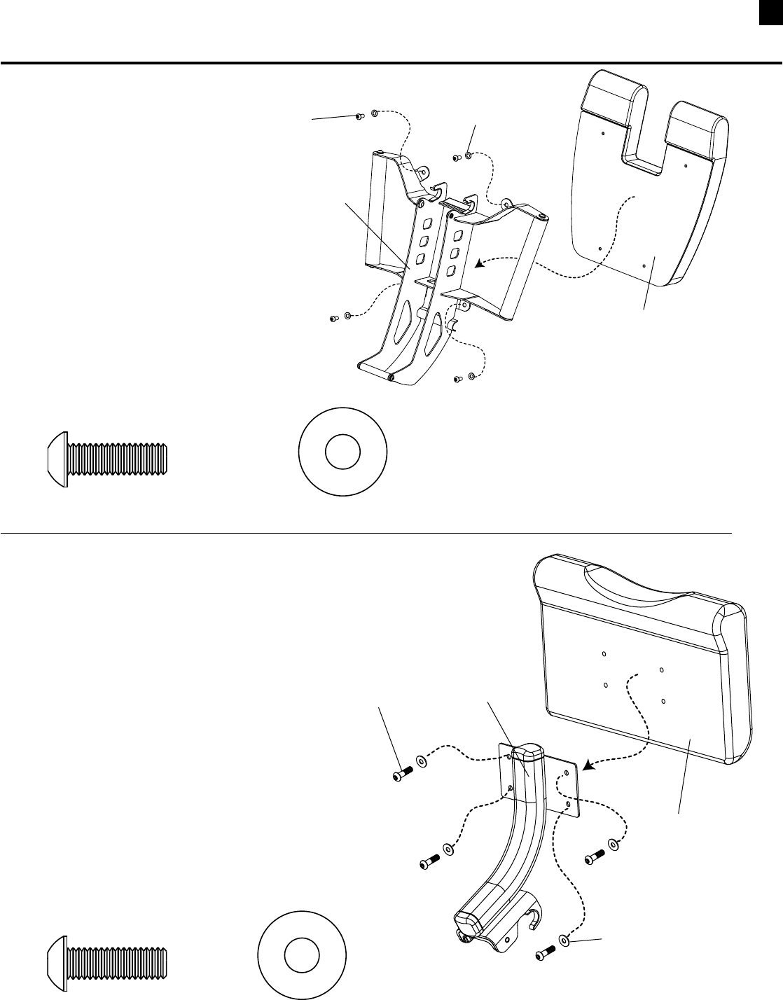
Assembling Your Bowflex Ultimate® 2
STEP 22 (optional attachment)
Parts:
•AbCrunchFrame(AbBox)
•AbCrunchPivotArm(AbBox)
Tool:
•HexKey(7/32”)
•Wrench(9/16”)- or Adjustable Wrench
22-1 PlaceAbCrunchFrameonoorwithhooks
onthetopandpulleyendpointingaway
from you.
22-2 AlignAbCrunchPivotArmonAbCrunch
Frame with the pivot mechanism to the right
sideasshown.
22-3Installandcompletelytightenhardware.
Hardware (1:1):
2 Pan Head Allen Bolt (3/8” X 4”) 4 Washers (3/8”)
Hooks on top
Pulley
pointing
away
Pivot Arm pointing to right
Pan Head Allen
Bolt
Washer
Nylock Nut
Ab Crunch Frame
2 Nylock Nuts (3/8”)
STEP 23
Parts:
•AbCrunchAssembly(from step 21)
•AbHandleBars(AbBox)
Tool:
•HexKey(7/32”)
•Wrench(9/16”)- or Adjustable Wrench
23-1 PlacetheAbHandleBarsontheAbPivotArmwith
theHandleBarspointingtowardthesamesideas
the hooks on the Ab Frame as shown.
23-2Installandcompletelytightenhardware.
Hardware (1:1):
2 Pan Head Allen Bolt (3/8” X 3”) 4 Washers (3/8”) 2 Nylock Nut (3/8”)
Pan Head Allen
Bolt
Washer
Nylock Nut
Hooks
Ab Frame
Ab Handle Bars
HardwareforthisstepisinthehardwarebagintheABBOX.
Hardwareforthisstepisinthehardware
bagintheABBOX.
Ab Crunch Pivot
Arm
33 Assembling Your Bowflex Ultimate® 2
STEP 25
Parts:
•AbCrunchAssembly(from step 23)
Tool:
•Wrench(1/2”)- or Adjustable Wrench
25-1 Undothe1/2”boltfromthebracketattheupper
endofthecableandusethesame1/2”boltto
attachthebrackettothetabonthePivotArm.
Ab Pivot Arm
Ta b
Bolt
STEP 24
Parts:
•AbCrunchAssembly(from step 22)
•AbBackPad(AbBox)
•RollerPads(AbBox)
•MiddlePad(AbBox)
•RollerPadShaft(AbBox)
•EndCaps(AbBox)
Tool:
•HexKey(3/16”)
24-1 PlacetheMiddlePadbetweenthearmsonthe
bracket.SlidetheRollerPadShaftthroughbracket
andtheMiddlePadtheninstallRollerPadsand
EndCaps.
24-2 AligntheAbBackPadwiththewiderendpointing
towardtheHandlebars.
24-3 Installandcompletelytightenhardware.
Hardware (1:1):
4 Pan Head Allen Bolt (5/16” X 1”) 4 Washers (5/16”)
Pan Head Allen Bolt Washer
Ab Back Pad
Roller Pad
End Cap
Roller Pad
Shaft
Middle Pad
Bracket Arms
Hardwareforthisstepisinthe
hardwarebagintheABBOX.
34
Assembling Your Bowflex Ultimate® 2
STEP 26
Parts:
•SeatFrame(Box7)
•LegExtensionSeatPad(Box7)
Tool:
•HexKey(3/16”)
26-1 AlignholesinLegExtensionSeatPad
andSeatFrame.
26-2 Installandcompletelytightenhardware.
Hardware (1:1):
4 Pan Head Allen Bolt (5/16” X 1”) 4 Washers (5/16”)
Pan Head Allen
Bolt Washer
Leg Extension
Seat Pad
Seat Frame
STEP 27
Parts:
•PreacherCurlFrame(Box7)
•PreacherCurlPad(Box7)
Tool:
•HexKey(3/16”)
27-1 AlignholesinPreacherCurlPadand
PreacherCurlFrame.
27-2 Installandcompletelytightenhardware.
Hardware (1:1):
4 Pan Head Allen Bolt (5/16” X 1”) 4 Washers (5/16”)
Pan Head Allen
Bolt
Washer
Preacher Curl
Pad
Preacher Curl
Frame
Assembling Your Bowflex Ultimate® 2
Hardwareforthisstepisinthe
hardwarebaginBOX7
Hardwareforthisstepisinthe
hardwarebaginBOX7
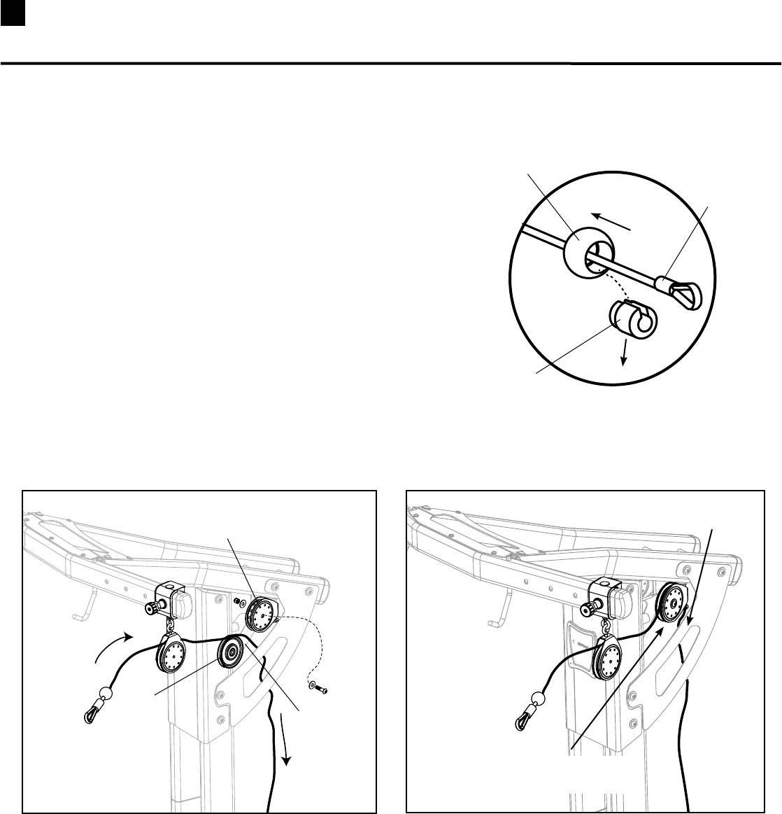
35 Installing Your Bowflex Ultimate® 2 Cables
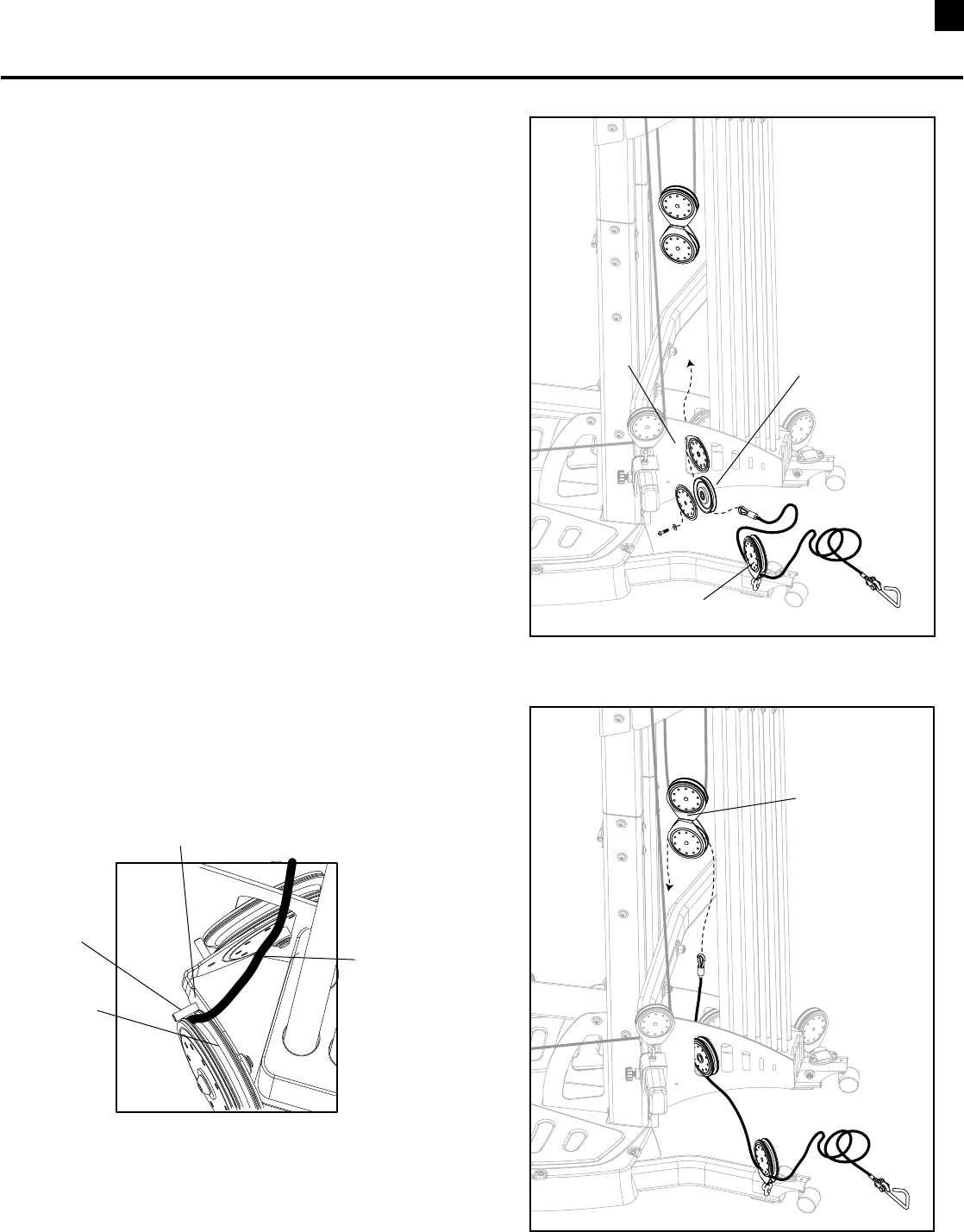
Cable Installation STEP 1
a. UncoilcablefromUpperPulleySlider.
b. RemoveBallStopfromtheendofcablethatisto
beroutedthroughpulleysbyslidingtheouterball
backfromthecableendandpushingouttheslotted
insert.Slidetheballoffofthecableandsetaside.
(See Figure A)
c. RemovethepulleyfromtheUpperPulleyBracket,
wrap the cable over the pulley (See Figure B)and
reinsertthepulleybackintotheUpperPulley
Bracket.MakesurethecableisinsidetheSide
PlatebeforemovingontoSTEP2.(See Figure C)
Slide Ball Back
Remove Slotted Insert
Cable End
Remove Pulley from
Upper Pulley Bracket
Pulley
Route Cable
Over Pulley
Replace Pulley and Hardware
with Cable
Cable Routed Inside
Side Plate
Figure B Figure C
Figure A
Tool:
•HexKey(7/32”)
•Wrench(9/16”)- or Adjustable Wrench
36
Cable Installation STEP 2
a. InBox4LocateaFloatingPulleyAssemblyanda
SinglePulleyAssemblywithtwoCheeks.
(See Figure A)
b. FeedthecablethroughtheFloatingPulleyAssembly.
(See Figure B)
c. RoutethecablebehindtheSidePlateandwrapover
theSinglePulleyAssembly.(See Figure C)
d. InstallSinglePulleywithcableonthebacksideof
theLatTowerasshown.(See Figure D)
Figure A
Route Cable Through
Floating Pulley Assembly
Figure B
Route Cable Through
Behind Side Plate
Wrap Cable Over
Single Pulley Assembly
Pan Head Al-
len Bolt
Washer
Tool:
•HexKey(7/32”)
Figure C
Figure D
(Rod Pack Removed For Clarity)
Installing Your Bowflex Ultimate® 2 Cables
Floating Pulley Assembly Single Pulley Assembly
Cheeks
Button Head Screw
Washer
Pulley
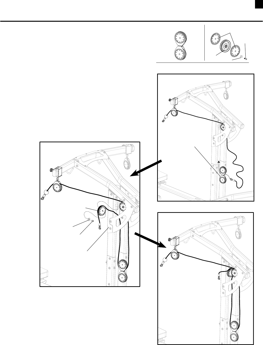
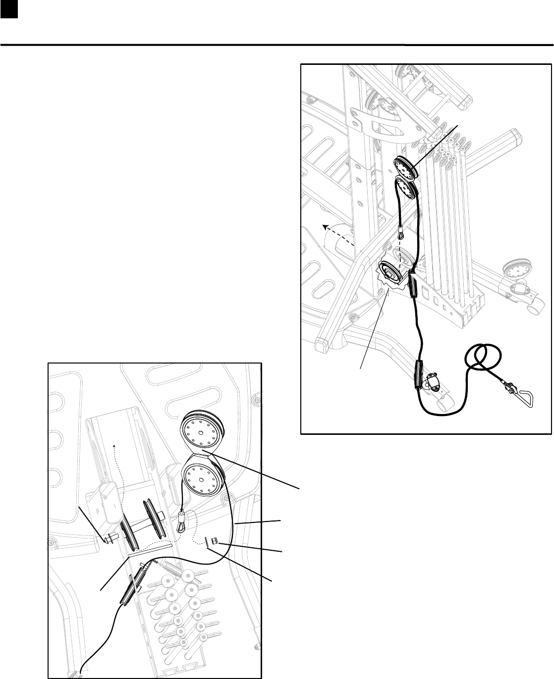
37 Installing Your Bowflex Ultimate® 2 Cables
Cable Installation STEP 3
a. RouteCabledownandthreadthroughPulley
SlideronChestBar.(See Figure A)
b. ReplacetheBallStop.(See Figure B and C)
Figure A Figure B
Slide Ball tightly against
Insert and Cable End
Replace Slotted Insert
Cable End
Figure C
Pulley Slider
Chest Bar
Ball Stop
Slotted Insert
(Rod Pack Removed For Clarity ) (Rod Pack Removed For Clarity )
38
Cable Installation STEP 4
a. UncoiltheCablefromLowerPulleyandremovethe
BallStop.(See Step 1/Figure A)
b. InBox4,locateaSinglePulleyAssemblywithone
Cheek.WraptheCableunderthePulleyandfeedthe
CablethroughtheholeintheRodBox.(See Figure A)
c. InstalltheSinglePulley(See Figure B) making sure
thecableisbetweenthePulleyandthesmallMetal
PostonthePulleyBracket.
(See Top View of Angled Pulley)
d. FeedtheCablethroughthelowerhalfoftheFloating
PulleyAssembly.
Tool:
•HexKey(7/32”)
Figure A
Figure B
Top View of
Angled Pulley
Pulley Bracket
Metal Post
Cable
Pulley
Floating Pulley
Assembly
Single Pulley
Rod Box
Lower Pulley
Installing Your Bowflex Ultimate® 2 Cables
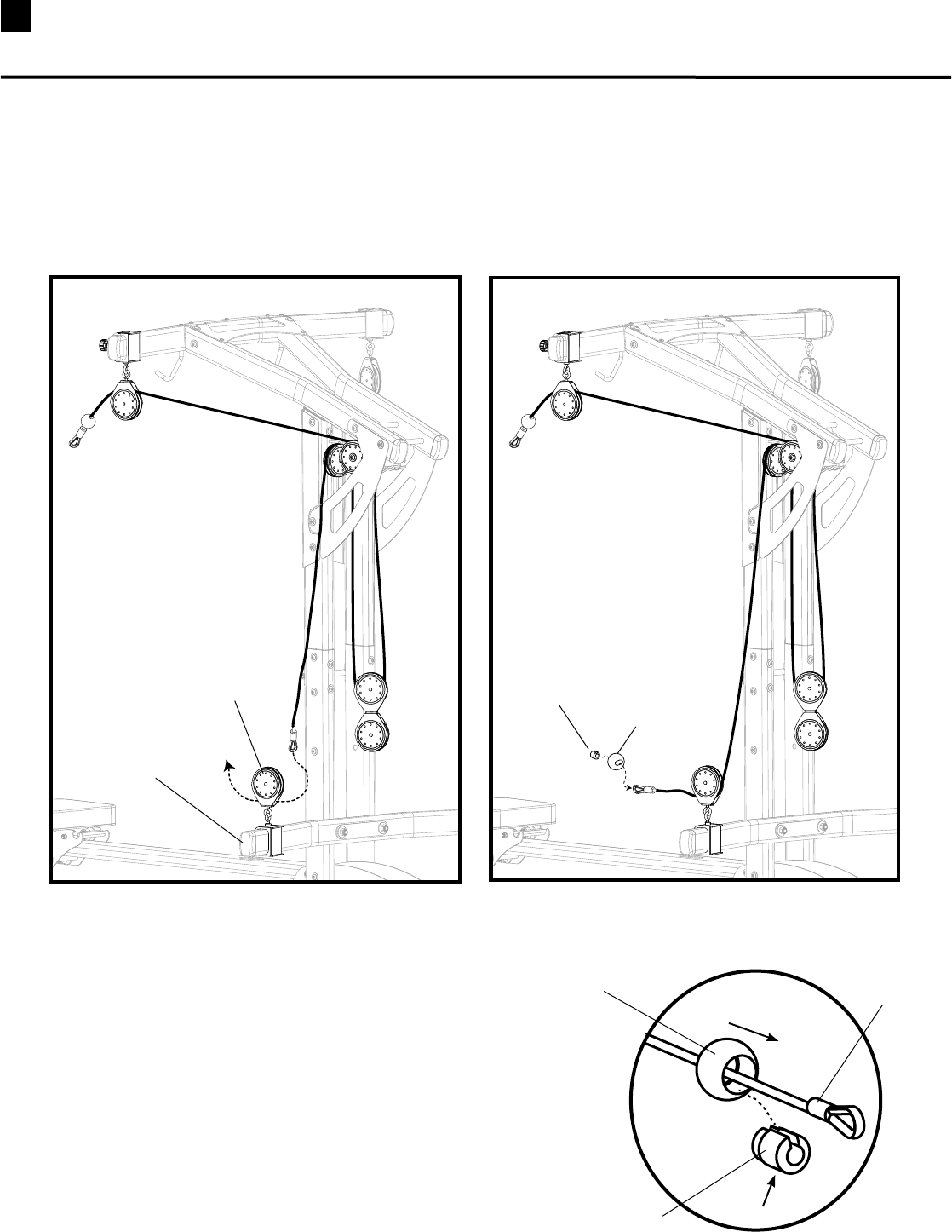
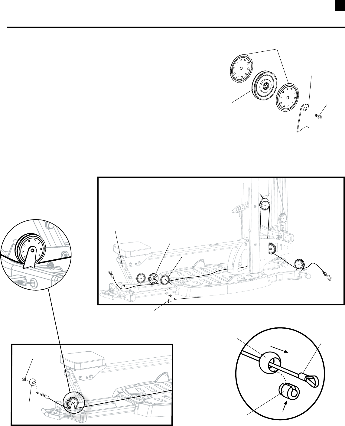
39 Installing Your Bowflex Ultimate® 2 Cables
Cable Installation STEP 5
a. ObservetheCableroutinginFigureA.
b. UnscrewtheNutandpulltheLongScrewoutjust
enoughtoanglethePulleyAssemblyandallowthe
CabletothreadbetweentheRodandthePulley.
(See Figure B)LeavetheLongScrewlooseuntilyou
haveroutedtheCableontheothersideoftheunit.
Figure A
Figure B
Floating Pulley
Long Screw
Hex Nut
Washer
Cable
Rod
Tool:
•HexKey(7/32”)
•Wrench(9/16”)- or Adjustable Wrench
Cutaway of
Rod Box
Floating Pulley
40
Cable Installation STEP 6
a. InBox3,LocateaSinglePulleyAssemblywithtwoCheeksanda
CableRetainerBracket.(See Figure A)
b. ExtendtheCabletothefrontoftheunit.
c. RoutetheCableunderthePulleyandattachthe
PulleytotheFrameinfrontoftheBenchSupport.
NOTE: Make sure the Bracket is oriented as shown. (Detail C)
d. ReplacetheBallStop.(See Figure C and D )
Tool:
•HexKey(7/32”)
Figure A
Figure B
Pulley
Cheek
Button Head Screw
Bench Support
Figure C
Slide Ball Tightly Against
Insert and Cable End
Replace Slotted Insert
Cable End
Figure D
Ball Stop
Slotted Insert
Cheeks
Pulley
REPEAT CABLE INSTALLATION STEPS 1-6 FOR THE CABLES ON THE OPPOSITE SIDE OF THE UNIT.
Installing Your Bowflex Ultimate® 2 Cables
Cable Retainer
Bracket
Button
Head
Screw
Cable Retainer Bracket
Detail C
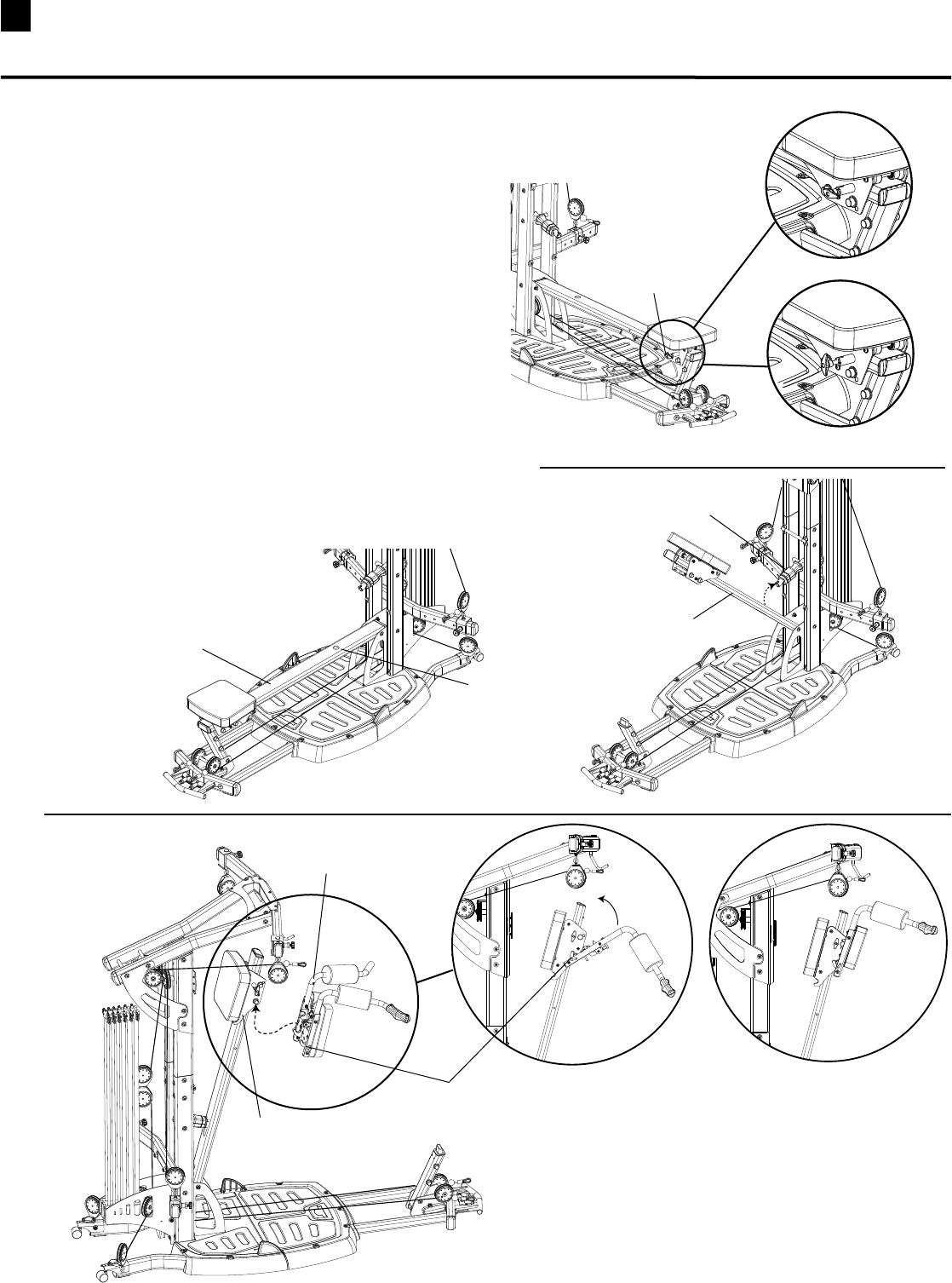
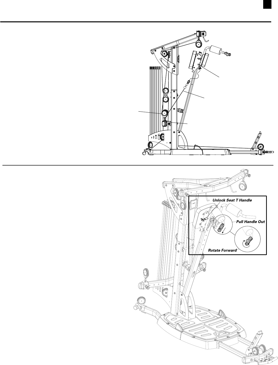
41 Installing Your Bowflex Ultimate® 2 Squat Attachment
Install Squat Attachment
1. MakesuretheSeatTHandleisLockedinpositionon
the Seat Rail. (See Figure A)
2. FoldSeatRailupandinsertSquatHolderintothe
RoundHoleontheSeatRail.MakesuretheSquat
HolderlockssecurelyintoSeatRail.(See Figure C )
3. HookthelowerHookontheSquatAttachmentup
ontothelowerPostontheSeatFrame.
4. RotateSquatAttachmentupuntilitlocksintoplace.
(See Figure D)
(Continued on page 33)
Seat Rail
Squat Holder
Seat Rail
Round Hole
Squat Attachment
Seat Frame
Lower Hook
Rotate Up Lock Into Place
Locked
Unlocked
Seat T Handle
Figure B Figure C
Figure D
Figure A
42
Operating Squat Attachment
1. UnlockSeatTHandle.(See Figure A)
2. StandunderSquatAttachmentwithShoulderPads
restingonshoulders.
3. PulltheReleaseHandleoutandrotateitforward
toallowtheSquatAttachmentslidefreelyonthe
Seat Rail. (See Figure F)
Note: The Squat Attachment will not slide
downward until you push upward to
release the safety lock.
Install Squat Attachment
(Continued from page 32)
6. ExtendtheCablefromtheChestBarSlidingPulleyto
theHooksonbothsidesoftheSquatAttachment.
(See Figure E)
Chest Bar
Sliding Pulley
Hook
Cable
Figure E
Installing Your Bowflex Ultimate® 2 Squat Attachment
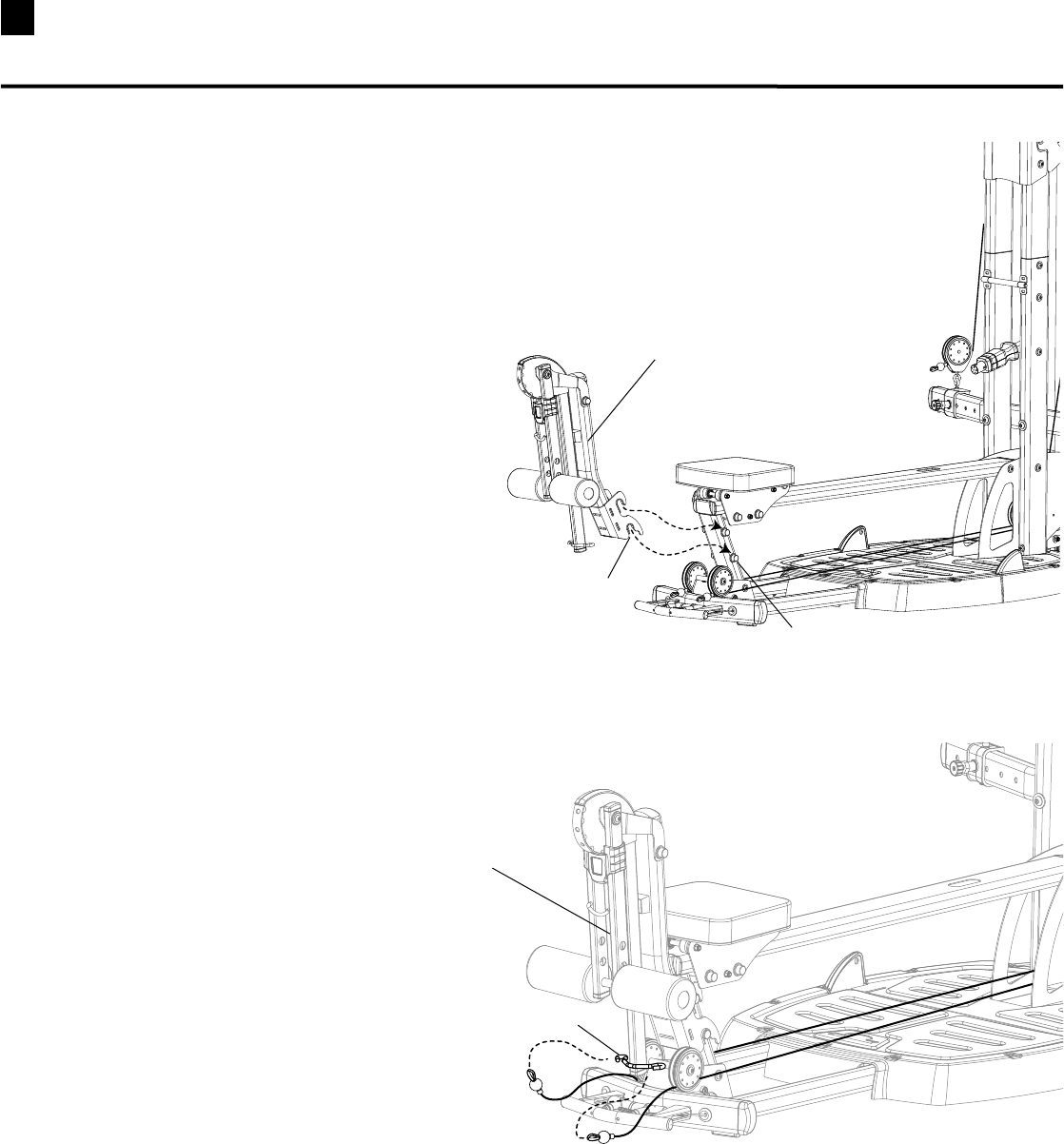
43 Installing Your Bowflex Ultimate® 2 Leg Extension Attachment
Install Leg Extension Attachment
1. PlaceHooksonLegExtensionAttachmentover
PostsonSeatRailSupportandpressdowninto
position. (See Figure A)
2. AttachCablestoCableHooksatthebottomofthe
LegExtensionAttachment.(See Figure B)
Leg Extension Attachment
Post
Hook
Cable Hook
Leg Extension Attachment
Figure B
Figure A

44
Install Leg Extension Seat
1. PlaceHooksonLegExtensionSeatFrameoverthe
postsontheLegExtensionAttachment.
2. MakesuretheCrossBarontheSeatFramerestsin
theBracketontheSlidingSeatFrame.
Leg extension Seat
Leg extension
Seat Frame
Hook
Post
Bracket
Installing Your Bowflex Ultimate® 2 Leg Extension Seat and Preacher Curl
Install Preacher Curl Attachment
1. PlaceHooksonPreacherCurlAttachmentovertheposts
ontheLegExtensionAttachment.
2. HooktheCurlBartotheWebbingattachedtotheRoller
PadBarontheLegExtensionAttachment.
Preacher Curl Attachment
Post
Hook
Curl Bar
Webbing
45
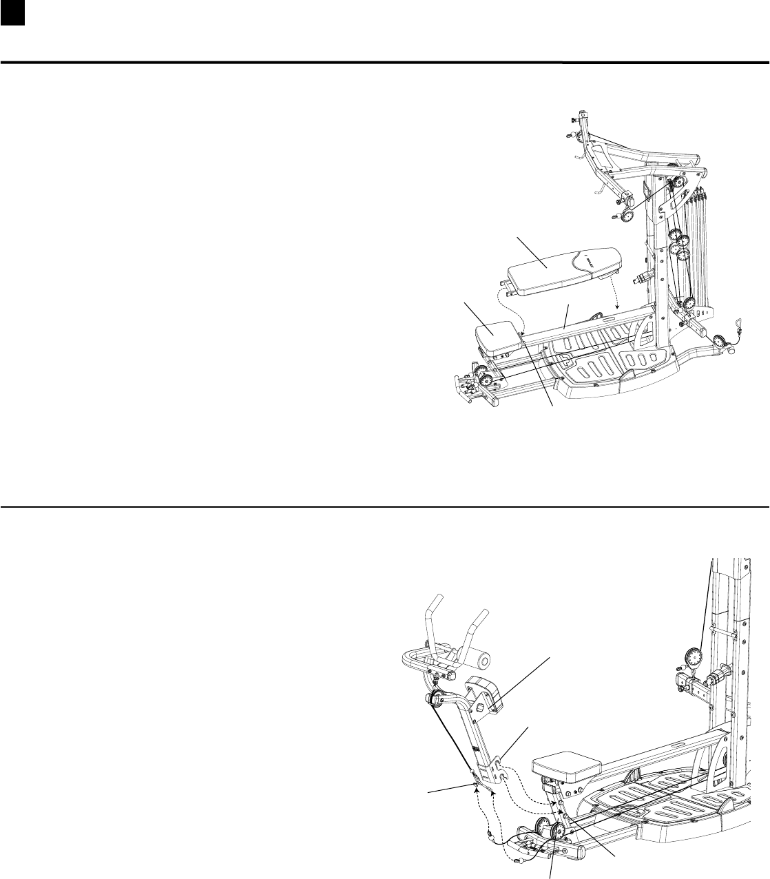
Install Ab Crunch Attachment (Optional Attachment)
1. PlaceHooksonAbCrunchAttachmentoverthe
postsontheSeatRailSupportandpressdown
into position.
2. AttachCablestoCableHooksatbottomof
AbCrunchCable.
Ab Crunch Attachment
Hook
Post
Cable Hooks
Seat Rail Support
Installing Your Bowflex Ultimate® 2 Bench and Ab Crunch Attachment
Install Bench
1. PlaceCrossBraceinBracketonSlidingSeatandlay
BenchonSeatRail.
Bench
Seat Rail
Bracket
Sliding Seat
46
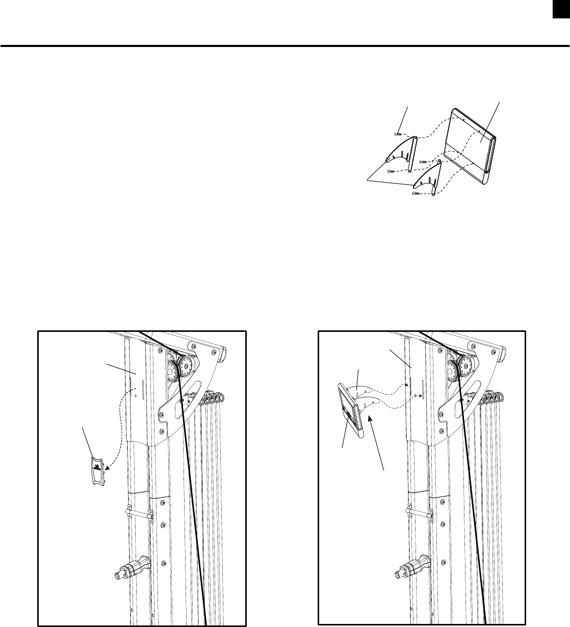
Install DVD Player (Optional Attachment)
Tool:
•SmallPhillipsHeadScrewdriver
1. AttachtheDVDPlayertothetwoDVDPlayer
BracketsusingthefoursmallPhillipsHeadScrews
providedintheBracketpackaging. (See Figure A)
2. RemovetheRubberCoverfromtheFacePlate.(See
Figure B)InserttheDVDPlayerBracketintotheslots
intheFacePlate.(See Figure C)
Note: The three slots in the DVD Bracket provide
three possible angles for viewing.
Bracket
DVD Player
Phillips Head Screw
Remove
Rubber Cover
Face Plate
Face Plate
Bracket
Use Slots
To Adjust View
Angle
DVD Player
Installing Your Bowflex Ultimate® 2 DVD Player
(Shown with optional accessories)
©2008. Nautilus, Inc. All rights reserved. Nautilus, Bowflex, the Bowflex logo, Bowflex Ultimate and Power Rod are either registered trademarks or trademarks of Nautilus, Inc.
Nautilus, Inc., World Headquarters, 16400 SE Nautilus Drive, Vancouver, WA 98683 1-800-NAUTILUS www.nautilus.com
This manual is written and designed
by industry professionals. If you
have any questions regarding
your Bowflex Ultimate® 2 or any
instructions found in this manual,
please call 1-800-605-3369 for
assistance.
