Bowflex Assembly Manual TC5500 AM
Assembly Manual TC5500_AM Bowflex Product Manuals | Bowflex
User Manual: Bowflex Assembly Manual Bowflex Product Manuals | Bowflex
Open the PDF directly: View PDF ![]() .
.
Page Count: 20
Bowflex® Bowflex®
Bowflex®T T
TreadClimber® readClimber®
readClimber®TC5500 TC5500
TC5500
001-7320–040109B

TableofContents
BeforeAssembly2Parts5
Specifications2Assembly8
ImportantSafetyInstructions3Contacts23
Tools4Instructionsdemontage25
Hardware4
BeforeAssembly
Selectwhereyouaregoingtolocateyourmachine.Thebestlocationisonahard,levelsurface.Forbestresults,assembleyour
TreadClimber®machineinthelocationwhereyouintendtouseit.Forsafeoperation,allowaworkoutareaofatleast173”x
109.5”(4.4mx2.8m)offreespace.
Followthesebasictipswhenassemblingyourmachine:
1.Readandunderstandthe“ImportantSafetyInstructions”beforeassembly.
2.Gatherallthepiecesyouneedforeachstep.
3.Useawrenchtogripthenutwhenyoutightenabolttomakesureitistight.
4.Turnallboltsandnutstotherighttotighten,andthelefttoloosen.
5.Whenattachingtwopieces,lightlyliftandlookthroughtheboltholestohelpguidetheboltthroughtheholes.
6.Assemblyrequirestwopeople.
Note:TheTreadClimber®fitnessmachineisdesignedtoplugintoagrounded,non-GFIoutletonly.Todetermineif
youroutletorcircuitbreakerisGFI,lookforatestandresetbuttononthem.Iftheyhavethetestandreset
buttonitisaGFIoutletorcircuitbreaker.
Specifications
DimensionsPowerRequirements
Length55”(139.7cm)OperationalVoltage120VAC60Hz,
Width31.5”(80cm)OperatingCurrent10Amax
Height55.25”(140.3cm)
Weight217lbs(98.5kg)
RegulatoryApprovals
c-ETL-usmark.EvaluatedperUL1647FourthEdition,January2008andCAN/CSA-C22.2.68-92.
2 2
2

ImportantSafetyInstructions
Thisiconmeansapotentiallyhazardoussituationwhich,ifnotavoided,couldresultindeathorseriousinjury.
Obeythefollowingwarnings:
Readandunderstandallwarningsonthismachine.
CarefullyreadandunderstandtheAssemblyManual.
• •
•Keepbystandersandchildrenawayfromtheproductyouareassemblingatalltimes.
• •
•Donotconnectpowersupplytothemachineuntilinstructedtodoso.
• •
•Donotassemblethismachineoutdoorsorinawetormoistlocation.
• •
•Makesureassemblyisdoneinanappropriateworkspaceawayfromfoottrafficandexposuretobystanders.
• •
•Somecomponentsofthemachinecanbeheavyorawkward.Useasecondpersonwhendoingtheassemblystepsinvolving
theseparts.Donotdostepsthatinvolveheavyliftingorawkwardmovementsonyourown.
• •
•Setupthismachineonasolid,level,horizontalsurface.
• •
•Donottrytochangethedesignorfunctionalityofthismachine.Thiscouldcompromisethesafetyandcanvoidthewarranty.
• •
•IfreplacementpartsarenecessaryuseonlygenuineNautilus®replacementpartsandhardware.Failuretousegenuine
replacementpartscancausearisktousers,keepthemachinefromoperatingcorrectlyorvoidthewarranty.
• •
•Donotuseorputthemachineintoserviceuntilthemachinehasbeenfullyassembledandinspectedforcorrectperformance
inaccordancewiththeOwner’sManual.
• •
•ReadandunderstandthecompleteOwner’sManualsuppliedwiththismachinebeforefirstuse.KeeptheOwner’sand
AssemblyManualsforfuturereference.
3 3
3
Tools
• •
•13mmOpenEndWrenchorAdjustableWrench(notincluded)
• •
•#2PhillipsHeadScrewdriver(notincluded)
• •
•UtilityKnifeorScissors(notincluded)
• •
•5mmHexWrench(included)
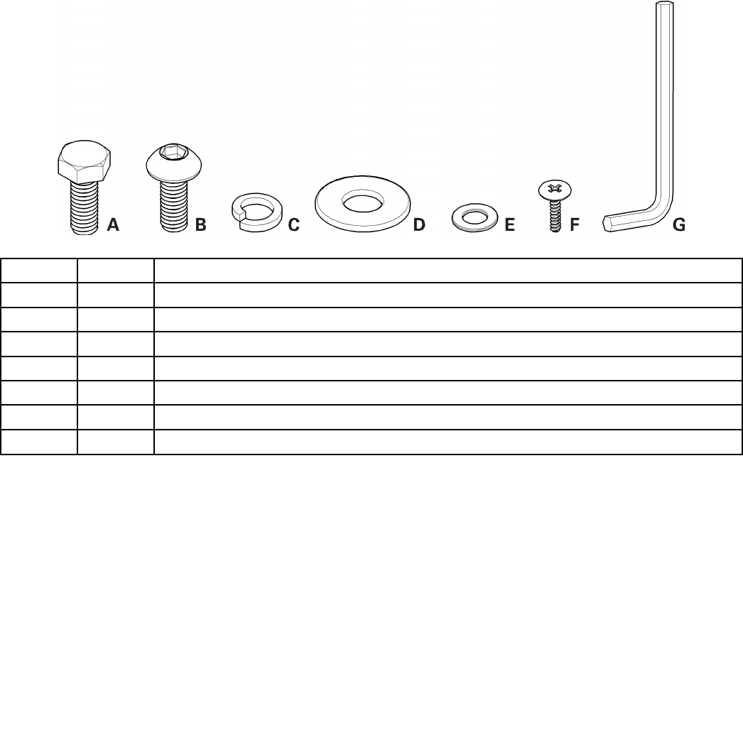
Hardware
ItemQtyDescription
A4M8x20HexHeadBolt
B16M8x20ButtonHeadHexScrew
C20M8SpringWasher
D4M8WideWasher
E16M8RegularWasher
F4SelfTappingPhillipsScrew
G15mmHexWrench
4 4
4
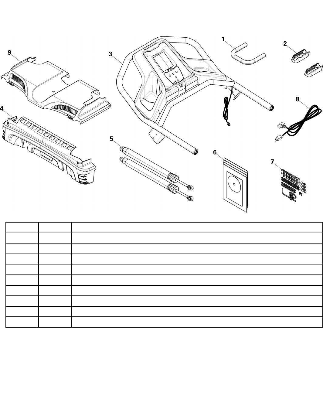
Parts
3BOXES
BOX1
ItemQtyDescription
11Handle
22JunctionCover
31Console/HandlebarAssembly
41RearCover
52Cylinder
61ManualPack
71HardwareCard
81PowerCord
91MotorCover
5 5
5
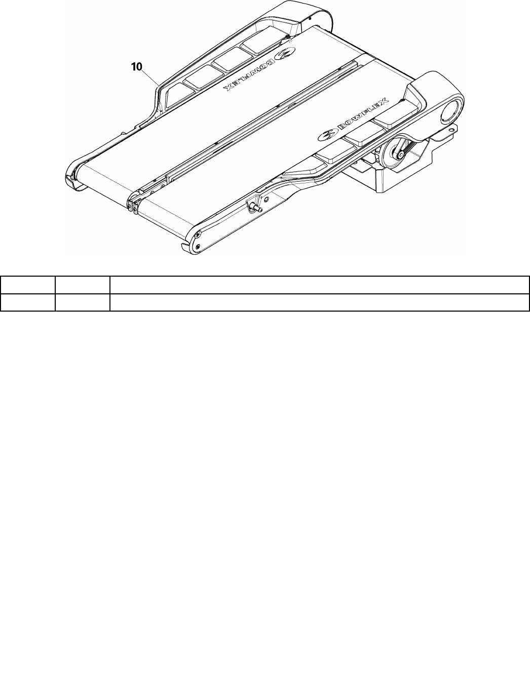
ItemQtyDescription
101TreadleAssembly
6 6
6
BOX2
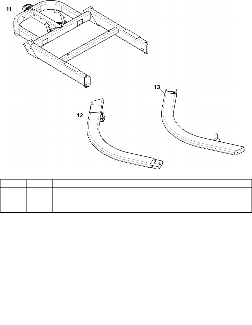
ItemQtyDescription
111Base
121Upright,Right
131Upright,Left
7 7
7
BOX3
Assembly
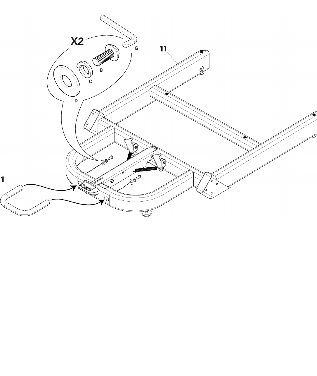
Step1:AttachHandletoBase
NOTE:Hardwareispre-installedandnotonHardwareCard.
8 8
8
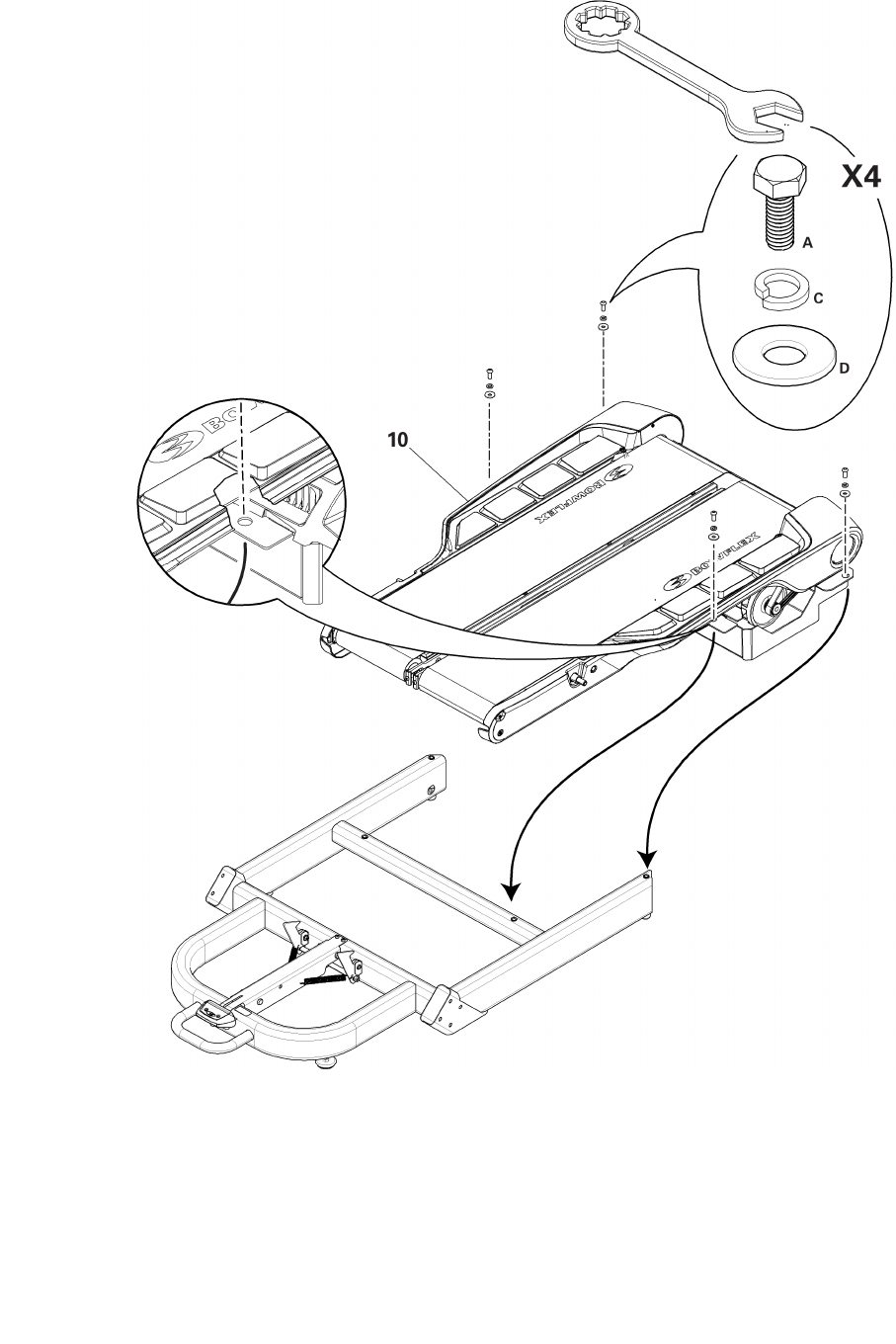
Step2:AttachTreadleAssemblytoBase
9 9
9

Step3:AttachMotorCovertoBaseAssembly
10 10
10
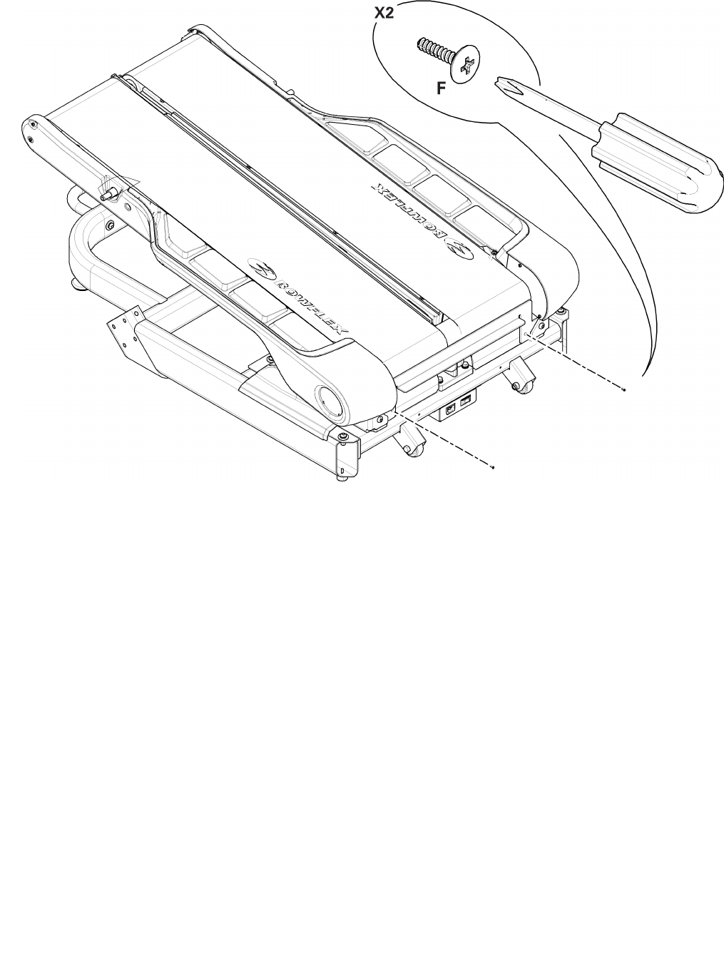
Step4:SecureMotorCovertoBaseAssembly
11 11
11
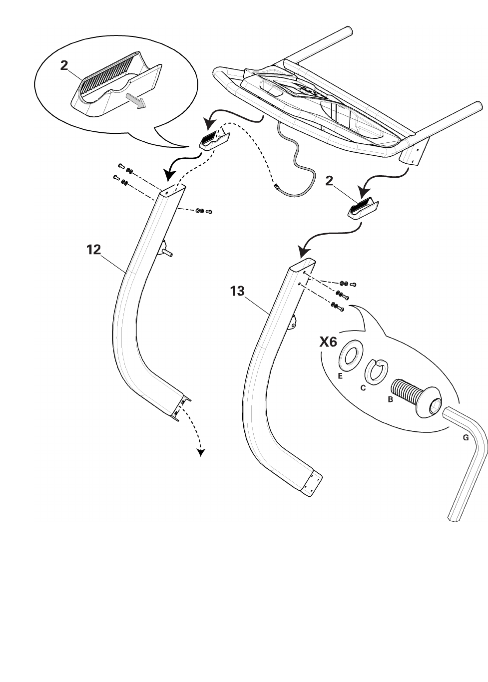
Step5:AttachJunctionCoversandUprightstotheConsole/HandlebarAssembly
NOTE:DonotcrimptheConsoleCable.
12 12
12
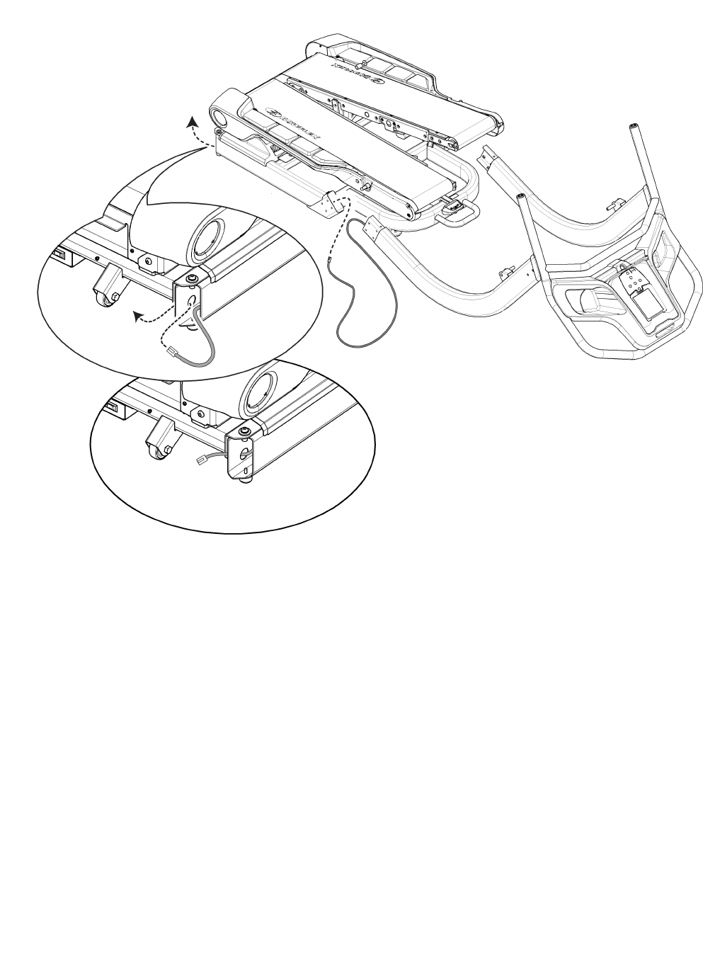
Step6:RuntheConsoleCablethroughtheBaseAssembly
13 13
13
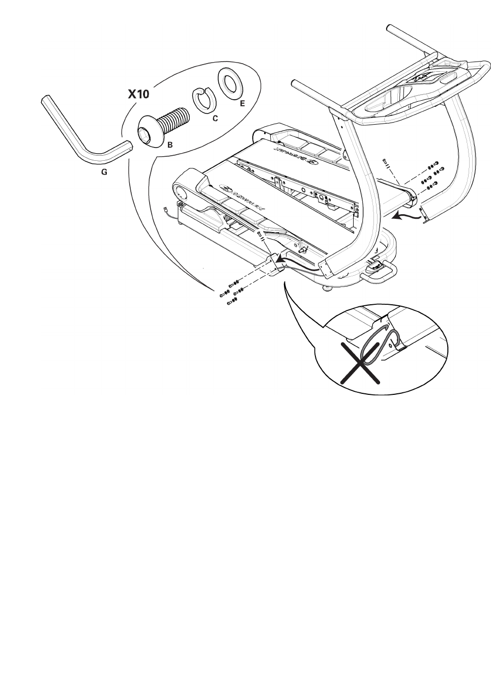
Step7:AttachtheConsole/Handlebar/UprightAssemblytoBaseAssembly
14 14
14
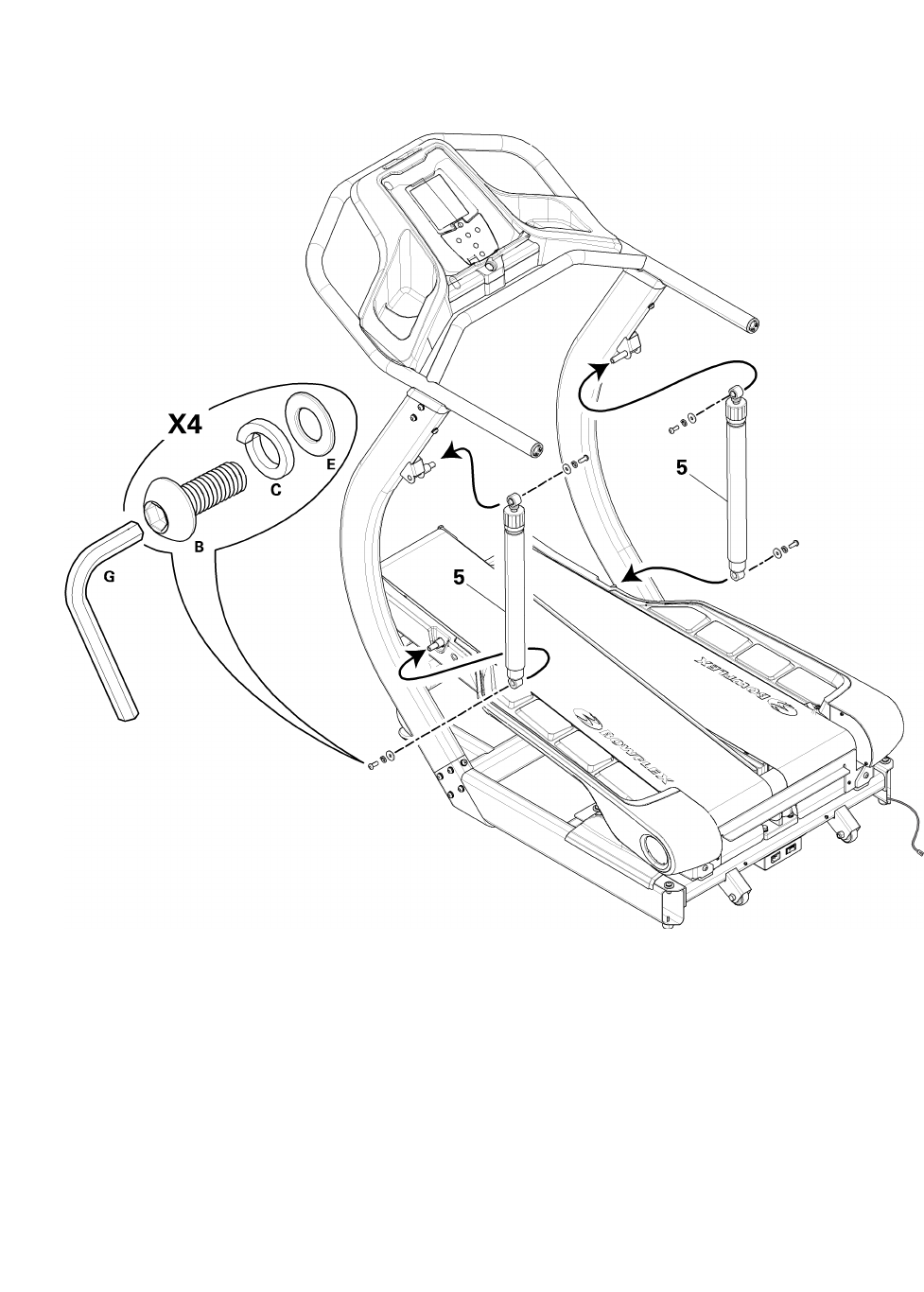
Step8:AttachCylinderstoUprightsandthenTreadle
NOTE:Hardwareispre-installedandnotonHardwareCard.
Thesingle,whitearrowontopofthecylindersmustpointupandtotherearofthemachine.Besureto
attachcylindertouprightbeforeTreadle.
15 15
15
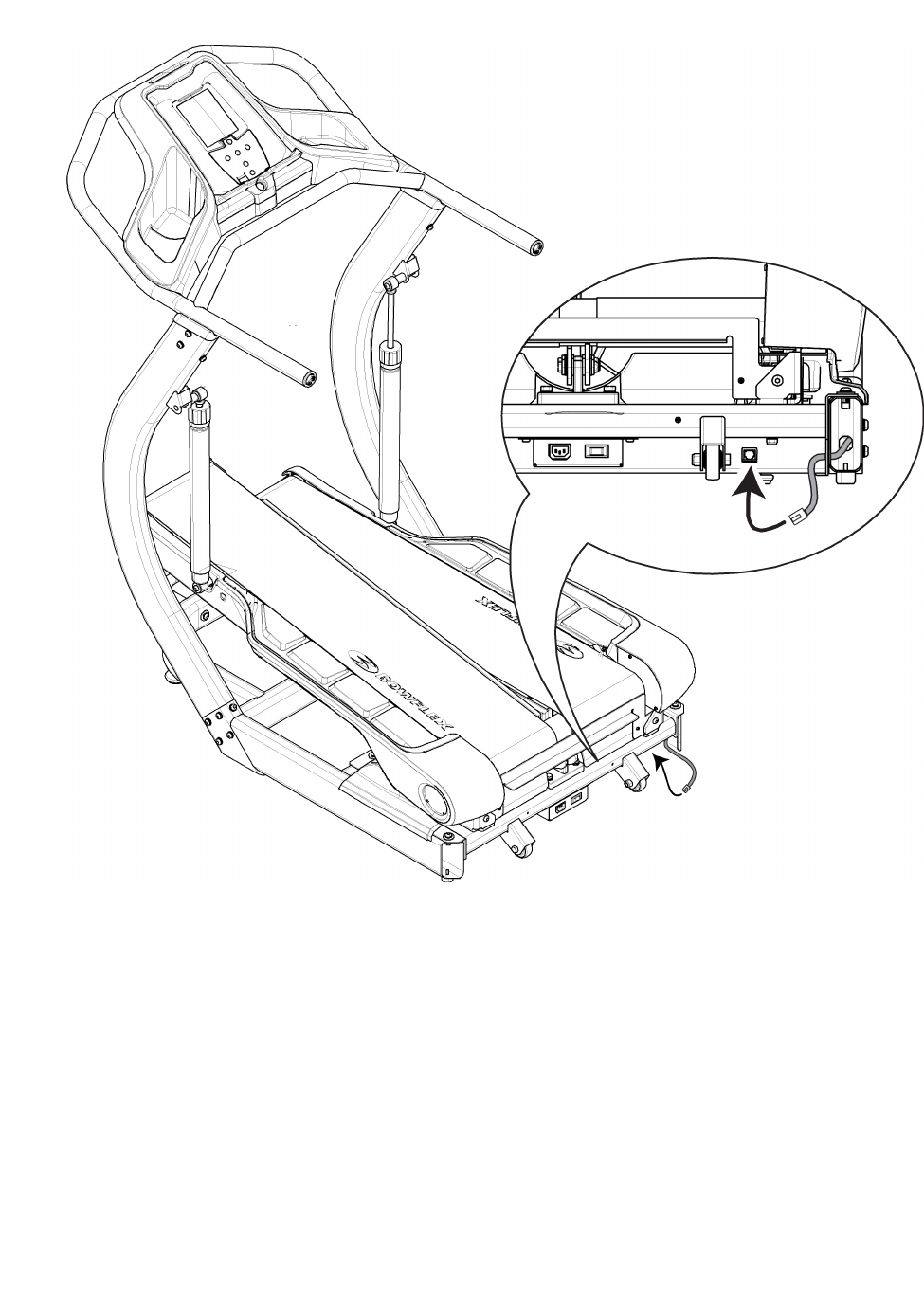
Step9:ConnecttheConsoleCabletoRearofMachine
16 16
16
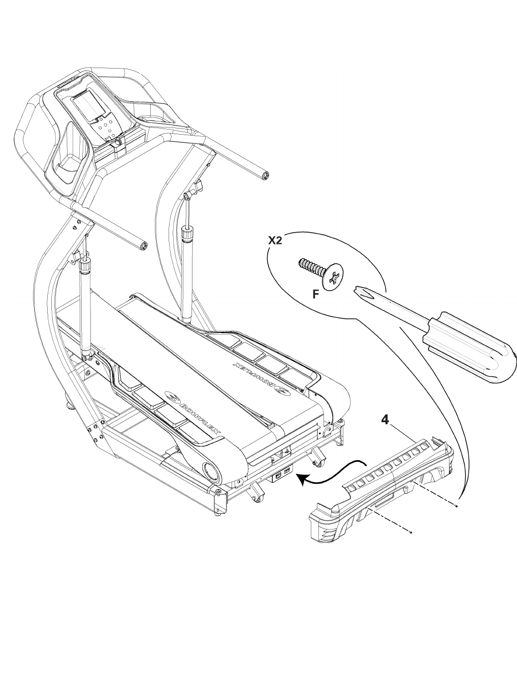
Step10:AttachRearCover
NOTE:PushtheexcessConsoleCableinsidetheframeandthenattachRearCover.
Besurethesafetytabsontheupper-insideoftheRearCoversnapontotheBaseAssembly.
17 17
17
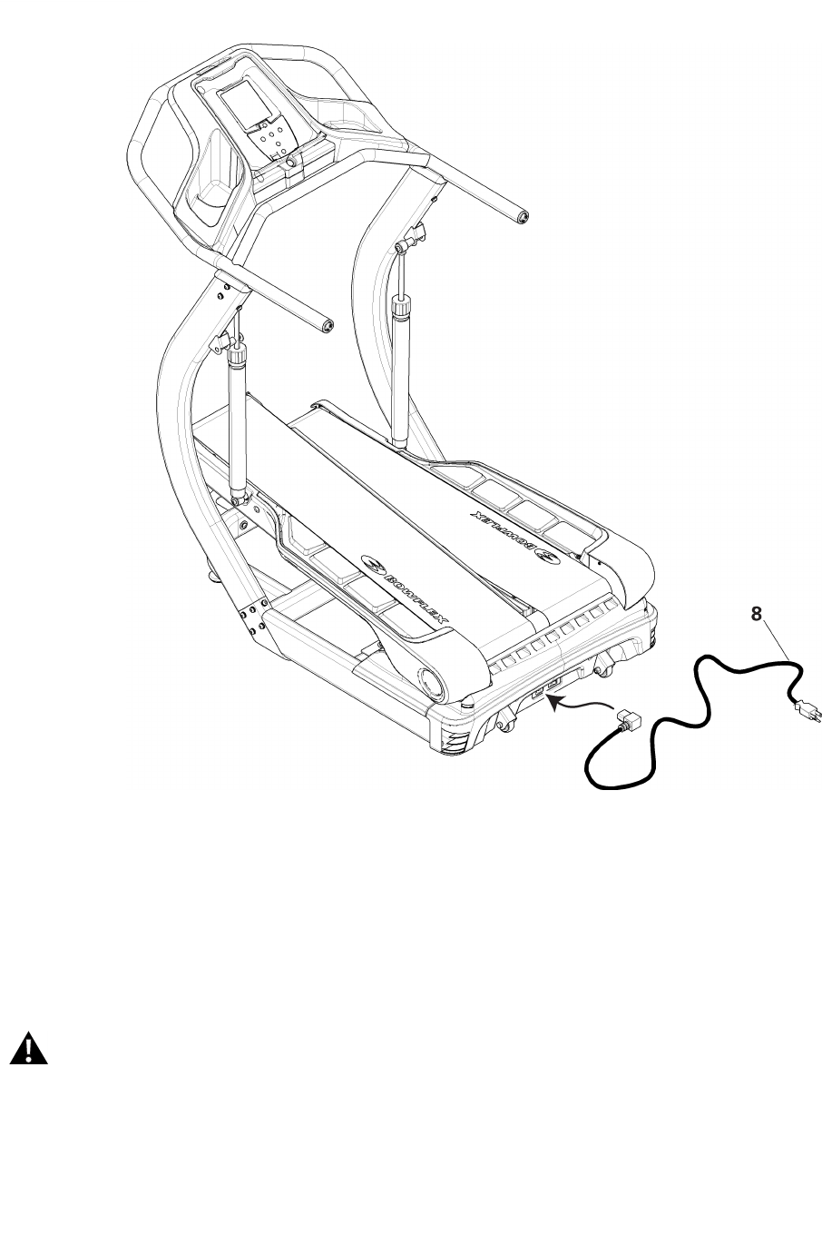
Step11:ConnectPowerCord
FinalInspection
Inspectyourmachinetoensurethatallfastenersaretightandcomponentsareproperlyassembled.
Donotuseorputthemachineintoserviceuntilthemachinehasbeenfullyassembledandinspectedforcorrect
performanceinaccordancewiththeOwner’sManual.
18 18
18

Contacts
NORTHAMERICA
CustomerService
Tel:(800)605–3369
E-mail:tcinquiries@nautilus.com
CORPORATEHEADQUARTERS
Nautilus,Inc.
WorldHeadquarters
16400SENautilusDrive
Vancouver,WA,USA98683
Tel:(800)NAUTILUS(628-8458)
ASIAPACIFIC&LATINAMERICA
CustomerService
Tel:(360)859–5180
Fax:(360)859–5197
E-mail:technics-APLA@nautilus.com
EUROPE,MIDDLEEAST&AFRICA
InternationalCustomerService
NautilusInternationalGmbH
Albin-Köbis-Str.4
51147Köln
Tel:+490220320200
Fax:+490220320204545
E-mail:technics@nautilus.com
GERMANYandAUSTRIA
NautilusInternationalGmbH
Albin-Köbis-Str.4
51147Köln
Tel:+490220320200
Fax:+490220320204545
ITALYNautilusItalyS.r.l.,ViadellaMercanzia,103
40050FunodiArgelateo-Bologna
Tel:+390516646201
Fax:+390516647461
SWITZERLAND
NautilusSwitzerlandSA
RueJeanProuvé6
CH-1762Givisiez
Tel:+41264607766
Fax:+41264607760
UNITEDKINGDOM
NautilusUKLtd
4VincentAvenue
Crownhill,MiltonKeynes,Bucks,MK80AB
Tel:+441908267345
Fax:+441908267345
19 19
19

PrintedinChina
©2009Nautilus,Inc.,Allrightsreserved
™and®indicateatrademarkorregisteredtrademark.Nautilus,Inc.(www.nautilus.com)trademarksincludeNAUTILUS®,BOWFLEX®,STAIRMASTER®,SCHWINN®andUNIVERSAL®andrespectivelogos.
Othertrademarksarethepropertyoftheirrespectiveowners.
