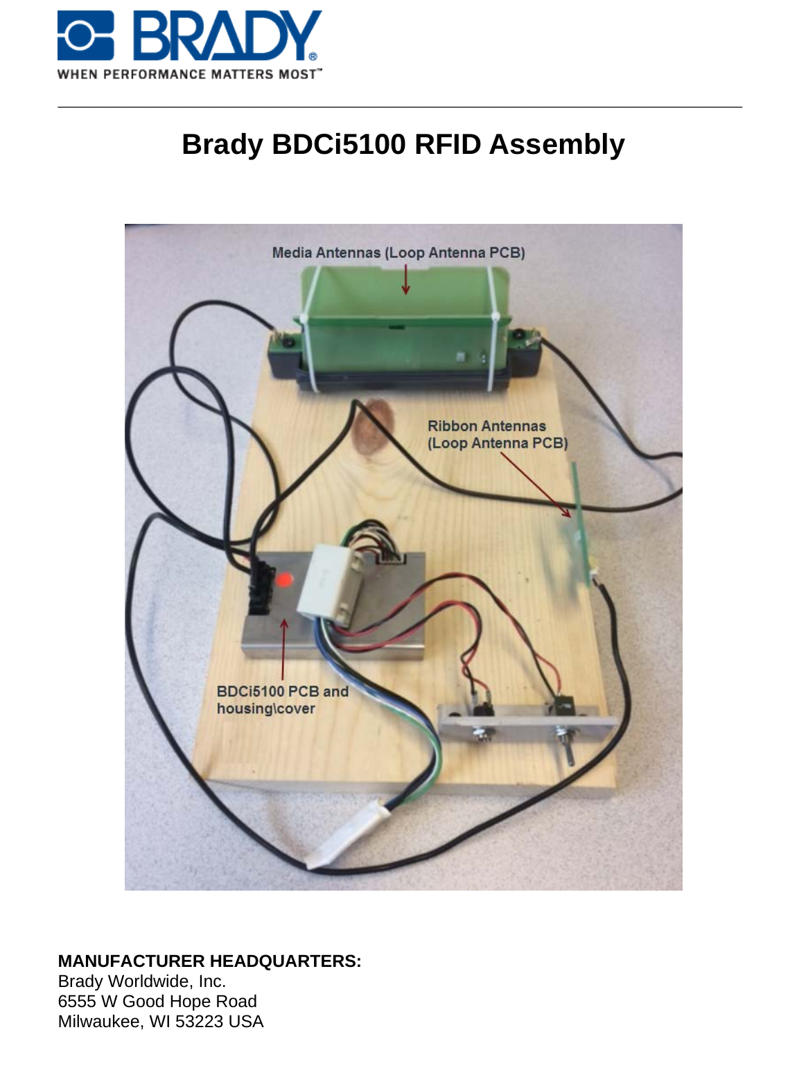
Brady BDCI5100 BDCi5100 RFID Assembly User Manual
Brady Corporation BDCi5100 RFID Assembly Users Manual
UserManual.wiki
>
Brady
>
BDCI5100 User Manual
Users Manual
Navigation menu
Upload a User Manual
Namespaces
Wiki Guide
HTML
PDF
Info
Views
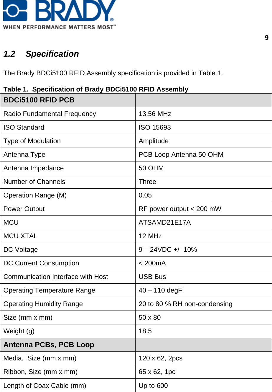
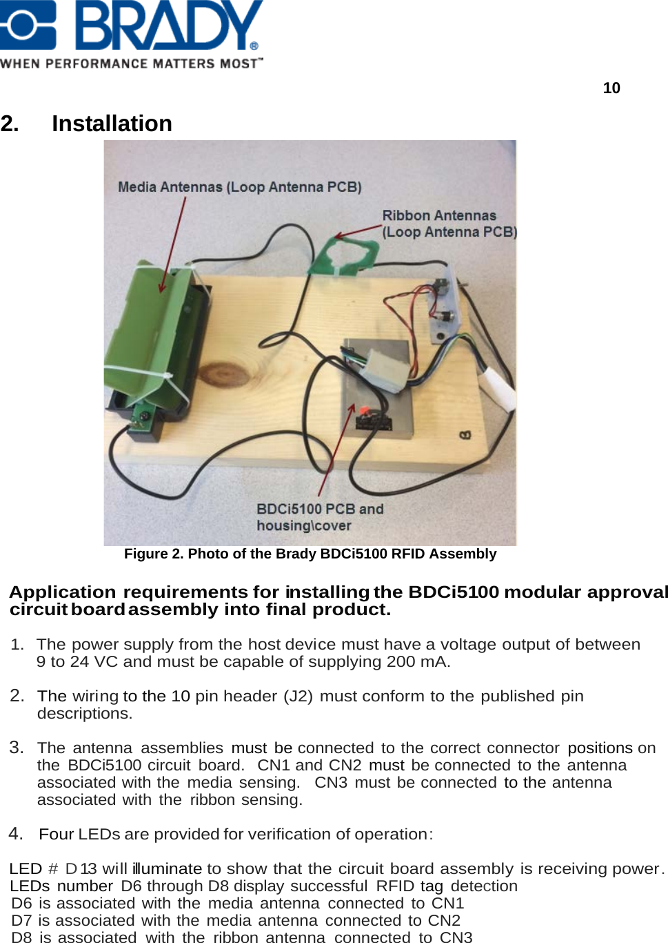
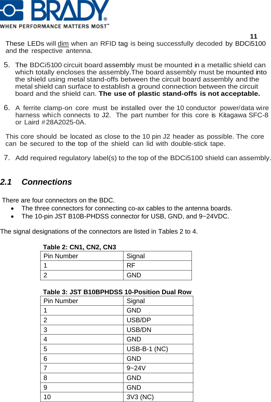
User Manual
Discussion / Help
Navigation