Braeburn Systems 7305 Electronic Programmable Thermostat User Manual part 2
Braeburn Systems LLC Electronic Programmable Thermostat part 2
Contents
- 1. User manual part 1
- 2. User manual part 2
User manual part 2
BACK NEXT
4
Operating Your Thermostat
21 User Manual
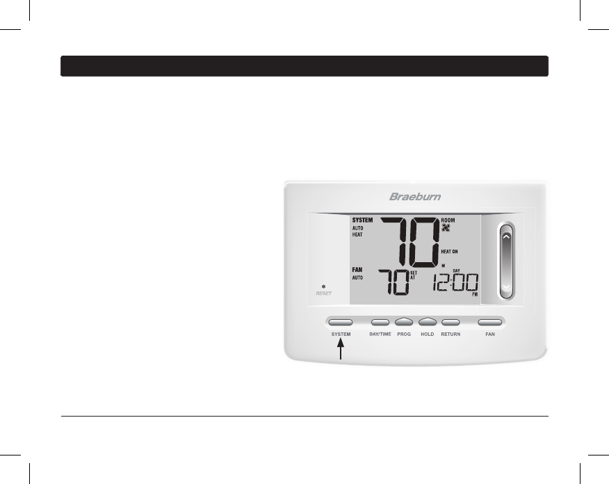
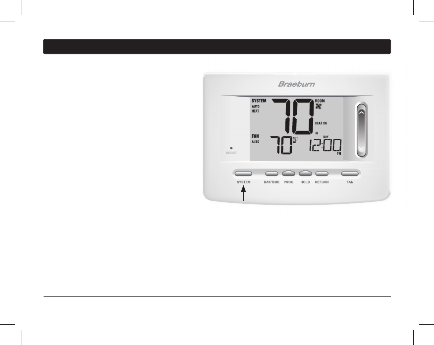
Setting the SYSTEM Control Mode
The System Control has 5 modes of operation – AUTO, COOL, OFF, HEAT and EMER. The mode can be selected
by pressing the SYSTEM button to scroll through the different modes.
NOTE: Depending on how your thermostat was configured, some system modes may not be available.
AUTO
The system will cycle between heating and
cooling automatically based on your program
set points. AUTO will be displayed with
either HEAT or COOL.
COOL Only your cooling system will operate.
OFF Heating and cooling systems are off.
HEAT Only your heating system will operate
EMER Operates a backup heat source
(Emergency Heat) for heat pump systems
only (Model 7305 only).
User Manual 22
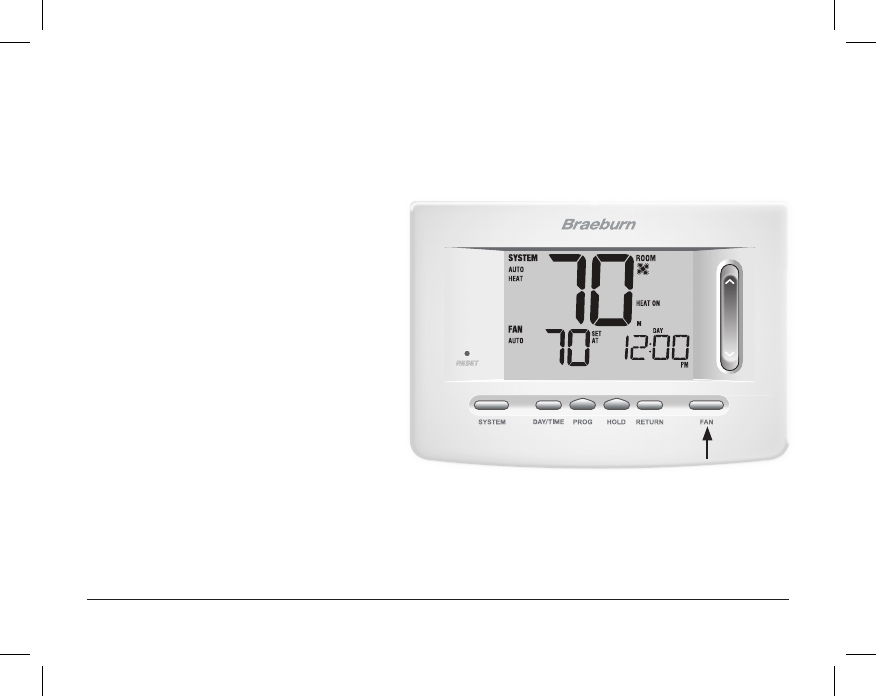
Setting the FAN Control Mode
The Fan Control has 3 modes of operation – AUTO, ON, and PROG. The mode can be selected by pressing the
FAN button to scroll through the different modes.
NOTE: Depending on how your thermostat was configured, some fan modes may not be available.
AUTO The system fan will run only when your
heating or cooling system is running.
ON The system fan stays on.
CIRC The system fan will run intermittently to
help circulate air and provide more even
temperature distribution when the
heating or cooling system is not active.
PROG The system fan will function in the
AUTO or ON modes depending on your
program schedule.
23 User Manual
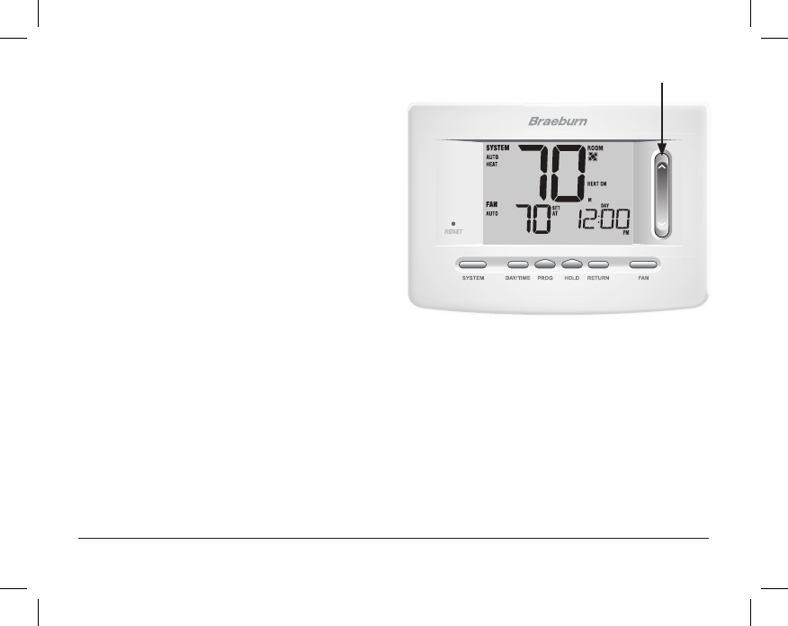
Setting the Temperature
Temporary Adjustment –
Press the SpeedBar® up or
down
to adjust the current set temperature. If your
thermostat is running in 5-2 or 7 day programmable
mode, the set temperature will change back to your
original programmed settings when your next scheduled
change in temperature occurs.
Extended Adjustment – Press the HOLD button
so that HOLD appears in the display screen. Press the
SpeedBar up or down to adjust the current set temperature
(See Extended Hold Period, page 10).
NOTE: If this thermostat was configured to be non-
programmable, you will not have a HOLD option.
SpeedBar
User Manual 24
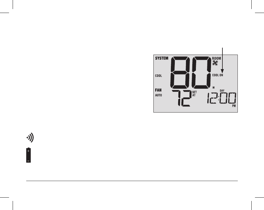
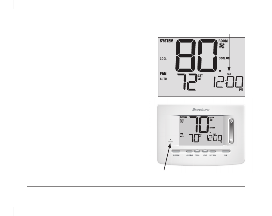
Status
Indicator
Status Indicators
Status indicators appear in the display to let you know if your system is heating, cooling or off.
HEAT ON Heating system is running.
COOL ON Cooling system is running.
AUX Auxiliary stage of heating is running (multi-stage
systems only).
EMER
Emergency heating system is running
(model 7305 heat pump systems only).
CHECK There is a potential problem with your system.
Contact a local service technician (model 7305 only).
SERVICE User selectable service reminder for changing a lter,
UV air purier bulb or humidier pad (see Service
Monitors, page 10).
ADJ Temperature adjustment limit has been reached.
Thermostat is connected to Wi-Fi network (ashes if connection is lost).
Thermostat battery is low (see Thermostat Maintenance, page 31).
NO POWR AC Power to system has been lost (see page 29).
25 User Manual
Reset
Button
Program Event Indicators
Program event indicators appear in the display to let you
know what part of your current program is active.
• In Residential Program Mode, MORN, DAY, EVE or NIGHT
will appear.
•
In Commercial Program Mode, OCCUPIED or UNOCCUPIED
will appear.
When the program event indicator is ashing, your program
has been temporarily bypassed and will resume at the
next scheduled event.
NOTE: You will not see a program event indicator while in
HOLD or Non-Programmable Mode.
Resetting the Thermostat
This thermostat provides you with a reset button that will
erase all of your user settings and programming.
The reset feature does not affect the Installer Settings.
To reset the thermostat, use a small object such as a
tooth pick or paperclip and gently press the button located
inside the small hole on the front of the thermostat housing
labeled “RESET ”.
NOTE: You cannot reset the thermostat if it is locked.
Program Event
Indicator
5
Additional Operation Features
Auto Changeover Mode
Auto Changeover mode is a feature enabled/
disabled in the
Installer Settings (see Installer
Manual). If enabled, it is selected
by pressing the
SYSTEM button until AUTO HEAT or AUTO COOL
appears in the display.
When Auto Changeover mode is enabled and
selected, the system automatically switches
between heating and cooling when the room
temperature meets the programmed heating or
cooling set points. To operate properly, the
thermostat requires a “dead band” setting to
eliminate program conicts. The dead band is set
in the Installer Settings (See Installer Guide). The
default setting is 3° F. Therefore, you will not be able
to set your heat or cool temperature within 3° F of each other. If a setting is made in either heating or cooling
which violates the dead band, the opposite mode will adjust up or down automatically to maintain the pro-
grammed dead band spacing.
User Manual 26
27 User Manual
Adaptive Recovery Mode (ARM
™
)
Adaptive Recovery Mode is a feature enabled/disabled in the Installer Settings (See Installer Guide).
If enabled, the feature is automatically present while in programmable mode.
Adaptive Recovery Mode tries to reach your desired heating or cooling temperature at the time you have set in
your current program schedule, after a setback period. For example, if you set your heat down to 62° at night
and have a set point of 70° scheduled for 7:00 AM, the thermostat may turn on your heating system early in
order achieve a temperature of 70° by 7:00 AM.
This feature does not operate when the thermostat is in HOLD mode, if the program is temporarily overridden or
if emergency heat is selected on a multistage heat pump system.
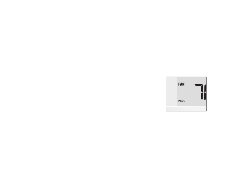
Programmable Fan Mode
Programmable Fan Mode is selected by pressing FAN until PROG appears in the
display. It is only available in 7 or 5-2 Day programmable mode.
Programmable Fan Mode allows the user to run the fan continuously during a selected
program event. To use this feature, select fan ON while setting program events.
(See “Setting Your Program Schedule”, page 13).
DAY/ TIME
DAY/TIME
BACK NEXT
User Manual 28
Compressor Protection
Compressor protection is enabled/disabled in the Installer Settings (See Installer Guide). If enabled, this
feature is automatically present in cooling and/or heating modes. This thermostat includes an automatic
compressor protection delay to avoid potential damage to your system from short cycling. This feature activates
a short delay after turning off the system compressor. Additionally, for multi-stage heat pump systems, this
thermostat provides cold weather compressor protection by locking out the compressor stage(s) of heating for
a period of time after a power outage greater than 60 minutes. This cold weather compressor protection can be
manually overridden at any time by changing the system mode to OFF momentarily, then back to HEAT.
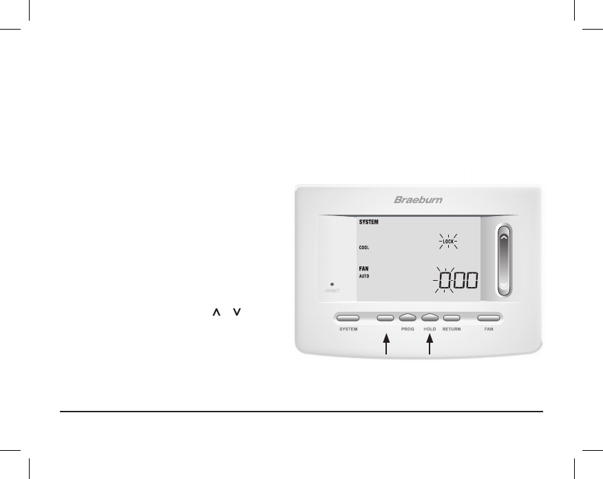
Locking and Unlocking the Thermostat
Your 3-digit Lock Code is set in the “User Options”
portion of this manual (See “Setting User Options”,
page 8, 9 and 11).
Once the code is set, the
thermostat can be locked or unlocked at any
time by entering that code.
To lock or unlock the thermostat, press and hold the
DAY/TIME and HOLD buttons together for 5 seconds.
The screen will change, displaying 000 and LOCK
will be ashing. Press the SpeedBar® or to
enter
the rst digit of your lock code and then press
NEXT* to advance to the next digit. Repeat this
process to enter the second and third digit of your
lock code. After entering the third digit, press RETURN.
*BACK and NEXT are secondary functions of the PROG and HOLD buttons.
DAY/TIME
BACK NEXT
29 User Manual
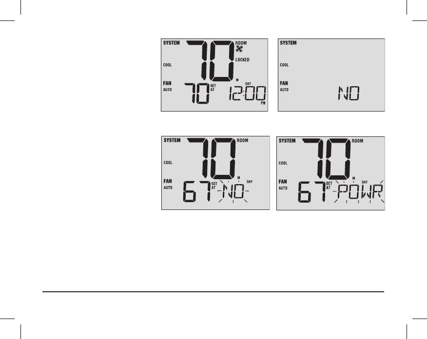
If you entered a valid code the
thermostat will be locked or unlocked
(depending on its previous state).
When locked, the word LOCKED
appears in the display (Figure 1). If an
invalid code is entered the word
NO
will briey appear, indicating that an
incorrect code was entered (Figure 2).
Figure 1 Figure 2
AC Power Monitor
The AC Power Monitor feature is
enabled in the Installer Settings
(See Installer Guide). If enabled,
this feature will automatically
be present. If your thermostat was
hardwired (power provided from the
system with batteries as a backup)
then the AC Power Monitor feature
will indicate when a loss of power to the
thermostat has occurred by ashing NO POWR.

User Manual 30
Indoor Remote Sensing
Indoor remote sensing is achieved by installing a Braeburn
®
remote indoor sensor and is configured in the
Installer Settings (See Installer Guide).
If a Braeburn indoor remote sensor was installed and properly congured in the Installer Settings, the thermostat
will sense temperature at a remote location or a combination of a remote location and the thermostat location.
DAY/TIME
Outdoor Remote Sensing
Outdoor remote sensing is enabled by installing
a Braeburn
®
remote outdoor sensor. No additional configuration is required.
If a Braeburn outdoor remote sensor was installed you may
press the PROG and HOLD buttons at the same time to
view the outdoor temperature.
FCC Statement
This equipment has been tested and found to comply with the limits for a Class B
digital device, pursuant to Part 15 of the FCC Rules. These limits are designed to
provide reasonable protection against harmful interference in a residential
installation. This equipment generates uses and can radiate radio frequency energy
and, if not installed and used in accordance with the instructions, may cause harmful interference to radio communications. However, there is no
guarantee that interference will not occur in a particular installation. If this equipment does cause harmful interference to radio or television reception,
which can be determined by turning the equipment off and on, the user is encouraged to try to correct the interference by one or more of the following
measures:
-- Reorient or relocate the receiving antenna.
-- Increase the separation between the equipment and receiver.
-- Connect the equipment into an outlet on a circuit different from that to which the receiver is connected.
-- Consult the dealer or an experienced radio/TV technician for help.
Changes or modifications not expressly approved by the party responsible for compliance could void the user's authority to operate the equipment.
The distance between user and products should be no less than 20cm
31 User Manual
6
Thermostat Maintenance
Thermostat Cleaning
Never spray any liquid directly on the thermostat. Using a soft damp cloth wipe the outer body of the thermostat.
Never use any abrasive cleansers to clean your thermostat.
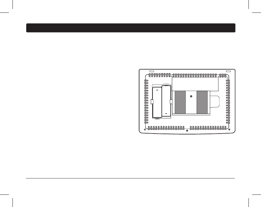
Changing the Batteries
This thermostat requires two (2) properly installed “AA”
alkaline batteries to maintain the thermostat clock and to
provide power for the thermostat if 24 volt AC power is not
connected. (See Installer Guide).
If batteries become low, a battery indicator will appear
in the display. You should change your batteries immediately
when you see the low battery signal by following
these instructions.
1. Remove thermostat body by gently pulling it from base.
2. Remove old batteries and replace with new batteries.
3. Make sure to correctly position the (+) and (-) symbols.
4. Gently push thermostat body back onto base.
NOTE: We recommend replacing the thermostat batteries annually or if the thermostat will be unattended for
an extended period of time.
+
+
®
Braeburn Systems LLC
2215 Cornell Avenue • Montgomery, IL 60538
Technical Assistance: www.braeburnonline.com
Call us toll-free: 866-268-5599 (U.S.)
630-844-1968 (Outside the U.S.)
©2016 Braeburn Systems LLC • All Rights Reserved • Made in China. 7300-110-01
®
Limited Warranty
When installed by a professional contractor, this product is backed by a 5 year limited
warranty. Limitations apply. For limitations, terms and conditions, you may obtain a full
copy of this warranty:
· Visit us online: www.braeburnonline.com/warranty
· Phone us: 866.268.5599
· Write us: Braeburn Systems LLC
2215 Cornell Avenue
Montgomery, IL 60538
5
YEAR
WARRANT Y
LIMITED
Store this manual for future reference.
For additional information visit: www.braeburnonline.com
For online access visit: www.bluelinksmartconnect.com