Braun Corporation Fmvss No 403 Users Manual
403 to the manual 3062a17b-8e38-4db5-93d0-dca872d9d80e
2015-02-02
: Braun Braun-Corporation-Fmvss-No-403-403-Users-Manual-409694 braun-corporation-fmvss-no-403-403-users-manual-409694 braun pdf
Open the PDF directly: View PDF ![]() .
.
Page Count: 8
Braun Corporation FMVSS No. 403 Quick Reference Installation Sheet 31312
e
g
d
e
W
e
t
a
l
P
e
g
d
e
W
e
t
a
l
P
e
m
ar
F
e
b
u
T
Ground Level
Vehicle
Door
Opening
Door Opening Dimensions
Vehicle lift access door opening
must meet specified dimensions.
OEM (Van) Chassis Floor Requirements
Nonmodified OEM full size van floors meet
all requirements for Vangater II. Nonmodi-
fied OEM mini van floors meet all require-
ments for Mini Vangater II.
h$/40RIVATE5SE,IFTv
.(43!6EHICLE0HYSICAL2EQUIREMENTS
Lowered (Drop) Floor Requirements
Must meet or exceed nonmodified
OEM floor section.
&IGURE!
&IGURE"
"RAUN#ORPORATION&-633.O
1UICK2EFERENCE)NSTALLATION3HEET
Clear Door Opening
Minimum Clear
Dimen- Minivan Full Size
Maximum Floor-to-
A
B
C
A
B
C
39-1/2"
48"
29"
“1992” and Newer Ford Slide Door
1. Remove the lower slide door stop.
2. With Power Door: Door stop not
used.
Without Power Door: Drill (2) holes
in the lower door stop at dimensions
shown in Figure B.
3. Replace door stop, locating on the
(2) drilled holes (provides adequate
clearance).
2-3/4"1-7/16"
Drill (2) 5/16" diameter holes.
r
o
o
D
g
n
i
w
S
r
a
e
R
r
o
o
D
g
n
i
w
S
t
n
o
r
F
Wall
Floor
Wall
(ALIGNED) PARALLEL (ALIGNED)
Wall
(ALIGNED) PARALLEL (ALIGNED)
Slide Door
Floor
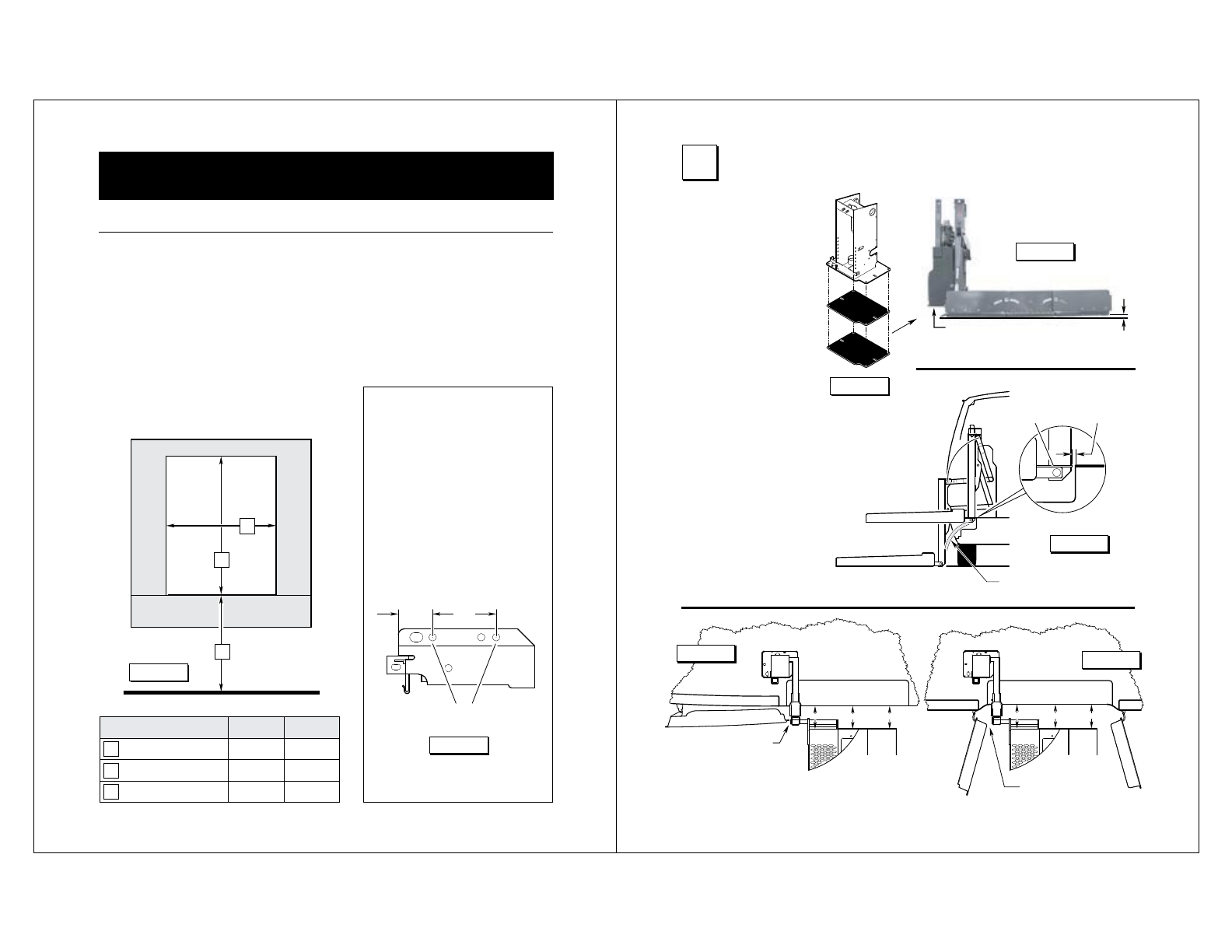
Place lift in approximate
position. Note: Hoist
or other lifting device is
recommended.
Position wedge plate(s)
to achieve a 1/2" pre-
load at right inboard
corner of platform. See
Figures C and D.
Clearances
Minimum 1" clearance
between lift and vehicle.
See Figure E.
Maximum 1/2" between
inboard locator and floor
when locator is deployed.
See Figure E.
Minimum 3/4" clearance
between door and verti-
cal arm. See Figures F
and G.
Minimum 3/4"
Clearance
&IGURE'
Minimum 3/4"
Clearance
Position wedges as
needed for 1/2" preload.
&IGURE$
1/2"
Stepwell
Floor
Inboard
Locator
Maximum
1/2"
Minimum 1" Clearance
&IGURE%
&IGURE&
&IGURE#
10OSITION,IFT
31-1/2"
42"
29"
Braun Corporation FMVSS No. 403 Quick Reference Installation Sheet 31312
e
c
a
r
B
g
n
i
t
n
u
o
M
l
a
c
i
t
r
e
V
e
m
a
r
F
e
b
u
T
23ECURE,IFT
e
g
d
e
W
e
t
a
l
P
e
g
d
e
W
e
t
a
l
P
r
o
o
l
F
e
m
a
r
F
e
b
u
T
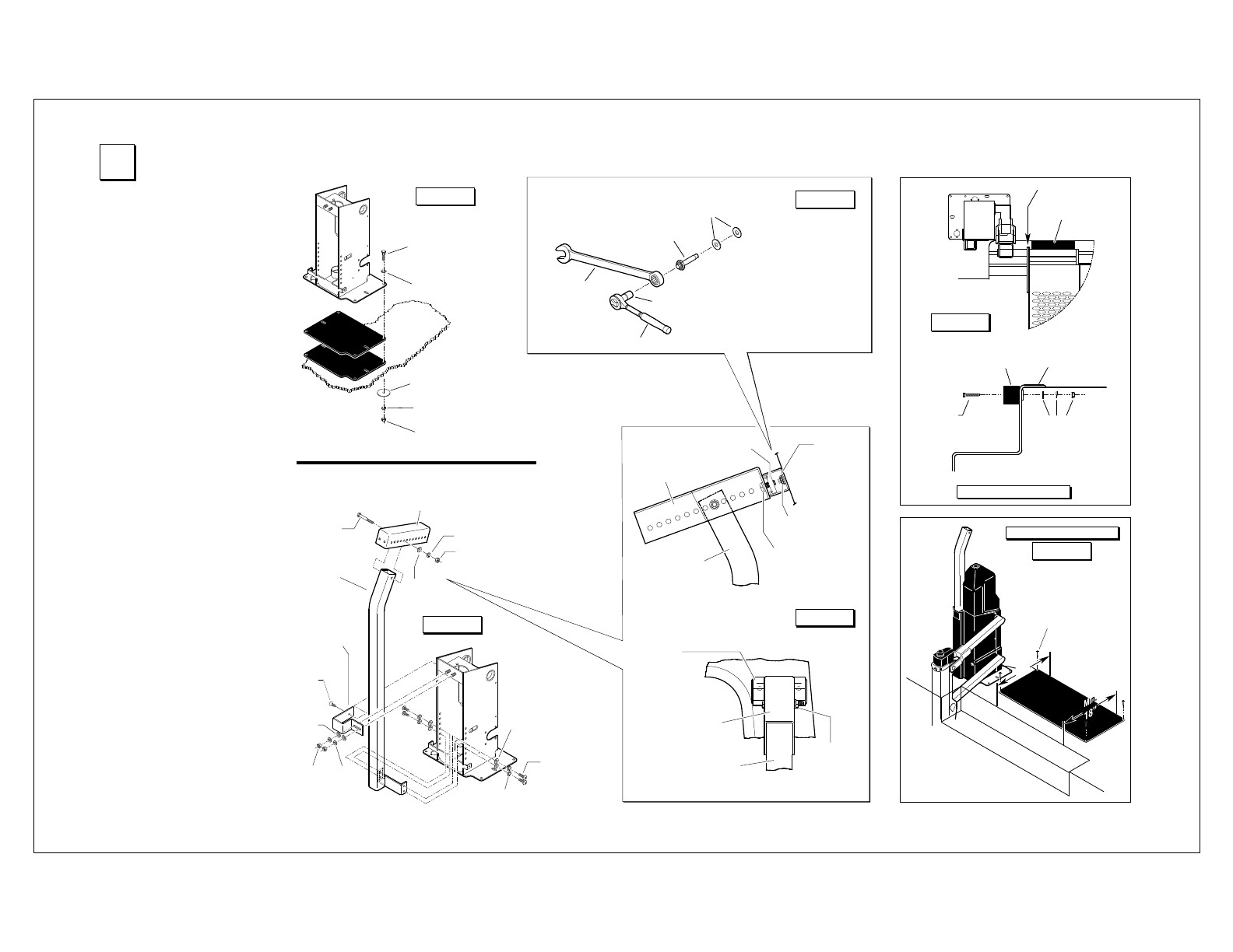
3/8-16 Hex Bolt
(Minimum 4)
• One in each corner.
• Lengths as required
per application.
5/16" Flat Washer
3/8" Body Washer
3/8" Lock Washer
3/8-16 Hex Nut
Hardware
Typical
All Positions
Position
wedges
as needed.
&IGURE(
Docking
Bumper
Outer Pivot
Platform
Docking
Bumper
Stepwell
Floor
Trim
5/16" Flat Washer
3/8" Lock Washer
3/8-16 Hex Nut
3/8-16 x 2"
Hex Bolt
(Qty: 2)
Docking Bumper
r
o
o
l
F
d
e
h
s
i
n
i
F
f
o
e
g
d
E
d
l
o
h
s
e
r
h
T
g
n
i
n
r
a
W
.
n
i
M
"
8
1
#10-16 x 1-1/2"
Wafer Head Phillips
Self-Drilling Screw
(Qty: 4)
Threshold Warning
Upper
Adjustment
Bracket
Upper
Mounting
Channel
3/8-16 x 1"
Hex Cap Screw
with
Lock Washer
(Qty: 2)
3/8-16 Slide Nut
Vertical
Mounting
Brace
Fab-Lock Bolt
Upper
Mounting
Channel
Upper
Adjustment
Bracket
Vertical
Mounting
Brace
3/8-16 x 3"
Hex Bolt
with
Lock Washer
and Hex Nut
Wall (C Pillar)
5/16-18 x 7/8"
Button Head
Cap Screw
Upper
Mounting
Bracket
5/16"
Hex
Nut
5/16-18 x 3/4"
Flat Head
Screw
3/8-16 x 3"
Hex Bolt
Upper
Adjustment
Bracket
3/8" Lock
Washer
3/8" Hex
Nut
5/16" Flat
Washer
5/16"
Lock
Washer
&IGURE)
5/16" Flat
Washer
5/16"
Flat
Washer
5/16" Lock
Washer
Vertical
Mounting
Brace
Fab-Lock Bolt
1/4" Flat Washers
Ratchet Wrench
5/16" Socket
5/8" Wrench
1. Remove rubber
washer and install
1/4" flat washers.
3. Place a 5/8"
wrench onto
bolt head and
secure tightly
4. Place a 5/16" socket onto the inner
screw and tighten (turn clockwise).
5. Turn socket until Fab-Lock has
expanded against metal surface.
Fab-Lock Bolt Installation &IGURE*
&IGURE+
&IGURE-
&IGURE,
2. Insert Fab-Lock bolts (minimum
2) fully through mounting channel
and C pillar.
Note: Cut bracket off flush with
mounting brace and install foam
padded cover using cable ties.
1. Temporarily secure base plate by
installing sheet metal screws in
base plate slots.
2. Secure vertical mounting brace
and upper mounting bracket to
frame tube. See Figure I.
3. Temporarily assemble upper ad-
justment bracket and upper mount-
ing channel. See Figure K. Posi-
tion assembly and mark mounting
holes on van wall (C pillar).
Carefully drill 5/16" diameter wall
mounting holes. Secure upper
mounting channel to wall (C pillar)
using expanding Fab-Lock bolts
(minimum 2). See Figure J.
4. Secure upper adjustment bracket
and upper mounting channel as-
sembly to vertical mounting brace.
5. Carefully operate lift through all
functions checking for clearances
(specified in Figures D-I). Adjust
lift position and/or upper mounting
hardware as needed.
6. Drill 3/8" diameter holes through
floor using the corner holes in the
base plate as a template. Refer to
Figure H. Insert 3/8"-16 hex bolts
and secure below floor as speci-
fied in Figure H (bolt lengths as
required per application).
Tighten all mounting hardware
securely. All fasteners must meet
FMVSS 571.403 Section 6.3.
7. Cut upper adjustment bracket off
flush with mounting brace and
install foam padded cover using
cable ties. Note: Cover power
unit before cutting bracket.
8. Position and secure docking bum-
per. See Figure L.
9. Position and secure warning sen-
sor mat as specified in Figure M.
Connect wiring harness to lift as
shown in Figure P.
Hardware
typical
opposite side
Braun Corporation FMVSS No. 403 Quick Reference Installation Sheet 31312
s
i
s
s
a
h
C
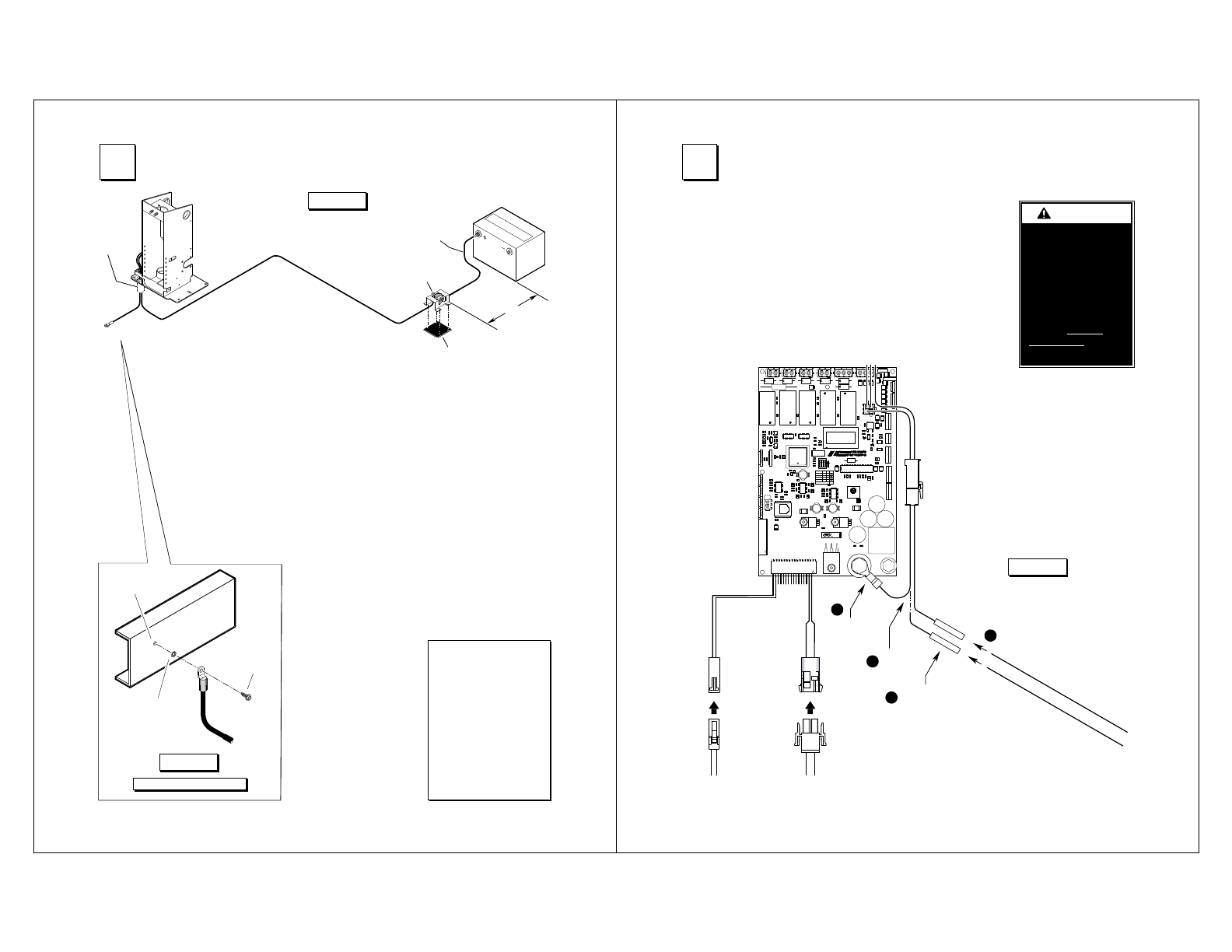
1. Drill 1-1/8” diameter grom-
met access hole. Check
under the vehicle for
obstructions.
2. Insert grommet. Secure
grommet with two self-tap
screws.
e
l
b
a
C
r
e
w
o
P
.
x
u
A.
t
a
B
.
so
P.
g
e
N
"
4
x
"
4
x
"
8
/
1
c
i
ts
a
l
P
"
2
1
.
xa
M
t
i
u
c
ri
C
y
r
t
n
e
S
d
a
e
L
el
b
a
C
t
e
m
mo
r
G
d
n
u
or
G
e
l
b
a
C
e
m
a
r
F
eb
uT
3. Route ground and power
cables through grommet.
Route cables clear of
exhaust, other hot areas
and moving parts.
4. Connect ground cable to
vehicle framing member
(see detail below).
5. Attach power cable to
Auxiliary terminal of
Circuit Sentry. Attach one
end of 18" lead cable to
the Battery Circuit Sentry
terminal.
5/16"
External Tooth
Star Washer
9/32" Diameter
Pilot Hole
Thread Cutting
Screw
&IGURE/
Locate Circuit Sentry within
12" of positive (+) battery
terminal. Mount Circuit
Sentry with four self-tap
screws. Sandwich 1/8"
x 4" x 4" plastic between
Circuit Sentry and mount-
ing surface.
6. Carefully connect opposite
end of lead cable to Posi-
tive (+) post of battery.
Ground Cable Mounting
&IGURE.
Ground Cable
Lift mounted ground
cable ground cable must
be mounted to a vehicle
framing member to pro-
vide optimum ground.
3!TTACH0OWERAND'ROUND#ABLE
Vehicle and Lift Interlock
A 2-circuit lift/vehicle interlock
interface harness is provided inside
the tower cover. The Grey/Red wire
is connected to the battery power
stud. A butt connector is provided
on the Yellow/Light Blue wire.
To meet minimum NHTSA require-
ments, connect vehicle interlock
signal wires as detailed in Figure P
(Steps 1-4):
Optional Interlock Kits
Universal Interlock Kit 30940K
is available for easy interface
with vehicle OEM electronic
signals.
Note: Detailed installation
instructions are supplied with
interlock kit(s).
R/YG
UB .TL/Y
KB
NB
W
K
B
Cut
wire.
Install butt
connector.
Threshold Warning
Sensor Harness
Door Cut-Out
Switch Harness
Connect vehicle
interlock signal wires.
Disconnect
and discard.
R
/
Y
G
)
l
a
n
g
i
S
e
r
u
c
e
S
e
l
c
i
h
e
V
(
)
l
a
n
g
i
S
d
e
w
o
t
S
t
f
i
L
(
U
B
.
T
L
/
Y
KB
Y
G
F1
R17
+
C7
+
U11
+
C1
C53
R64
U8
W9
J8
4
3
2
R73
1
J5
29 18
7
R43
R32
1
21W
R28
2
1
D14
C19
C17
R37
1
W20
R5
R63
1
K5
1
U7
R20
R59
C54 D12
D1
Q6
C43
Q4
R65
C52
C37
R53
R67
C23
R1 R9
C4
3
W10
2
1
W8
R22
2
1
R54
R70
R19
D32
C45
C29
R10
Q3
R25
R49
D8
C21
C18
D2
R71
D15
R14
K3
D9
C36
R38
R6
D18
D16
C38
R72
31W
D19
Q7
21
J6
C15
W6
2
1
Y1
01C
D27
C35
C25
R66
C33
D4
7R
+
R18
C31
D10
R13
C51
06R
D24
C20
C34
L3
C39
D28
C26
C9
D22
C8
C24
R15
D3
R35
C32
C41
K2
R50
C30
1
R47
R57
R4
D23
R46
40
+
R42
R12
R39
D7
C42
K6
C28
R24
D6
U3
D5
C27
J9
D29
R68
R55
R34
C14
R29
R44
R33
C6
R27
R40
R45
R11
C13
R2
R41
R31
5W
Q2
R69
R51
R8
R48
Q1
W16
3
W11
D30
2
1
R58
R16
R21
R30
K1
321
ON
ON
ON
S1
+
+
C46
D21
R26
11
C
R3
K4
C5
C12
U10
D26
D17
7 6 5 432
D13
U9
+
1
71W
C16
Q5
R56
D11
C47
C22
W7
D31
+
C40
2
1
+
C3
+
R36
R52
R23
D20
U5
141W
+
100024-001
ESD HAZARD
CAUTION!
REVISION
MED-LO
LOW
SPEED
ON
OFF ON
ON
OFFON
OFF OFF
1 2
ENABLE ON
TRIFOLD
3
ON
BUZZER
12V
GND
GND
12V
12V
MED-HI
HIGH
1
U
21U
+
C2
+
C50
4W
3W
1
W
1
2W
U4
L2 L1
J4
COUNTER
BARRIER
LIFT
K
C
O
LR
ET
N
I
rosn
eS
dl
o
h
ser
hT
t
imiL
dlofn
U
timi
L
dloF
timi
L
nwoD
timi
L
r
e
i
rraB
t
i
miL
yol
peD
ti
mi
L
wotS
ti
m
iL ro
ol
F
ti
miL
p
U
timiL rooD
J2
U6
2 3 123123123123
45
J1
J1 J3
1
3
4
2
&IGURE0
W
ARNING
Install and verify
proper operation of
all NHTSA mandated
interlocks as
specified. Failure
to do so will result
in a non-compliant
installation and may
result in serious
bodily injury and/or
property damage.
4#ONNECT)NTERLOCK
Ground Cable Corrosion:
When mounting ground
cables, remove undercoat-
ing, dirt, rust, etc. from
framing member around
mounting holes (minimum
5/8” diameter area). Ap-
ply protective coating to
mounting holes to prevent
corrosion. Failure to do
so will void warranty of
certain electrical compo-
nents.
Braun Corporation FMVSS No. 403 Quick Reference Installation Sheet 31312
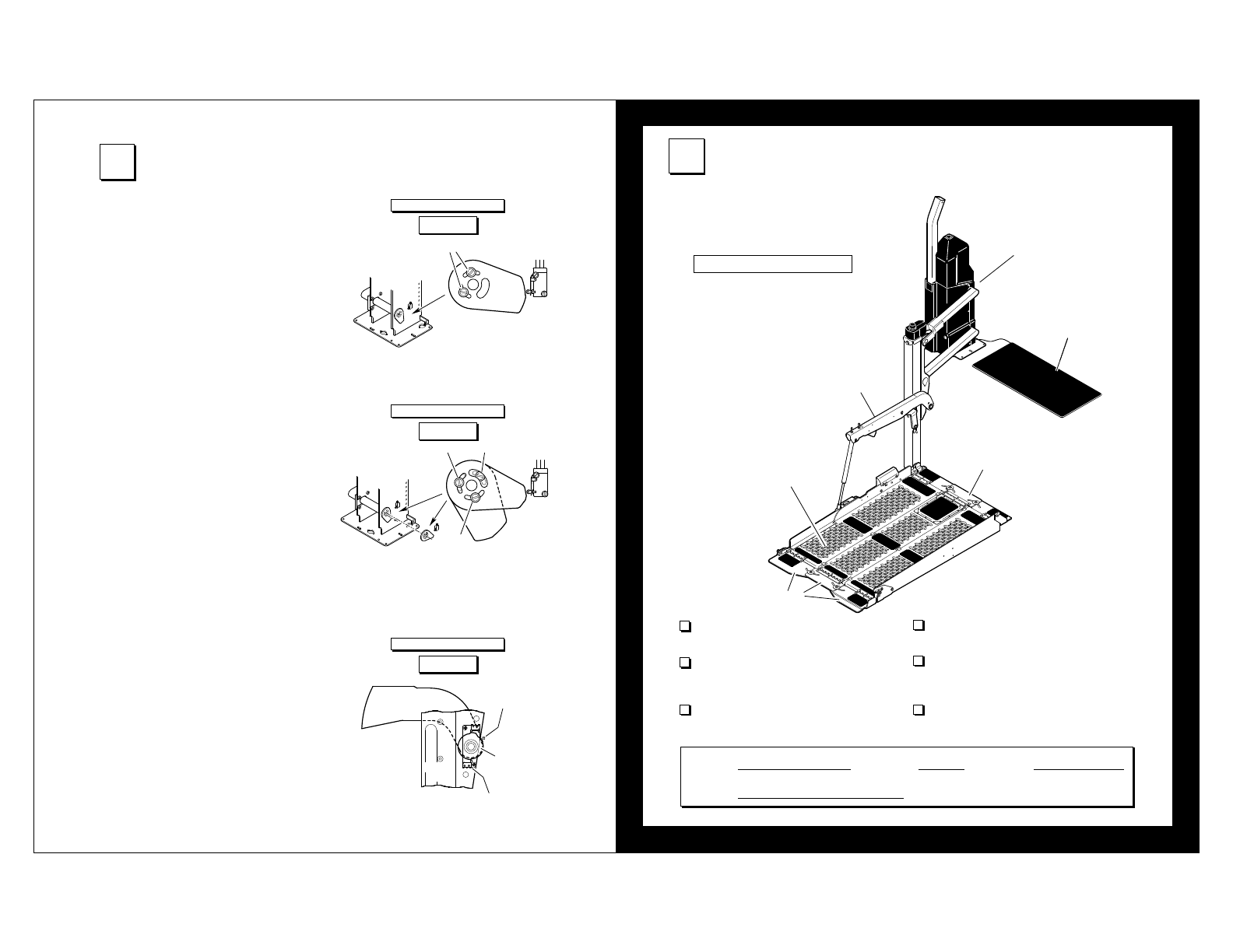
Cam
Switch
Screws
Inner
Cam
C
A B
Outer
Cam Switch
Switch
Arm
Vertical
Arm
Deploy Limit Switch
Screw
Cam
Stepwell Application
Dropped Floor Application
Deploy Limit Switch
&IGURE1
&IGURE2
&IGURE3
Floor Level Cam Adjustment:
The floor level cam(s) are located on the lower drive
arm shaft, on the rear side of the frame tube (under
the cover). Adjust per application.
• Stepwell Application (Figure Q)
1. Position platform at floor level.
2. Loosen the two cam screws.
3. Adjust the cam for proper switch activation.
4. Tighten the two cam screws.
• Dropped Floor Application (Figure R)
• Up-Stop Adjustment (inner cam and switch):
1. Position platform at original floor height
(full up position).
2. Loosen screws A, B and C.
3. Adjust the inner cam for proper switch
activation.
4. Tighten screw B.
• Floor Level Adjustment (outer cam and
switch):
Activated when the platform switches from the
up/down positions to the stow/deploy positions.
1. Position platform at lowered floor level.
2. Loosen screws A and C.
3. Adjust the outer cam until the floor level
switch activates.
4. Tighten screws A and C.
Deploy Limit Switch Adjustment (Figure S)
This switch adjusts the angle of the platform when
positioned at floor level. The platform should be
level with the van floor. The switch is located on the
vertical arm where the switch arm pivots.
1. Position platform at floor level.
2. Loosen the screw that secures the cam to the
vertical arm.
3. Level platform using a level (or as needed).
4. Adjust cam so the deploy limit switch activates.
5. Tighten screw.
6. Verify position and check level.
5,IMIT3WITCH!DJUSTMENT
The outer barrier will not raise if occupied by at
least 25 pounds.
An audible warning will activate if at least 25
pounds is on the threshold area when the plat-
form is at least one inch below floor level.
Raising the platform more than 3” off of the
ground is prevented unless the outer barrier is
raised.
Verified:
Vehicle movement is prevented unless the
platform is fully stowed.
Lift operation shall be prevented unless the
vehicle is stopped and vehicle movement is
prevented.
The platform will not fold/stow when at least
50 pounds is on the platform.
6&-633#ERTIlCATION#HECKLIST
-USTBE#OMPLETEDAND3IGNED
2%15)2%$"9&%$%2!,,!7
2%15)2%$"9&%$%2!,,!7
The operations listed below must be
functionally verified. This lift is not available
for use unless these operations have been
verified by the installerʼs signature below.
DOT — Private Use Lift
Threshold
Warning Sensor
Audible
Threshold
Warning
Inboard
Locator
Platform
Switch Arm
Outer Barrier
Verified By:
Process, fold and insert completed document in
the lift-mounted operatorʼs manual storage pouch.
Signature Required
Lift Model: Series No: Serial No:
Braun Corporation FMVSS No. 403 Quick Reference Installation Sheet 31312
A
,IFT/PERATING)NSTRUCTIONS
F
E
W
ARNING
Whenever a
passenger is on the
platform, the:
• Passenger must
face outward
• Wheelchair brakes
must be locked
• Inboard locator and
outer barrier must
be UP.
Failure to do so may
result in serious
bodily injury and/or
property damage.
Before lift operation, park the
vehicle on a level surface, away
from vehicular traffic. Place the
vehicle transmission in “Park”
and engage the parking brake.
Photos appearing in the Lift
Operating Instructions depict lift
functions being activated by lift-
mounted control switches only.
Lift-posted Warnings and Lift
Operating Instructions decal
31185 provides lift operating in-
structions. Replace any miss-
ing, worn or illegible decals.
Follow the Manual Operating
Instructions in event of power
or equipment failure. Do not
use electrical override to oper-
ate the lift when a passenger is
on the platform.
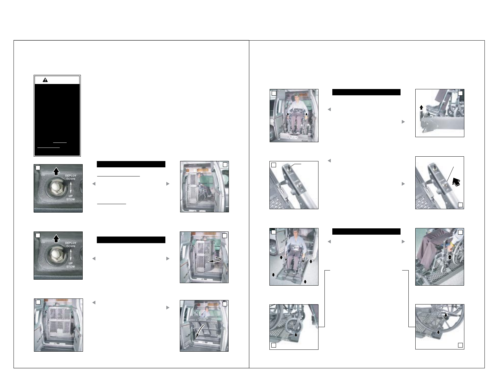
TO OPEN DOOR(S):
Power Door Operator(s):
Press the DEPLOY switch until
door(s) are fully open. Release
switch.
Manual Door(s):
Manually open door(s) fully and
secure.
TO DEPLOY PLATFORM:
1. Press DEPLOY switch until plat-
form sections open (rotate) to
full width. See Photos D and E.
Release switch.
2. Press DEPLOY switch until plat-
form until platform stops (reaches
floor level) and the inboard loca-
tor unfolds. See Photos C and F.
Release switch.
B
C
A
D
GH
J
TO UNLOAD PASSENGER:
1. Load passenger onto platform
facing outward and lock wheel-
chair brakes.
Note: Outer barrier must be UP
before loading passenger onto
platform.
2. If necessary, press the switch
arm LEVEL switch until platform
is level.
3. Press DOWN switch until the
entire platform reaches ground
level and outer barrier unfolds
fully. Release switch. See
Photo K.
LEVEL
Switch
DOWN
Switch
L
TO UNLOAD PASSENGER:
4. Unlock wheelchair brakes and
unload passenger from platform.
Note: Outer barrier must be
fully unfolded until entire wheel-
chair has crossed the barrier.
See Photos M and N.
I
K
M N
Braun Corporation FMVSS No. 403 Quick Reference Installation Sheet 31312
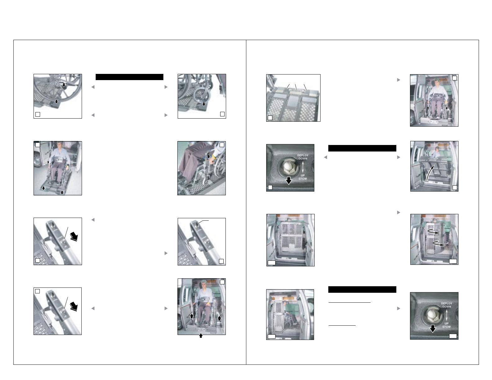
UP
Switch
,IFT/PERATING)NSTRUCTIONS
S
LEVEL
Switch
UP
Switch
TO LOAD PASSENGER:
1. Load passenger onto platform fac-
ing outward and lock wheelchair
brakes. See Photos Q and R.
Note: Outer barrier must be fully
unfolded until entire wheelchair
has crossed the barrier. See Pho-
tos O and P.
2. Press UP switch until platform
raises just above ground level.
Release switch.
3. If necessary, press the switch arm
LEVEL switch until platform is level.
4. Press UP switch until platform stops
(reaches floor level) and inboard
locator unfolds (see Photo W). Re-
lease switch.
OP
RQ
T
U
V
X
Inboard Locator
(unfolded)
TO STOW PLATFORM:
1. Press STOW switch until platform
stops (fully stowed - vertical). Re-
lease switch.
2. Press STOW switch (Photo Y) until
platform sections close (rotate) to
locked position. See Photos AA-CC.
TO CLOSE DOOR(S):
Power Door Operator(s):
Press the STOW switch until door(s)
are fully closed. Release switch.
Manual Door(s):
Manually close door(s) fully.
5. Unlock wheelchair brakes and unload
passenger from platform.
W
YZ
BB
AA
DD
CC
Braun Corporation FMVSS No. 403 Quick Reference Installation Sheet 31312
If you experience power or equipment
failure, refer to the Manual Operating
Instructions to operate the lift. Do not
use electrical override to operate lift
when a passenger is on the platform.
Refer to the Lift Operating Instructions
for all normal lift operation procedures
(such as loading and unloading pas-
sengers). Follow all Lift Operation
Safety Precautions!
&IGURE! &IGURE" &IGURE# &IGURE$
Unlocked
PLATFORM LATCH
Locked
INBOARD LOCATOR
Link
d
r
a
o
b
n
I
r
o
t
a
c
o
L
Hairpin Cap
ACTUATOR
Stow Deploy
Plug
MOTOR
Down Up
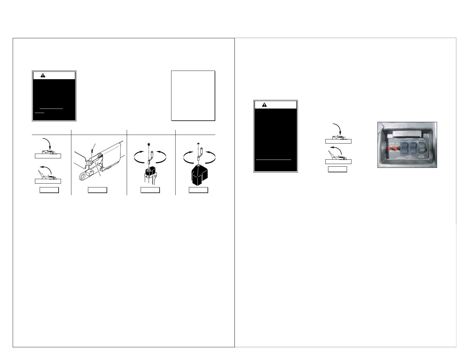
-ANUAL/PERATING)NSTRUCTIONS
TO OPEN DOOR(S):
Manually open door(s) fully and
secure.
TO DEPLOY PLATFORM:
1. Unlock (disengage) latch
under middle platform section.
See Figure A.
2. Manually open (rotate) the
three platform sections to full
width.
3. Engage latch under middle
platform section to lock plat-
form sections at full width. See
Figure A.
4. Remove cap from top of verti-
cal arm actuator. See Figure
C.
5. Place crank handle on actuator
shaft and turn counterclock-
wise until platform reaches
floor level. See Figure C.
Remove crank handle.
W
ARNING
Do not use electrical
override to operate
lift when a passenger
is on the platform.
Doing so may result
in serious bodily
injury and/or property
damage.
TO DEPLOY INBOARD
LOCATOR:
1. Remove hairpin cotter from
inboard locator link pin. See
Figure B.
2. Remove link from inboard loca-
tor pin. See Figure B.
3. Lower (unfold) inboard locator
to vehicle floor.
TO STOW INBOARD LOCATOR:
1. Raise (fold) inboard locator to
vertical position.
2. Place link on inboard locator
pin. See Figure B.
3. Insert hairpin cotter into inboard
locator link pin. See Figure B.
Hand Crank Note:
For easier operation
of the hand crank,
press and hold the
electrical override
MANUAL/BRAKE
RELEASE switch in
the MANUAL position
while turning crank.
TO LOWER PLATFORM:
1. Remove plug from top of motor
cover. See Figure D.
2. Place crank handle on motor
shaft and turn clockwise until
platform reaches ground level.
See Figure D. Remove crank
handle.
TO RAISE PLATFORM:
1. Remove plug from top of motor
cover. See Figure D.
2. Place crank handle on motor
shaft and turn counterclockwise
until platform reaches floor
level. See Figure D. Remove
crank handle.
TO STOW PLATFORM:
1. Remove cap from top of vertical
arm actuator. See Figure C.
2. Place crank handle on actuator
shaft and turn clockwise until
platform stops (reaches full
vertical position). See Figure C.
Remove crank handle.
3. Unlock (disengage) latch under
middle platform section. See
Figure A.
4. Manually close (rotate) the
three platform sections
5. Engage latch under middle
platform section to lock platform
sections. See Figure A.
TO CLOSE DOOR(S):
Manually close door(s).
%LECTRICAL/VERRIDE)NSTRUCTIONS
Electrical Override Switches
W
ARNING
• Do not use electrical
override to operate
lift when a passenger
is on the platform.
• Override switches
must be released to
stop lift at desired
position.
Failure to follow these
rules may result in
serious bodily injury
and/or property dam-
age. &IGURE!
Unlocked
Locked
TO OPEN DOOR(S):
Manually open door(s) fully and secure.
TO DEPLOY PLATFORM:
1. Unlock (disengage) latch under middle platform
section. See Figure A.
2. Manually open (rotate) the three platform sec-
tions to full width (unfolded).
3. Engage latch under middle platform section to
lock platform sections at full width. See Figure
A.
4. Rotate the access cover to expose the override
switches. See above photo.
5. Press the two override rocker switches to
OVERRIDE.
6. Press the left toggle switch to DEPLOY until
platform reaches floor level. Release switch.
7. Press the right toggle switch to DOWN until
platform reaches ground level. Release switch.
8. To deploy (unfold) the outer barrier, press
the left toggle switch to DEPLOY until barrier
unfolds fully. Release switch.
TO OPEN DOOR(S):
Manually open door(s) fully and secure.
TO STOW PLATFORM:
1. Rotate the access cover to expose the override
switches. See above photo.
2. Press the two override rocker switches to
OVERRIDE.
3. To raise (fold) the outer barrier to vertical posi-
tion, press the left toggle switch to STOW until
barrier folds fully. Release switch.
4. Press the right toggle switch to UP until plat-
form reaches floor level. Release switch.
5. Press the left toggle switch to STOW until plat-
form reaches vertical position. Release switch.
6. Unlock (disengage) latch under middle platform
section. See Figure A.
7. Manually close (rotate) the three platform sec-
tions to closed position (folded).
8. Engage latch under middle platform section to
lock platform sections. See Figure A.
passenger only. Do not use
the electrical override to oper-
ate the lift when a passenger is
on the platform. Lift functions
operate at higher rate of speed
when using the electrical over-
ride. When using the electrical
override, the operator must stop
pressing the applicable override
switch when the lift reaches the
desired position (limit switches
will not function).
Note: Following electrical
override procedures, press the
two override rocker switches to
NORMAL. Close access cover
and press the main control
switch to STOW. Function lift
through one full cycle to ensure
proper operation.
The Electrical Override feature
is provided as a diagnostic
procedure to reset the system
and as an alternative method
of operating the lift without a
Braun Corporation FMVSS No. 403 Quick Reference Installation Sheet 31312
Proper maintenance is necessary to ensure
safe, troublefree operation. Inspecting the lift for
any wear, damage or other abnormal conditions
should be a part of your daily routine. Simple
inspections can detect potential problems.
The maintenance and lubrication procedures
specified in this schedule must be performed by
a Braun authorized service representative at the
scheduled intervals according to the number of
cycles.
The Vangater II is equipped with hardened pins
and self-lubricating bushings to decrease wear,
provide smooth operation and extend the service
life of the lift.
When servicing the lift at the recommended inter-
vals, inspection and lubrication procedures speci-
fied in the previous sections should be repeated.
Clean the components and the surrounding area
before applying lubricants. LPS2 General
Purpose Penetrating Oil is recommended where
Light Oil is called out. Use of improper lubricants
can attract dirt or other contaminants which could
result in wear or damage to the components.
Platform components exposed to contaminants
when lowered to the ground may require extra
attention.
Lift components requiring grease are lubricated
during assembly procedures. When these com-
ponents are replaced,
grease must be
applied during instal-
lation procedures.
Specified lubricants
are available from
The Braun Corpora-
tion (part numbers
provided below).
All listed inspection,
lubrication and main-
tenance procedures
should be repeated at
“750 cycle” intervals
following the scheduled “4500 Cycles” maintenance.
These intervals are a general guideline for scheduling
maintenance procedures and will vary according to
lift use and conditions. Lifts exposed to severe condi-
tions (weather, environment, contamination, heavy
usage, etc.) may require inspection and maintenance
procedures to be performed more often than speci-
fied.
Discontinue lift use immediately if maintenance
and lubrication procedures are not properly per-
formed, or if there is any sign of wear, damage or
improper operation. Contact your sales representa-
tive or call The Braun Corporation at 1-800-THE LIFT.
One of our national Product Support representatives
will direct you to an authorized service technician who
will inspect your lift.
W
ARNING
Maintenance and lu-
brication procedures
must be performed
as specified by an
authorized service
technician. Failure
to do so may result
in serious bodily
injury and/or prop-
erty damage.
-AINTENANCEAND,UBRICATION
Switch Arm
Main Drive Ballscrew
(in Frame Tube - hidden)
Lift Rod
Downstop
(hidden)
Platform Fold
Mechanism
(Under Cover)
Inboard Locator
Latch Mechanism
Platform
Hinges (6)
Outer Barrier Latch
Drive Arms
Specified (recommended) Available Braun
Lubricant Type Lubricant Amount Part No.
Light Grease Lubriplate 14 oz.
(Multipurpose) Can
15807
15806
15805
Light Penetrating Oil LPS2, General Purpose 11 oz.
(30 weight or equivalent) Penetrating Oil Aerosol Can
Stainless Stick Door-Ease 1.68 oz.
Style (tube) Stick (tube)
#YCLES
Apply Light Oil - See Lubrication Diagram
Apply Light Oil - See Lubrication Diagram
Apply Light Oil - See Lubrication Diagram
Apply Light Oil - See Lubrication Diagram
Apply Light Oil - See Lubrication Diagram
Apply Light Oil - See Lubrication Diagram
Apply Light Grease - See Lubrication Diagram
Tighten, repair or replace if needed.
Tighten, resecure or replace if needed.
Resecure, replace damaged parts or otherwise
correct as needed. Note: Apply lubricant during
reassembly procedures.
Perform all procedures listed in previous section also
#YCLES
Apply Light Grease - See Lubrication Diagram
Add Lucas Heavy Duty Oil Stabilizer
#YCLES
Perform all procedures listed in previous sections also
Repeat all previously listed inspection, lubrica-
tion and maintenance procedures at 750 cycle
intervals.
#ONSECUTIVE
#YCLE
)NTERVALS
Platform fold mechanism
Ballscrew / main drive
Clean ground cable at battery and frame
Check power cables
Door-Ease
Light Oil
Light Grease
Downstop pivot points (2)
Upper lift rod pin
Lower lift rod pin
Kickout spring (located in switch arm)
Platform hinges (6)
Outboard barrier latch
Inboard locator latch mechanism
Check mounting hardware
Check all fasteners (snap rings, nuts, hairpins, etc.)
Check all pivot points for excessive wear
