Braun Wheelchair 32221 Users Manual
32221 to the manual 1762272b-cd66-4897-883c-30a85bd40a8b
2015-02-02
: Braun Braun-Wheelchair-32221-Users-Manual-409692 braun-wheelchair-32221-users-manual-409692 braun pdf
Open the PDF directly: View PDF ![]() .
.
Page Count: 18
Century
DOT — Public Use Lift
DOT — Public Use Lift
“DOT — Public Use Lift” verifies that this platform lift meets the
“public use lift” requirements of FMVSS No. 403. This lift may be
installed on all vehicles appropriate for the size and weight of the
lift, but must be installed on buses, school buses, and multi-
purpose passenger vehicles other than motor homes with a gross
vehicle weight rating (GVWR) that exceeds 4,536 kg (10,000 lb).
Public Use Wheelchair Lifts
03
HZg^Zh
HZg^Zh
C8A
C8A
Series 03
Service Manual for:
32221
January
2006
"Providing Access to the World"
International Corporate Hdqrs: P.O. Box 310 Winamac, IN 46996 USA
1-800-THE LIFT® (574) 946-6153 FAX: (574) 946-4670
®
®
W
A
R N I N G
Read manual
before installing
or servicing lift.
Failure to do so
may result in
serious bodily
injury and/or
property damage.
ual
Man
Patent #5,261,779
Patent #6,065,924
Patent #6,238,169
Patent #6,464,447
Patent #6,599,079
Patent #6,692,217
Patent #6,739,824
Patents Pending
Patent #5,261,779
Patent #6,065,924
Patent #6,238,169
Patent #6,464,447
Patent #6,599,079
Patent #6,692,217
Patent #6,739,824
Patents Pending
Patent #5,261,779
Patent #6,065,924
Patent #6,238,169
Patent #6,464,447
Patent #6,599,079
Patent #6,692,217
Patent #6,739,824
Patents Pending
Patent #5,261,779
Patent #6,065,924
Patent #6,238,169
Patent #6,464,447
Patent #6,599,079
Patent #6,692,217
Patent #6,739,824
Patents Pending
Braun NCL Series
Braun NCL Series

NCL917IB
e5*72/245*95/54*0110*00
1-800-THE LIFT™
BRAUNLIFT.COM™
The Braun Corporation
DOT Public Use Lift MODEL#
Max. Lifting Capacity - 800 lbs.
PATENT
PENDING- 5,261,779-6,065,924-6,238,169-6,46
4,447-6,599,079-6,692,217-6,739,824
MFG DATE
55 14CG
PUMP CODE CYLINDER
03-00025
SERIAL NUMBER
11/01/05
We at The Braun Corporation wish to express our fullest appreciation
on your new purchase. With you in mind, our skilled craftsmen have designed and
assembled the finest lift available.
This manual provides service-related material. Refer to the FMVSS No. 403
Quick Reference Installation Sheet for installation instructions, operating instructions
and maintenance procedures.
Braun Century Series™ lifts are built for dependability and will provide years of
pleasure and independence as long as the lift is installed and serviced as specified by
a Braun certified technician, and the lift is operated by an instructed person.
Sincerely,
THE BRAUN CORPORATION
Ralph W. Braun
Chief Executive Officer
OWNER'S WARRANTY REGISTRATION
PURCHASED FROM
DATE INSTALLED
NAME
ADDRESS
CITY
TELEPHONE
TO VALIDATE WARRANTY
REGISTRATION CARDS MUST BE RETURNED TO THE BRAUN CORPORATION.
OWNER
STAT E ZIP
Sample Warranty/Registration Card
Two Braun Serial No./Series No. identification tags (shown below) are posted on the lift.
One I.D. tag is posted on the opposite pump side vertical arm. A second I.D. tag is located
on the opposite pump side tower. Both I.D. tags provide the product identification infor-
mation provided on the warranty/registration card. Record the information in the space
provided (or document on a copy). This information must be provided when filing
a warranty claim or ordering parts.
Warranty and Registration Instructions
Immediately upon receiving the lift, examine the
unit for any damage. Notify the carrier at once
with any claims.
Two warranty/registration cards (shown right) are
located in the lift-mounted manual storage pouch.
The sales representative must process one of the
cards. The consumer must fill out the other card
and mail it to The Braun Corporation. The war-
ranty is provided on the back cover of this manual.
The warranty cards must be processed to
activate the warranty.
Congratulations
Model No.
Series No.
Serial No.
Pump Code
Cylinder Code
Date of Manufacture
6DPSOH6HULDO1R6HULHV1R,GHQWLÀFDWLRQ7DJ
NCL917IB-03-00025-55-14CG
Serial No.Model No. Cylinder Code
Series No. Pump Code

Page 1
Contents
Troubleshooting
&HUWLÀFDWLRQ&KHFNOLVW'LDJQRVWLF3URFHGXUHV .......2-3
/LIW(OHFWULFDO6FKHPDWLF .............................................. 4
/LIW:LULQJ'LDJUDP ...................................................... 5
6ZLWFKDQG6HQVRU/RFDWLRQV ..................................... 6
/&'(UURU&RGHV .......................................................... 7
+\GUDXOLFV
+\GUDXOLF6FKHPDWLF .................................................... 8
+\GUDXOLFV3DUWV/LVW .................................................... 9
+\GUDXOLFV'LDJUDP .................................................... 10
5HSDLU3DUWV
3XPS0RGXOH
3XPS0RGXOH3DUWV/LVW ........................................11
3XPS0RGXOH'LDJUDP ......................................... 12
/LIW([SORGHG9LHZ
5HSDLU3DUWV/LVW .................................................... 13
([SORGHG9LHZ........................................................ 14
Page 2
Certification Checklist Diagnostic Procedures
8VHWKHIROORZLQJDGMXVWPHQWSURFHGXUHVVKRXOGWKHOLIWQRWIXQFWLRQDVGHVFULEHGLQWKHFHUWLÀFDWLRQFKHFNOLVW
7KHVHSURFHGXUHVPXVWEHIROORZHGLQRUGHUIRUWKHOLIWWREH)0966FRPSOLDQW
9HKLFOHPRYHPHQWLVSUHYHQWHGXQOHVVWKHSODWIRUPLVIXOO\VWRZHG
9HULI\OLIWVWRZHGVLJQDOSLQRQWKHSXPSPRGXOHKDVDYROWRXWSXWVLJQDOIURPOLIW25SLQKDVD
JURXQGVLJQDOIURPOLIWGHSHQGVRQLQWHUORFNXVHG
5HIHUWRWKHLQWHUORFNLQVWDOODWLRQLQVWUXFWLRQV
/LIWRSHUDWLRQVKDOOEHLQKLELWHGXQOHVVWKHYHKLFOHLVVWRSSHGDQGYHKLFOHPRYHPHQWLVSUHYHQWHG
9HULI\YHKLFOHVHFXUHVLJQDOSLQKDVDYROWLQSXWVLJQDOIURPLQWHUORFN
5HIHUWRWKHLQWHUORFNLQVWDOODWLRQLQVWUXFWLRQV
7KHSODWIRUPZLOOQRWIROGVWRZZKHQRFFXSLHG
3RVLWLRQWKHSODWIRUPDWWKHÁRRUOHYHOORDGLQJSRVLWLRQ
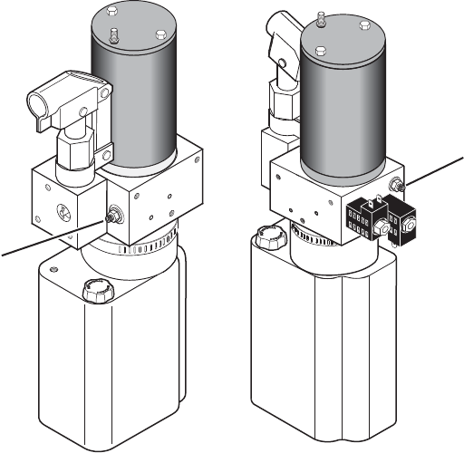
/RRVHQWKHORFNQXWRQWKHGXDOUHOLHIYDOYHDGMXVWPHQWGRQRWUHPRYHORFNQXW6HHLOOXVWUDWLRQEHORZ
7XUQWKHDGMXVWPHQWVFUHZFRXQWHUFORFNZLVHXQWLOWKHSODWIRUPGRHVQRWIROGZKHQWKH)ROGEXWWRQLV
SUHVVHG
7XUQWKHDGMXVWPHQWVFUHZFORFNZLVHLQWXUQLQFUHPHQWVDQGSUHVVWKH)ROGEXWWRQXQWLOWKHSODWIRUP
IROGVFRPSOHWHO\1RWHUHWXUQWKHSODWIRUPWRÁRRUOHYHOSRVLWLRQDIWHUHDFKDWWHPSWWRIROGWKHSODWIRUP
7XUQWKHDGMXVWPHQWVFUHZDQDGGLWLRQDOWXUQDIWHUWKHSODWIRUPIROGVVXFFHVVIXOO\
7LJKWHQWKHORFNQXWZLWKRXWPRYLQJWKHDGMXVWPHQWVFUHZ
9HULI\WKHSODWIRUPZLOOQRWVWRZZKLOHRFFXSLHG
Platform Relief Valve
Adjustment
(Located beside Backup Pump)
DO NOT adjust this valve!
(Located beside Solenoid Valves)
Page 3
Certification Checklist Diagnostic Procedures
7KHLQQHUUROOVWRSZLOOQRWUDLVHLIRFFXSLHG
&DOO3URGXFW6XSSRUW
7KHRXWHUEDUULHUZLOOQRWUDLVHLIRFFXSLHG
&DOO3URGXFW6XSSRUW
9HULI\SODWIRUPOLJKWLQJZKHQOLIWLVGHSOR\HG
5HSODFHEXOEVLQWKHOLJKWKRXVLQJ
&KHFNIXVHDPSIXVHRQFLUFXLWERDUG)
$QDXGLRZDUQLQJDQGYLVXDOZDUQLQJIRUSXEOLFOLIWVZLOODFWLYDWHLIWKHWKUHVKROGDUHDLVRFFXSLHGZKHQWKHSODW
IRUPLVDWOHDVWEHORZÁRRUOHYHO
5HPRYHWKHWKUHVKROGZDUQLQJSODWH
9HULI\WKHWKUHVKROGVWULSVZLWFKFRQQHFWRUVDUHFRQQHFWHGVHHLOOXVWUDWLRQRQ3DJH
5HSODFHWKHWKUHVKROGVWULSVZLWFK
5HLQVWDOOWKHWKUHVKROGZDUQLQJSODWH
/RZHULQJWKHSODWIRUPEH\RQGWKHLQQHUUROOVWRSORFNLQJSRVLWLRQLVDOORZHGRQO\ZKHQWKHLQQHUUROOVWRSLVORFNHG
LQSRVLWLRQ
&DOO3URGXFW6XSSRUW
• Lift platform movement shall be interrupted unless the outer barrier is raised and the outer barrier latch is posi
WLYHO\HQJDJHG
&DOO3URGXFW6XSSRUW

Page 4
Lift Electrical Schematic
NCL917-03-025.ai
BK(6)BK(4)
GN(20)
OR
OR
RD
RD
YL
PR
GN
GN
YL(26)
RD(26)
GN(26)
YL(26)
RD(26)
GN(26)
BU(16)
GN(20)
GN(20)
GN(20)
PK(20)
WH(20)
WH(20)
GN(20)
GN(20)
GN(20)
LT. GN / GN(18)
GN(14)
BK(18)
UP/FOLD
SOLENOID
RD (2)
PUMP
RD(14)
CIRCUIT
SENTRY
(CIRCUIT BREAKER)
PLATFORM LIGHTS (OPTION)
RD(4)
RD(2)
HYDRAULIC
(UP)
M
GROUND
POWER
STUD
PUMP BODY
GROUND
RD(20)
DOWN
SOLENOID
NOTE: ALL WIRES ARE 22 GA.
UNLESS OTHERWISE NOTED.
DUAL RELIEF
SOLENOID
INTERLOCK
LED
THRESHOLD
WARNING
LIGHT
THRESHOLD
WARNING
BEEPER
OUTBOARD
BARRIER RAISED
SENSOR
BU(32)
YL(32)
GN(32)
RD(32)
BK(32)
WH(32)
BU(32)
YL(32)
GN(32)
RD(32)
BK(32)
WH(32)
GN(20)
RD(14)
SWITCH BOX
LIFT
6
5
4
3
J2
6
5
4
3
P2
22
11
2
1
P4
UP
DOWN
UNFOLD
FOLD
4
3
5
6
1
2
P9
2
1
2
1
1
2
1
2
BK(20)
BU(16)
RD(20)
WH(20)
WH(20)
PK(20)
1
6
P8
3
2
4
5
GN(20)
GN(20)
RD(18)
RD(20)
BK(18)
BK(18)
BK(18)
WH(20)
RD(20)
BK(18)
RD(18)
BK(18)
BK(18)
GY/RD(18)
BK(20)
BK(20)
GY/RD(18)
2
1
P7
4
3
1
2
1
2
1
2
1
2BK(18)
RD(18)
BK(20)
RD(20)
RD(18)
BK(18)
WH(20)
GN(20)
13
15
6
14
7
12
10
11
17
8
9
18
P5
P28J28
P16
J20P20
J20P20
J16
P16
J16
4
5
16
3
1
2
2
3
2
3
11
YL
PR
BU
3
2
1
J25
P25
J26
P27
J27
BRIDGE
MICROSWITCH
MAGNET
OR
RD
GN
YL(26)
RD(26)
GN(26)
IB RAISED
SENSOR
THRESHOLD
SENSOR
2
3
2
3
11
MAGNET
WH
WH
BK
BK
BU
OR
RD
GN
WH
BK
2
1
2
1
NO
NC
C
BU(16)
BU(16)
BU(16)
LIFT POWER SWITCH
2
1
P6
4
3
5
6
BK(24 GA COPPER)
BK(24 GA COPPER)
BK/WH(24 GA SILVER)
BK/WH(24 GA SILVER)
1
2
1
2
P32
J32
RD
RD
BK
BK
GN
GN
WH
WH
6
8
3
7
P13
4
5
2
1
6
8
3
7
4
5
2
1
OR
OR
BK
RD
WH
GN
1
2
1
2
J15
P15
1
2
1
2
P15 J15
LIFT CONTROL MODULE
J3
2
1
J4
4
3
5
6
1
2
J9
1
6
J8
3
2
4
5
2
1
J6
J13
4
3
5
6
2
1
J7
3
4
13
15
6
14
7
12
10
11
17
8
9
18
J5
5
4
16
3
1
2
GN
BK
GN
BK
BK
RD
RD
RD
ROTARY
POSITION
SENSOR
FLOOR LEVEL
MEMORY SET
PUSH BUTTON
COUNTER
GN
RD
RD
J30
BK BK
RD
POS.+
E
NEG. -
RD
BK
BK
GN
GN
3
12
2
6
5
4
1
7
8
9
10
11
3
12
2
6
5
4
1
7
8
9
10
11
P3
C
E
F
C
DD
A A
BB
E
F00000
C1
WH
BK
IB OCCUPANCY
MICROSWITCH
NO
NC
C
GROUND
DETECT
SENSOR
2
3
1
P26
MAGNET
N S
N S
N S
M
BATTERY
CHASSIS GROUND
CIRCUIT BREAKER
CONNECTORS
JUNCTION
MOTOR
MICROSWITCH
PRESSURE SWITCH
DIODE
SWITCH
SOLENOID
SYMBOL DESCRIPTION
SOLENOID
LED
COUNTER
MAGNETIC SWITCH
LIGHT
BEEPER
ROTARY POSITION SENSOR
NO
NC
C
+
E
S
N
-
00000
MAGNET
NC
GN(20)
INTERLOCK
J21
8
9
P21
6
7
5
2
3
4
1
8
9
6
7
5
2
3
4
1
GY/RD(18)
BK(20)
BK(20)
WH(20)
WH(20)
BK(20)
RD(20) RD(20)
GN(20)
YL/LT. BU(20)
VEHICLE SECURE SIGNAL GY/RD(18)
LIFT STOWED SIGNAL
1
2
1
2
3
4
3
4
J31P31
C5
STOW INTERLOCK (+)
MICROSWITCH NO
NC
C
GN(20)
WH(20)
C6
STOW INTERLOCK (-)
MICROSWITCH NO
C
(+12V OUTPUT)
(GROUND)
OR
(+12V INPUT)
Note: Shown with lift in stowed position.
NO
C
NO
C
NO
C
NO
C
Page 5
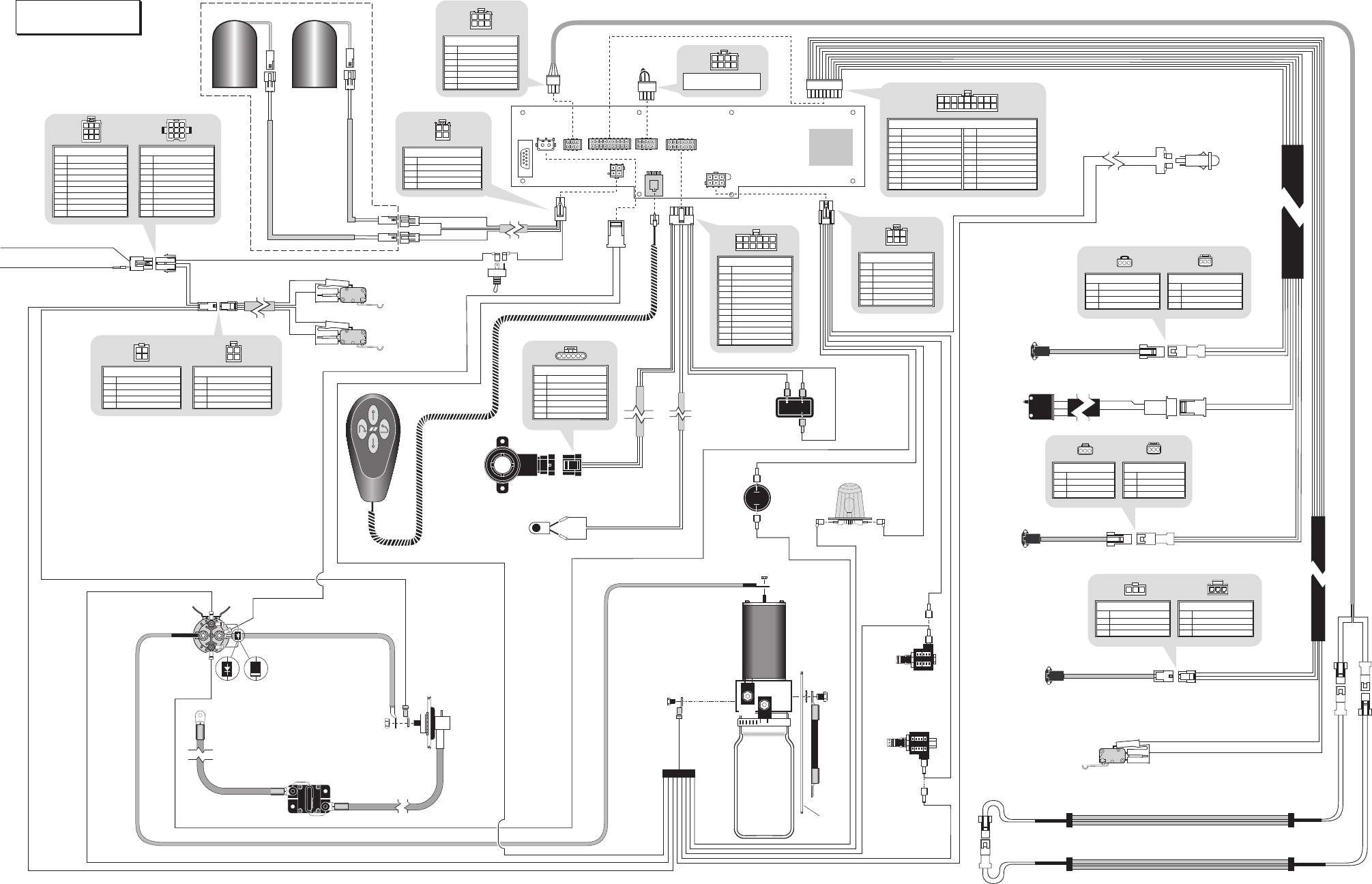
Lift Wiring Diagram
Platform Lights (Option)
Circuit Sentry
(Circuit Breaker)
Bat.
Aux.
Lift
Power Cable
205-0712-37
Pump Module
Power Feed
26082A-4
Connects to
Vehicle Battery
(+) Positive Post
Lead Wire
13362A
GN(20)
)
0
2
(KB
RD(20)
or
Note polarity of diode. It
must be oriented as shown.
Detail at left shows two different
styles of diode identification.
)
4
1(NG
RL3
BK(4)
GN(20)
BK
RD
GN(20)
WH(20)
)
0
2
(N
G
)41
(D
R
dnuo
rG
p
muP
Ground
NCL917-03-024.ai
BU(16)
BK(24) COPPER
BK(24) COPPER
BK / WH(24) SILVER
BK(24 GA COPPER) BK
GN
WH
RD
BK / WH(24 GA SILVER)
BK / WH(24) SILVER
BK(24 GA COPPER)
BK / WH(24 GA SILVER)
FS2
FS10
FS3
FS5
FS8
FS9
FS12
FS13 FS14
FS7
FS4
FS1
FS20
FS21
FS11
WH(20)
GN(20)
PK(20)
Up/Fold
Solenoid
Motor Power Feed Wire
Beeper
Threshold
Warning
Light
Outboard
Barrier
Raised Sensor
Ground
Detect
Sensor
Lift
Control
Module Interlock LED
Back
Plate
(Side view of
solenoids removed
from pump.)
Hydraulic
Pump
J7
PURPLE
YELLOW
BLUE
GREEN (To J27)
ORANGE (To J27)
RED (To J27)
NOT USED
WHITE (To P25)
BLACK (To P25)
6
5
4
3
2
1
COLORNO.
18-COND WIRE CODE
7
8
9
11 10
13 12
14
1516
17
18
2 1
43
5
67
8
9
J9
J8
J4
J3
B
A
T
A
U
X
GN(16)
RD(20)
GN(16)
J28 P28
P15J15
J15P15
P32J32
J25 P25
P26 J26
P27
P8
P5
P3
P9
P6
P7P16
P20
J20
P20
J20
J30
J16
P16 J16 RL5 RL6
7
L
R
2
L
R
1
L
R
4
L
R
J27
31030A45
31010FA - Front Pump
31010RA - Rear Pump
30433A60
985-A1534NA
985-2535NA
+-
Down
Threshold Sensors
IB Raised
Sensor
Counter
BLACK (To C1)
WHITE (To C1)
NOT USED
GREEN (To P28)
ORANGE (To P28)
RED (To P28)
NOT USED
NOT USED
NOT USED
15
14
13
12
11
10
COLORNO.
16
17
18
Down
Dual Relief
Power
Stud
31221A
31221A
RD(4)
RD(14)
RD(2)
RD(2)
BK(6)
Lift Power
Switch
BK
RD(20)
GY/RD(18)GY/RD(18)
985-0531NA
985-2541NA
A N
2
3
5
2
-589
26161A-84
A N3352-589
RD(20)
RD(20)
GN(20)
WH(20)
BK(20)
BK(20)
BK(20)
RD(20)
BK(20)
4
5A
3
3
0
1
3
31033A99
)81(KB
)81(KB
)
8
1
(KB
)
8
1
(KB
RD(20)
BK(20)
RD
GN
J6 J13
J5
+-
-
E
+
P13
BU(16)
BU(16) WH
BK
Bridge
Microswitch
COM
NO
NC
30433A60
GREEN(26)
RED(26)
YELLOW(26)
3
2
1
COLORNO.
3-COND WIRE CODE
GREEN
RED
ORANGE
3
2
1
COLORNO.
3-COND WIRE CODE
1
2
1
2
3 2 1 1 2 3
GREEN(26)
RED(26)
YELLOW(26)
3
2
1
COLORNO.
3-COND WIRE CODE
GREEN
RED
ORANGE
3
2
1
COLORNO.
3-COND WIRE CODE
3 2 1
1 2 3
BLACK (To FS20)
RED (To FS21)
NOT USED
NOT USED
RED (To J30)
GREEN (To J30)
6
5
4
3
2
1
COLORNO.
12-COND WIRE CODE
BLACK (To J30)
GREEN (To FS12)
BLACK (To FS14)
RED (To FS13)
NOT USED
NOT USED
12
11
10
9
8
7
123456
78910
11
12
PINK(20)
BLACK(20)
BLUE(16)
NOT USED
RED(20)
WHITE(20) & WHITE(20)
6
5
4
3
2
1
COLORNO.
6-COND WIRE CODE
3 2 1
5 46
NOT USED
NOT USED
GREEN
WHITE
BLACK
RED
6
5
4
3
2
1
COLORNO.
6-COND WIRE CODE
3 2 1
5 46
3 2 1
6 57
4
8
GRAY / RED(18)
BLACK(20) & WHITE(20)
RED(20) & GREEN(20)
NOT USED
4
3
2
1
COLORNO.
4-COND WIRE CODE
2 1
4 3
Dual
Relief
1
2
2
11
2
1
2
2
1
1
2
21
1
2
21
Note: All wires 22 GA.
unless otherwise noted.
GREEN
NOT USED
NOT USED
NOT USED
D
C
B
A
COLORNO.
6-COND WIRE CODE
RED
BLACK
F
E
C1
2
1
2 2
1
2
1
1
21
2
1
Rotary
Position
Sensor
Floor Level
Memory Set
Push Button
A B C D E F
ORANGE JUMPER #1 (CAVITY #2 TO #4)
ORANGE JUMPER #2 (CAVITY #3 TO #8)
IB Occupancy
Microswitch
C-H
COM
NO
NC
WH
BK
4N.O.
N.C.
.
M
O
C
PURPLE
YELLOW
BLUE
3
2
1
COLORNO.
3-COND WIRE CODE
1 2 3
3 2 1
3
2
1
COLORNO.
3-COND WIRE CODE
GREEN(26)
RED(26)
YELLOW(26)
985-A2530NA
Switch
Box
P4
UP
DOWN
D
L
O
F
N
U
D
L
O
F
100063-001
J21P21
Interlock
Connection
VEHICLE SECURE SIGNAL +12V INPUT
LIFT STOWED SIGNAL
(Located in cavity #7 or #9 - see chart above)
31797A
31798A
WHITE(20)
GREEN(20)
RED(20)
BLACK(20)
4
3
2
1
COLORNO.
4-COND WIRE CODE
4
3
2
1
COLORNO.
4-COND WIRE CODE
GRA Y / RED(18 )
NOT USED
NOT USED
NOT USED
NOT USED
NOT USED
6
5
4
3
2
1
COLORNO.
9-COND WIRE CODE
WHITE(20)
NOT USED
BLACK(20)
9
8
7
GRAY / RED(18)
NOT USED
NOT USED
NOT USED
NOT USED
NOT USED
6
5
4
3
2
1
COLORNO.
9-COND WIRE CODE
NOT USED
YL / LT. BU(18) +12V SIGNAL
YL / LT. BU(18) GROUND SIGNAL
9
8
7
12 3
456
789
123
456
789
BK(20)
RD(20) Stow Interlock (+)
Microswitch
C-H
COM
NO
NC
C5
N.O.
COM.
N.C.
GN(20)
WH(20)
915-A2539NA
Stow Interlock (-)
Microswitch
C-H
COM
NO
NC
C6
N.O.
COM.
N.C.
YL/LT. BU(18)
GY/RD(18)
J31 P31
WHITE(20)
GREEN(20)
RED(20)
BLACK(20)
2 1
4 3
3 4
1 2
Page 6
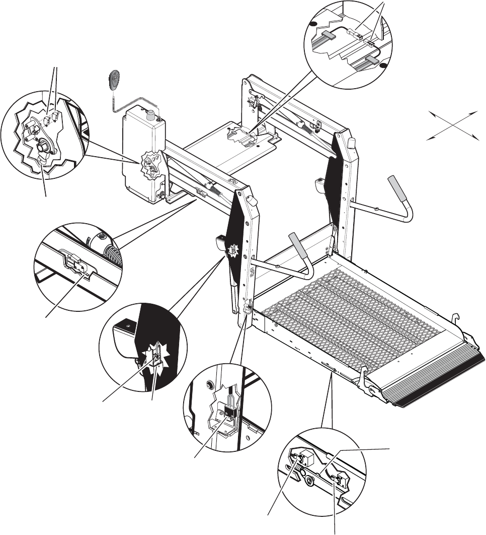
*Outboard Barrier Raised
Magnetic Sensor
30433A60
Threshold Strip Switch
31221A (Qty. 2)
*Bridging
Microswitch
31010RA (Rear Pump)
31010FA (Front Pump)
*Note: Mirror image for
right (front) pump lifts.
Inboard
Outboard
Right
Left
*IB Raised
Magnetic Sensor
31030A45
*IB Raised
Magnet
30662
*IB Occupancy
Microswitch Assy.
31643A
DOWN
FOLD
UP
UNFOLD
*Rotary Position Sensor
31194A
*Stow Microswitch
23184 (Qty. 2)
*Ground Detect
Magnetic Sensor
30433A60
*Outboard Barrier
Link / Slide Magnet Assy.
985-0201NA
Switch and Sensor Locations

Page 7
57 – Outer barrier is not up and latched and ground
detect switch did not deactivate (Century and Vista
only)
58 – Outer barrier is not up and latched and the platform
is 3” above the ground
59 – Outer barrier is not up after pausing platform travel
60 – The kickout gas springs are worn, replace before
using
75 – Low voltage detected; must turn off power switch to
reset LCD
77 – Vehicle secure interlock has not been activated
90 – Position will be set if you keep holding the button
until it beeps
91 – Position is out of a predetermined acceptable range
RIÁRRUSRVLWLRQ
92 – Bridge switch is not made, needs adjusting
93 – Inner rollstop occupied switch is not made, position
needs to be moved or switch should be adjusted
²2XWHUEDUULHULVQRWPDGHÀ[DQGWU\DJDLQ
95 – Outer barrier latch is not made (check for jumper on
Century and Vista lifts, check latch on Millennium
lifts)
99 – Controller program is not valid; replace controller
Flashing Numbers
Flashing 65 – Unfold button is pressed
Flashing 66 – Fold button is pressed
Flashing 67 – Down button is pressed
Flashing 68 – Up button is pressed
Flashing 69 – Bridge switch is activated
Flashing 70 – Outer barrier latch switch is activated
Flashing 71 – Ground detect switch is activated
Flashing 72 – Outer barrier up switch is activated
Flashing 73 – Inner rollstop up switch is activated
Flashing 74 – Inner rollstop occupied switch is activated
Flashing 76 – Outboard barrier occupied switch is
activated
Flashing 78 – Threshold tape switch “A” is activated
Flashing 79 – Threshold tape switch “B” is activated
Flashing 80 – Position set button is pressed
LCD Lift Codes
Listed below are codes that the lift controller outputs
during lift operation. The codes will be displayed on
an LCD screen located on the lift control board inside
the pump module. See the Manual Operating Instruc-
tions in the operator's manual for pump cover removal
instructions.
Non-Flashing Numbers
01 – Platform stowed
02 – Platform unfolding
03 – Platform unfolding paused
²3ODWIRUPDWÁRRUOHYHO
05 – Platform beginning to lower
06 – Platform lowering (threshold cannot be occupied
from this point down)
07 – Outer barrier moving to horizontal position
08 – Platform at ground level
09 – Outer barrier moving to vertical position
10 – Platform raising
²3ODWIRUPUDLVLQJSDXVHGDWÁRRU
12 – Platform folding (limited pressure)
13 – Platform folding (full pressure)
14 – Timed fold (cinching lift tite) or (anti-rattle state)
15 – Platform folding stopped
16 – Paused fold
17 – Platform between ground and 3” above ground
18 – Platform above 3”
19 – Outer barrier moving to horizontal postion
²,OOHJDOIXQFWLRQQRWGHÀQHG
29 – Interlock fault not recognized (or has been cleared
but a motion button is still pressed)
30 – Platform location unknown
31 – Platform location transition state; attempting to
locate position
35 – Two or more motion buttons are being pressed
36 – The retention belt cannot be buckled while trying
to fold or unfold
37 – Motion button being pressed is not a valid motion
50 – Outer barrier is not up above inboard barrier
locked position
51 – Threshold is occupied when platform is 1” or more
EHORZÁRRUOHYHO
52 – Inner rollstop is not up and locked below inner
rollstop locked position
53 – Inner rollstop occupied sensor is not activated
EHWZHHQÁRRUDQGLQQHUUROOVWRSXSSRVLWLRQ
54 – Outer barrier is occupied before it is up
55 – Outer barrier is not latched when above the inner
rollstop locked position (Millennium only)
56 – Outer barrier is not up and latched and bridge
switch did not deactivate

Page 8
Orifice
Pump Side
Cylinder
BACKUP
PUMP
2500
PSI
Down
Valve
1900
PSI
PUMP
Opposite
Pump
Cylinder
M
Orifice
800
PSI
Secondary
Valve
Folding
Relief Valve
Lifting
Relief Valve
Fixed Displacement
Pump
Vented Reservoir
Backup Pump
Single Acting Cylinder
Check Valve
Manual
Shutoff Valve
2 Way 2 Position
Solenoid Valve
Pressure Compensated
Flow Control
Relief Valve
Description Symbol Description Symbol
Filter Screen
Unfold Orifice
M
Pump Motor
Hydraulic Port
Hydraulic Schematic

Page 9
Hydraulics Parts List
Item Qty. Description Part #
1 1 Pump Assembly (M-268-0112) 120G / 12V / Dual Relief 30915-12V
2 1 Lead Wire Assembly, #6 Guage 29049
3 1 Clamp, Hose (M258) 29663
4 1 Diode Assembly, Up Solenoid 73906A
5 1 Solenoid, 4-Post - Prestolite 28308
6 1 Motor, Pump - 12 Volt - Low RPM 29690
7 1 Valve Assembly, “Dual Relief” (complete) 31120K
8 1 Cartridge (only), “Dual Relief” Valve - (shown below) 31121
9 2 Coil (only) - (shown below) 31122
10 1 Valve Assembly, “Down” (complete) 31348K
11 1 Cartridge (only), “Down” Valve - (shown below) 26078
6FUHZ[µ$OOHQ+HDG
13 1 Hand Pump (Backup) with O-Rings (Item 11) 26074
14 4 O-Ring (only), Hand Pump Mounting 17351
15 1 Clamp, Reservoir - H-48 (M259) 17069
16 1 Reservoir, Hydraulic Fluid 30160
17 1 Cap, Reservoir Filler - Screw On 30167
18 1
)LWWLQJµ137[µ%DUE3ODVWLF
19 1 Connector, Plastic “Y”, 1/8” O.D. 18877
20 1 Hose, Thermal Plastic - Black, 1/8” I.D.
23742R* (6”)
21 1 Handle with Grip 17206A
22 1 Fitting, Male 7-16-20 SAE O-Ring to Male 7/16-20 JIC 37° 24504
23 1 Elbow, 7/16-20 JIC 37 Female Swivel (1) - 7/16-20 JIC 37° Male (2) 26579
24 1 Hose Assembly, 1/8” (Opposite-Pump-Side) 16004A-086
25 1 Hose Assembly, 1/8” (Pump-Side) 16004A-046
(OERZ6$(25LQJ0DOH-,&0DOH2ULÀFH
27 2 Cylinder
C1514.3-9408
28 2 Elbow, 90°, 1/4 NPT Male to 1/4” Barbed 15150
29 1 Hose, Thermal Plastic - Black, 1/8” I.D.
23742R* (68”)
30 1 Hose, Thermal Plastic - Black, 1/8” I.D.
23742R* (30”)
Seal Kits: If repairing a cylinder, order Seal Kit #1500-0500P.
5DZPDWHULDOLWHPVRUGHUHGDQGSULFHGSHULQFKRUGHUVSHFLÀHGOHQJWK
8
Cartridge
#31121
9
Coil
#31122
“Dual Relief” Valve
(complete)
7
11
Cartridge
#26078
9
Coil
#31122
“Down” Valve
(complete) 10

Page 10
27
Opposite Pump Cylinder
Manual
Backup
Pump
24 25
21
12 15
27
23
22
30
19
1
16
6
13
29
28
Hydraulic
Pump Motor
Pump Side Cylinder
10
7
17
20
18
28
26 26
14
2
3
5
4
Hydraulics Diagram

Page 11
Pump Module Parts List
Item Qty. Description Part No.
1 Pump Module (complete), 12 Volt, Rear 985-A2516RNA
1 1 Pump Assembly (M268-0112) 12V-120G - Dual Relief (Includes Items 2 & 3) 30915-12V
2 1 Power Cable, Up Solenoid to Motor 29049
3 1 Solenoid, Up - 4-Post - Prestolite 28308
4 1 Diode Assembly, Up Solenoid 73906A
5 3 Rivet, Pop, SD43BS - 1/8” - .13”/.19” 12954
6 1 Fitting, Male 7/16-20 O-Ring to Male 7/16-20 JIC 37° 24504
7 1 Elbow, Female Swivel 7/16-20 JIC 37° to (2) Male 7/16-20 JIC 37° 26579
8 1 Control, Hand Pendant Assembly - Standard 100063-001
9 1 Strain Relief - Liquid Tight 30753
10 1 Control Board Assembly 100159-001
11 8 Standoff, Snap-In (2 shown) 31011
12 1 Switch, Push Button 31753
13 1 Diode, Green LED, Panel Mount 29545
14 1 Stud, Power Feed 26084
15 1 Rubber Boot, Red tSee note below 82046
16 1 Cover, Pump, 2-Piece - Back
(Complete Assembly 915-0513RNA Includes Items 16 - 23)
915-0513RN
17 1 Recepticle, Clip On 28803
18 1 Lens, Threshold Warning - Red 30704
19 1 Decal, Warning / Pressure Relief Valve (Not shown - see Decal Section) 22249
20 1 Spacer, Lens - NHTSA 31386
21 1 Metal Ring Base - Lamp 30971
22 1 Socket, Lamp 30703
6FUHZ[µ3DQ+HDG3KLOOLSV7KUHDG&XW
24 1 Bulb, Light 19841
25 1 Switch, Toggle 31787
26 1 Decal, Lift Power - On/Off (Not shown - see Decal Section) 21494
27 2 Washer, 5/16” Flat 10063
%ROW[µ1\ORFN+H[6HHQRWHEHORZ
%ROW[µ1\ORFN+H[6HHQRWHEHORZ
30 1 Cable, Ground 22166A
:DVKHUµ([WHUQDO7RRWK
32 1 Beeper, Continuous 30487
33 1 Wire Assembly, Lift Interlock Connection 31797A
34 1 Wire Assembly, Lift Stowed Connection 31798A
35 1 Plate, Backing / Mounting - Rear 985-2501RN
36 1 Pump Handle with Grip 17206A
37 1 Clamp, Hose - Solenoid Mounting 29663
38 1 Clip, Pump Handle - Bottom 915-5518
39 1 Cover, Pump - 2-Piece - Top / Front
(Complete Assembly 985-0519RNA Includes Items 39 - 50)
915-0519RN
40 1 Stud, Wing Head - 1/4 Turn 28804
41 1 Retainer, Push On 28805
42 1 Plug, Window - Clear 30443
43 1 Clip, Pump Handle - Top 915-5517
:DVKHU1\ORQµ,'[µ2'[µ
45 1 Decal, Removal / Installation Pump Handle (Not shown - see Decal Section) 29052
46 1 Decal, Manual Instructions - Public (Not shown - see Decal Section) 31412
47 1 Decal, Removal / Installaton - Pump Cover (Not shown - see Decal Section) 29051
48 1 Decal, Warning - Control Board Damage - ESD (Not shown - see Decal Section) 30787
49 1 Cable, Pump Module Power Hookup (Not shown - see Wiring Diagram) 26082A-4
50 1 Harness, Power (Not shown - see Wiring Diagram) 985-A2530NA
51 1 Harness, Interlock / Lighting (Not shown - see Wiring Diagram) 985-0531NA
52 1 Harness, Up / Down Solenoid (Not shown - see Wiring Diagram) 985-2533NA
+DUQHVV([WHQVLRQ7KUHVKROG6ZLWFK1RWVKRZQVHH:LULQJ'LDJUDP $1$
54 1 Harness, Jumper (Not shown - see Wiring Diagram) 985-2541NA
* Apply red #271 Thread Locker Loctite®WRWKHIRXUKH[EROWVLWHPVDQGLIDEOXHQ\ORQSDWFKLVQRWSUHVHQWRQ
WKHEROWVZKHQUHWURÀWWLQJDQ0SXPSDVVHPEO\/RFWLWH® is available from The Braun Corporation under part
number 11522.
t Indicates items available for replacement part purposes only. These items are not included with replacement pump
modules.

Page 12
Pump Module Diagram
38
36
43
44
41
40
42
8
1
37
39
5
5
28
29
27
30
31
29
35
12
10
13
17
16 23
32
25
14
15
34
33
24
18
21
22
6
7
9
20
2
11
4
3
DOWN
FOLD
UP
UNFOLD
Pump Mounting Bolts
Apply red #271 Thread Locker Locktite®
to the three pump mounting bolts (items
37 and 38) if a blue nylon patch is not
SUHVHQWRQWKHEROWVZKHQUHWURÀWWLQJDQ
M268 pump assembly. Loctite® is
available from The Braun Corporation
under part number 11522-1.

Page 13
1 1 Base Weldment 985R3148NW33 985F3148NW33 985R3148NW34 985F3148NW34
2 1 Cover, Pump, 2-Piece, Back-Bottom 915-0513RBN 915-0513FN 915-0513RN 915-0513FN
3 1 Cover, Pump, 2-Piece, Top-Front Assy. 915-0519RN 915-0519FN 915-0519RN 915-0519FN
4 1 Platform Weldment 985-33350NW 985-33350NW 985-33450NW 985-33450NW
5 1 Outer Barrier 985-2312NY 985-2312NY 985-2312N34Y 985-2312N34Y
6 1 Inner Rollstop 915-0147NWY 915-0147NWY 915-0147NW34Y 915-0147NW34Y
7 1 Bridge Switch Assembly 31010RA 31010FA 31010RA 31010FA
8 1 Block, Platform Stop - Bridging 25778 900-0311 25778 900-0311
9 1 Block, Platform Stop 900-0311 25778 900-0311 25778
10 1 Plate, Backing/Mounting 985-2501RN 985-2501FN 985-2501RN 985-2501FN
11 1 Rubber Nose 24603-33 24603-33 24603-34 24603-34
12 1 Base Cover 975-3148CNA33Y 975-3148CNA33Y 975-3148CNA34Y 975-3148CNA34Y
13 2 Block, Switch Mounting, Adjust 985-0220RN 985-0220FN 985-0220RN 985-0220FN
14 1 Outer Barrier Actuation Foot 985-2204N-33 985-2204N-33 985-2204N-34 985-2204N-34
15 1 Cover, Slide, Angle 985-0218RN 985-0218FN 985-0218RN 985-0218FN
16 1 Weldment, Link Arm, Outer Barrier 985-0210RNW 985-0210FNW 985-0210RNW 985-0210FNW
6FUHZ[6+)6
107 2 Spacer, UHMW, Vertical Channel 25527
6FUHZ[)ODW+HDG&RXQWHUVLQN
109 2 Bracket, Mounting, Quiet Ride 915-0392
*DV6SULQJ([WHQGHG&RPSUHVVHG
%ROW[&DUULDJH%ODFN %.
:DVKHU([WHUQDO7RRWK
1XW+H[
114 2 Bracket, Inner Side Panel Guide 915-0703
115 3 Bearing, UHMW, Flat, Thin, Black 916-5406
116 2 Pivot, Bridge Plate Lever, Upper, Inside 916-5433
%HDULQJ)ODQJH[
118 4 Washer, Finger, Disc Spring 27276
119 2 Pivot, Inner Roll Stop 916-5434
5RG7RUVLRQ6SULQJ%DU)URQW )
5RG7RUVLRQ6SULQJ%DU5HDU 5
122 1 Roll Stop, Arm, Rear
985-0202RN
123 1 Roll Stop, Arm, Front
985-0202FN
124 1 Weldment, Tube-IB Fold Arm-Rear 985-0625RNW
125 1 Block, Foot, Latch, Pivot 985-0215N
1XW+H[ %.
127 1 Weldment,Tube-IB Fold Arm-Front 985-0625FNW
%HDULQJ3ODVWLF)ODQJH,'[
%ROW[+H[+HDG&DS
%ROW[6+&6Z1\ORFN3DWFK
:DVKHU)ODW$XWR%ODFN
6FUHZ[)ODW+HDG+H[Z3DWFK 3
5LQJ([WHUQDO6QDS
5LYHW3RS%ODFN
%HDULQJ)ODQJH00[00)0%'8
136 4 Washer, .390 Nylon 17327
5LQJ5HWDQLQJ6QDS
138 1 Pin, Spring, Slide, NCL 985-2326N
139 2 Nut, 5/16-18, Top Lock, Black 28324BK
6QDS5LQJ
%ROW[+H[+HDG&DS
142 2 Roller Assembly 1000-2395A
143 2 Roller Retainer 915-5353
1XW+H[/RFN %.
145 2 Torsion Rod 31432PC
&ODPS,'1\ORQ/RRS
147 2 Clip, Hand Control Hanger 84389
5LYHW6QDS[
%HDULQJ)ODQJH[)'8
150 1 Cover, Plastic, Parallel Arm, O/S Rear-w/Tape 915-0702NA
151 1 Weldment, Bridgeplate Bracket, Front 985-0431FNW
6SDFHU+DQGUDLO7KN8+0:
:DVKHU,'[2'[%ODFN
154 1 Cover, Plastic, Parallel Arm, I/S Rear-w/Tape 915-0703NA
155 1 Weldment, Bridgeplate Bracket, Rear 985-0431RNW
6SULQJ7RUVLRQ,'[
157 4 Spacer, IB Lock 30394
158 2 Weldment, IB Lock 985-0630NW
%HDULQJ,'[/RQJ
5ROOHU2'[/RQJ 1
(&OLS6KDIW
6SDFHU+DQGUDLO7KN8+0:
&ODPS,'1\ORQ/RRS
+DUQHVV6HQVRU0DJQHWLFZ3OXJ $
6FUHZ[5'+'
6SULQJ([WHQVLRQ[
167 2 Light Assy, Vertical Channel 31062A
168 1 Magnet-Sensor Ring 30662
5LYHW6QDS%ODFN+ROH[7KLFN
6SDFHU8+0:2'[,'[
1XW+H[
+DUQHVV6HQVRU0DJQHWLFZ3OXJ $
%ROW[%+&61\ORFN%.=1
174 1 Parallel Arm Assy., Bottom w/Bearings-Front 917-0457NA
175 4 Washer, Thrust, .875 O. D., .50 I.D., .0585T 29371
6FUHZ[%+6&666
177 1 Slide, UHMW, Platform Rotate 31677
5LYHW3RS6'%6
%ROW6KRXOGHU[
:DVKHU,'[2'[$XWR%.
5LYHW3RS[
3LQ&OHYLV[())/(1ZR+ROH%ODFN %.
Repair Parts
Item Qty. Description Part No. Item Qty. Description Part No.
Part Numbers of Items Identical on All Lift Models
Part Numbers of Items Dedicated per Lift Model
Item Qty. Description NCL917IB NCL917FIB NCL919IB NCL919FIB
6QDS5LQJ
25LQJ,'[2'
6FUHZ6RFNHW+HDG[ZLWK6KRXOGHU
6FUHZ[3+316'$XWR%ODFN
21 3 Washer, #10, Flat, Auto BK 11541
5LYHW3RS
23 1 Stud, Wing Head 28804
24 1 Retainer, Push-On 28805
*URPPHW,')5*'7
26 1 Pump Assembly, (M268 with Backup Pump) 30915-12V
27 10 Pin, Pivot, Parallel Arm 917-0403
28 10
6FUHZ'ULYH[/RQJ%ODFN
31086BK
29 1 Receptacle, Clip-On 28803
6FUHZ[%+6&6$XWR%ODFN
%ROW[%+6&$XWR%ODFN
1XW+H[/RFN
%ROW[1\ORFN+H[
:DVKHU)ODW
%ROW[1\ORFN+H[
36 6 Nut, #10-32 w/Lockwasher 18349
37 1 Position Sensor Collet 31093
%ROW[1\ORFN+H[
39 1 Position Sensor Spacer 31092
40 1 Parallel Arm Assy., Top-Front w/Bearings 915-0437FA
%HDULQJ)ODQJH[
42 1 Weldment, Latch, Lift/Tite, Rear 27013RW
43 1 Weldment, Latch, Lift/Tite, Front 27013FW
6FUHZ[5RXQG+HDG
&OLS&DEOH3ODVWLF
6FUHZ[0DFK7UXVV+HDG %.
47 2 Nut, #4-40 w/Lockwasher 19537
1XW+H[
49 1 Parallel Arm Assy., Top-Rear w/Bearings 985-0437RNA
&\OLQGHU5HWUDFWHG &
51 1 Parallel Arm Assy., Bottom w/Bearings and Sensors - Rear 975-0458NA
%HDULQJ)ODQJH[
%XVKLQJ,'[
9HUWLFDO&KDQQHO:HOGPHQW)URQW )1:
55 1 Cover, Plastic, Parallel Arm, O/S Front-w/Tape 915-0704NA
7DSH:LGH6)DFH)RDP[6KRZQ 5
7DSH:LGH6)DFH)RDP[6KRZQ 5
58 1 Cycle Counter-LCD Without Reset 30547
59 2 Handrail Weldment 985-0618NW
60 8 Rivet, Push In - 8MM 30063
%XPSHU5XEEHU2'
%DJ9LQ\O[
%XOE/LJKW:+DORJHQ5HÁHFWRU
64 1 Assembly, Rotary Position Sensor 31094A
65 2 Bearing, Platform Slide 985-2336N
:DVKHU)ODW%ODFN
1XW+H[/RFN
&RWWHU3LQ[%ODFN %.
69 1 Assembly, Link, Slide, Outer Barrier w/Magnet 985-0201NA
70 1 Cover, Plastic, Parallel Arm, I/S Front-w/Tape 915-0701NA
71 2 Threshold Strip Switch 30758A
%ROW[%XWWRQ+HDG6RFNHW
5LYHW6QDS%ODFN7+.
:DVKHU)ODW%ODFN=LQF
%ROW[+H[
:DVKHU/RFN%ODFN %.
77 2 Lever, Inboard Barrier 985-0404N
&ODPS,QVXODWH,'
79 4
:DVKHU/RFN%ODFN
10068
80 2 Gas Spring, Fold Arm 29186
%DOO6WXG*DV6SULQJ00[)7KUHDG
:DVKHU/RFN
83 1 Assembly, IB Occupied 31643A
&OLS6DIHW\[)ODQJH
%ROW;)ODQJH%XWWRQ+HDG6RFNHW&DS
%ROW[)ODQJH+H[
87 2 Nut, 5/16-18, Serrated Flange 25131
88 2 Arm, Slide Support 985-0612N
89 2 Slide, Platform, Rotate, Weldment 985-0606N
6SDFHU2'[,'[/*
%HDULQJ)ODQJH[
:HOGPHQW3ODWIRUP3LYRW$UP
985-0640NW-BKN
93 2 Pin, Pivot, Lower Arm 900-0413N
5LQJ6QDS([WHUQDO
%HDULQJ8+0:)ODW
96 2 Ball Stud, 10MM 21301
97 1 Vertical Channel Weldment, Rear 955-0448RNW
3ODVWLF(QG&DS,'[2'
99 2 Grip, Handle, Yellow 19074
100 2 Spring, Dampener, Retract 26963
%ROW[/RZ6RFNHW+G&DS%N
%XPSHU[/RQJ
6FUHZ[6HW/RFN%ODFN
104 2 Block, Guide-Platform Stow 28593
105 2 Pin, Platform 975-2325
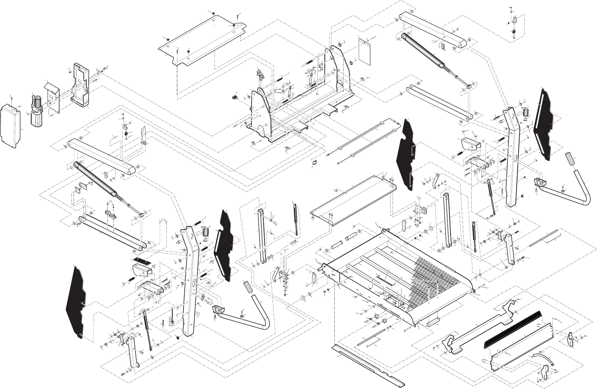
Page 14
Exploded View
150
53
114
111
109
104
113
53
53
53
50
116
53
53
109
111
41
180
140
153
77
6
91
76
79
113
53
53
50
116
118
180
126
91 151
79
33
41
76
162
72
140
153
85
77
102
118
115
115
115
85
126
79
33
155
89
102
149
107
112
104
113
101
9
112
31
31
52
52
52
40
52
52
52
174
134
134
52
52
114 52
52
49
134
52
52
94
117
117
74
21
62
106
74 106
27
28
18
180
180
43
27
100
17
140
28
17
100
18
74
106
176
27
28
58
58
180
140
180
118
78
21
17
17
42
27
28
78
134
78
21
113
79
139
139
105
149
149
103
103
105
7
74
106
94 117
117 162
145
120
14
125
123
122
36
136
16
175
76
5
66
119 75
132
132
136
131
30
127
135
66
144
161
160
159
157
156 157
158 19
169
168
61
59
99
20
80
129
144
161
160
159
157 156 157
158
154
110
68
98
97
124
130
60
91
91
152
91
152
87
86
91
90
170
94
89
177
119
19
66
76
75
93
94
45
45
148
148
148
141
85
88
57
57
60
148
60
147 22
60
82
159
160
161
84
81
74
30
163
178
74
106
106
27
28
27
28
27
28
74
106
67
146
92
67
110
96
44
47
92
164
73
61
59
20
130
99
91
91
93
80
84
152
91
152
86
87
91
88
90
170
94
68
54
70
55
67
98
60
60
60
60
141
82
81
74 106
74
167
63
106
74 106
27
28
30
163
148
27
28
27
28
94
95
67
96
71
71
85
118
8
101
25
166
32
4
65
175
69
30
182
135
66
121
15
145
165
172 13
13
137
66
20
173
142
143
171
72 133
46
48
48
147
1
78
134
NCL917-03-001.ai
56
57
2
29
33
38
34
35
10
26
112
23
24
3
33
29
52
52
52
52
51
108
37
32
39
83
36
64
12
98
167
63
148
98 179
98
98
179
149
107
20
72
142
143
20
128
128
182
30
131
136
20
20
11
181
181
136
36
137
30
175
20
137
165
175
138
65
129
159
160 161
137
22

Over 300 Braun
Dealers Worldwide
"Providing Access to the World"
®
"Providing Access to the World"
International Corporate Hdqrs: P.O. Box 310 Winamac, IN 46996 USA
1-800-THE LIFT (574) 946-6153 FAX: (574) 946-4670
®

Public Use
Wheelchair Lifts
Patent #5,261,779
Patent #6,065,924
Patent #6,238,169
Patent #5,261,779
Patent #6,065,924
Patent #6,238,169
Patent #6,464,447
Patent #6,599,079
Patent #6,692,217
Patent #6,464,447
Patent #6,599,079
Patent #6,692,217
Patent #6,739,824
Patents Pending
© The Braun Corporation
Patent #6,739,824
Patents Pending
© The Braun Corporation
All illustrations, descriptions and specifications in this manual are based on the latest product information available at the
time of publication. The Braun Corporation reserves the right to make changes at any time without notice.
All illustrations, descriptions and specifications in this manual are based on the latest product information available at the
time of publication. The Braun Corporation reserves the right to make changes at any time without notice.
When processing any warranty claims (parts, repairs, etc.), all requests must be processed through The
Braun Corporation Product Support Department. Call 1-800-THE LIFT® (extension 3009) during normal
working hours. Product Support will issue a Return Material Authorization (RMA) number and detail the
procedures required for processing returns and/or authorizing credit.
The lift identification information is provided on the Braun Serial No./Series No. identification tag and
the two warranty cards (shown on inside front cover). The lift identification information must be
provided when filing a warranty claim or ordering parts.
Return Authorization Procedure
32221
January 2006
32221
January 2006
Service Manual for: 03
Series 03
The Braun Corporation of Winamac, Indiana, warrants its wheelchair lift against defects
in material and workmanship for up to five years*, providing the lift is installed, operated and
maintained properly and in conformity with this manual. This warranty is limited to the original
purchaser and does not cover defects in the motor vehicle on which it is installed, or defects in the
lift caused by a defect in any part of the motor vehicle.
This warranty commences on the date the lift is put into service, providing the warranty
registration card is completed and received by The Braun Corporation within twenty days of
purchase. If no warranty card is received, the warranty will expire three years from the date of
manufacture as identified on the lift serial number tag.
This warranty also covers the cost of labor for the repair or replacement of parts for
three years when performed by an approved Braun Dealer. (A labor schedule determines cost
allowance for repairs, which can be provided upon request by an approved Braun Dealer).
This warranty does not cover normal maintenance, service, or periodic adjustments
necessitated by use or wear. The Braun Corporation will not, under any circumstances, pay for
loss of use, incidental or consequential damages related to the lift, or vehicle in which it is installed.
This warranty will become null and void if the lift has been damaged through accident,
misuse, or neglect, or if the lift has been altered in any respect.
* The five-year portion of this warranty covers the following lift’s power train parts:
• Cable • Cylinder • Flow Control • Gear Box • Motor • Pump • Hydraulic Hose & Fittings
• Solid State Controller
All remaining lift components are covered by a three-year warranty.
Century Series Lift
Braun “Worry-Free”
Five-Year Limited Warranty
"Providing Access to the World"
International Corporate Hdqrs: P.O. Box 310 Winamac, IN 46996 USA
1-800-THE LIFT® (574) 946-6153 FAX: (574) 946-4670
®
®
Braun NCL Series
Braun NCL Series
Century
HZg^Zh
HZg^Zh
C8A
C8A
