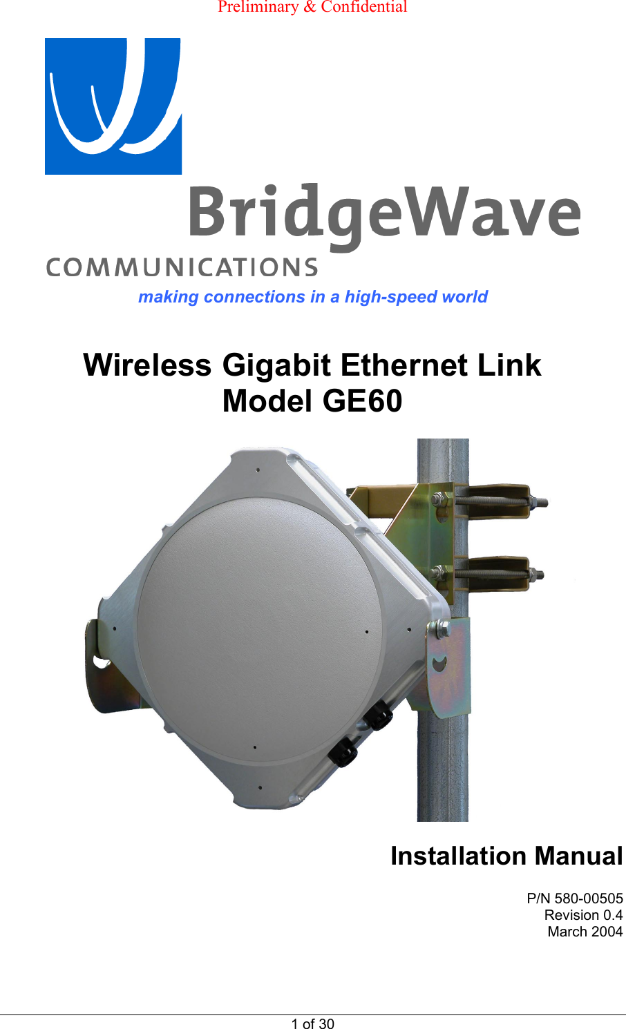
BridgeWave Communications GE60 Wireless Gigabit Ethernet Link User Manual Installation Operation Manual
BridgeWave Communications, Inc. Wireless Gigabit Ethernet Link Installation Operation Manual
Contents
- 1. User Manual
- 2. User Manual 1 of 2
- 3. User Manual 2 of 2
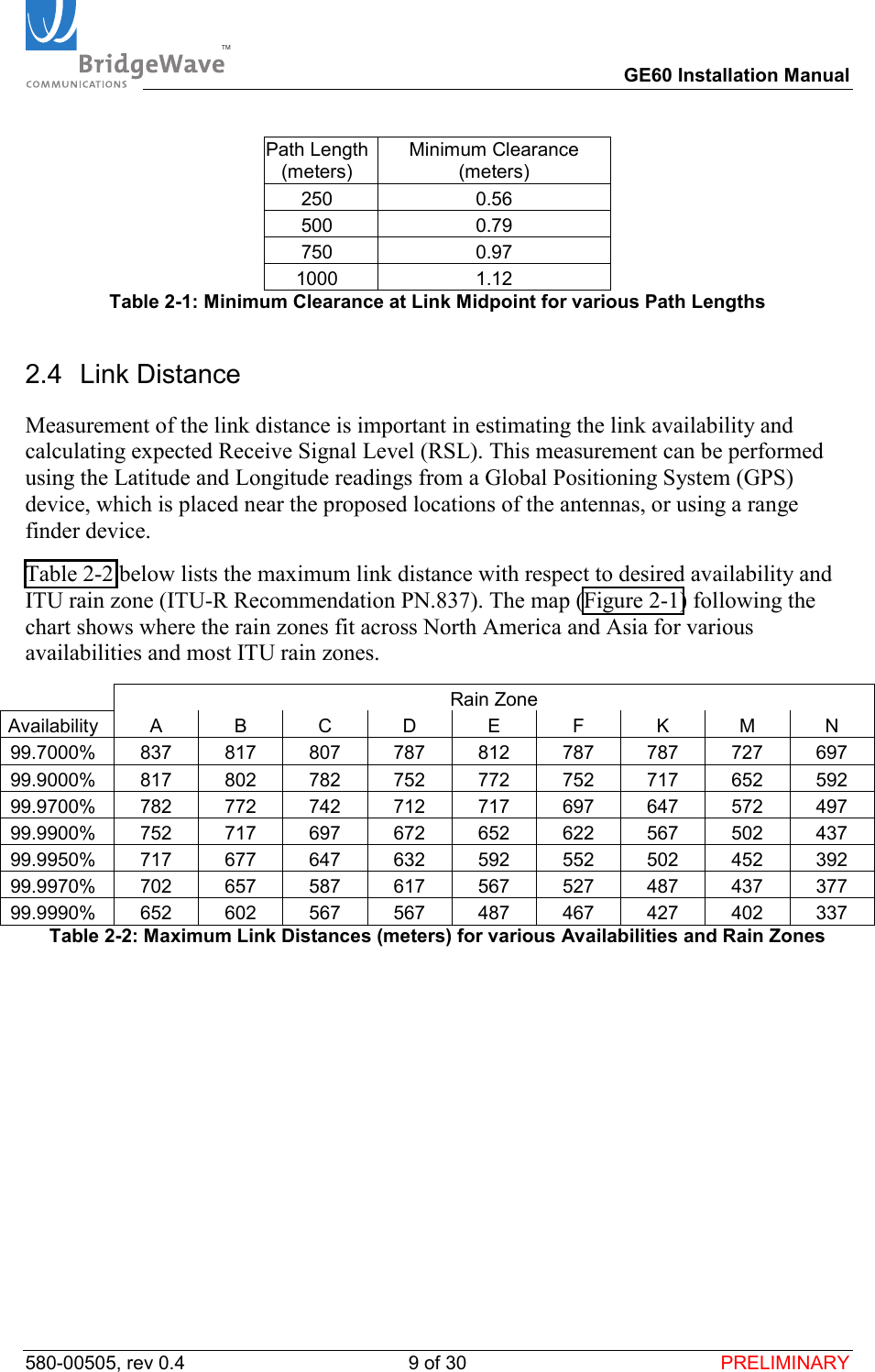
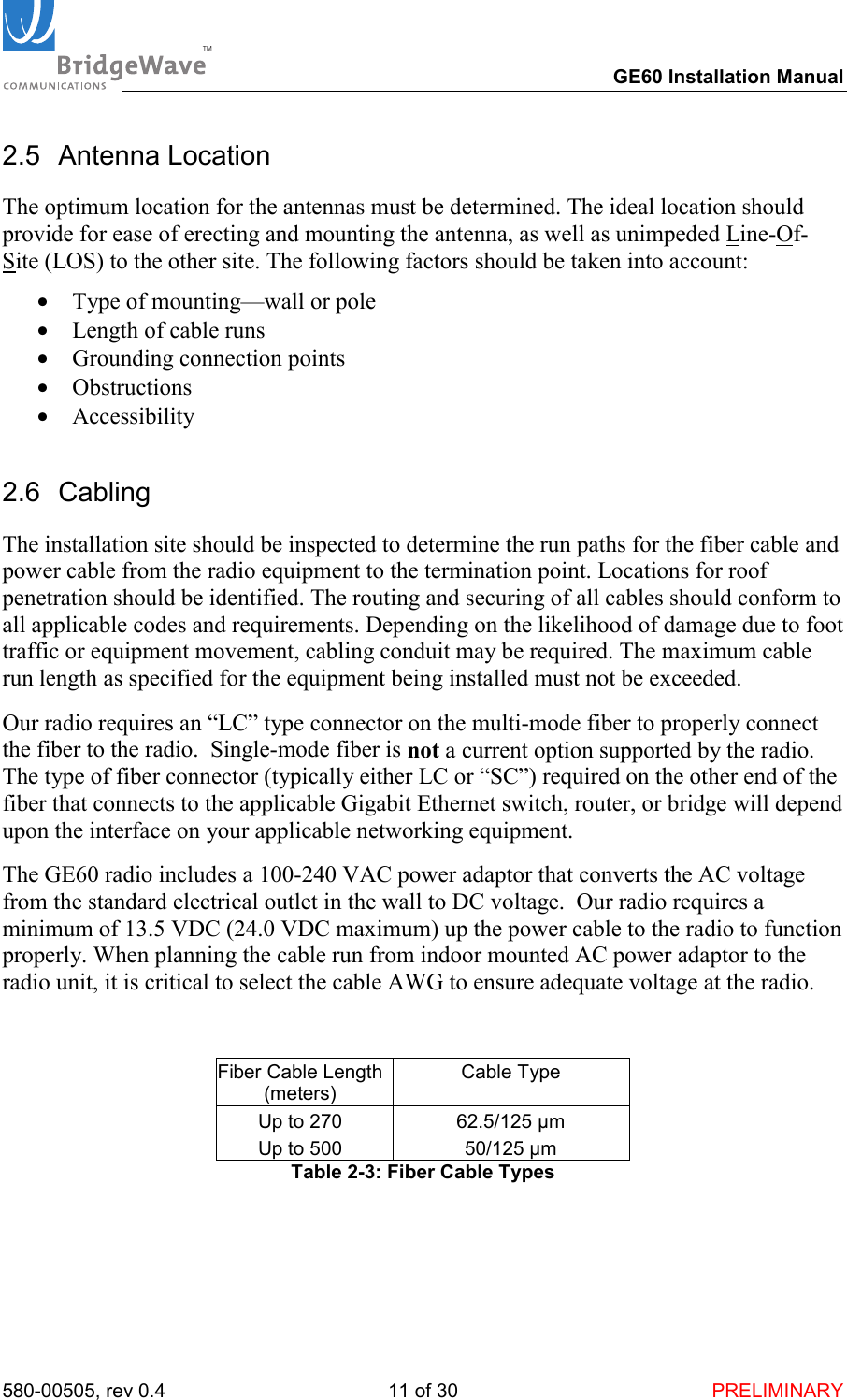
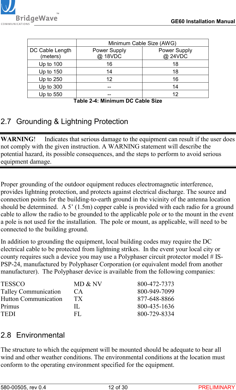
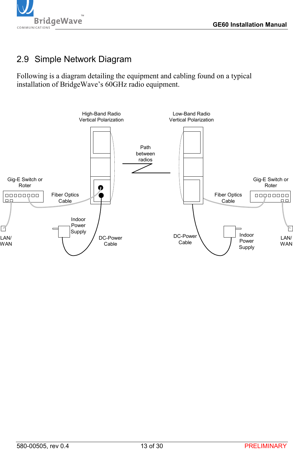
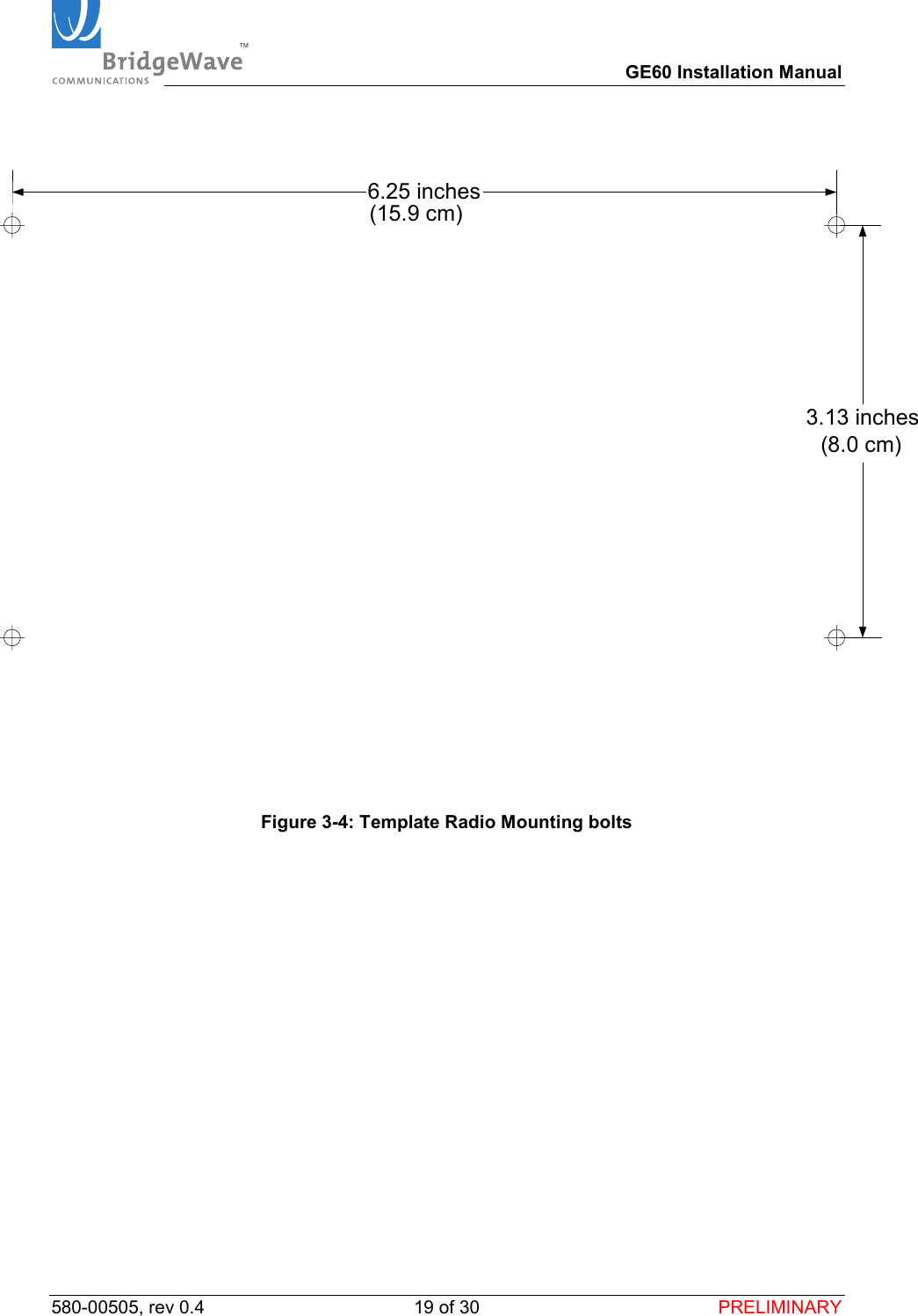
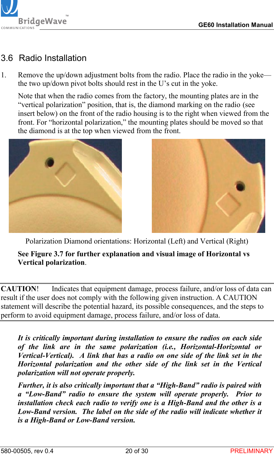
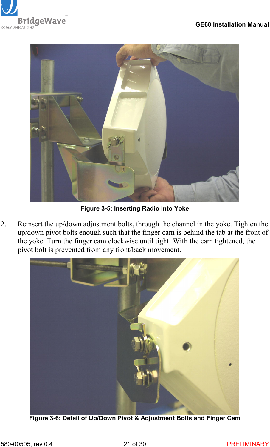
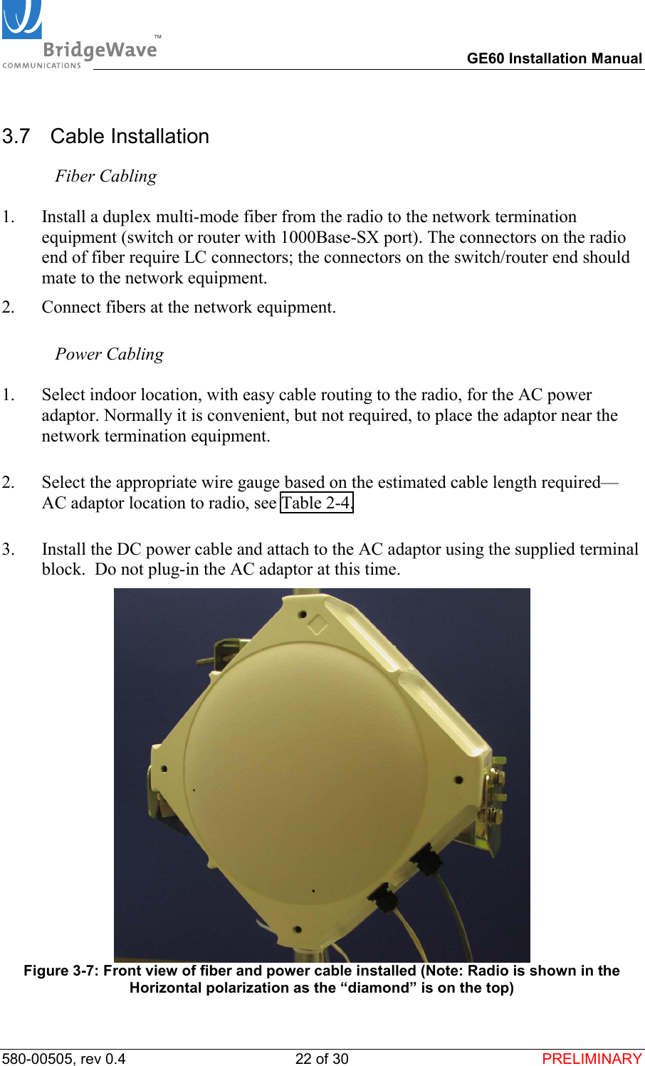
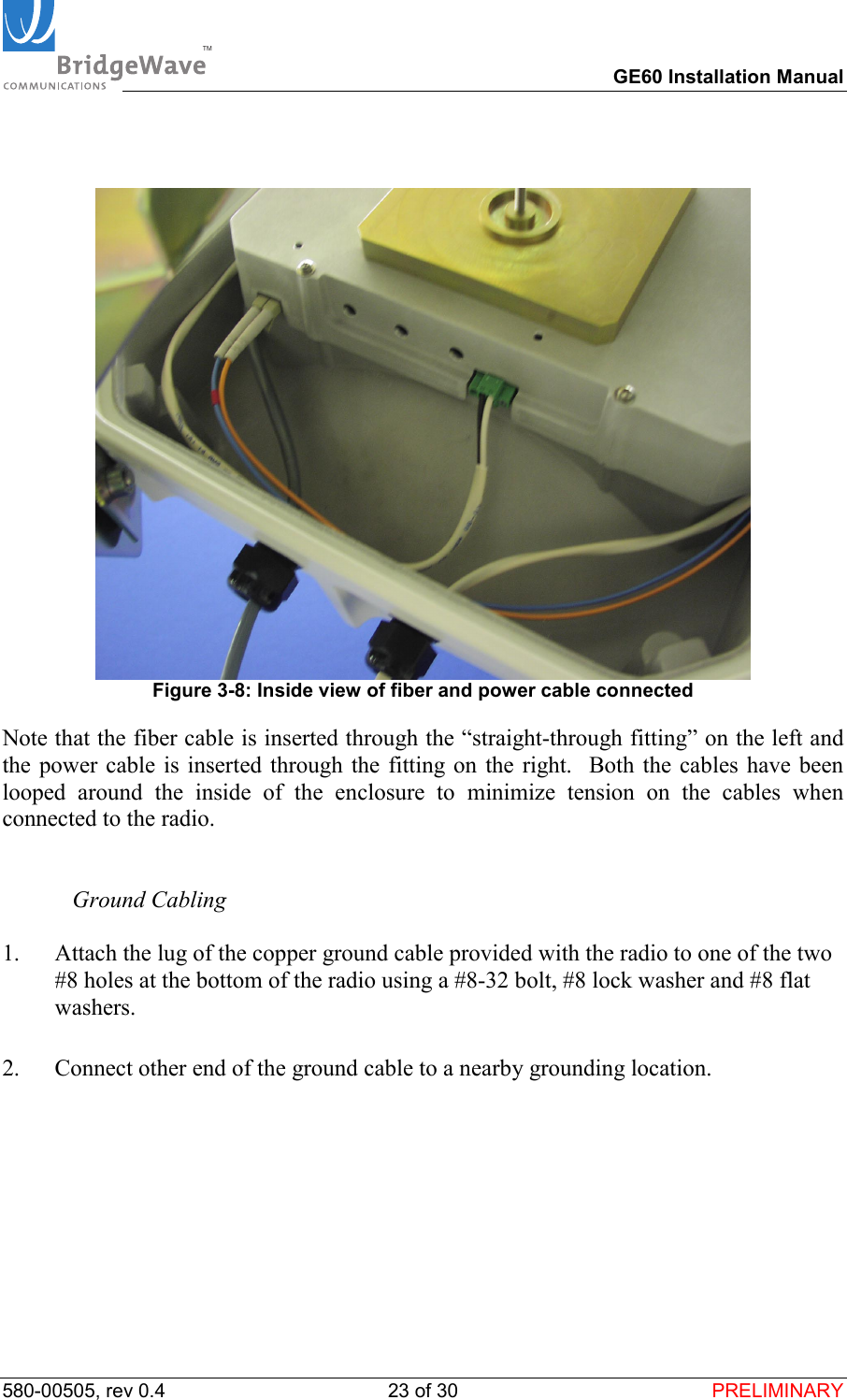
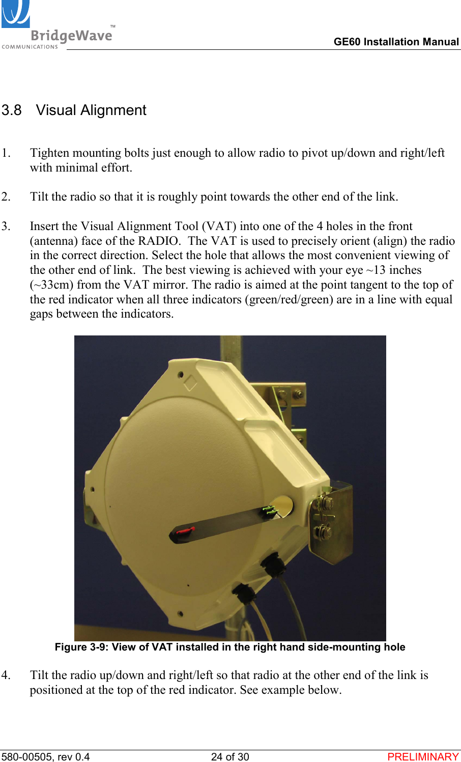
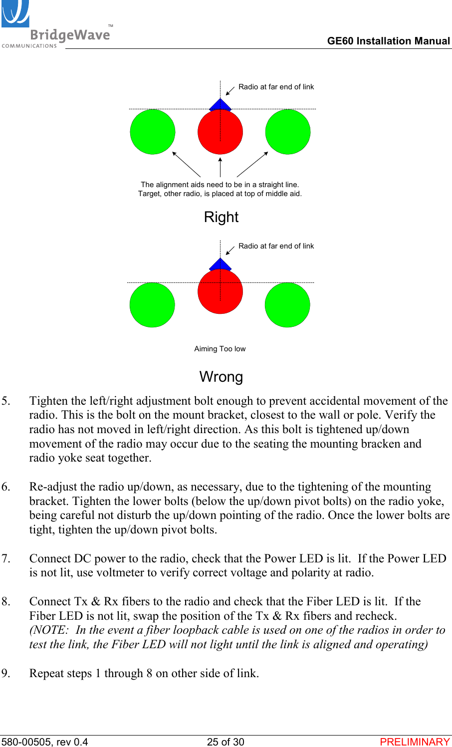
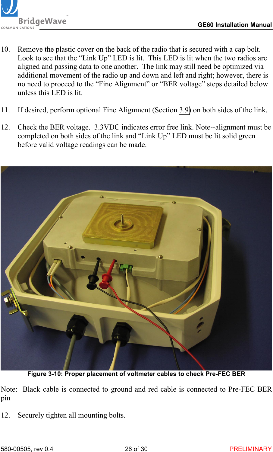
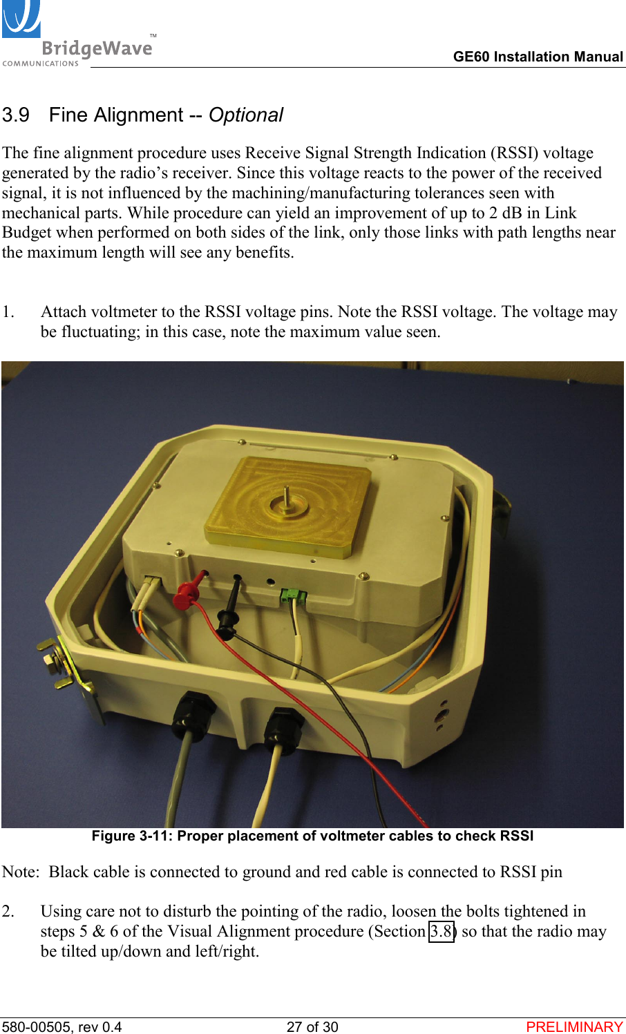
User Manual