BridgeWave Communications GE60 Microwave Link User Manual Installation Operation Manual
BridgeWave Communications, Inc. Microwave Link Installation Operation Manual
Contents
- 1. User Manual
- 2. User Manual 1 of 2
- 3. User Manual 2 of 2
User Manual 2 of 2

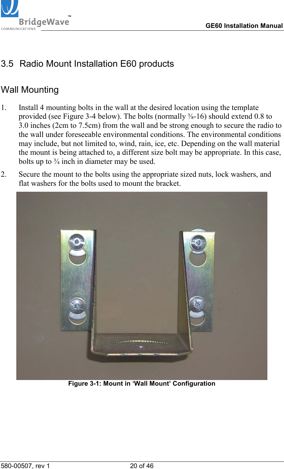
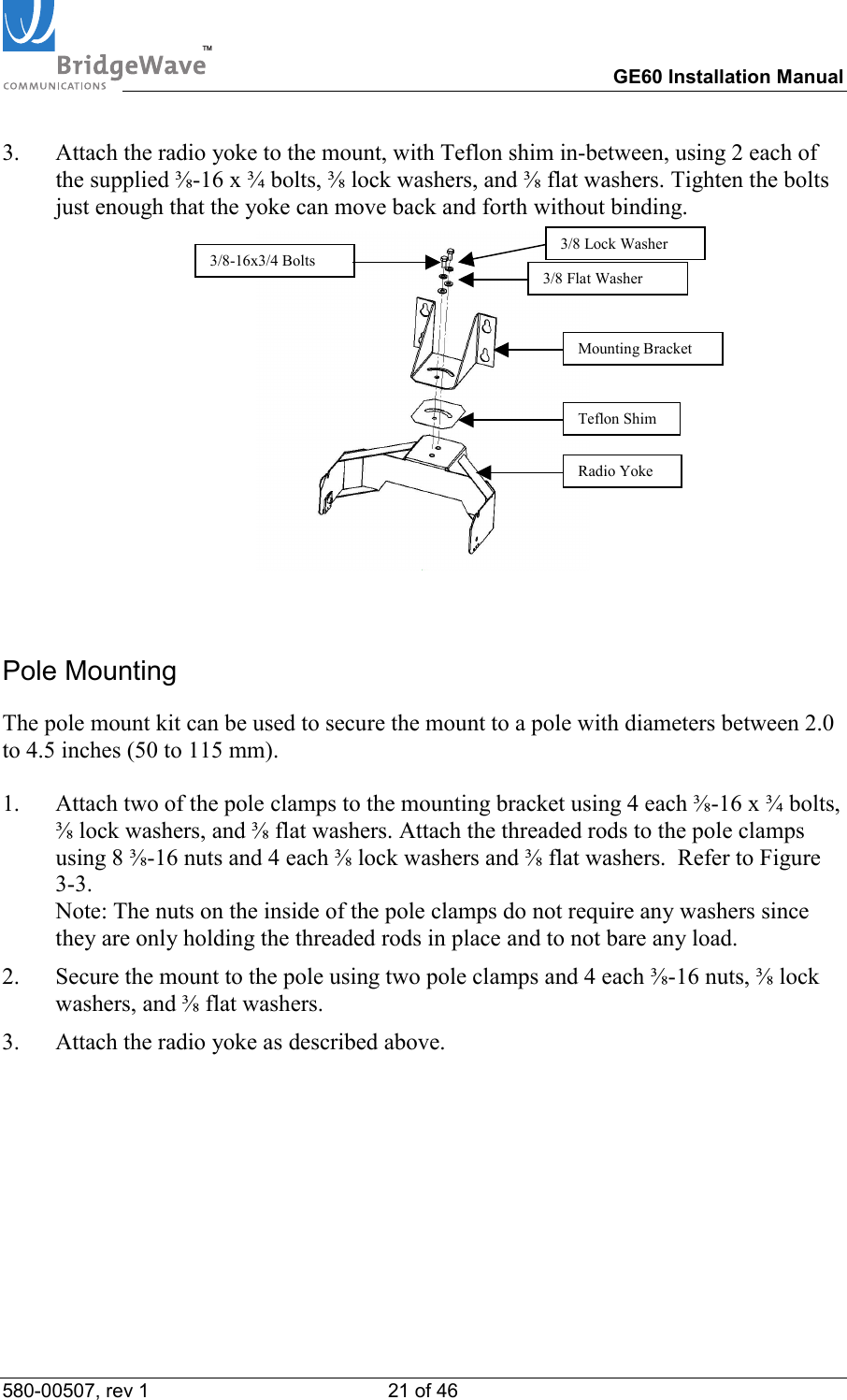

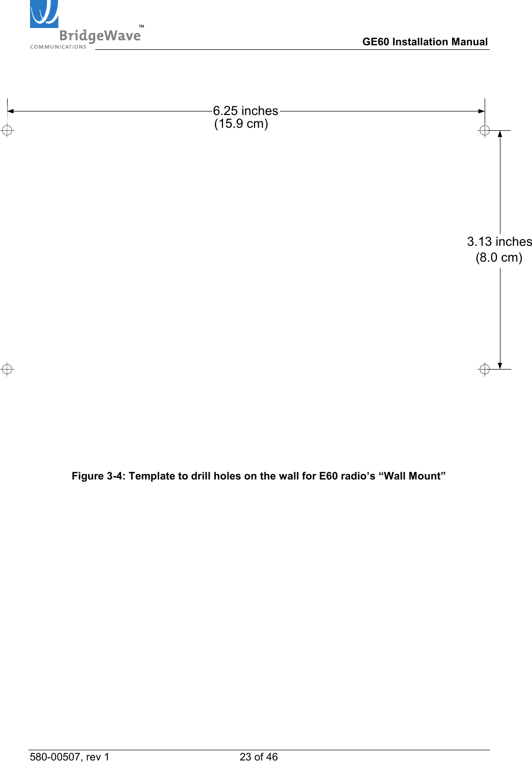
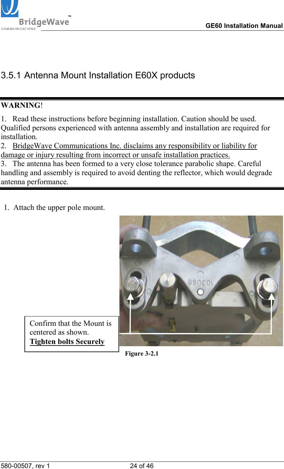
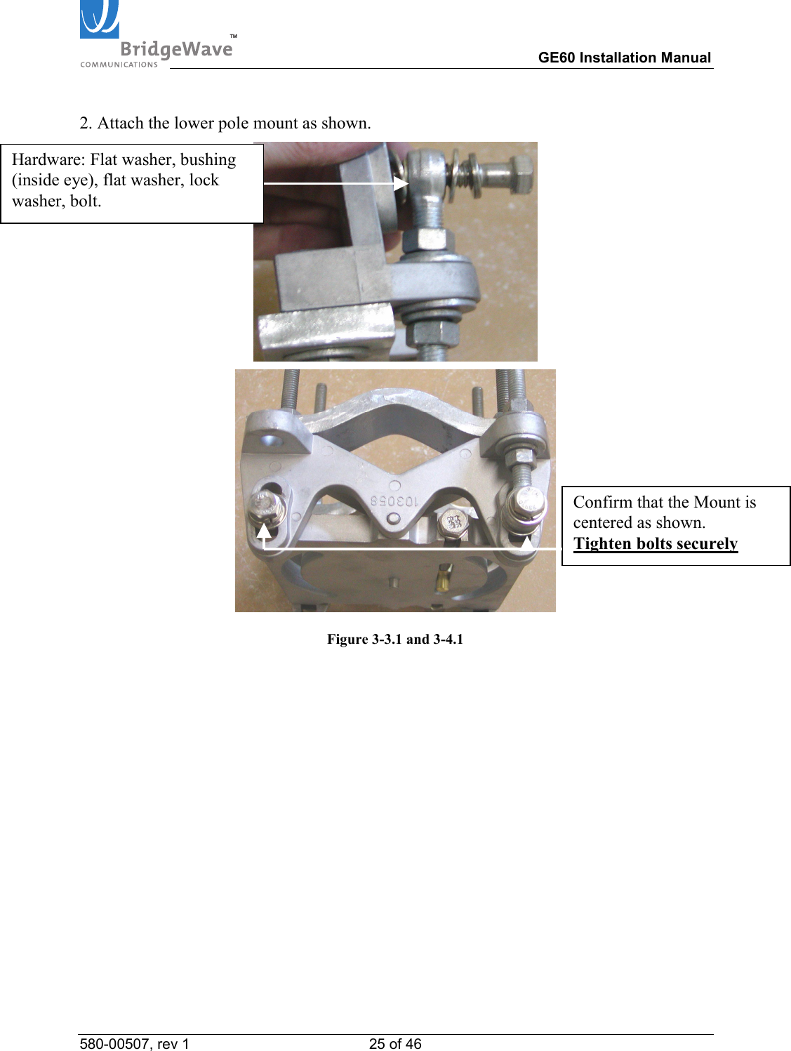
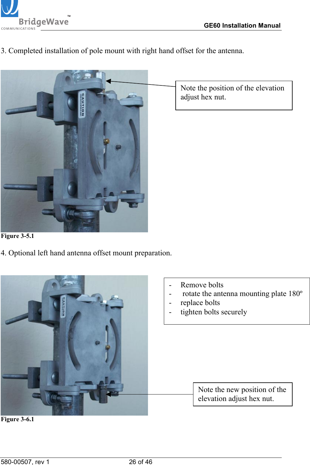
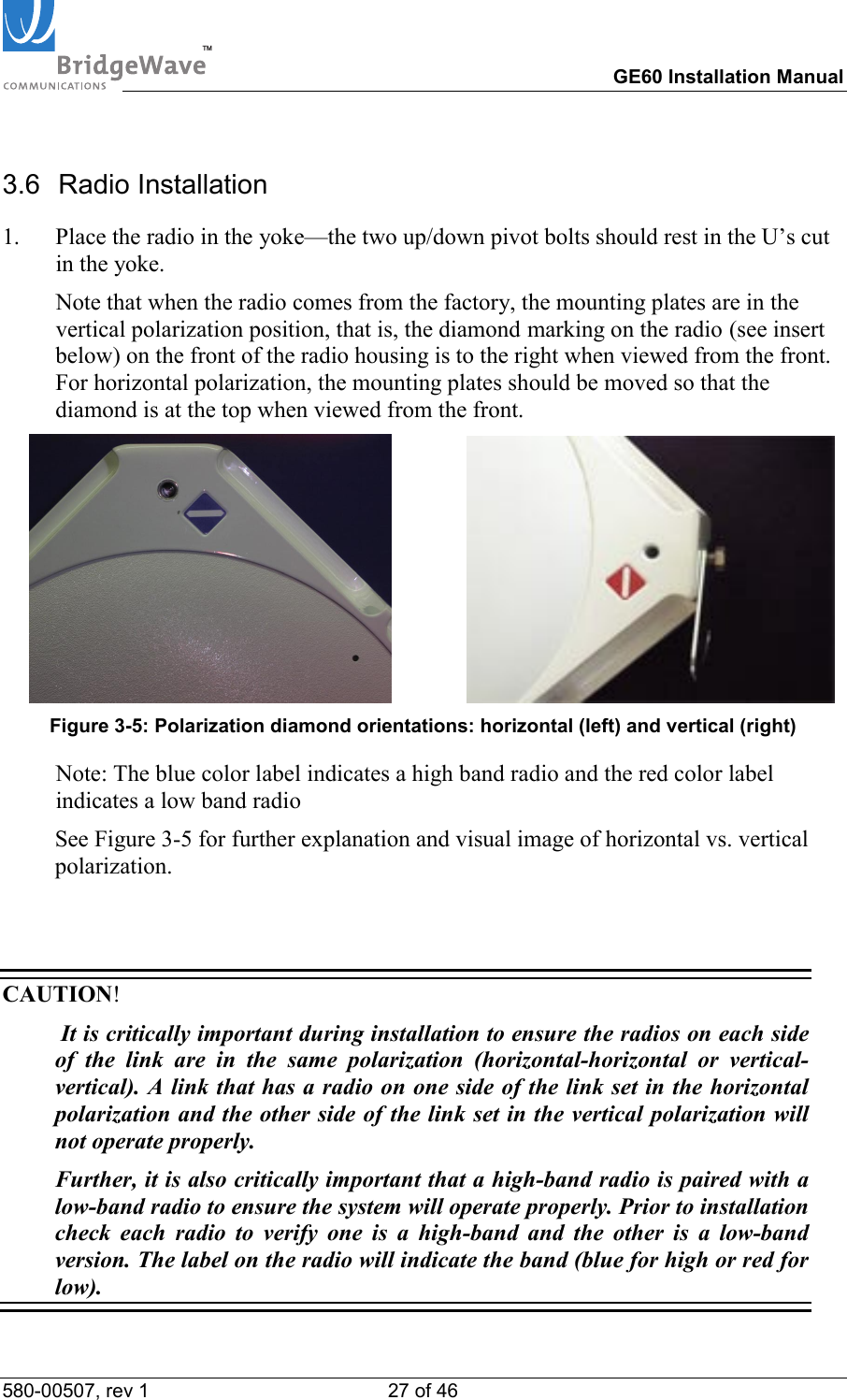

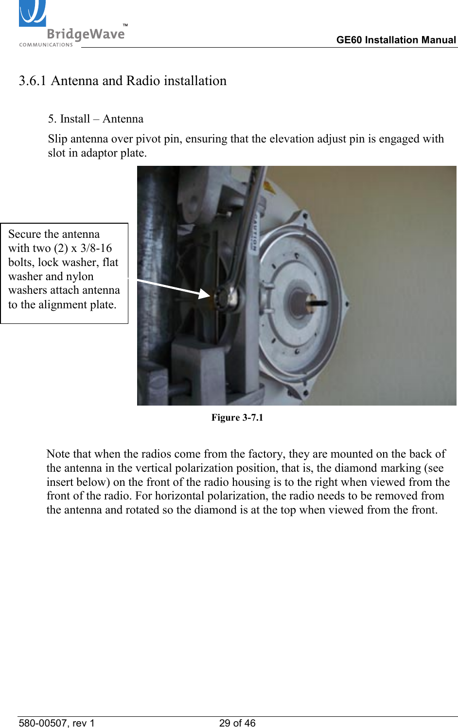
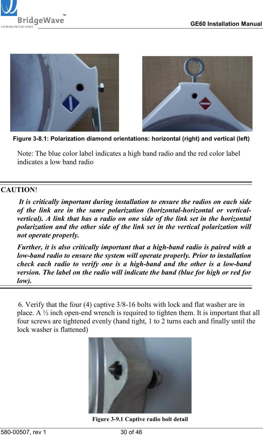
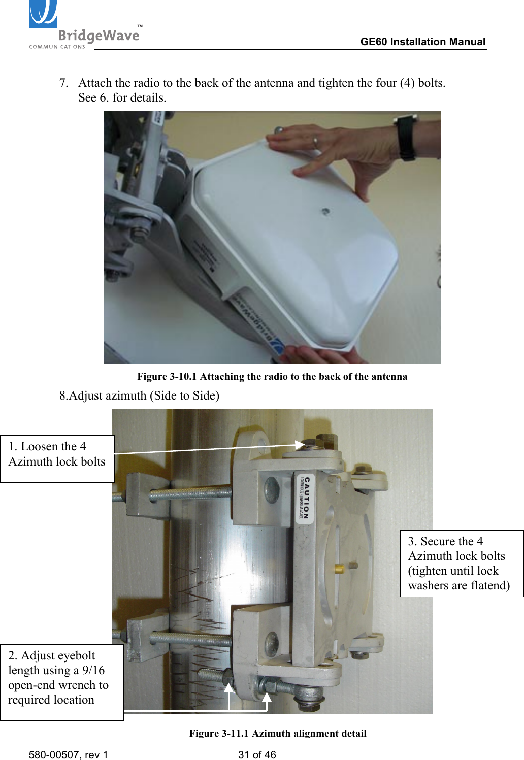
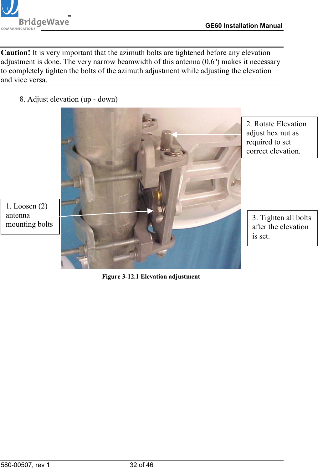

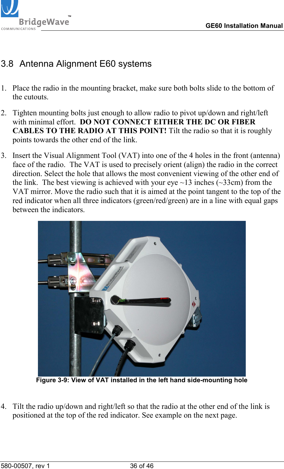
![TM GE60 Installation Manual 580-00507, rev 1 37 of 46 Radio at far end of linkThe alignment aids need to be in a straight line.Target, other radio, is placed at top of middle aid.Right Radio at far end of linkAiming Too lowWrong 5. Ensure fiber cables are still disconnected! 6. Connect DC power to the radio. 7. Verify that the Power LED is lit. If the Power LED is not lit, use voltmeter to verify correct voltage and polarity at radio. To reverse the power polarity, unplug the power jack and swap the crimp connectors for the two conductors. 8. Repeat steps 1 through 7 on other side of the link. 9. Verify Link Up LED’s are lit on both radios. 10. Slightly rotate each radio up/down and left/right to find the maximum RSL voltage reading. [If it was not possible to use the VAT to visually align the radios, then the radios must be rotated at least ten degrees on each side of the visually-perceived alignment center to ensure that the true maximum RSL voltage is found; note that the width of the center beam is only 1.4 degrees and the first side-lobe beam is only 2.5 degrees off from center.] Set the radio in the position that results in the highest RSL voltage reading. See Section 3.9 to determine the proper use of the supplied test cable in order to read the RSL voltage. Note: Verify that the RSL voltage falls within the expected range based on the graph in Appendix A.](https://usermanual.wiki/BridgeWave-Communications/GE60.User-Manual-2-of-2/User-Guide-568966-Page-22.png)