Bright Star Engineering WCB33 Automotive Diagnostic Tool Cable User Manual wiTECHUserGuide 03 11 11
Bright Star Engineering, Inc. Automotive Diagnostic Tool Cable wiTECHUserGuide 03 11 11
UserManual.wiki
>
Bright Star Engineering
>
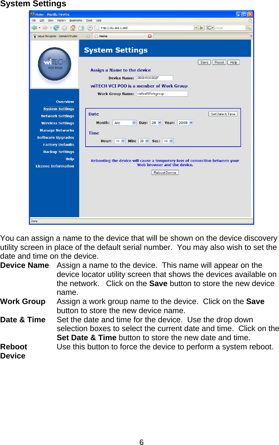
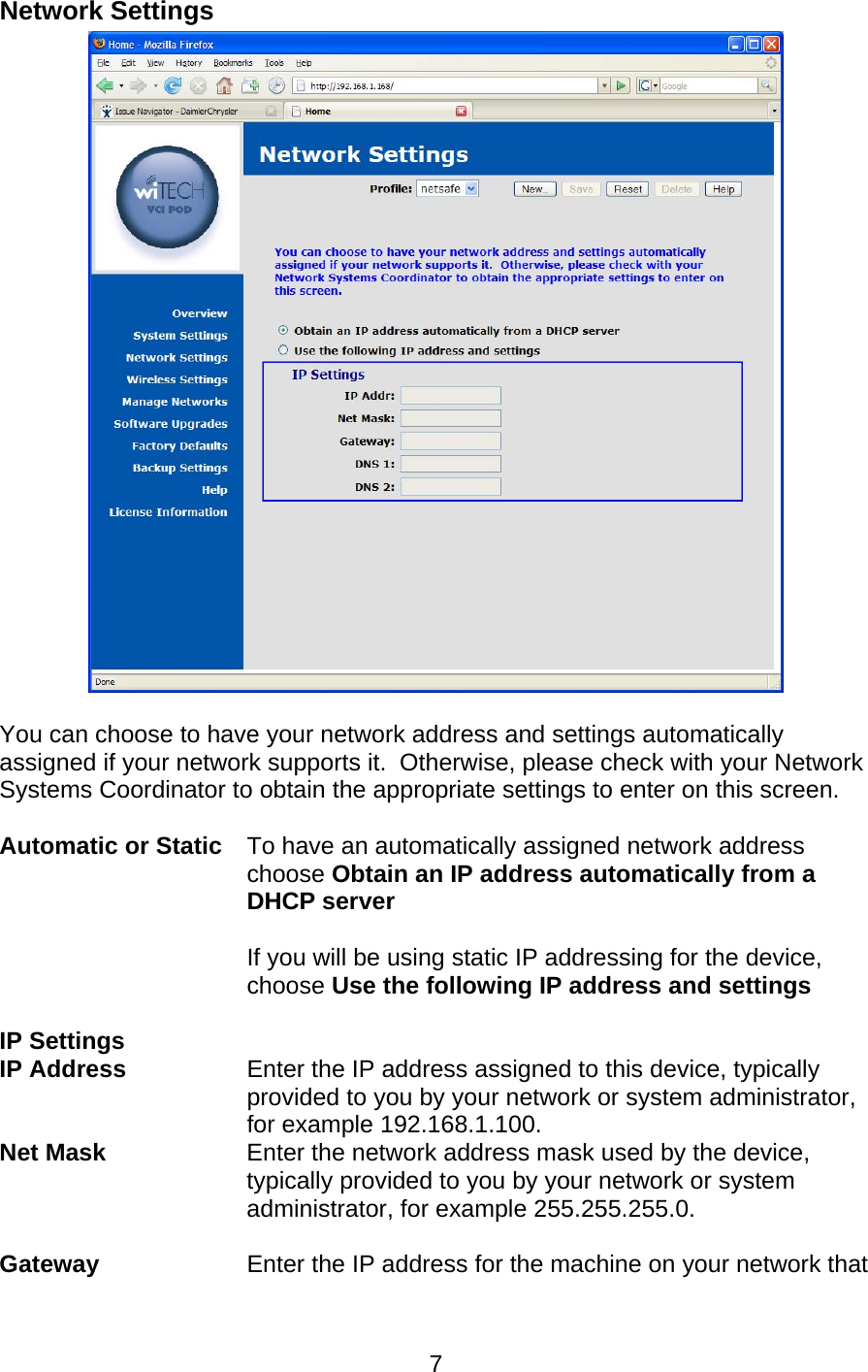
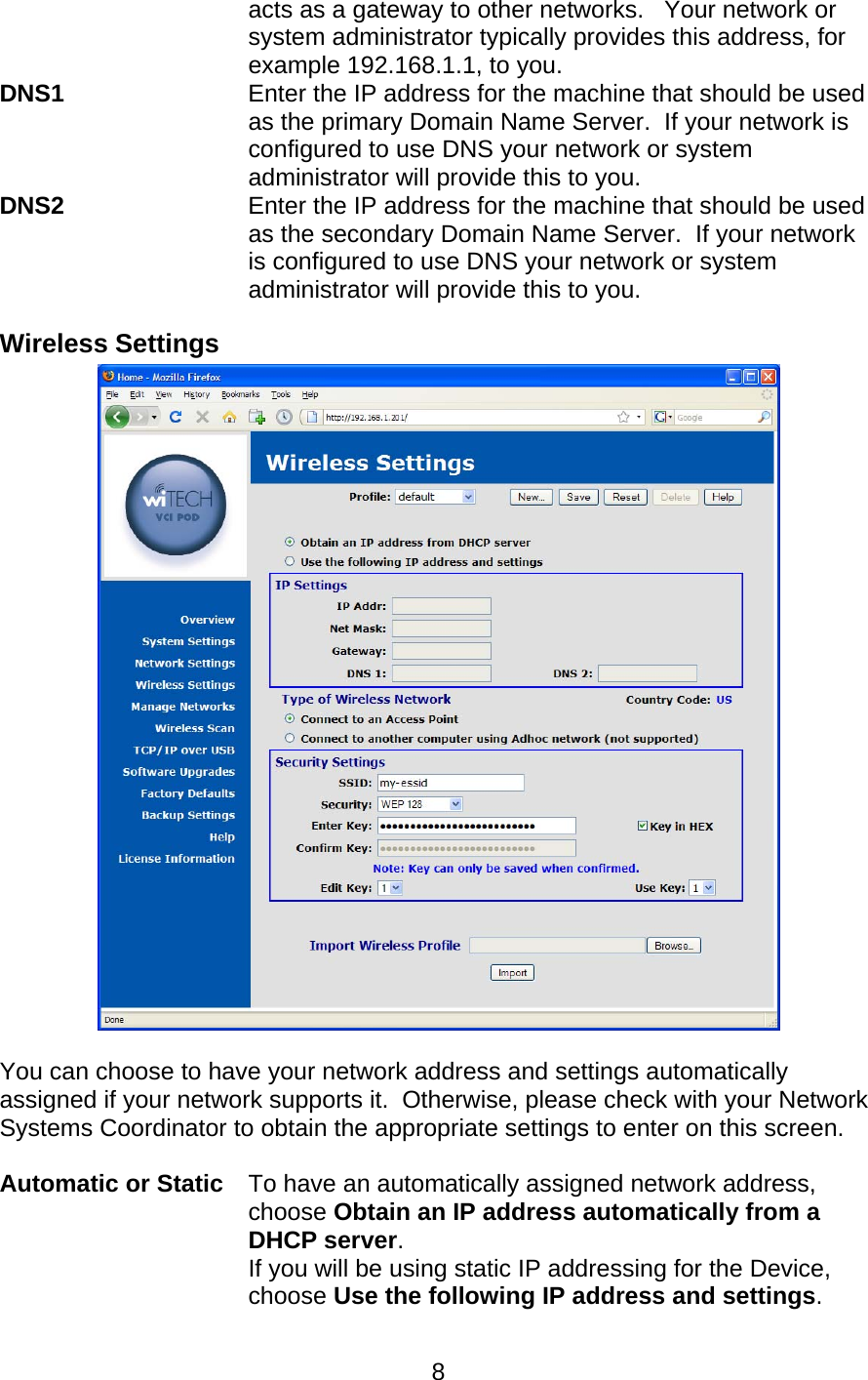
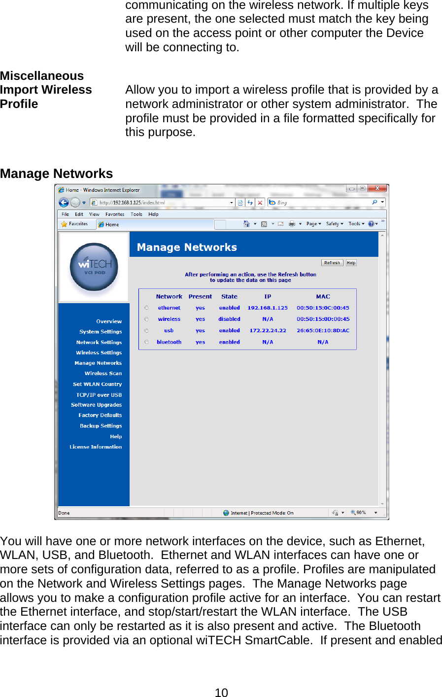
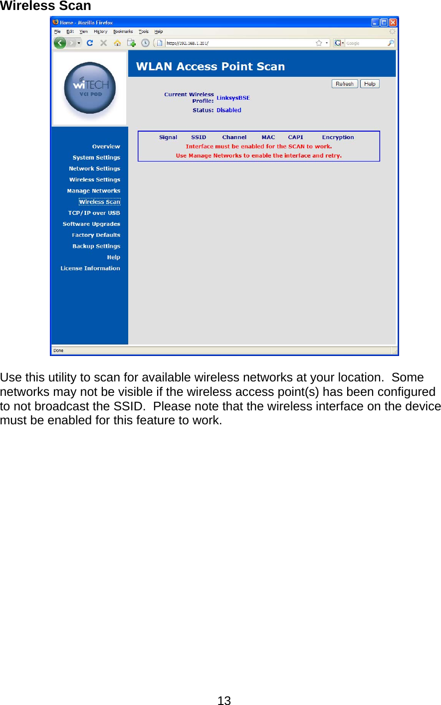
WCB33 User Manual
User Manual
Navigation menu
Upload a User Manual
Namespaces
Wiki Guide
HTML
PDF
Info
Views
User Manual
Discussion / Help
Navigation