Bright Star Engineering WCB33 Automotive Diagnostic Tool Cable User Manual wiTECHUserGuide 03 11 11
Bright Star Engineering, Inc. Automotive Diagnostic Tool Cable wiTECHUserGuide 03 11 11
User Manual

i
wiTECH VCI POD
User Guide
Bright Star Engineering
299 Ballardvale Street, Suite 5
Wilmington, MA 01887
Tel: (978) 642-3200
Fax: (978) 642-3199
www.brightstareng.com

ii
FCC Regulatory statements
This equipment has been tested and found to comply with the limits for a Class B digital device,
pursuant to Part 15 of the FCC rules. These limits are designed to provide reasonable protection
against harmful interference in a residential installation. This equipment generates, uses and can
radiate radio frequency energy and, if not installed and used in accordance with the instructions,
may cause harmful interference to radio communications. However, there is no guarantee that
interference will not occur in a particular installation. If this equipment does cause harmful
interference to radio or television reception, which can be determined by turning the equipment
off and on, the user is encouraged to try to correct the interference by one or more of the
following measures:
1. Reorient or relocate the receiving antenna.
2. Increase the separation between the equipment and receiver.
3. Connect the equipment to an outlet on a circuit different from that to which the receiver is
connected.
4. Consult the dealer or an experienced radio/TV technician.
This device complies with Part 15 of the FCC Rules.
Operation is subject to the following two conditions:
1. This device may not cause harmful interference
2. This device must accept any interference received, including interference that may cause
undesired operation.
FCC Warning
Modifications not expressly approved by the manufacturer could void the user’s
authority to operate the equipment under FCC Rules.
Radio Frequency Exposure
This equipment has been evaluated in accordance with the FCC bulletin 56 “Hazards of radio
frequency and electromagnetic fields” and bulletin 65 “ Human exposure to radio frequency and
electromagnetic fields. Safe operation in an uncontrolled environment will result if the following
distances from the device are maintained as a minimum. A distance greater than or equal to 20
cm from the device should be maintained.
Industry Canada
This digital apparatus does not exceed the Class B limits for radio noise emissions from digital
apparatus as set out in the interference- causing equipment standard entitled “Digital Apparatus,”
ICES-003 of the Department of Communications.
Cet appareil numérique respecte les limites de bruits radioélectriques applicables
aux appareils numériques de Classe B prescrites dans la norme sur le matériel
brouilleur: “Appareils Numériques,” NMB-003 édictée par le ministère des
Communications.
This device complies with RSS 210 of Industry Canada.
Operation is subject to the following two conditions: (1) this device may not cause
interference, and (2) this device must accept any interference, including
interference that may cause undesired operation of this device.”
L ‘ utilisation de ce dispositif est autorisée seulement aux conditions suivantes :
(1) il ne doit pas produire de brouillage et (2) l’ utilisateur du dispositif doit étre
prêt à accepter tout brouillage radioélectrique reçu, même si ce brouillage est
susceptible de compromettre le fonctionnement du dispositif.
iii
Notice
The information in this document is subject to change without notice.
THE SOFTWARE AND DOCUMENTATION ARE PROVIDED "AS IS" WITHOUT
WARRANTY OF ANY KIND INCLUDING WITHOUT LIMITATION, ANY
WARRANTY OF MERCHANTABILITY OR FITNESS FOR A PARTICULAR
PURPOSE. FURTHER, Bright Star Engineering DOES NOT, GUARANTEE, OR
MAKE ANY REPRESENTATIONS REGARDING USE, OR THE RESULTS OF
THE USE, OF THE SOFTWARE OR WRITTEN MATERIAL IN TERMS OF
CORRECTNESS, ACCURACY, RELIABILITY, OR OTHERWISE.
Restricted Rights Legend
Use, duplication, or disclosure by the United States Government is subject to
restrictions as set forth in subparagraph (c)(1)(ii) of the Rights in Technical Data
and Computer Software clause at DFARS 252.227-7013.
This document may not, in whole or in part, be copied, reproduced, translated, or
reduced to any electronic medium or machine-readable form without prior
consent, in writing, from Bright Star Engineering, Inc.
Copyright © 2008 Bright Star Engineering, Inc.
All Rights Reserved
Printed in the USA
iv
Table of Contents
Revision History .................................................................................................... 1
Getting Started with the Device ............................................................................ 2
Setting Up and Powering On ............................................................................. 2
Connecting to the Network ................................................................................ 2
LAN with DHCP ............................................................................................. 2
LAN with Static IP Addressing ....................................................................... 2
Device Discovery Mechanism ........................................................................... 2
Device Overview ................................................................................................... 3
LEDs ................................................................................................................. 3
Reset Button...................................................................................................... 4
Configuring Device and Network Settings ............................................................. 5
Using the HTTP Interface .................................................................................. 5
System Settings ............................................................................................. 6
Network Settings ............................................................................................ 7
Wireless Settings ........................................................................................... 8
Manage Networks ........................................................................................ 10
Wireless Scan .............................................................................................. 13
TCP/IP over USB ......................................................................................... 14
Factory Defaults ........................................................................................... 15
Backup Settings ........................................................................................... 16
Software .............................................................................................................. 17
Software Upgrades .......................................................................................... 17
Using the HTTP Installer .............................................................................. 17
Recovering from a Failed Upgrade .............................................................. 18
Installing Applications ...................................................................................... 18
1
Revision History
Revision Date Description
1.0 July 28, 2008 Initial release of platform documentation
1.1 December 9, 2008 Update to reflect changes in software
functionality.
1.2
1.3
February 22, 2011
March 11,2011
Update to add information on Bluetooth
networking capability
Added FCC and IC Statements

2
Getting Started with the Device
Setting Up and Powering On
Attach the DC power supply to the device. Verify the green PWR LED is on. As
soon as power is supplied to the device it will begin a boot sequence. The BUSY
LED will be on during the boot phase. Once the device is booted into normal
operational mode the PWR LED will be on and all other LEDs will remain off.
Connecting to the Network
Connect an Ethernet cable to the device. You can connect the other end of the
Ethernet cable to a computer or network device such as a switch or router
depending on your local area network configuration (see below).
LAN with DHCP
The default TCP/IP settings for the Ethernet network interface will use DHCP to
obtain an IP Address, subnet mask, gateway, and DNS information. If your local
area network supports this configuration, connect the Ethernet cable to a switch,
hub, or router on your LAN.
LAN with Static IP Addressing
If the device requires a static IP Address to communicate with other nodes on
your local area network you will first have to connect the Ethernet cable to
another computer running software that supports ZCIP. The device is equipped
to use a ZCIP address when DHCP is not available. An address of
169.254.253.252 is used if possible; otherwise a random ZCIP address is
assigned.
Device Discovery Mechanism
The Service Location Protocol (SLP) is supported for device discovery.
If you do not have a copy of the Bright Star Engineering device locator utility,
dFind, use a web browser to download the utility from:
http://www.brightstareng.com/support/dfind.html.
Start dFind on a computer connected to the same network as the device. dFind
uses the SLP protocol to locate devices advertising as a service. The IP address
and serial number for the device will be shown on the dFind screen. Double click
with your mouse on the line for the device you wish to connect to. The device
configuration web site will appear.
3
Device Overview
LEDs
The device has five (5) LEDs on an end panel. Moving from left to right the LEDs
are described below.
PWR Power LED indicates the device has power from a vehicle source
and/or an DC adapter
SAFE This LED will be turned on whenever the device enters a mode of
operation where a known good network configuration is used. The
default SAFE configuration uses DHCP to acquire a TCP/IP address.
This LED is also used to indicate a Bluetooth enabled wiTECH
SmartCable is connected to the device and is ready for a network
connection.
BUSY Busy LED will be on during system boot. During normal device
operation this LED is not used, remains off, and is available to
applications that wish to show the device is processing data, for
example vehicle traffic or application data crunching. When the
device boots into Recovery Mode, this LED will blink rapidly in unison
with the WLAN LED.
WLAN This led will be on when the WLAN is being used and blink to indicate
network traffic across the interface. As noted this LED will blink
rapidly when the device boots into Recovery Mode. The WLAN led is
also used to show traffic is moving across the Bluetooth network link
when a wiTECH SmartCable is being used and the SAFE led is on.
REC This is an application specific LED, not used directly by the device
system software,
Note: The SAFE, BUSY, WLAN, and REC LEDs will blink in an alternating
pattern when a hardware or software error is detected when the device is first
powered on. When this error state occurs the device may operate in an
unspecified or incorrect manner. When the device is in this state the SAFE and
REC LEDs will blink on while WLAN and BUSY are off, then SAFE and REC
LEDs will be off while WLAN and BUSY blink on. This can be characterized as a
railroad-crossing pattern.
If this problem should occur, attempt a reboot of the device by removing and then
re-attaching the power source. If the problem persists you should contact
Customer Support for assistance.
If an error should occur during an upgrade of the system software, all four LEDs,
SAFE, BUSY, WLAN, and REC, will turn on and remain on until the unit is
powered down. Refer to the Software Upgrades section further on in this
document for more information on this topic.
4
Reset Button
• Recovery Mode: On the front panel is a small opening for the reset
button. This button serves four purposes. First, the button can be
pressed when applying power to force the device into Recovery Mode.
The device will boot into a limited configuration that will allow you to apply
a product software upgrade via the provided web interface. This mode
should be used to re-install the system software in the event the device is
not operating as expected.
• Safe Mode: The second use of the reset button is to put the Ethernet
network interface into a default state. Pressing and holding the reset
button for 5 or more seconds, then releasing it when the device is running
normally will restart the Ethernet network interface with configuration
settings for connecting to a TCP/IP local area network using DHCP. The
subnet mask, gateway, and DNS information is expected to be provided
via the DHCP server. The device can then be located on the network
using dFind, the Bright Star Engineering provided device location utility
(see Device Discovery Mechanism above).
• Data Recording Off: Another use of the reset button is to turn Data
Recorder mode off. When the device is being used to gather vehicle
information via the Data Recorder application, pressing and releasing the
reset button will turn the application off. The device will be returned to
Pass-Through mode.
• Reboot: The final use of the reset button is to force the device to reboot.
Pressing and releasing the reset button, when not held in for more than 3
seconds, will cause the device to reboot the system software.
5
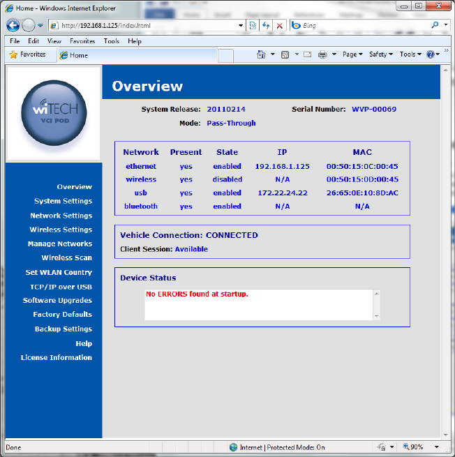
Configuring Device and Network Settings
Using the HTTP Interface
Shown below is the main screen for the device configuration web site. The
Overview page will provide you with version information for the hardware and
software and the device serial number.
6
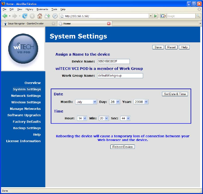
System Settings
You can assign a name to the device that will be shown on the device discovery
utility screen in place of the default serial number. You may also wish to set the
date and time on the device.
Device Name Assign a name to the device. This name will appear on the
device locator utility screen that shows the devices available on
the network. Click on the Save button to store the new device
name.
Work Group Assign a work group name to the device. Click on the Save
button to store the new device name.
Date & Time Set the date and time for the device. Use the drop down
selection boxes to select the current date and time. Click on the
Set Date & Time button to store the new date and time.
Reboot
Device Use this button to force the device to perform a system reboot.
7
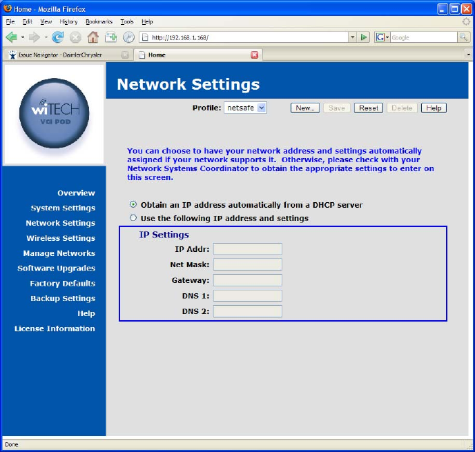
Network Settings
You can choose to have your network address and settings automatically
assigned if your network supports it. Otherwise, please check with your Network
Systems Coordinator to obtain the appropriate settings to enter on this screen.
Automatic or Static To have an automatically assigned network address
choose Obtain an IP address automatically from a
DHCP server
If you will be using static IP addressing for the device,
choose Use the following IP address and settings
IP Settings
IP Address Enter the IP address assigned to this device, typically
provided to you by your network or system administrator,
for example 192.168.1.100.
Net Mask Enter the network address mask used by the device,
typically provided to you by your network or system
administrator, for example 255.255.255.0.
Gateway Enter the IP address for the machine on your network that
8
acts as a gateway to other networks. Your network or
system administrator typically provides this address, for
example 192.168.1.1, to you.
DNS1 Enter the IP address for the machine that should be used
as the primary Domain Name Server. If your network is
configured to use DNS your network or system
administrator will provide this to you.
DNS2 Enter the IP address for the machine that should be used
as the secondary Domain Name Server. If your network
is configured to use DNS your network or system
administrator will provide this to you.
Wireless Settings
You can choose to have your network address and settings automatically
assigned if your network supports it. Otherwise, please check with your Network
Systems Coordinator to obtain the appropriate settings to enter on this screen.
Automatic or Static To have an automatically assigned network address,
choose Obtain an IP address automatically from a
DHCP server.
If you will be using static IP addressing for the Device,
choose Use the following IP address and settings.
9
IP Settings
IP Address Enter the IP address assigned to this Device, typically
provided to you by your network or system administrator,
for example 192.168.1.100.
Net Mask Enter the network address mask used by the Device,
typically provided to you by your network or system
administrator, for example 255.255.255.0.
Gateway Enter the IP address for the machine on your network that
acts as a gateway to other networks. Your network or
system administrator typically provides this address, for
example 192.168.1.1, to you.
DNS1 Enter the IP address for the machine that should be used
as the primary Domain Name Server. If your network is
configured to use DNS your network or system
administrator will provide this to you.
DNS2 Enter the IP address for the machine that should be used
as the secondary Domain Name Server. If your network
is configured to use DNS your network or system
administrator will provide this to you.
Type of Wireless
Network To connect your Device to the network via a wireless
access point, choose Connect to an Access Point.
If you need to connect your Device directly to PC or some
other computer, choose Connect to another computer
using Adhoc network.
Security Settings
SSID Enter the Service Set Identification that should be used by
your Device to join a 802.11 wireless network.
Security Select the encryption technique to be used when
communicating on the wireless network. This must be the
same as is being used by the access point or other
computer you will be connecting to.
Enter Key Enter the key to be used by the encryption software used
when communicating on the wireless network. This key
must match the key being used by the access point or
other computer you will be connecting to.
Confirm Key Re-enter the key to be used by the encryption software
used when communicating on the wireless network. This
is done to confirm the value since it is hidden on entry.
Key in HEX Select this option if the value entered for the encryption
key was entered using HEX values.
Edit Key For security mechanisms that allow multiple keys, use this
selection box to select the key that is to be edited.
Use Key For security mechanisms that allow multiple keys, use this
selection box to select the key that is to be used when
10
communicating on the wireless network. If multiple keys
are present, the one selected must match the key being
used on the access point or other computer the Device
will be connecting to.
Miscellaneous
Import Wireless
Profile Allow you to import a wireless profile that is provided by a
network administrator or other system administrator. The
profile must be provided in a file formatted specifically for
this purpose.
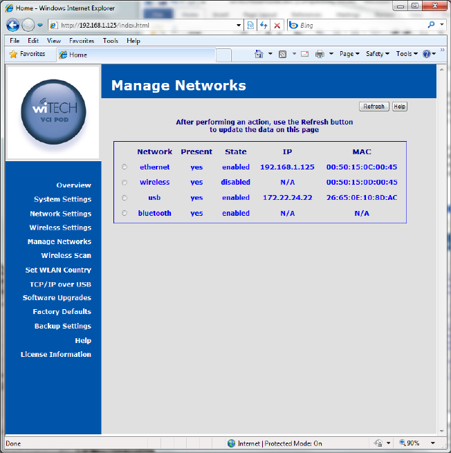
Manage Networks
You will have one or more network interfaces on the device, such as Ethernet,
WLAN, USB, and Bluetooth. Ethernet and WLAN interfaces can have one or
more sets of configuration data, referred to as a profile. Profiles are manipulated
on the Network and Wireless Settings pages. The Manage Networks page
allows you to make a configuration profile active for an interface. You can restart
the Ethernet interface, and stop/start/restart the WLAN interface. The USB
interface can only be restarted as it is also present and active. The Bluetooth
interface is provided via an optional wiTECH SmartCable. If present and enabled
11
this screen offers a button to restart the interface if some problem is encountered
and customer support asks you to restart the interface.
Ethernet Adapter
The Ethernet network interface is always present and active on this device. The
device is factory configured with a default profile that is initially set to obtain an IP
Address via DHCP. You can change this profile on the Network Settings page.
Enable Button Enable the interface when it has been previously disabled
Disable Button Disable the interface, preventing any traffic across the
interface
Restart Button This button can be used to restart the Ethernet network
interface with the currently active profile settings.
Status Shows the current state of the interface, Active, Started, and
Disabled
IP Address The IP address currently assigned to this device, either via
DHCP or static assignment. If no IP Address is listed the
network connection may be down or the Ethernet cable might
be unplugged.
Profiles A list of profiles containing configuration settings for the
Ethernet network interface is provided here. The settings in
use will be shown as Currently Active. Other available
profiles will have a Make Active button next to the profile
name that allows you to change the settings used by the
Ethernet interface and restart the network.
Wireless Adapter (optional)
The Wireless LAN network interface is a device hardware option. When it is
present, a factory configured default profile initially set to obtain an IP Address
via DHCP is provided. However, the access point and security information will
need to be entered via the Wireless Settings page.
Enable Button Enable the interface when it has been previously disabled
Disable Button Disable the interface, preventing any traffic across the
interface
Restart Button This button can be used to restart the Wireless LAN network
interface with the currently active profile settings.
Status Shows the current state of the interface, Active, Started, and
Disabled
IP Address The IP address currently assigned to the WLAN interface,
either via DHCP or static assignment. If no IP Address is
listed the network connection may be down, the access point
security settings are incorrect, or the wireless access point is
unreachable.
AP Address The access point hardware address is provided here. It is
taken directly from the access point when a wireless
12
connection is established. If the address shows as all 0s no
connection is present.
Profiles A list of profiles containing configuration settings for the
Wireless LAN network interface is provided here. The
settings in use will be shown as Currently Active. Other
available profiles will have a Make Active button next to the
profile name that allows you to change the settings used by
the Wireless LAN interface and restart the network.
Bluetooth Adapter (optional)
The Bluetooth network interface is provided in an optional vehicle cable. When it
is present, the device can make a connection to a Bluetooth enabled PC. A zero
configuration IP (ZCIP) address will be used. The Bluetooth and WLAN network
interfaces cannot be used concurrently. Enabling one will force the other to be
disabled.
Enable Button Enable the interface when it has been previously disabled
Disable Button Disable the interface, preventing any traffic across the
interface
Restart Button This button can be used to restart the Bluetooth network
interface.
Status Shows the current state of the interface, Active, Started, and
Disabled
IP Address The IP address currently assigned to the Bluetooth interface
via ZCIP.
USB Adapter
The USB network interface is provided via the USB connector on the device. The
connector can be found on the faceplate just below the antenna. The USB cable
provided with the device when purchased should be used. Connect the mini-
connector end to the device and the other end to a Windows PC which has the
Bright Star Engineering Ethernet Gadget drivers installed. A DHCP server is
provided on the device to assign an IP address to the PC when connected over
the USB interface. Refer to the TCP/IP over USB web page description further
on in this document for more information.
Restart Button This button can be used to restart the USB network interface
should a problem occur
Status Shows the current state of the interface, Active, Started, and
Disabled
IP Address The IP address currently assigned to the Bluetooth interface
via static assignment.
13
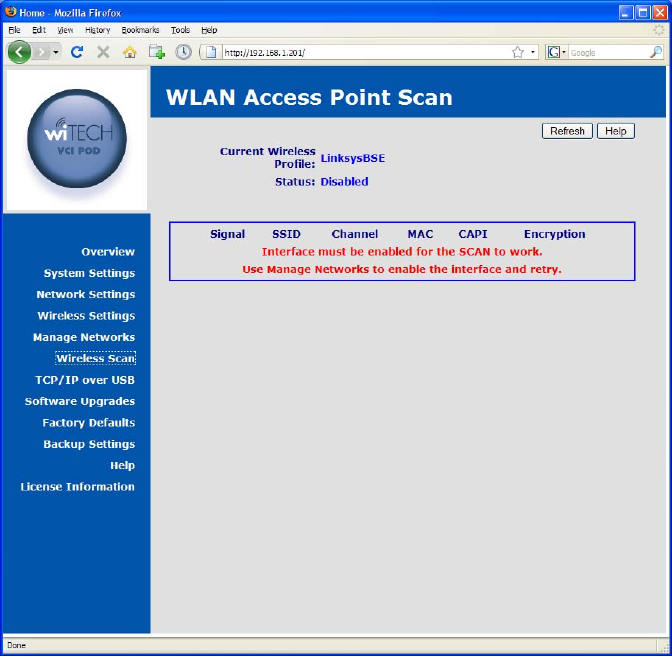
Wireless Scan
Use this utility to scan for available wireless networks at your location. Some
networks may not be visible if the wireless access point(s) has been configured
to not broadcast the SSID. Please note that the wireless interface on the device
must be enabled for this feature to work.
14
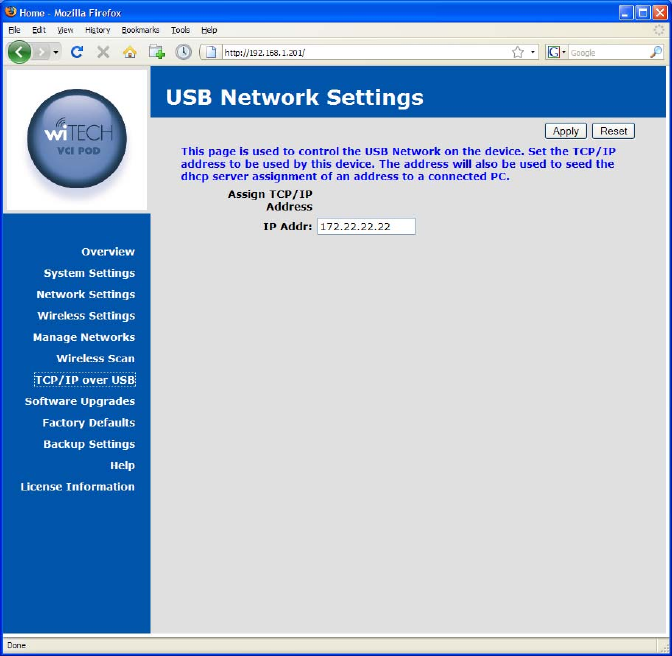
TCP/IP over USB
This page is used to configure the TCP/IP address to be used for the USB based
network. This device can be connected directly to a Microsoft Windows PC with
a USB cable. When connected, a TCP/IP network will be created between the
device and the Windows PC over the USB cable. The TCP/IP address entered
on this page will be assigned to the device and used to seed the DHCP address
assigned to the Windows PC.
15
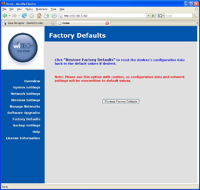
Factory Defaults
Use this page to reset the device configuration settings back to the factory
default values. Note: Please use this option with caution, as configuration data
and network settings will be overwritten to default values.
16
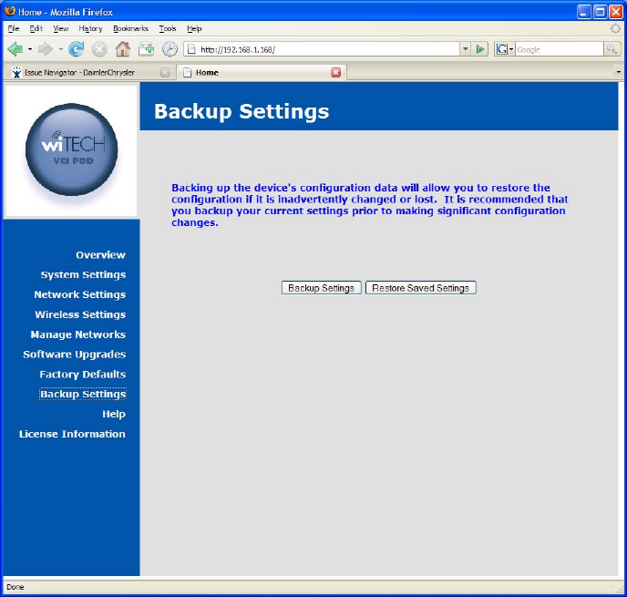
Backup Settings
Back up the device's configuration data via this page. This will allow you to save
and restore the configuration if it is inadvertently changed or lost. It is
recommended that you backup your current settings prior to making significant
configuration changes.
17
Software
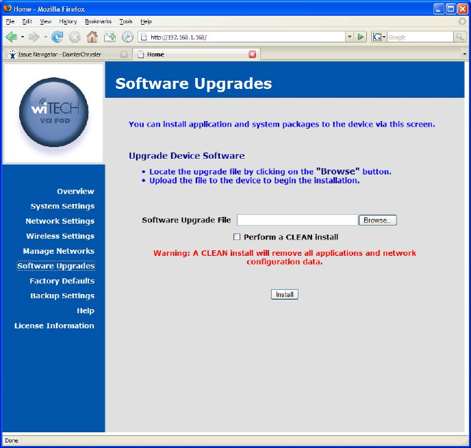
Software Upgrades
Using the HTTP Installer
The Software Upgrades page on the device configuration web site allows you to
install platform software and firmware upgrades. Use the Browse button on this
screen to locate the software package on the local machine and click on the
Install button to initiate the upload of the package file. Once uploaded the
upgrade will be automatically started. Once the upgrade begins you will loose
your browser connection to the device. The BUSY LED will be turned on to
indicate the upgrade is being performed. The software upgrade notification
screen will attempt to refresh to indicate the upgrade is complete.
If you wish to reset the device during the upgrade process, click on the checkbox
labeled as Perform a CLEAN Install.
If a failure occurs during the upgrade, all LEDs will be turned on to indicate a
problem exists. If this should occur follow the procedure outlined below.
18
Recovering from a Failed Upgrade
In the event a platform software and firmware upgrade fails in such a way that
the device cannot operate normally, remove and then reattach the device power
source. The device will reboot into a recovery mode. In this mode the device will
boot into a limited configuration that will allow you to apply a product software
upgrade via the provided web interface. You should not attempt to use the
device for anything but a software upgrade when in recovery mode.
Installing Applications
Applications are installed in the same manner as platform software and firmware
upgrades, using the Software Upgrades web page. Use the Browse button on
this screen to locate the software package on the local machine and click on the
Install button to initiate the upload of the package file. Once uploaded the
upgrade will be automatically started. If the application provides progress
information, it will be displayed in a popup window opened by the Software
Upgrades web page.