BroMax Communications WM253 11 Mbps Wireless WLAN Mini Module User Manual PCMCIA 11M Wireless LAN Card User s Manual
BroMax Communications Inc 11 Mbps Wireless WLAN Mini Module PCMCIA 11M Wireless LAN Card User s Manual
UserManual.wiki
>
BroMax Communications
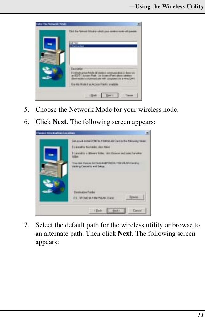
>
WM253 User Manual
Users Manual
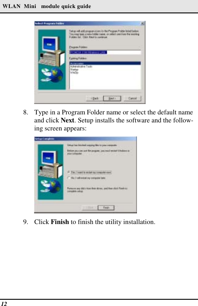
Navigation menu
Upload a User Manual
Namespaces
Wiki Guide
HTML
PDF
Info
Views
User Manual
Discussion / Help
Navigation