Broadcast Microwave Services Europe and KG CT6540ARI6466 TV Auxiliary Equipment User Manual 605169301N TAA 101 sm
Broadcast Microwave Services Europe GmbH & Co. KG TV Auxiliary Equipment 605169301N TAA 101 sm
Contents
- 1. Installation Instructions
- 2. User Manual
Installation Instructions

TAA-101/TAA-101S ANTENNA ACTUATOR
Installation/Operation Manual
Doc. No. 605169301 Rev. N

Broadcast Microwave Services, Inc. ▪ 12367 Crosthwaite Circle, Dock 10 ▪ Poway, CA 92064 ▪ USA
Tel: +1 (858) 391-3050 ▪ Toll-free (US): 800-669-9667 ▪ Fax: +1 (858) 391-3049 ▪ support@bms-inc.com ▪ www.bms-inc.com
Broadcast Microwave Services Europe GmbH & Co. KG ▪ Schwalbacher Str. 12 ▪ 65321 Heidenrod Germany Tel: +49-6124-72
39-00 ▪ Fax: +49-6124-72 39-29
2011 Broadcast Microwave Services. All rights reserved.
This document and the information contained in it is the property of Broadcast Microwaves Services, Inc. and may be the subject of
patents pending and granted. It must not be used for commercial purposes nor copied, disclosed, reproduced, stored in a retrieval
system or transmitted in any form or by any means (electronic, mechanical, photocopying, recording or otherwise), whether in whole
or in part, without BMS prior written agreement.
TAA-101/TAA-101S Antenna Actuator Manual | Doc. No. 605169301 Rev. M
Broadcast Microwave Services, Inc. i
Document Revision History
Initial release 2006 Rev. -
Subsequent updates 2006-2008 Rev. A through G
Added Figure 9, Caution, page 15 March 2009 Rev. H
Added installation and removal tool instructions, starting page 18 October 2009 Rev. J
Updated max speed figure to correspond to STC. January 2010 Rev. K
Updated speed, deployment figures based on new calculations; added drawings March 2010 Rev. L
Included TAA-SM-22 (P/N 8001272972) November 2010 Rev. M
Adjusted RF exposure distance due to latest test reports August 2011 Rev. N
Conventions Used in This Manual
NOTE: Notes provide supplementary information. They are highlighted for emphasis, as in this
example, and are placed immediately after the relevant text.
CAUTION: Cautions give information which, if strictly followed, will prevent damage to equipment or
other goods. They are boxed for emphasis, as in this example, and are placed immediately preceding
the point at which the reader requires them.
WARNING: Warnings give information which, if strictly observed, will prevent personal injury or
death, or damage to personal property or the environment. They are boxed and shaded for emphasis,
as in this example, and are placed immediately preceding the point at which the reader requires
them.
ATTENTION!
CAUTION: DO NOT use right-angle connectors or adapters on the RF Power Out cable assemblies.
Right-angle connectors may have significant RF power loss at the operating frequencies of this
system.
CAUTION: FOR ALL BMS TRANSMITTERS: Operation of this product generally requires a license.
It is the responsibility of the user to obtain all required operating licenses.
FOR PRODUCTS AWAITING FCC CERTIFICATION: This device has not been authorized as required
by the rules of the US Federal Communications Commission. This device is not, and may not be,
offered for sale or lease, or sold or leased, in the US until authorization is obtained.
NOTE: Actual Acceptance Test Procedure (ATP) Test Data results by product serial number are
shipped with all units and indicate the equipment to be operating within advertised specifications.
Read and Follow Instructions
All safety and operating instructions should be read before this product is operated. All operating and use
instructions should be followed. This manual should be retained for future reference.
EMC Compliance
This equipment is certified to the EMC requirements detailed in the technical specifications. To maintain
this certification, only use the cables supplied or if in doubt contact BMS Customer Service.
TAA-101/TAA-101S Antenna Actuator Manual | Doc. No. 605169301 Rev. M
Broadcast Microwave Services, Inc. ii
RF Exposure Information
For body worn operation, the device has been tested and meets FCC RF exposure guidelines when used
with an accessory that contains no metal and that positions device a minimum of 57 cm (when a 6dBi
antenna is used) from the body. Use of other accessories may not ensure compliance with FCC RF
exposure guidelines.
TAA-101/TAA-101S Antenna Actuator Manual | Doc. No. 605169301 Rev. M
Broadcast Microwave Services, Inc. iii
Contents
1
INTRODUCTION ................................................................................................................................................... 1
2
SYSTEM DESCRIPTION ...................................................................................................................................... 2
2.1
TAA-101 and TAA-101S Components and Accessories ............................................................................... 5
2.2
Technical Specifications ............................................................................................................................... 8
3
INSTALLATION/SETUP ..................................................................................................................................... 21
3.1
Deciding the Component Locations ............................................................................................................ 22
3.2
Installing the Mounting Bracket ................................................................................................................... 22
3.3
Cable Routing ............................................................................................................................................. 23
3.4
Installing the Up/Down Box ......................................................................................................................... 23
3.5
Cable Termination ...................................................................................................................................... 24
3.6
Antenna Installation .................................................................................................................................... 24
3.7
Installing the Antenna Actuator (TAA-101 or TAA-101S) ............................................................................ 24
3.8
Removing the Antenna Actuator (TAA-101 or TAA-101S) .......................................................................... 27
4
USER INTERFACE ............................................................................................................................................. 29
5
OPERATION ....................................................................................................................................................... 30
6
PREVENTIVE MAINTENANCE .......................................................................................................................... 31
6.1
Maintenance Schedule ............................................................................................................................... 31
6.2
Maintenance Procedures ............................................................................................................................ 31
7
WARRANTY ....................................................................................................................................................... 33
7.1
Customer Service Information .................................................................................................................... 33
8
TROUBLESHOOTING ........................................................................................................................................ 34
8.1
Connector Pin-outs ..................................................................................................................................... 34
List of Figures
Figure 1. Cross-tube strut mount.................................................................................................................................... 3
Figure 2. Low profile skid mount .................................................................................................................................... 4
Figure 3. Low profile and 4-inch lift skid mounts ............................................................................................................ 4
Figure 4. Low profile skid mount outline drawing ........................................................................................................... 7
Figure 5. Four-inch lift skid mount outline drawing ......................................................................................................... 8
Figure 6. TAA-101 left side mount (LSM) ....................................................................................................................... 9
Figure 7. TAA-101 right side mount (RSM) .................................................................................................................. 10
Figure 8. TAA-101S ..................................................................................................................................................... 11
Figure 9. TAA-101, left side, exploded view ................................................................................................................. 12
Figure 10. TAA-101 outline drawing ............................................................................................................................. 13
Figure 11. Weldment, Hughes 300, skid mount, low profile omni deployment ............................................................. 14
Figure 12. Bell 412 with 4.0" lift skid mount, weldment ................................................................................................ 15
Figure 13. TAA-101 retract/deploy switch schematic ................................................................................................... 16
Figure 14. Typical wiring, TAA-101 in analog application ............................................................................................. 17
Figure 15. Up-Down Box deployment control (analog) ................................................................................................. 18
Figure 16. Typical wiring, TAA-101 in digital application .............................................................................................. 19
Figure 17. TAA-101 drag vs. speed graph ................................................................................................................... 20
Figure 18. TAA-101 interconnect diagram ................................................................................................................... 21
Figure 19. Cross-tube mount assembly ....................................................................................................................... 23
Figure 20. Actuator Installation and Removal tools ...................................................................................................... 25
Figure 21. Position of detent pins ................................................................................................................................. 25
Figure 22. Aligning the actuator (sealed actuator shown) ............................................................................................ 26
Figure 23. Using the actuator installation tool .............................................................................................................. 26
Figure 24. Actuator correctly mounted ......................................................................................................................... 27
Figure 25. Using the actuator removal tool on forward and rear pins ........................................................................... 28
Figure 26. Up/Down Box interface ............................................................................................................................... 29
Figure 27. Alternate deployment control ...................................................................................................................... 29
Figure 28. Product label ............................................................................................................................................... 33
TAA-101/TAA-101S Antenna Actuator Manual | Doc. No. 605169301 Rev. M
Broadcast Microwave Services, Inc. iv
List of Tables
Table 1. TAA-101 components and accessories ............................................................................................................ 5
Table 2. Actuator mounting bracket assemblies............................................................................................................. 6
Table 3. Antenna actuator characteristics ...................................................................................................................... 8
Table 4. Deployment control unit.................................................................................................................................... 8
TAA-101/TAA-101S Antenna Actuator Manual | Doc. No. 605169301 Rev. M
Broadcast Microwave Services, Inc. v
Page left intentionally blank

TAA-101/TAA-101S Antenna Actuator Manual | Doc. No. 605169301 Rev. M
Broadcast Microwave Services, Inc. 1
1 INTRODUCTION
The TAA-101 Antenna Actuator Assembly deploys an omni-directional antenna below the aircraft allowing
unrestricted views between the omni and ground sites. Both the TAA-101 and the TAA-101S are
designed to avoid line-of-sight obstacles created by aircraft features that might interfere with
transmission. This greatly enhances continuous communication between the helicopter and its associated
transmit and/or receive site. The TAA-101S Antenna Actuator is sealed for harsh environments.
This dependable low cost antenna actuator may be skid- or cross-tube-strut mounted. A breakaway
release mechanism assures safety if the antenna is still deployed when the helicopter lands.
Features:
• Low cost
• Lightweight
• 360° azimuth coverage
• Quick installation
• In-flight deployment
• Stows for landing
• TAA-101S for harsh environments
• Deployed/stowed indicators
This document provides instructions for the installation, operation and maintenance of both the TAA-101
and the TAA-101S Antenna Actuator Assemblies.
NOTE: A safety placard is referenced in the relevant STC. The placard’s BMS part number is
200169303.
Broadcast Microwave Services (BMS) is a leader in wireless digital microwave technology providing
innovative products for the television broadcast, video, telemetry and surveillance industries. A wholly
owned subsidiary of Cohu, Inc., BMS designs and manufactures a comprehensive line of microwave
communications equipment for broadcasting sports venues, law enforcement and military applications.
BMS also builds and integrates command and control centers to provide fully functioning, complex, end to
end digital systems.
For the latest product and system information please visit www.bms-inc.com.
Please e-mail us at techpubs@bms-inc.com about this and other BMS manuals.
Broadcast Microwave Services, Inc.
12367 Crosthwaite Circle, Dock 10
Poway, CA 92064
Tel: +1 (858) 391-3050
Toll-free (US only): 800-669-9667
Fax: +1 (858) 391-3049
Email: sales@bms-inc.com
Web: www.bms-inc.com

TAA-101/TAA-101S Antenna Actuator Manual | Doc. No. 605169301 Rev. M
Broadcast Microwave Services, Inc. 2
2 SYSTEM DESCRIPTION
The TAA-101 and TAA-101S Antenna Actuator Assemblies consist of the Antenna Actuator that deploys
the antenna; a Bracket Mount Assembly used to attach the Actuator to the Helicopter; the Up/Down Box
to control the actuator; and the interconnection cables.
The main components of the Antenna Actuator are a gear head motor, worm and worm gear assembly.
The gear head motor is pinned to the worm and drives the worm gear when the motor is energized with a
24 to 32 volt dc signal. The motor/worm combination in turn drives the worm gear assembly. The polarity
of the dc signal determines the direction that the motor turns. Therefore, connecting dc of one polarity will
deploy the antenna, and reversing the polarity will stow the antenna. At both ends of the travel of the
worm gear, a roll pin in the side of the worm gear actuates a limit switch. When the switch is opened the
power to the motor is disconnected and the unit will remain in this position until a command is given
(reversed polarity voltage) to move in the opposite direction. The worm/worm gear combinations are of
the type that cannot be back driven; therefore power is not required to maintain the position of the
antenna. The Antenna Actuator is available in sealed and non-sealed versions as well as configurations
for left or right side mounting depending on the application.
The Antenna Actuator Assembly has two hardened steel pins on the side of the unit, which snap into
sockets on the Bracket Mount Assembly. The Bracket Mount Assembly has spring-loaded release pins
that retain the Antenna Actuator Assembly. This is to provide a weak link to protect the aircraft in the
event the helicopter is landed with the antenna deployed. The release pins allow the Antenna Actuator to
detach to prevent damage to the helicopter.
CAUTION: Landing with the antenna deployed will damage the antenna.
When the actuator is in the stowed position the omni is parallel to the skid and above ground level and
does not interfere with take off or landing of the helicopter.
There are several types of Bracket Mount Assemblies depending on the application. This document
applies to the cross tube strut mount and skid mount assemblies:
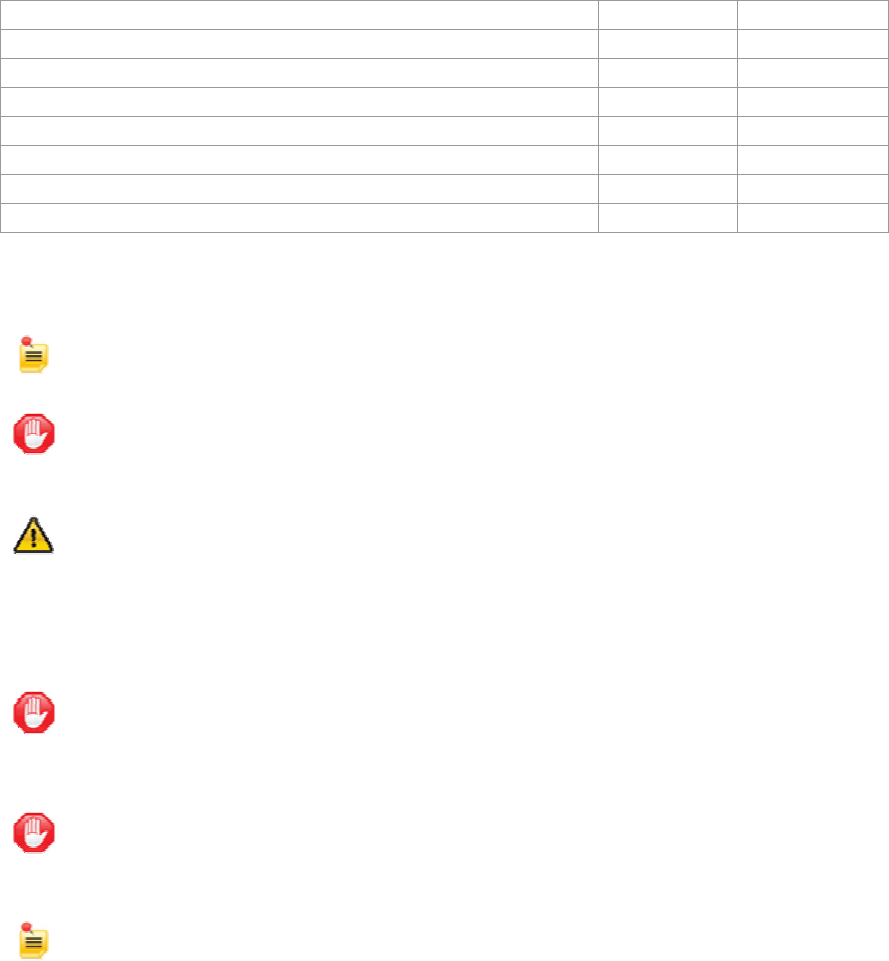
• a cross-tube strut mount bracket assembly (Figure 1):
o P/N 810140225 – 2.25” dia.
o P/N 810140250 – 2.50” dia.
o P/N 810140260 – 2.60” dia.
• a low profile skid mount bracket assembly;
• a low profile skid mount bracket assembly with BMT75 mount;
• a 4-inch lift skid mount bracket assembly.
The cross-tube strut mount bracket assembly (Figure 1) attaches to the struts of the helicopter.
TAA-101/TAA-101S Antenna Actuator Manual | Doc. No. 605169301 Rev. M
Broadcast Microwave Services, Inc. 3
Figure 1. Cross-tube strut mount
TAA-101/TAA-101S Antenna Actuator Manual | Doc. No. 605169301 Rev. M
Broadcast Microwave Services, Inc. 4
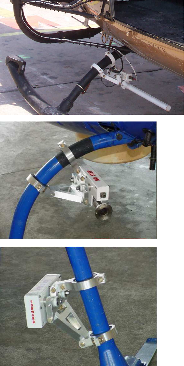
The low profile skid-mount bracket assembly (Figure 2) is attached to the helicopter skid by using
stainless steel clamps. Since the skid diameters vary on the different makes of helicopters, bracket
assemblies are available to accommodate several of the more popular helicopters.
Figure 2. Low profile skid mount
The low profile bracket assembly with BMT75 mount functions the same as the low profile bracket and
has a place to mount a BMS BMT75 transmitter directly to the bracket.
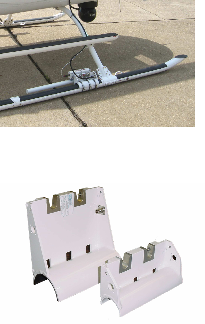
The 4-inch lift skid mount bracket assembly (Figure 3) is a taller version of the low profile bracket
assembly, it functions the same but the 4-inch lift provides an advantage in some applications.
Figure 3. Low profile and 4-inch lift skid mounts

TAA-101/TAA-101S Antenna Actuator Manual | Doc. No. 605169301 Rev. M
Broadcast Microwave Services, Inc. 5
Deployment of the antenna actuator is controlled by the Up/Down Box which also supplies it with power.
There are other deployment control units available as part of an integrated broadcast system (HCP-50,
HCP-100, HCP-50-HCII). Please contact BMS for more information on integrated systems.
2.1 TAA-101 and TAA-101S Components and Accessories
All TAA-101 or TAA-101S assemblies require the antenna actuator, skid mount, and a device for
deployment control. The following table lists the available options and corresponding part numbers.
Table 1. TAA-101 components and accessories
Component Description
Part
Number
Antenna Actuator
Kit, TAA-101-LSM, Left Side Mounting 870169302
Kit, TAA-101-RSM, Right Side Mounting 870169304
TAA-101S-L, Left Side Mounting with RF
cable 800169324
TAA-101S-R, Right Side Mounting with RF
cable 800169323
Deployment
Control
TAA-101-UD Up/Down Box 800195701
Cables
1–7GHz Cable Set 730805000
20” Replacement Cable for TAA-101S
1
610805025
Tools
TAA-101 Installation and Removal Tools Kit 870169391
TAA-101 Installation Tool 800169391
TAA-101 Removal Tool 800169392
1
Replaces the cable from the TAA-101 to the Omni Antenna for both Cable Sets

TAA-101/TAA-101S Antenna Actuator Manual | Doc. No. 605169301 Rev. M
Broadcast Microwave Services, Inc. 6
Table 2. Actuator mounting bracket assemblies
TAA-101 Actuator Mounts with NON-MEMORY Release Pins
Helicopter Skid Diameter
(inches) BMS Part # Type
Hughes 300 2.500 8001272951 Skid Mount
Hughes 500 2.800 8001272952 Skid Mount
MD 500 2.800 8001272952 Skid Mount
Robinson R44 2.800 8001272952 Skid Mount
Bell 206/206B 3.000 8001272953 Skid Mount
Bell Jet Ranger 3.000 8001272953 Skid Mount
Eurocopter EC-120 3.000 8001272953 Skid Mount
Aerospatiale 3.200 8001272954 Skid Mount
Astar AS 350 (B) 3.200 8001272954 Skid Mount
Bell 214B 4.125 8001272955 Skid Mount
Bell 222/230/412 4.125 8001272955 Skid Mount
UH1 Hughie 4.125 8001272955 Skid Mount
Robinson R22 2.000 8001272956 Skid Mount
MD 600 3.500 8001272957 Skid Mount
Eurocopter EC-135 3.750 8001272958 Skid Mount
MD-900 3.320 8001272959 Skid Mount
MD 500/R44 2.800 8001272960 Skid Mount w/
BMT75
Jet Ranger/206B 3.000 8001272961 Skid Mount w/
BMT75
BLIMP 1.500 8001272962 Skid Mount
Eurocopter 1.500 8001272963 Step mount w/
BMT75
Super Puma Mount N/A 8001272964 Belly Mount
Blackhawk N/A 8001272965 Belly Mount
Bell 222/230/412 4.125 8001272966 Skid Mount w/ 4" Lift
Jet Ranger 206B/EC-120 3.000 8001272967 Skid Mount w/ 4" Lift
Aerospatiale 3.200 8001272968 Skid Mount w/ 4" Lift
American Eurocopter BK-
117A3 3.500 8001272969 Skid Mount
American Eurocopter BO-105
3.548 8001272970 Skid Mount
AUGSTA BELL AB-212 3.937 8001272971 Skid Mount
Schweizer Model 333 2.250 8001272972 Skid Mount
TAA-101/TAA-101S Antenna Actuator Manual | Doc. No. 605169301 Rev. M
Broadcast Microwave Services, Inc. 7
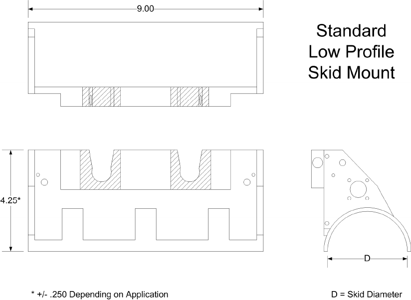
Figure 4. Low profile skid mount outline drawing
TAA-101/TAA-101S Antenna Actuator Manual | Doc. No. 605169301 Rev. M
Broadcast Microwave Services, Inc. 8
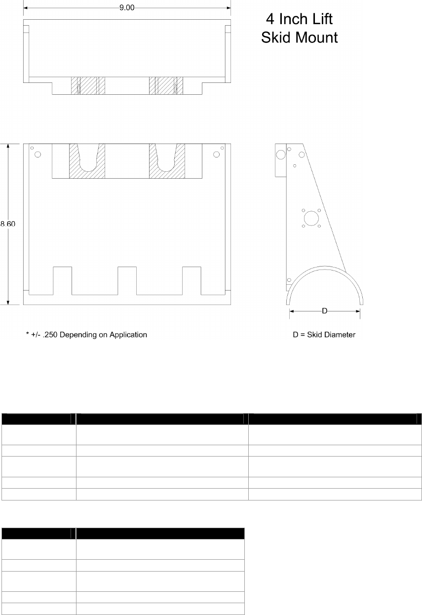
Figure 5. Four-inch lift skid mount outline drawing
2.2 Technical Specifications
Table 3. Antenna actuator characteristics
TAA-101 (Left or Right) TAA-101S (Left or Right)
Size 9.125” x 1.86” x 4.0” (23.18 x 4.72 x 10.16
cm)
8.62" x 1.74" x 4.87" (21.89 x 4.42 x 12.37
cm)
Weight < 5 lbs (2.27 kg) < 6 lbs (2.72 kg)
Voltage
Required 24 – 34 VDC 24 – 34 VDC
Power 32 W Max. 32 W Max.
Operating Temp -4 to + 140 ºF (-20 to +60º C) -4 to + 140 ºF (-20 to +60º C)
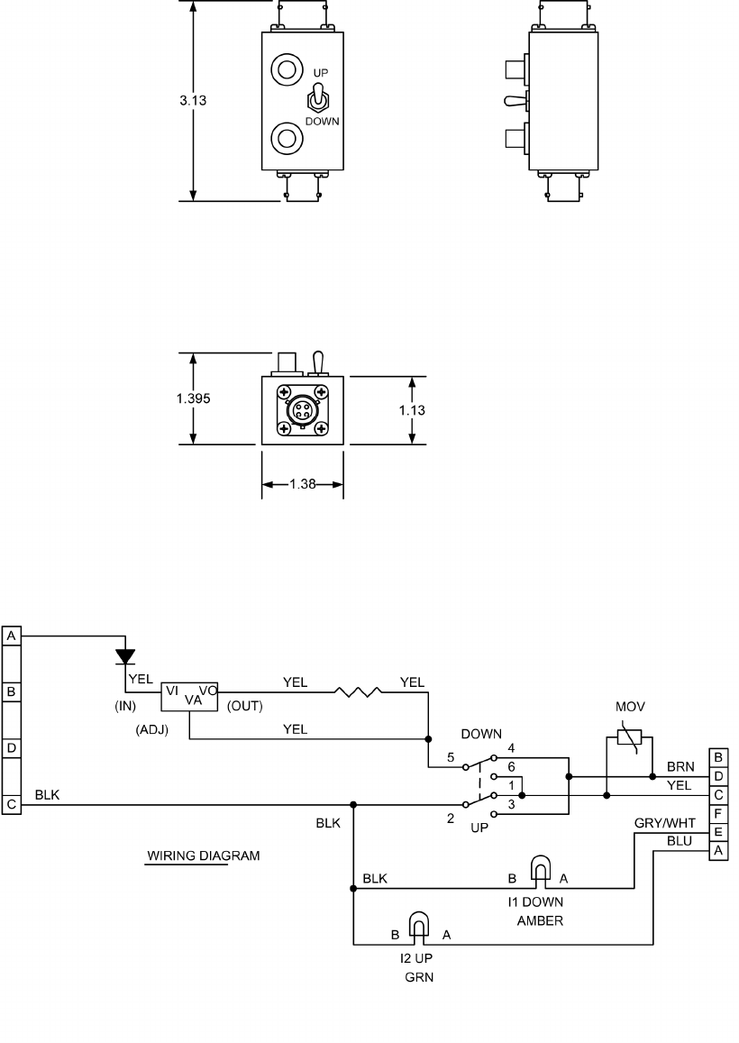
Table 4. Deployment control unit
Up/Down Box
Size 3.13” x 1.38” x 1.395” (8.41 x 3.51 x 3.54
cm)
Weight .4 lb (.18 kg)
Voltage
Requi
red
28 – 32 VDC
Power 1 A
Operating Temp -4 to + 140 ºF (-20 to +60º C)
TAA-101/TAA-101S Antenna Actuator Manual | Doc. No. 605169301 Rev. M
Broadcast Microwave Services, Inc. 9
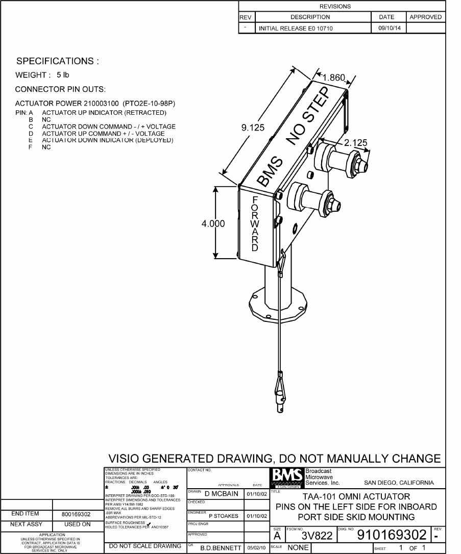
Figure 6. TAA-101 left side mount (LSM)
TAA-101/TAA-101S Antenna Actuator Manual | Doc. No. 605169301 Rev. M
Broadcast Microwave Services, Inc. 10
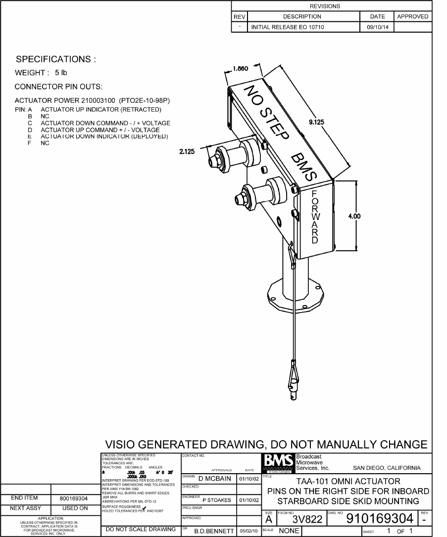
Figure 7. TAA-101 right side mount (RSM)
TAA-101/TAA-101S Antenna Actuator Manual | Doc. No. 605169301 Rev. M
Broadcast Microwave Services, Inc. 11
Figure 8. TAA-101S
TAA-101/TAA-101S Antenna Actuator Manual | Doc. No. 605169301 Rev. M
Broadcast Microwave Services, Inc. 12
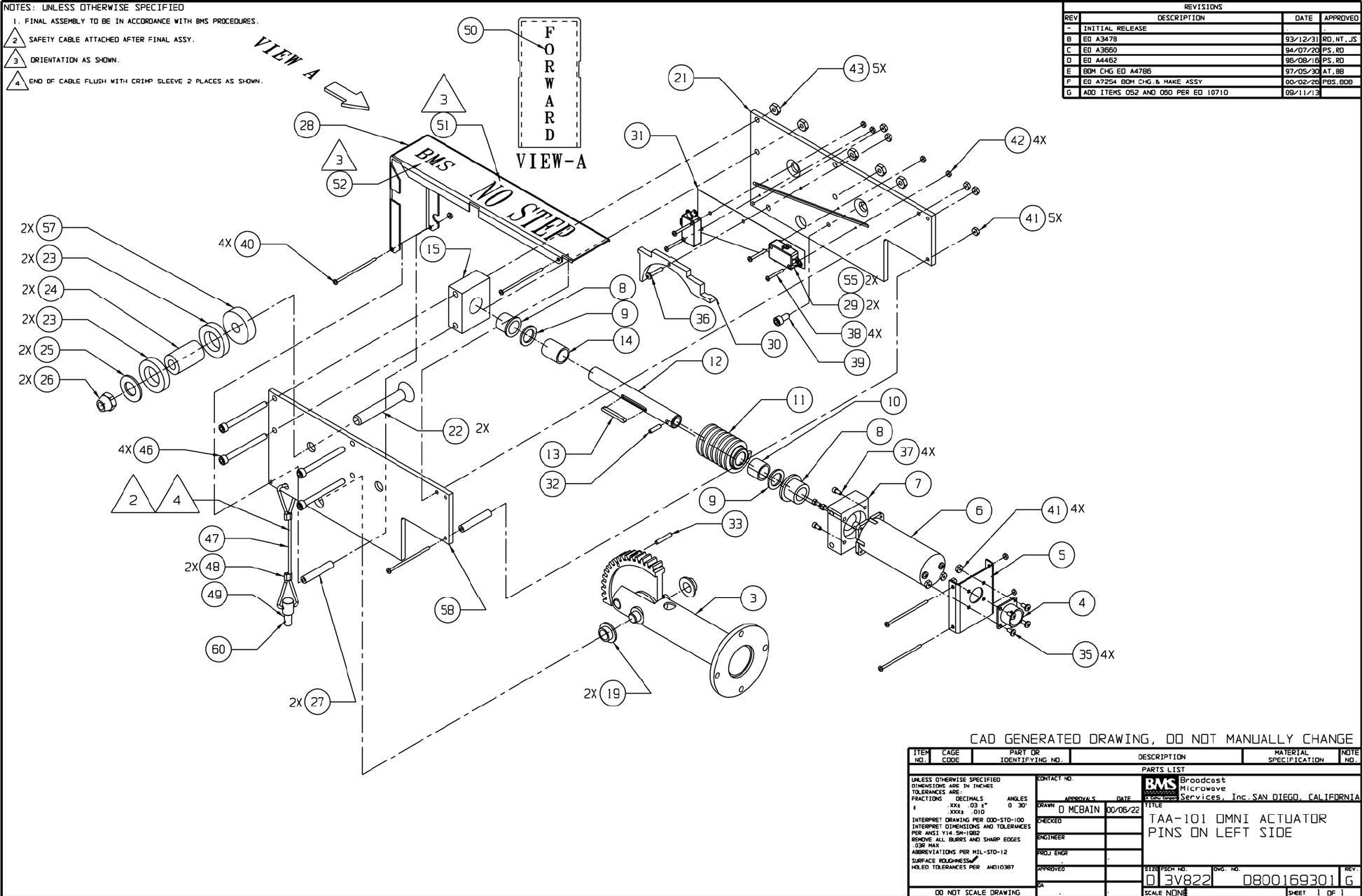
Figure 9. TAA-101, left side, exploded view
TAA-101/TAA-101S Antenna Actuator Manual | Doc. No. 605169301 Rev. M
Broadcast Microwave Services, Inc. 13
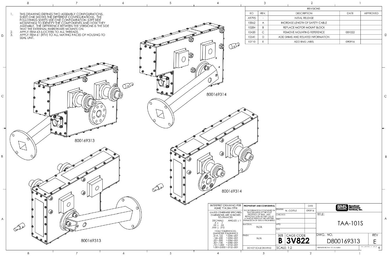
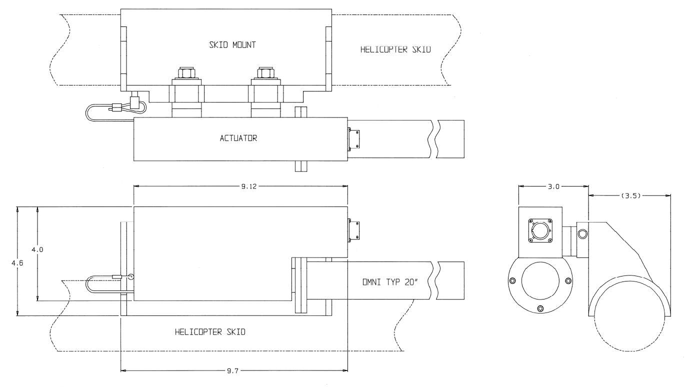
Figure 10. TAA-101 outline drawing
TAA-101/TAA-101S Antenna Actuator Manual | Doc. No. 605169301 Rev. M
Broadcast Microwave Services, Inc. 14
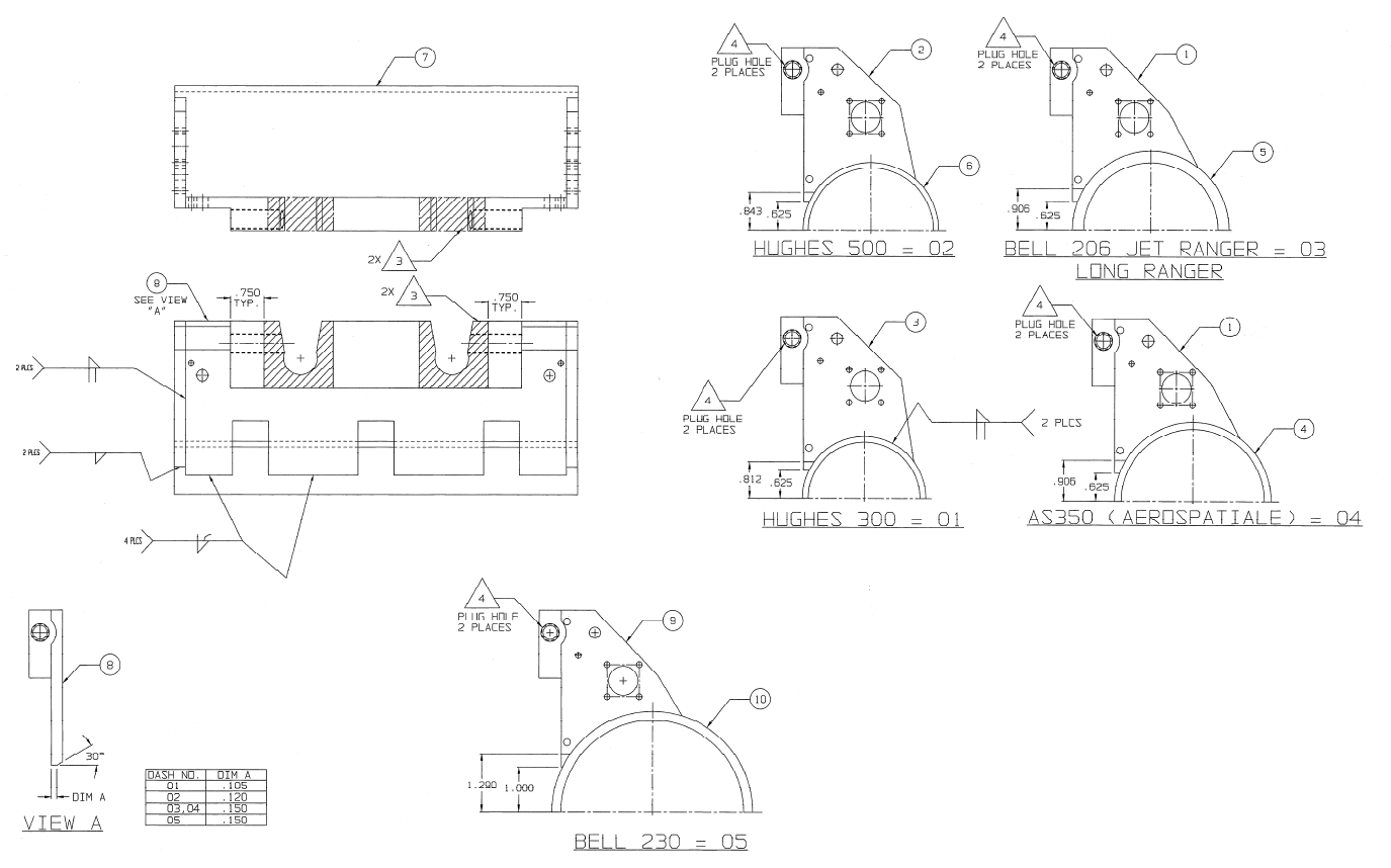
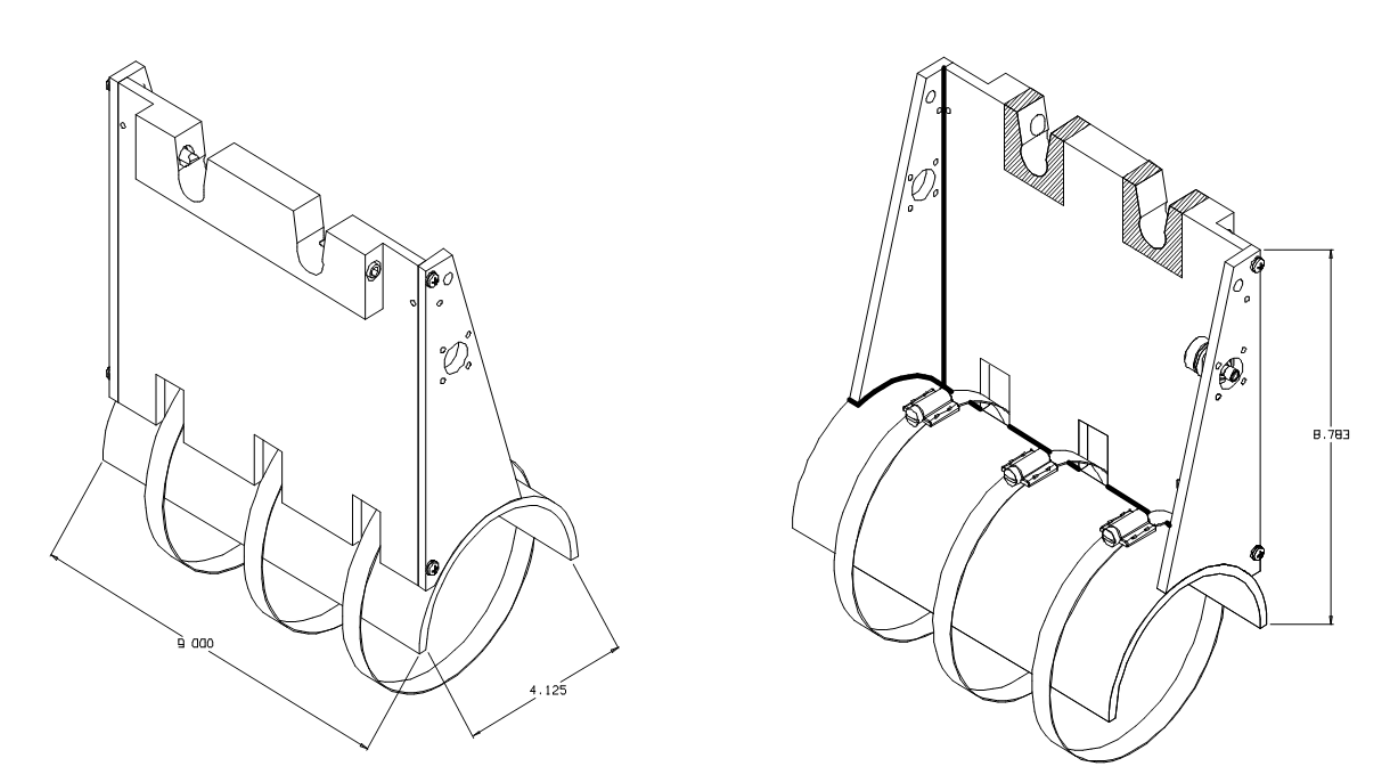
Figure 11. Weldment, Hughes 300, skid mount, low profile omni deployment
TAA-101/TAA-101S Antenna Actuator Manual | Doc. No. 605169301 Rev. M
Broadcast Microwave Services, Inc. 15
Figure 12. Bell 412 with 4.0" lift skid mount, weldment
TAA-101/TAA-101S Antenna Actuator Manual | Doc. No. 605169301 Rev. M
Broadcast Microwave Services, Inc. 16
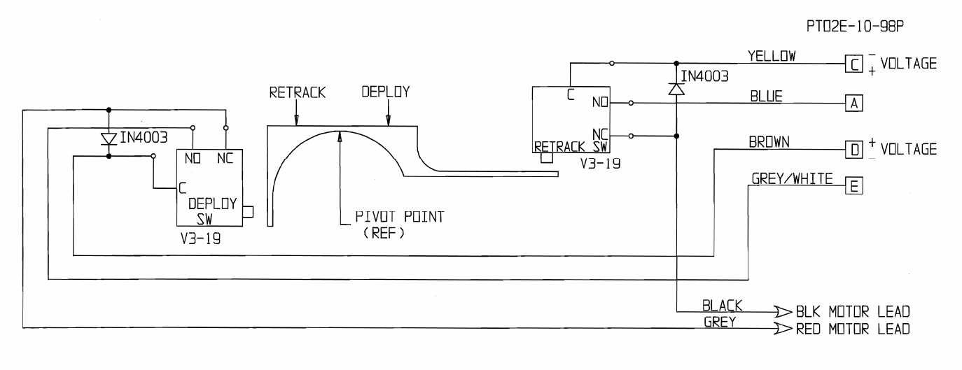
Figure 13. TAA-101 retract/deploy switch schematic
TAA-101/TAA-101S Antenna Actuator Manual | Doc. No. 605169301 Rev. M
Broadcast Microwave Services, Inc. 17
Figure 14. Typical wiring, TAA-101 in analog application
TAA-101/TAA-101S Antenna Actuator Manual | Doc. No. 605169301 Rev. M
Broadcast Microwave Services, Inc. 18
Figure 15. Up-Down Box deployment control (analog)
TAA-101/TAA-101S Antenna Actuator Manual | Doc. No. 605169301 Rev. M
Broadcast Microwave Services, Inc. 19
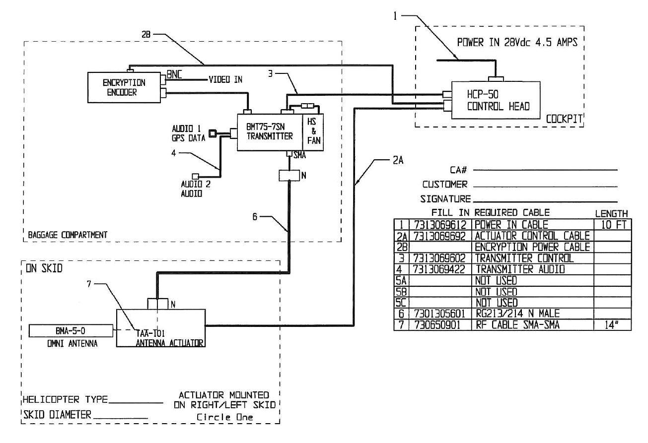
Figure 16. Typical wiring, TAA-101 in digital application
TAA-101/TAA-101S Antenna Actuator Manual | Doc. No. 605169301 Rev. M
Broadcast Microwave Services, Inc. 20
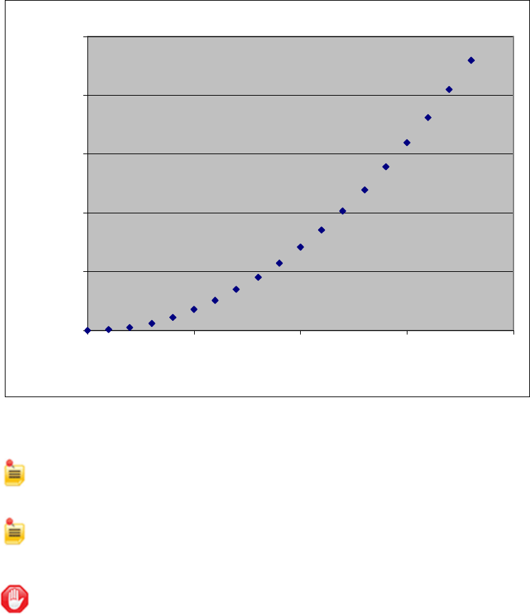
Drag Vs. Speed
0.00
5.00
10.00
15.00
20.00
25.00
0 50 100 150 200
Velocity (mph)
Force (lbs)
Figure 17. TAA-101 drag vs. speed graph
NOTE: The values in Figure 17 are calculated using the actuator with the BMS 20”
omni antenna.
NOTE: If the TAA-101 is to be installed using an FAA STC, then please observe V
ne
(not-to-exceed velocity) as stated in the STC.
CAUTION:
•
A forward velocity in excess of 140 knots may cause the actuator to stall.
•
Do not exceed 145 knots forward speed with antenna deployed.
TAA-101/TAA-101S Antenna Actuator Manual | Doc. No. 605169301 Rev. M
Broadcast Microwave Services, Inc. 21
3 INSTALLATION/SETUP
NOTE: Installation should only be performed by an FAA Certified A/P or Avionics Technician.
Each component should be installed in compliance with FAA regulations and accepted industry practices.
Some antenna mounts have been granted STC authorization by the FAA for particular aircraft; other
installations may require additional inspection/authorization. All equipment is to be installed based on the
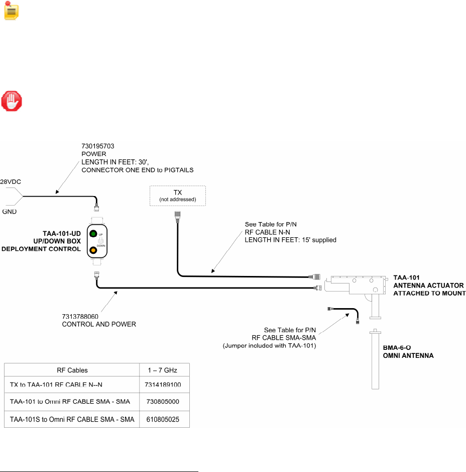
following wiring diagram.
CAUTION: DO NOT use right-angle connectors or adapters on the RF Power Out cable assemblies.
Right-angle connectors may have significant RF power loss at the operating frequencies of this
system.
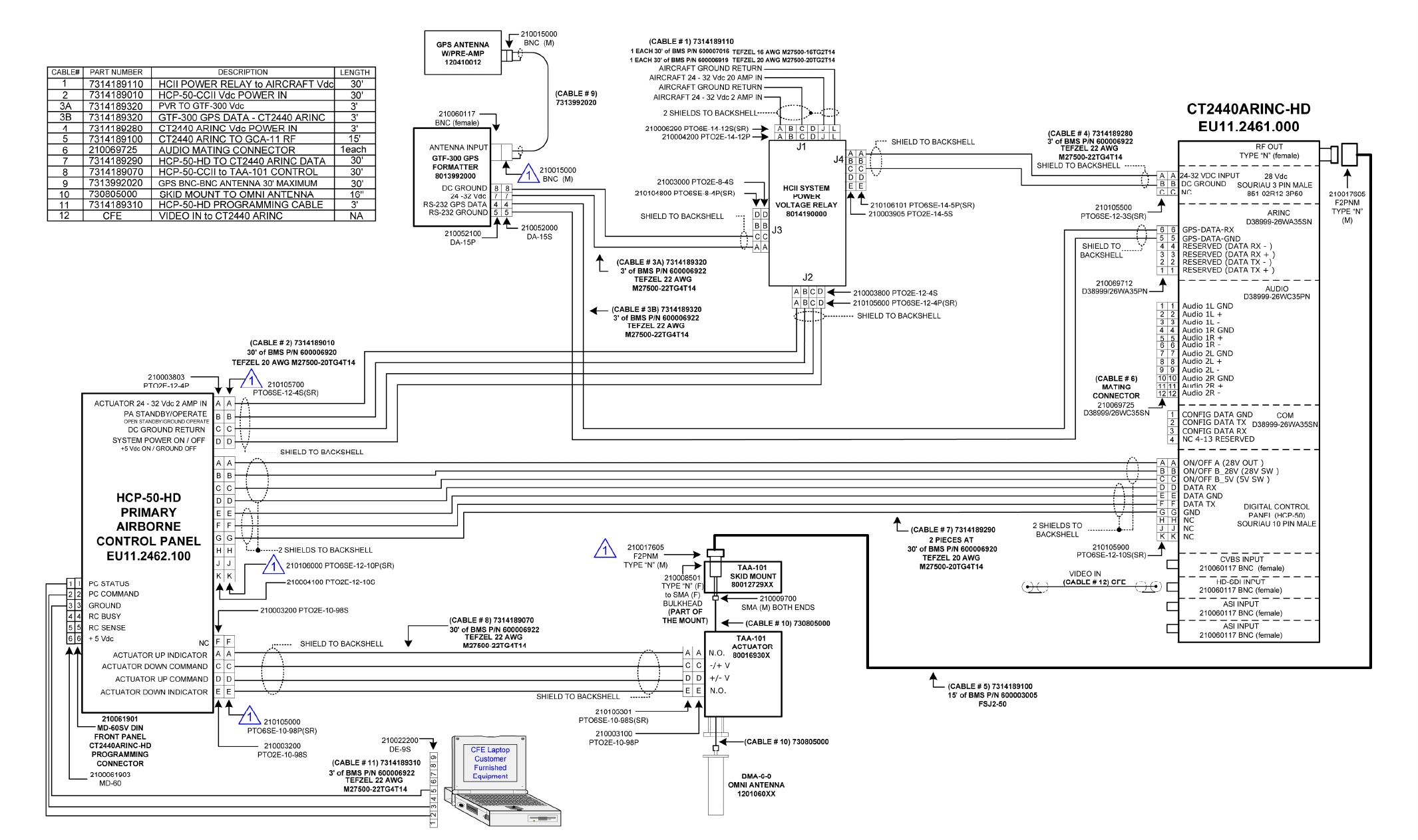
Figure 18. TAA-101 interconnect diagram
The TAA-101 and TAA-101S are side-specific. The side of the aircraft on which the TAA-101/TAA-101S
is to be installed is specified at the time of equipment order. The order of installation is as follows:
1. Decide where components will be located.
2. Install mounting bracket.
3. Install deployment control unit.
4. Route cables and terminate.
5. Install omni antenna.

TAA-101/TAA-101S Antenna Actuator Manual | Doc. No. 605169301 Rev. M
Broadcast Microwave Services, Inc. 22
6. Install actuator.
3.1 Deciding the Component Locations
The placement of the mounting bracket and actuator are a function of aircraft structure, center of gravity,
pilot visibility and functionality. The attachment of the mounting bracket must be structurally sound. The
location should be such that the pilot can easily see whether the antenna is deployed or not. The actuator
is mounted inboard so that antenna is deployed against forward motion. The “Forward” signage on the
actuator must always face toward the front of the aircraft.
NOTE: The TAA-101/TAA-101S must be installed on the side specified at the time of order.
The cables are routed through the helicopter from the aircraft power to the Up/Down box, then from the
Up/Down Box to the TAA-101 or TAA-101S. The RF cable from the transmitter will be routed to the
Mounting Bracket of the TAA-101 and TAA-101S. The smaller RF cable routes from the Mounting Bracket
to the Omni Antenna.
The Deployment Control Unit is installed in the cockpit within reach of the pilot. There are several types of
Deployment Control for the TAA-101 and TAA-101S. The Up/Down Box is the only unit with the sole
function to deploy and retract the antenna actuator. Other Deployment Control Units have additional
features and are not covered by this documentation. Please refer to the proper documentation on the
specific Deployment Control Unit for information on installation, operation and maintenance.
3.2 Installing the Mounting Bracket
The TAA-101 or TAA-101S is attached to the helicopter by a Mounting Bracket. The specific mounting
bracket was selected at the time of order. Installation procedures for each type are as follows:
•
Skid Mount Bracket Installation
•
Cross Tube Strut Mount Bracket Installation
3.2.1 Skid Mount Bracket Installation
This procedure applies to the standard low profile skid mount, 4-inch Lift Skid Mount, and Skid Mount with
BMT75 Transmitter Mount.
CAUTION: All Skid Mount Brackets must be attached directly to the skid. DO NOT clamp the
skid mount bracket to the skid protection tubes. The Skid Mount can be installed on either
side of aircraft.
1. Once the location for the Skid Mount Bracket Assembly has been chosen, secure the Bracket
Assembly to the skid. The tube section sits on top of the skid with the thick metal vertical piece on
the inside of the skid towards the center of aircraft.
2. The Bracket Assembly may now be secured to the skid using the three stainless steel hose clamps.
These are placed through the slots in the bracket and around the skid. It may be necessary to lift the
skid off the ground about
⅛
inch to put the clamps under the skid.
3. Before securing the clamps, position the skid mount so the antenna will deploy straight down
(vertical metal piece of the bracket is perpendicular to the ground). Torque the band clamps to 50 in-
lbs.
3.2.2 Cross Tube Strut Mount Bracket Installation
The Cross Tube Strut Mount (Figure 19) has two hinged clamps that can be secured to a single cross-
tube strut. Three diameter sizes are available:
•
P/N 810140225 – 2.25” dia.
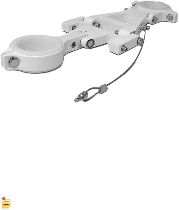
TAA-101/TAA-101S Antenna Actuator Manual | Doc. No. 605169301 Rev. M
Broadcast Microwave Services, Inc. 23
•
P/N 810140250 – 2.50” dia.
•
P/N 810140260 – 2.60” dia.
1. Orient the mount so the antenna will deploy straight down (the notches are facing up).
2. Attach the top clamp to the strut.
3. Loosen the bottom clamp support and adjust the angle so that the bottom clamp mates up with the
strut.
Figure 19. Cross-tube mount assembly
4. Secure the bottom clamp to the strut.
5. Secure the upper clamp support.
3.3 Cable Routing
1. Now that the Mounting Bracket has been installed, the final cable lengths can be determined.
2. Set the actuator assembly on the bracket. Do not snap the unit into the bracket at this time.
3. Proceed with routing the Power and RF cables from their destinations in the aircraft to the actuator.
4. Place grommets around any hole drilled to prevent cable damage.
5. Secure cables every 6 to 12 inches.
NOTE: Maintain signal integrity by minimizing the losses due to sharp bends in the RF cable and
90° RF connectors.
3.4 Installing the Up/Down Box
The Up/Down Box is mounted to the center console or cyclic control using Velcro strips. It is positioned so
it is easily viewed by the pilot and will not interfere with normal in-flight operations.

TAA-101/TAA-101S Antenna Actuator Manual | Doc. No. 605169301 Rev. M
Broadcast Microwave Services, Inc. 24
3.5 Cable Termination
Once final cable lengths have been determined after running the cables between the installed
components, they may be terminated.
3.6 Antenna Installation
To install the antenna onto the TAA-101 Actuator, the actuator will need to be extended first to allow
proper access to all the mounting holes. The TAA-101S does not need to extend the actuator prior to
antenna installation.
3.6.1 Antenna Installation on TAA-101
1. Remove the TAA-101 from the mounting bracket.
2. Connect the Power Cable to the TAA-101.
3. Using the Up/Down Box, extend the actuator.
4. Feed the RF cable into the hole on the side of the antenna mount through the center.
5. Connect the RF Cable to the Omni antenna.
6. Attach the omni antenna to the antenna mount with four ANS-10 screws, four MS21044N3 nuts and
eight AN960-10 washers. Torque the fasteners to 20 to 25 in. lbs.
3.6.2 Antenna Installation on TAA-101S
1. Feed the RF cable into the hole on the side of the antenna mount through the center.
2. Connect the RF cable to the omni antenna.
3. Attach the omni antenna to the antenna mount with four ANS-10 screws, four MS21044N3 nuts and
eight AN960-10 washers. Torque the fasteners to 20 to 25 in. lbs.
4. Connect the Power Cable to the TAA-101S.
3.7 Installing the Antenna Actuator (TAA-101 or TAA-101S)
NOTE:
•
The “FORWARD” signage must always face the front of the aircraft.
•
The radome of the omni antenna is easily damaged. Handle the unit with caution.
•
A forward velocity in excess of 140 knots may cause the actuator up/down motor to stall.
This procedure requires the use of the Installation and Removal tool kit, P/N 870169391. The kit contains
two tools (Figure 20), one for installing the actuator, P/N 800169391, and one for removing it, P/N
800169392.
TAA-101/TAA-101S Antenna Actuator Manual | Doc. No. 605169301 Rev. M
Broadcast Microwave Services, Inc. 25
Figure 20. Actuator Installation and Removal tools
1. Ensure the skid mount bracket is mounted to the skid, if not already done. See section 3.2.
2. Retract the actuator so that the omni antenna is in the stow position (if it is not already).
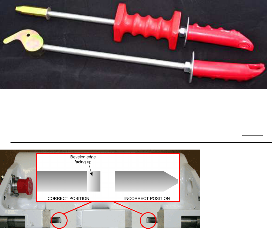
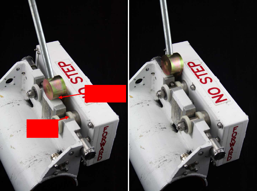
3. If not already positioned, rotate the detent pins (Figure 21) so their beveled ends face up. THIS IS
VERY IMPORTANT! FAILURE TO ALIGN THE PINS IN THIS WAY MAY DAMAGE THE PRODUCT!
Figure 21. Position of detent pins
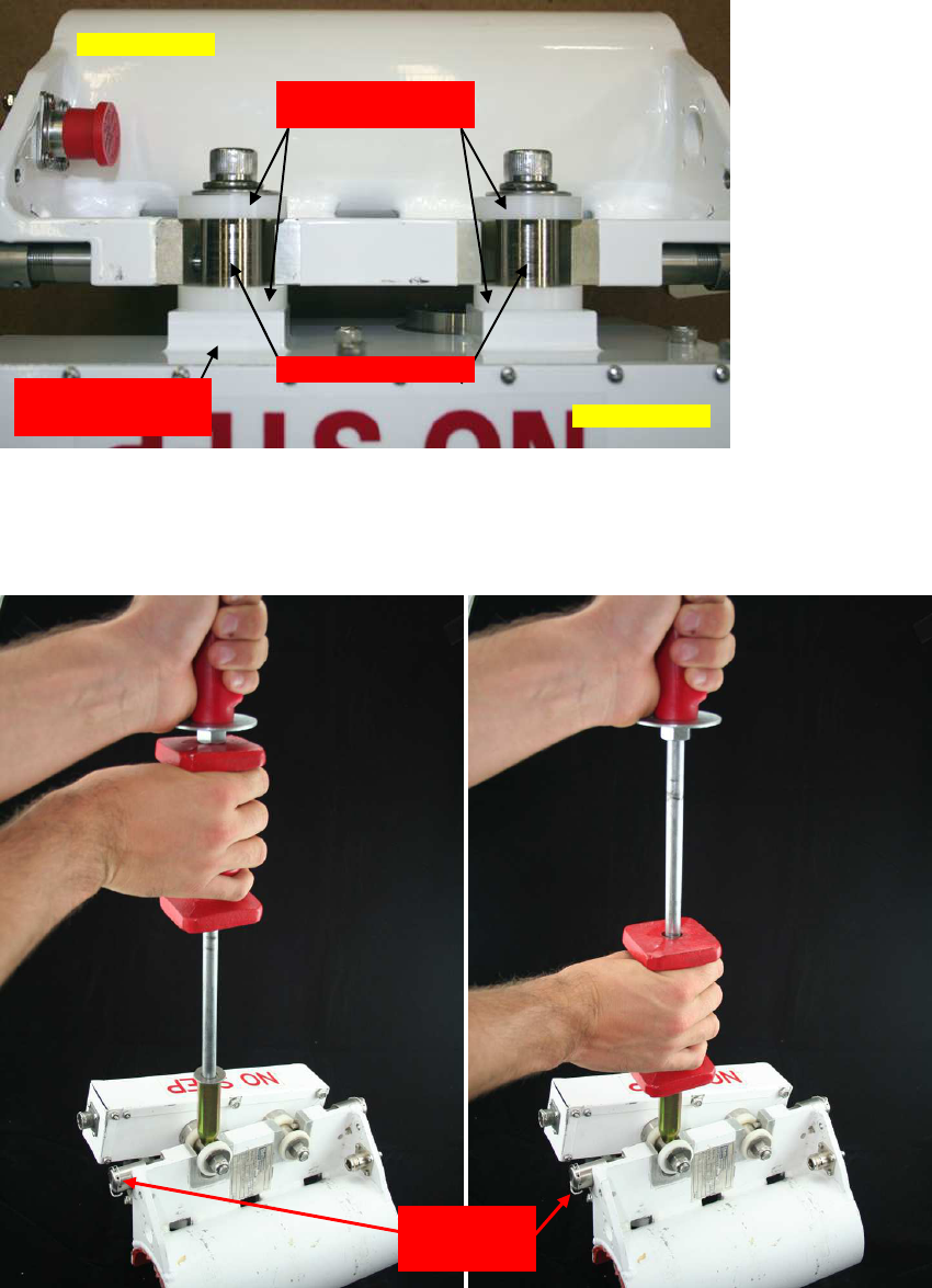
4. Place the actuator on the mounting bracket as shown in Figure 22. One plastic washer must be
positioned on each side of the bracket, as shown. Note that the sealed actuator is shown in the figure;
the unsealed actuator does not have the square-shaped boss, shown.
TAA-101/TAA-101S Antenna Actuator Manual | Doc. No. 605169301 Rev. M
Broadcast Microwave Services, Inc. 26
Figure 22. Aligning the actuator (sealed actuator shown)
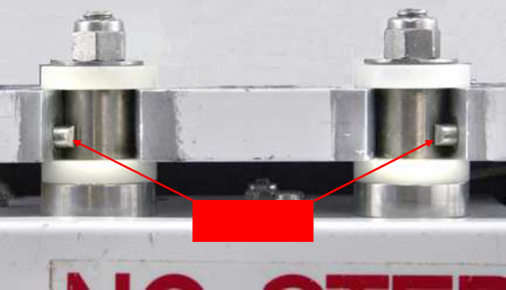
5. Insert the square end of the TAA-101 installation tool (P/N 800169391) on the first actuator mounting
pin, as shown in Figure 23. Note that the tool is positioned between each washer.
Figure 23. Using the actuator installation tool
Actuator mounting
pins
Square-shaped boss
(sealed actuator
Plastic washers
positioned correctly
Mounting
Sealed
Mounting
bracket’s
spring
-
loaded
TAA-101/TAA-101S Antenna Actuator Manual | Doc. No. 605169301 Rev. M
Broadcast Microwave Services, Inc. 27
6. Slide the tool’s red plunger up, then down quickly and with enough force to push the actuator
mounting pin into position. It takes considerable force to ensure the pin slides past the mounting
bracket’s spring-loaded detent pin.
7. Repeat step 5 for the other pin. The correctly mounted actuator is shown in Figure 24.
Figure 24. Actuator correctly mounted
8. Rotate the TAA-101 or TAA-101S unit with the antenna attached so that the antenna is straight up.
9. Cycle the actuator several times between stowed and deployed while monitoring whether the RF
cable connected to the antenna is binding. Adjust the cable as needed to eliminate any binding.
10. Retract the actuator to the stowed position.
3.8 Removing the Antenna Actuator (TAA-101 or TAA-101S)
Removing the actuator requires the Removal tool, P/N 800169392.
1. Insert the tool’s hooked end under the actuator mounting pin washer, as shown in Figure 25. Its round
base should rest on the mounting bracket. NOTE: For sealed actuators, DO NOT place the hooked
end under the square-shaped boss.
Detent pins extend
fully across actuator
mounting pins
TAA-101/TAA-101S Antenna Actuator Manual | Doc. No. 605169301 Rev. M
Broadcast Microwave Services, Inc. 28
Figure 25. Using the actuator removal tool on forward and rear pins
2. With the tool positioned correctly, pull the tool back slowly and firmly to lift the actuator mounting pin
past the mounting bracket’s spring-loaded catch.
3. Repeat step 2 for the other mounting pin.
Tool’s round
base rests on
mounting
H
ooked end
positioned
under
TAA-101/TAA-101S Antenna Actuator Manual | Doc. No. 605169301 Rev. M
Broadcast Microwave Services, Inc. 29
4 USER INTERFACE
There are several Deployment Control Units available for the TAA-101 and TAA-101S. The Up/Down Box
is the only unit with the sole function to deploy and retract the antenna actuator. Other Deployment
Control Units have additional features not covered by this documentation. Please refer to the proper
documentation for the specific Deployment Control Unit for information on installation, operation and
maintenance.
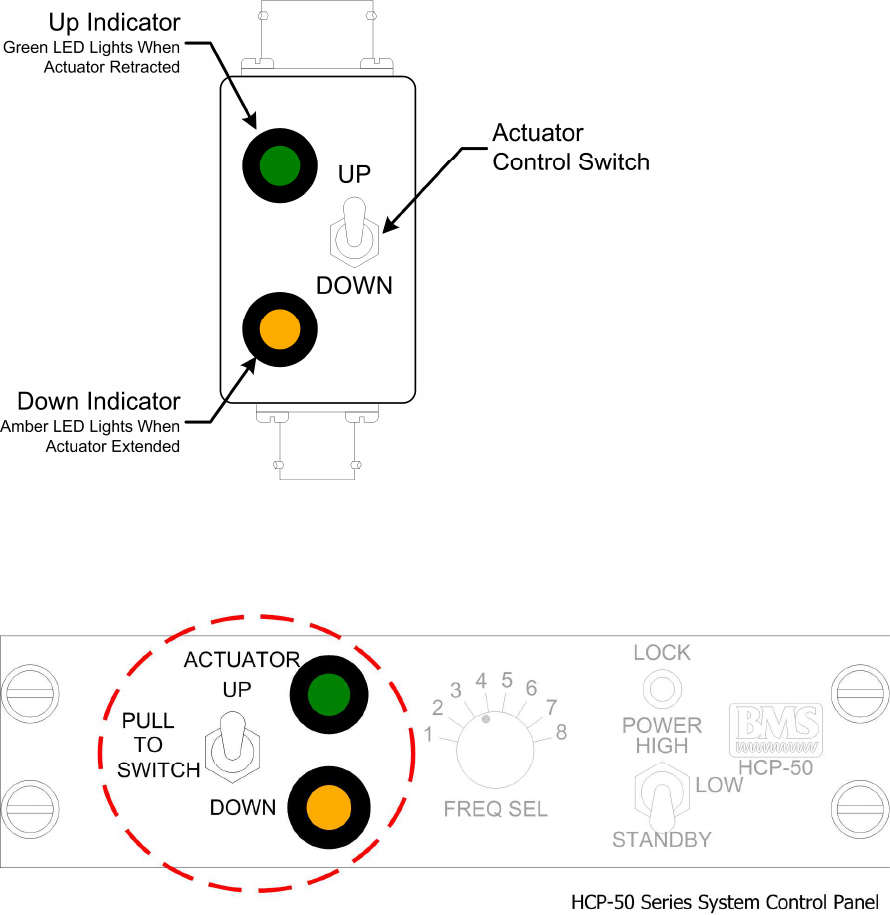
Figure 26. Up/Down Box interface
Below is an example of an alternate Deployment Control that has been incorporated with a transmitter
control in a Helicopter Control Panel (HCP).
Figure 27. Alternate deployment control

TAA-101/TAA-101S Antenna Actuator Manual | Doc. No. 605169301 Rev. M
Broadcast Microwave Services, Inc. 30
5 OPERATION
CAUTION:
•
Follow all procedures precisely to ensure initialization and operation.
•
The TAA-101 and TAA-101S deployment is for IN-FLIGHT operation ONLY.
•
The Antenna needs to be properly STOWED (retracted) prior to take-off and
Landing.
Deploy the antenna by pulling the Actuator Control Switch out and putting it in DOWN position. It takes
the antenna about 15 seconds to deploy. The yellow light will indicate when the antenna is fully deployed.
No lights will indicate when the actuator is between deployed and stowed.
CAUTION:
•
A forward velocity in excess of 140 knots may cause the actuator to stall.
•
Do not exceed 145 knots forward speed with antenna deployed.
Stow the actuator by pulling the Actuator Control Switch out and putting it in the UP position. It takes
about 15 seconds to stow. The green light will indicate when the antenna is properly stowed. No lights will
indicate when the actuator is between deployed and stowed.

TAA-101/TAA-101S Antenna Actuator Manual | Doc. No. 605169301 Rev. M
Broadcast Microwave Services, Inc. 31
6 PREVENTIVE MAINTENANCE
In order to ensure system longevity it is highly recommended that the following preventive maintenance
procedures be done at the appropriate time.
6.1 Maintenance Schedule
Procedure
Every 100 Hours of
Flight
Every
25
Hours of
Flight Preflight
Up/Down Box
Inspect mounting hardware
Inspect wiring (connection,
chafing)
Skid Mount
Inspect clamps for wear
TAA-101
Verify operation
Inspect for debris in
m
echanism
Clean and lubricate
mechanism
Inspect mounting hardware
Inspect wiring (connection,
chafing)
TAA-101S
Verify operation
Inspect mounting hardware
Inspect wiring (connection,
chafing)
6.2 Maintenance Procedures
6.2.1 Operation Verification
1. Use the actuator removal tool, P/N 800169392, to remove the actuator from the rear socket on the
mount. See section 3.8 for instructions.
2. Rotate the TAA-101 so that the antenna can deploy without damage.
3. Power the system, then deploy and retract the antenna.
4. If the TAA-101 is operating correctly, turn off the power and reinstall the actuator into the mount with
the installation tool, P/N 800169391. See section 3.7 for instructions.
5. If the TAA-101 is not operating properly, see the TROUBLESHOOTING section.
6.2.2 Clean and Lubricate TAA-101 Mechanism
1. Remove the actuator from the mounting bracket using the actuator removal tool, P/N 800169392. See
section 3.8 for instructions.
2. Turn the actuator upside down and deploy the antenna to expose the gear.
3. Clean the gear and housing with denatured alcohol to remove all dirt and grit.
4. Inspect for abnormal wear.
TAA-101/TAA-101S Antenna Actuator Manual | Doc. No. 605169301 Rev. M
Broadcast Microwave Services, Inc. 32
5. Lubricate the mechanism by placing 1/8 in. square of lubricant (101 Moly Grease or equivalent) on
each tooth of the brass gear.
6. Retract and deploy the antenna 3 times to work in lubricant.
7. Retract the antenna.
8. Install the actuator onto the mounting bracket using the actuator installation tool, P/N 800169391. See
section 3.7 for instructions.
TAA-101/TAA-101S Antenna Actuator Manual | Doc. No. 605169301 Rev. M
Broadcast Microwave Services, Inc. 33
7 WARRANTY
BMS warrants that, at time of delivery, the product will be free from defects in materials and workmanship
provided the equipment or system is installed, operated and maintained in accordance with the Operation
and Maintenance manual or such other BMS documentation as may be applicable. Any such defect
reported to BMS within two years, BMS will take reasonable and prompt action to repair or replace such
equipment. Should any of the components be defective, please contact BMS immediately. Please have
the following information available so we can best serve you.
•
Customer name, contact name, contract number, and email address;
•
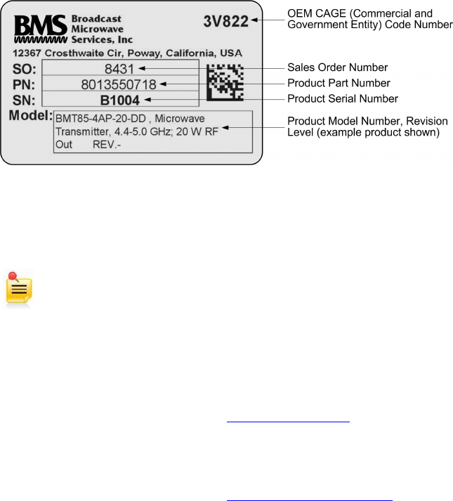
BMS product model number (Figure 28);
•
Product serial number (Figure 28);
•
Detailed description of problem;
•
Return information.
Much of this information can be found on the product label found on the component (Figure 28).
Figure 28. Product label
Defective components under BMS warranty will be repaired/replaced promptly at the discretion of BMS.
Items no longer under warranty will require a PO before repairs can proceed.
NOTE: All goods returned for service require an RMA #. Any goods received without an RMA#
may not be processed in a timely manner. Please contact BMS for an RMA#.
7.1 Customer Service Information
Broadcast Microwave Services, Inc.
12367 Crosthwaite Circle, Dock 10 • Poway, CA 92064 • U.S.A.
Tel: +1-858-391-3050 • Toll Free (U.S.): 866-489-4267 • Fax: +1-858-391-3049
Website: www.bms-inc.com • E-mail: sales@bms-inc.com
Broadcast Microwave Services Europe GmbH & Co. KG
Schwalbacher Str. 12 • 65321 Heidenrod • Germany
Tel: +49-6124-72 39-00 • Fax: +49-6124-72 39-29
Website: www.bms-inc.com • E-mail: saleseurope@bms-inc.com
TAA-101/TAA-101S Antenna Actuator Manual | Doc. No. 605169301 Rev. M
Broadcast Microwave Services, Inc. 34
8 TROUBLESHOOTING
Below is a list of common problems along with the possible causes and solutions.
Fault Cause Solution
TAA-101 Not
Deploying No Power Check Power
Check Cable
Assembly
TAA-101 Not
Retracting
No Power Check Power
Check Cable
Assembly
Debris in
Mechanism Clean Mechanism
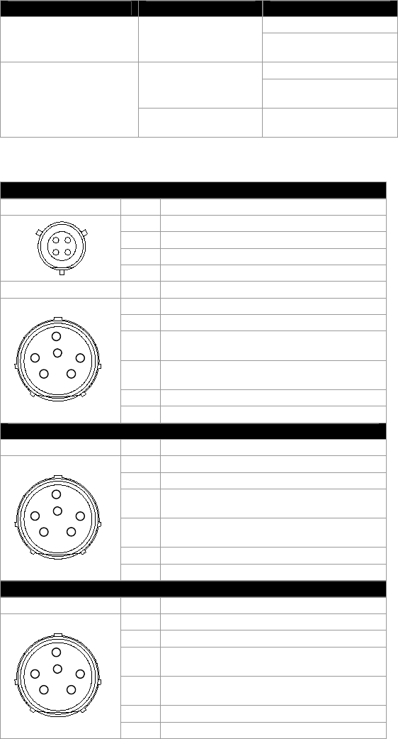
8.1 Connector Pin-outs
Up/Down Box
PTO2E-8-4P PIN
A Power In
B No Connection
C Ground
D No Connection
PTO2E-10-98S PIN
A
EFB
DC
A Actuator Up Indicator (Retracted)
B No Connection
C Actuator Down Command (-/+
VOLTAGE)
D Actuator Up Command ((+/-
VOLTAGE)
E Actuator Down Indicator (Deployed)
F No Connection
TAA-101
PTO2E-10-98P PIN
A
EFB
DC
A Actuator Up Indicator (Retracted)
B No Connection
C Actuator Down Command (-/+
VOLTAGE)
D Actuator Up Command ((+/-
VOLTAGE)
E Actuator Down Indicator (Deployed)
F No Connection
TAA-101S
PTO2E-10-98P PIN
A
EFB
DC
A Actuator Up Indicator (Retracted)
B No Connection
C Actuator Down Command (-/+
VOLTAGE)
D Actuator Up Command ((+/-
VOLTAGE)
E Actuator Down Indicator (Deployed)
F No Connection
TAA-101/TAA-101S Antenna Actuator Manual | Doc. No. 605169301 Rev. M
Broadcast Microwave Services, Inc. 35