Broadcast Microwave Services CCII-4H Carry-Coder II with Power Amplifier User Manual
Broadcast Microwave Services Inc Carry-Coder II with Power Amplifier
User manual
Broadcast Microwave Services, Inc. – 12367 Crosthwaite Circle – Poway, CA 92064 1
Phone: 800-669-9667, 1-858-391-3050 - Fax: 1-858-391-3049
Email: support@bms-inc.com Web: www.bms-inc.com
4 GHz CARRY-CODER II
User Manual
Manual Part Number 6051412900 Rev -
Specifications are subject to change without prior notice.
This document contains confidential information and is intended for customer use only.
It cannot be duplicated without prior authorization from BMS.

Broadcast Microwave Services, Inc. – 12367 Crosthwaite Circle – Poway, CA 92064 2
Phone: 800-669-9667, 1-858-391-3050 - Fax: 1-858-391-3049
Email: support@bms-inc.com Web: www.bms-inc.com
Broadcast Microwave Services, Inc. – 12367 Crosthwaite Circle – Poway, CA 92064 3
Phone: 800-669-9667, 1-858-391-3050 - Fax: 1-858-391-3049
Email: support@bms-inc.com Web: www.bms-inc.com
GLOSSARY
16QAM Quadrature Amplitude Modulation (16 states)
64QAM Quadrature Amplitude Modulation (64 states)
ATSC Advanced Television Standard Committee
COFDM Coded Orthogonal Frequency Division Multiplex
CVBS Composite Video Baseband Signal
DCE Data Communication Equipment
DVB Digital Video Broadcasting
DVB-T Digital Video Broadcasting for Terrestrial TV
EMC Electro-Magnetic Compatibility
EU European Union
GOP Group Of Pictures
MPEG Moving Pictures Engineering Group
PIN Personal Identification Number
PID Packet Identifier
QPSK Quad Phase Shift Keying
US United States of America
LEGEND
= Idea (Highlighted operator Information)
= Warning (indicates a critical or hazardous point)

Broadcast Microwave Services, Inc. – 12367 Crosthwaite Circle – Poway, CA 92064 4
Phone: 800-669-9667, 1-858-391-3050 - Fax: 1-858-391-3049
Email: support@bms-inc.com Web: www.bms-inc.com
WARNING! ........................................................................................................................................................5
OVERVIEW .......................................................................................................................................................7
INSTALLATION................................................................................................................................................9
Mobile and Fixed Platforms............................................................................................................................9
Installation Procedure ...................................................................................................................................10
Installing the Battery on the Carry-Coder II .................................................................................................10
Controlling the CARRY-CODER II Transmitter .........................................................................................11
Control Unit Features................................................................................................................................11
Transmitter Operating Configuration............................................................................................................11
CARRY-CODER II Transmitter <EXPERT> Operating Mode Configuration ...........................................12
OPERATING INSTRUCTIONS ......................................................................................................................12
Start-Up Indications ......................................................................................................................................12
Operator Menu Summary..............................................................................................................................13
INPUT/OUTPUT CHARACTERISTICS.........................................................................................................13
Composite Video (CVBS) ............................................................................................................................13
Component Video (YUV).............................................................................................................................13
Analog Audio................................................................................................................................................14
Data Input......................................................................................................................................................14
Remote Control Port .....................................................................................................................................14
RF Output......................................................................................................................................................15
Power Supply Input.......................................................................................................................................15
WARRANTY AND RETURN TO FACTORY...............................................................................................16
LINEAR POWER AMPLIFIER (BPA-1CC-4)................................................................................................18
Application....................................................................................................................................................18
Specification: ................................................................................................................................................18
CONTACT INFORMATION...........................................................................................................................19

Broadcast Microwave Services, Inc. – 12367 Crosthwaite Circle – Poway, CA 92064 5
Phone: 800-669-9667, 1-858-391-3050 - Fax: 1-858-391-3049
Email: support@bms-inc.com Web: www.bms-inc.com
WARNING!
RF RADIATION EXPOSURE HAZARD
This warning is provided by Broadcast Microwave Services (BMS) Inc. for safety purpose. The following information help
to reduce the risk of RF exposure hazard.
FCC Limit of RF Exposure
According to Federal Communication Commission (FCC), the Maximum Permissible Exposure (MPE) for FR radiation
has been set to 1.0 mW/cm2 for the 4 GHz Carry-Coder II with 1Watt Power Amp equipment (OET Bulletin 65).
The 4 GHz Carry-Coder II with Power Amp is a non-broadcast transmitter and without an antenna it will not create RF
exposure (power density) exceeding the 1.0 W/cm2 FCC limit.
However a high-gain antenna such as a parabolic dish will greatly enhance the 4 GHz Carry-Coder II output power
density beyond the MPE limit of 1.0 mW/cm2.
In this situation a minimum distance from the antenna needs to be calculated in order to keep the MPE always below
the safety limit. The calculation has been done for 4 GHz Carry-Coder II with Power Amp based on the formula
mentioned in OET Bulletin 56.
The calculations have been done for different commonly used antenna in the Public Safety/ Law enforcement
applications.
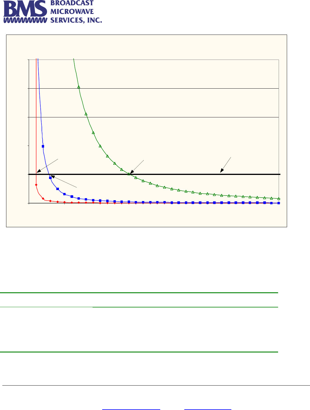
Figure 1 shows the plot of the minimum exposure distance for 5dBi, 16dBi, and 30dBi antennas. The 4 GHz Carry-
Coder II with Power Amp transmits the maximum power of 1Watt. The minimum exposure distances are found from the
cross points of the exposure graphs (for various antennas) with the line of maximum permissible exposure (i.e. 1
W/cm2). Notice that the numbers in Figure 1 predict the worse case scenario, which is straight in front of the antenna
(exposing to the antenna main-lobe). Obviously the side-lobe exposures are well below these numbers as the radiation
intensity dramatically reduces on the side lobes.
Broadcast Microwave Services, Inc. – 12367 Crosthwaite Circle – Poway, CA 92064 6
Phone: 800-669-9667, 1-858-391-3050 - Fax: 1-858-391-3049
Email: support@bms-inc.com Web: www.bms-inc.com
Estimated RF Exposure for 4 GHz Carry-Coder II with Power Amp
0.0
1.0
2.0
3.0
4.0
5.0
0 100 200 300 400 500 600 700
Distance , cm
Power Density, mW/cm^2
Max Permissible
Exposure: 1mW/cm2
30 dBi Antenna
Max Exposure at 280 cm
5 dBi Antenna
Max Exposure at 20 cm
16 dBi Antenna
Max Exposure at 60 cm
Figure 1
Summary
In order the keep the RF exposure within the FCC limit, it is necessary to maintain the safe distance from the antenna.
The results shown in Figures 1 can be summarized in the following table:
Antenna Gain (dBi) Minimum permissible distance from antenna (cm)
5
16
30
20
60
280
Notice the above table indicates worst-case situation (straight in front of the antenna).
Broadcast Microwave Services, Inc. – 12367 Crosthwaite Circle – Poway, CA 92064 7
Phone: 800-669-9667, 1-858-391-3050 - Fax: 1-858-391-3049
Email: support@bms-inc.com Web: www.bms-inc.com
OVERVIEW
4 GHz Carry-Coder II is a mobile transmitter which is used in the 4.95 – 4.99 GHz frequency range. This spectrum has been
assigned to the Public Safety application according to the Subparts 90.1201, 90.1203, and 90.1207 of the FCC regulations.
BMS offers its expertise in the 4GHz Carry-Coder product family with the high-power Carry-Coder II transmitter and companion
COFDM integrated receiver-decoder, the De-Coder II.
The 4GHz Carry-Coder product family includes:
• CARRY-CODER II: Transmitter with 1W external power amplifier.
• DE-CODER II: Rack-mounted COFDM integrated receiver-decoder.
• CARRY DE-CODER II: Mobile COFDM integrated receiver-decoder.
A simple diagram of the 4GHz Carry-Coder II system is shown in Figure 2.
4 GHz Receiver
Microphone
Video Camera
4 GHz Power Amp
RF Out
RF Out
1W Max.
Optional Battery
4 GHz Carry-Coder II
4 GHz
Antenna
4.94 – 4.99 GHz
4 GHz Decoder II
or
4 GHz Carry-Decoder II
400 mW
Max.
Figure 2 Simple system diagram of the 4GHz Carry-Coder II with Power Amplifier
Key features for these products are:
• Robustness
• DVB-T transmission for mobile operation in a multi-path environment.
• High quality, reliable transmission of video and audio in mobile use.
• Flexible audio, video and data interfaces.
• Compact size.
• Low-power consumption.
• The CARRY-CODER II is a mobile device that performs wireless digital transmission of audio, video and data.
• The Carry-Coder II interface consists of video and audio cables.
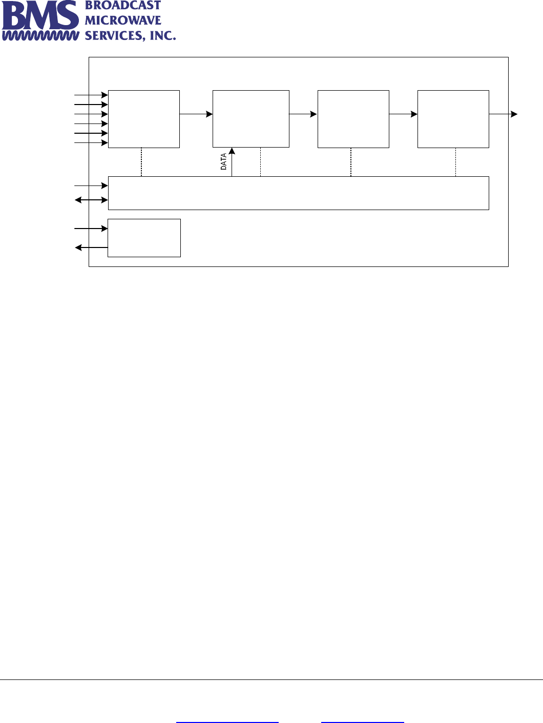
The following block diagram gives an overview of 4 GHz CARRY-CODER II architecture:
Broadcast Microwave Services, Inc. – 12367 Crosthwaite Circle – Poway, CA 92064 8
Phone: 800-669-9667, 1-858-391-3050 - Fax: 1-858-391-3049
Email: support@bms-inc.com Web: www.bms-inc.com
MPEG2
Encoder
(Audio/Video)
DATA Multiplexer COFDM
Modulator
Control Unit
RF Up-
Converter and
Amplifier
Power Supply
Management
+12 to 32 VDC Input
Loop Through
Remote
RS232 (DATA)
RF Output
Carry-Coder II
Y/CVBS In
U In
V In
AL In
AR In
SDI In
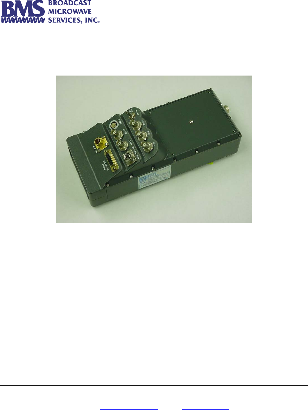
The CARRY-CODER II is comprised of the following sub-systems:
• An MPEG-2 Encoder (1 video channel + 2 audio channels) compliant to ISO/IEC 13818 (MP@ML).
• A Data Multiplexer.
• A COFDM Digital Modulator (“2K” sub-carriers) compliant to ETS 300 744 (the DVB-T standard).
• An RF Up-Converter and RF Amplifier (providing up to 400 mW transmitter output power (without external power amp).
• A detachable hand held remote offering a user-friendly displayed interface for control and system status.
The CARRY-CODER II includes the following input/output connections:
• Composite video input (CVBS)
• SDI input
• Component video input (YUV)
• Analog audio line inputs (L+R)
• ASI Input
• 1 RS232 data interface (for user applications)
• 1 remote control port
• 1 RF output port
• 1 power supply input (11-32VDC nominal)
• 1 battery docking connector with “loop-through” power output.
Broadcast Microwave Services, Inc. – 12367 Crosthwaite Circle – Poway, CA 92064 9
Phone: 800-669-9667, 1-858-391-3050 - Fax: 1-858-391-3049
Email: support@bms-inc.com Web: www.bms-inc.com
INSTALLATION
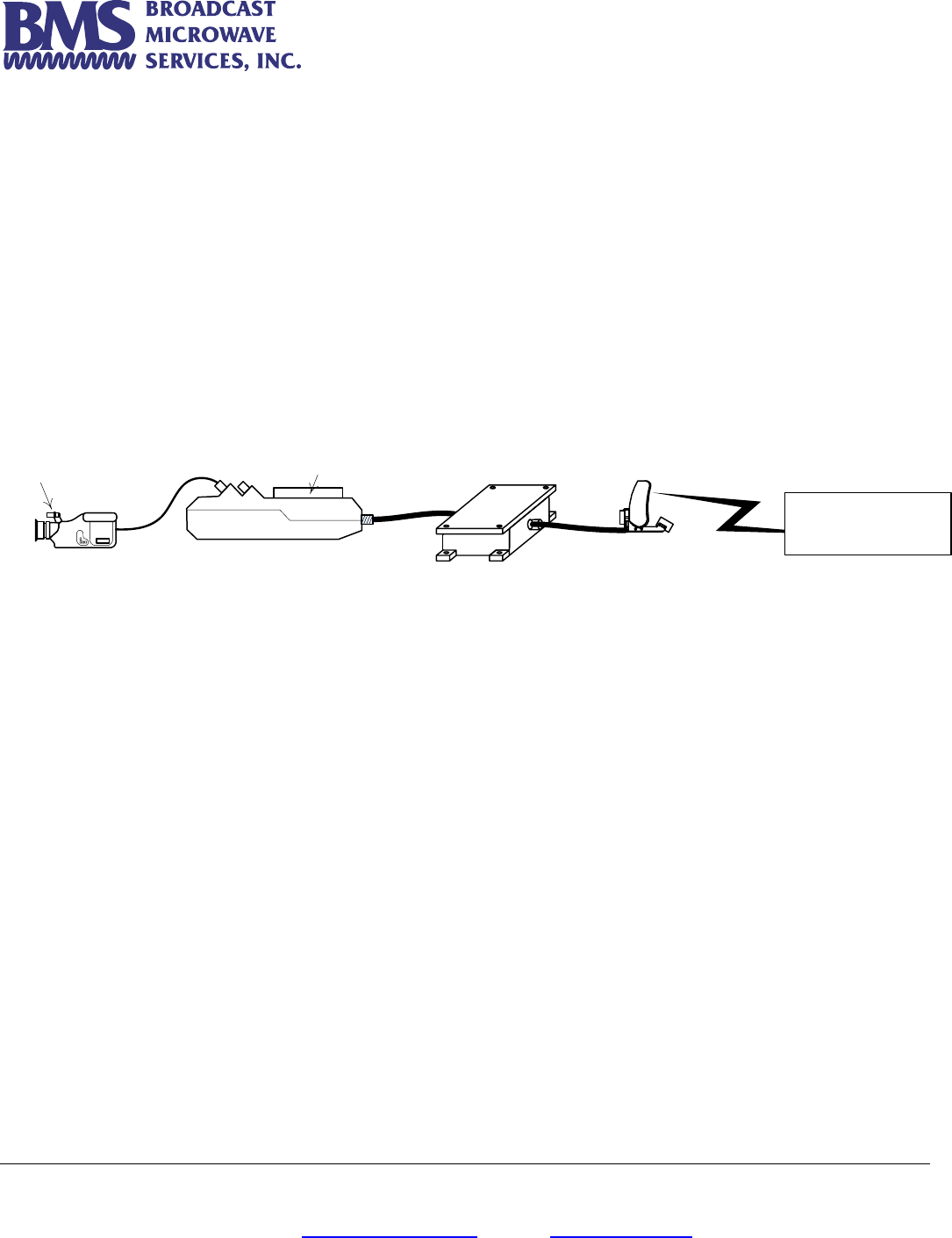
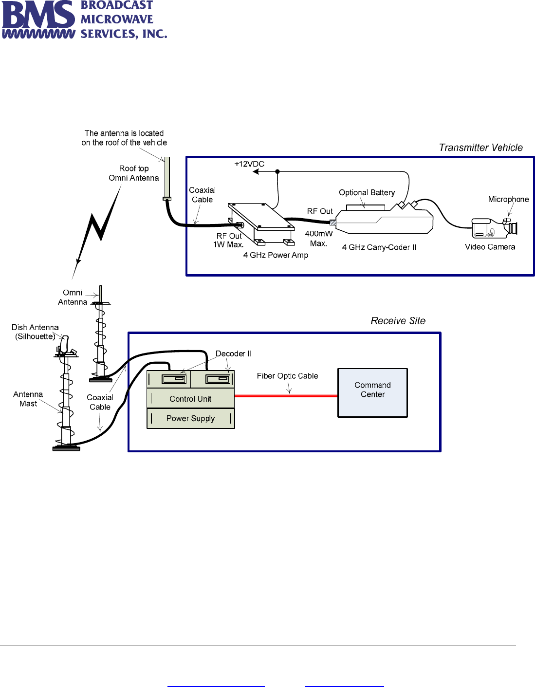
Typical system the 4GHz Carry-Coder II with Power Amplifier is shown in Figure 3.
Figure 3 Typical system of 4GHz Carry-Coder II with Power Amplifier
Mobile and Fixed Platforms
• The system of Figure 3 can demonstrate both mobile and fixed applications. The transmitter part including the Carry-Coder
II Transmitter, Power Amplifier and the video camera are all mounted inside a truck.
• An omni-directional antenna placed on the vehicle roof-top (without any obstruction) transmit uniformly in all azimuth
directions. This allows the mobile transmitter to communicate with the Receive Site while the vehicle is moving freely.
• In the Receive Site the omni-directional antenna on the mast will receive the transmitter signal without any need for
tracking.
• Because of low antenna gain (both on transmit and receive ends) the Power Amplifier will be crucial in order to boost the
transmitter power and ensure the minimum practical range.
• When the Transmitter Unit is stationary (i.e. the vehicle is stalled for a while) then the tracking dish antenna in the Receive
site will be able to track the transmitter and establish a line of site transmission. This is considered a fixed situation and the
high gain of the dish antenna will increase the minimum range. In the fixed platform the transmitter antenna can be
changed from omni to a tracking dish antenna.

Broadcast Microwave Services, Inc. – 12367 Crosthwaite Circle – Poway, CA 92064 10
Phone: 800-669-9667, 1-858-391-3050 - Fax: 1-858-391-3049
Email: support@bms-inc.com Web: www.bms-inc.com
• Regardless of the mobile and fixed applications the installation procedure for transmitter site will be similar as explained in
the following section:
Installation Procedure
The 4GHz Carry-Coder II with Power Amplifier can be installed inside a vehicle such as a truck. The symbolic diagram of the
installation is given in Figure 3. The installation procedure is as follows:
1. Install the omni-directional antenna on the vehicle roof-top using the brackets and instructions that are supplied in the
accessory kit.
2. Secure the Carry-Coder II transmitter and the Power Amplifier inside the truck. The two units may be one or 2 feet apart.
3. To ensure sufficient ventilation, at least 3” clearance is recommended from each side of the units.
• Using N-type coaxial cable (about 3 feet long) connect the output of the Carry-Coder II transmitter to the input of the Power
Amplifier.
• Using Coaxial cable and N to SMA adaptor, connect the output of the Power Amplifier to the SMA input port of the omni
antenna.
• Using the special power cords connect the Transmitter and the Power Amplifier to the 12V DC voltage.
• Connect the interface cables from the camera to the appropriate CARRY-CODER II connector(s).
• Using the supplied Remote Control Display, set the Transmitter frequency, power, modulation scheme …etc. as will be
explained in the next section.
Installing the Battery on the Carry-Coder II
The Carry-Coder II can be run by its own battery as well. The procedure for battery installation is as follows:
• Slide the battery in to the receptacle located underneath the CCII until it locks into place
• Connect the power cable coming from the battery connector socket to the CARRY-CODER II.
• Switch on the power for the camera and the CARRY-CODER II.
Broadcast Microwave Services, Inc. – 12367 Crosthwaite Circle – Poway, CA 92064 11
Phone: 800-669-9667, 1-858-391-3050 - Fax: 1-858-391-3049
Email: support@bms-inc.com Web: www.bms-inc.com
Controlling the CARRY-CODER II Transmitter
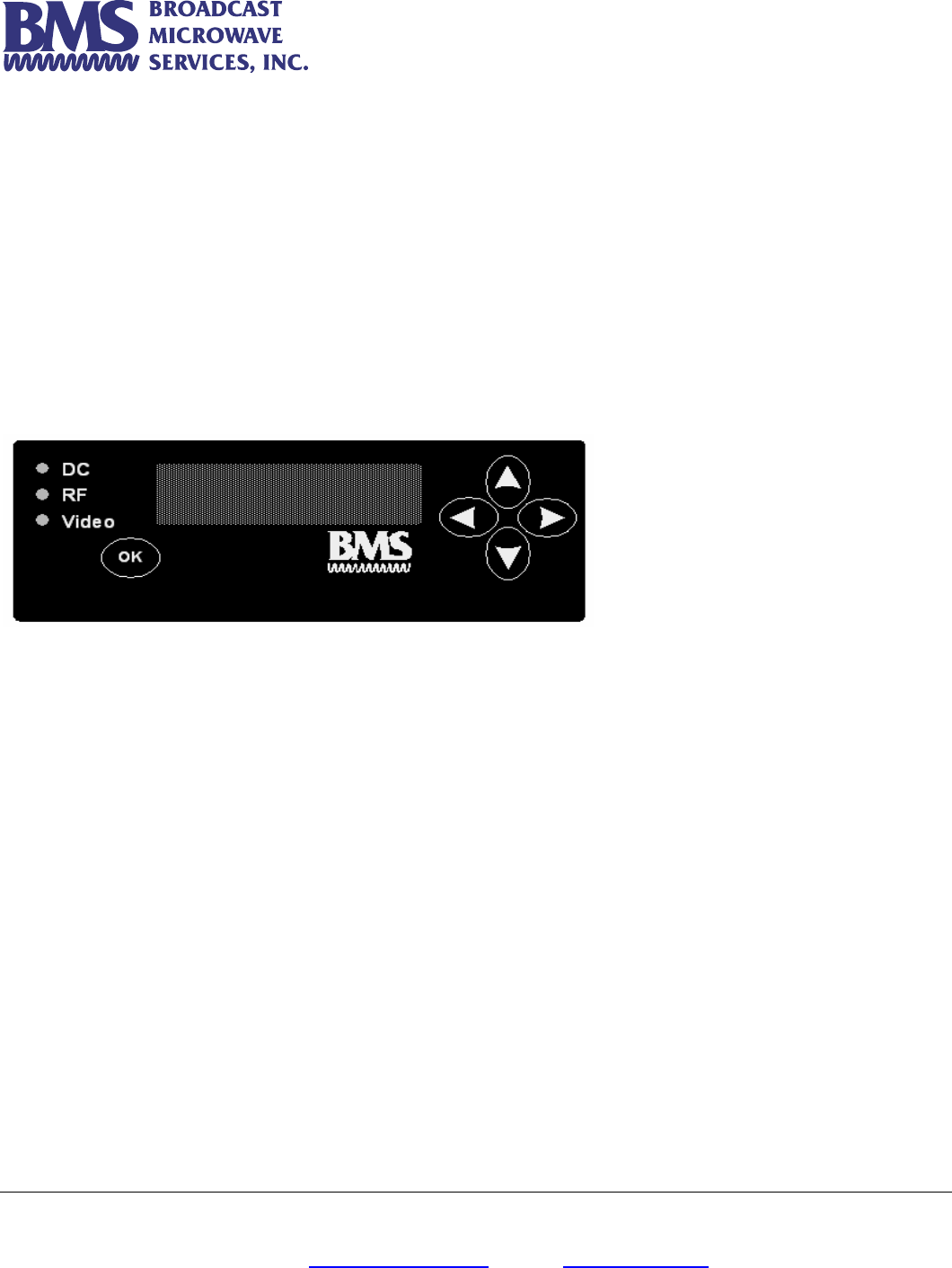
Control Unit Features
• The CARRY-CODER II control unit is designed for the convenience of the user.
• The control unit can be attached or disconnected at any time.
• Easily readable four line display.
• Operator navigation of menu with four intuitive directional buttons.
• Operational command entry using the <OK> button.
• Display includes status icons at right portion of top line.
• Text menu line one displays operating frequency.
• Text menu lines two and three are for system control functions.
• Text menu line four displays system status.
Transmitter Operating Configuration
When the CARRY-CODER II is powered up for the first time, the operator can easily review the operating parameters using the
control unit. Here is a listing of the parameters, in operating menu sequence.
• RF Output Operating Frequency
• RF Output Power (OFF LOW MID HIGH MAX).
• Transmission Mode Robustness (LOW MID HIGH).
• Recall Configuration (Presets 1 to 9).
• Save Configuration (Presets 1 to 9).
• Video Input (CVBS, YUV, ASI, SDI).
• Video Mode (PAL, NTSC).
• Audio Input (analog, AES, SDI).
• Audio Level Left
• Audio Level Right
• Data Port Baud Rate (1.2, 4.8, 9.6 Kbps)
• Encryption (OFF or PIN code entry).
• User Mode (NORMAL, EXPERT)
Broadcast Microwave Services, Inc. – 12367 Crosthwaite Circle – Poway, CA 92064 12
Phone: 800-669-9667, 1-858-391-3050 - Fax: 1-858-391-3049
Email: support@bms-inc.com Web: www.bms-inc.com
CARRY-CODER II Transmitter <EXPERT> Operating Mode Configuration
NOTE: Most users will operate the system in <NORMAL> mode. The <EXPERT> mode provides user control of certain DVB-T
parameter settings. Here is a listing of those parameters in operating menu sequence:
• Resolution (1/1, 3/4, 2/3, 1/2)
• GOP Structure (I, IP, IBP, IBBP, 422IBBP)
• GOP Length (6, 12, 18, 24)
• Constellation (QPSK, 16QAM, 64QAM)
• Guard Interval (1/32, 1/16, 1/8, 1/4)
• Code Rate (1/2, 2/3, 3/4, 5/6, 7/8)
Certain operating parameters are used on a repeated basis. These settings should be stored in memory as
Configuration Presets 2 through 9. This provides fast restoration of parameter settings that are used most often.
A good backup plan is to maintain commonly used parameter settings (i.e., high robustness and maximum power) in a
known configuration preset memory. If a problem occurs that won’t go away, a known good parameter setting can be
recalled from memory. This should help to resolve a problem. Another method is to adjust each parameter one by
one, beginning with changing the operating frequency, to ensure that the link is not being affected by another signal
on your selected operating frequency.
The <DEFAULT> option in the RECALL CONFIGURATION Menu will set all the parameters of the CCII to the factory
defaults.
OPERATING INSTRUCTIONS
Start-Up Indications
The CARRY-CODER starts with display showing the status of the system. During system initialization, the CARRY-CODER II goes
through self-test of its MPEG-2 encoder, COFDM modulator and RF sections. System initialization 10 seconds and will display as
follows:
BMS Inc. 4 GHz CarryCoder 2
Freq Agile 4940-4990 MHz
Software Ver. 2.01
Resetting /
At the completion of the initialization process, the display should look like this:
4965.00 MHz
FREQUENCY
4990.00 MHz
If the self-test finds that a sub-system does not respond correctly, a status message is displayed on the fourth line of the display.
For example, if the camera is not sending video to the transmitter, the display will include the appropriate message:
Broadcast Microwave Services, Inc. – 12367 Crosthwaite Circle – Poway, CA 92064 13
Phone: 800-669-9667, 1-858-391-3050 - Fax: 1-858-391-3049
Email: support@bms-inc.com Web: www.bms-inc.com
4965.00 MHz
FREQUENCY
4965.00 MHz
NO VIDEO
When the CARRY-CODER starts up, it is in the same condition as when it was powered down. This allows the user to
replace the battery with no need to touch the controls.
The CARRY-CODER II will not transmit with out video. If the System is powered up without video, the CARRY-
CODER II will automatically reboot once video input starts. The CARRY-CODER II will transmit with ASI.
Operator Menu Summary
When the control panel display shows normal system status (no Error or Warning status message) and if there is no operator use of
the control panel, the display goes dark to save battery life. Pressing any key on the control unit restores the display to show the
status of the system.
If there is a status message, the display will remain lit (will not go dark) until the problem is resolved.
The user menus can be accessed from the status screen by pressing any key. Then, the user can scroll the menus by pressing the
« Ç » and « È » keys.
After 30 seconds of keypad inactivity, the display automatically returns to the status screen.
Pressing the « Ç » and « È » keys simultaneously will cause the display to go to the status screen without having to
wait 30 seconds.
INPUT/OUTPUT CHARACTERISTICS
Composite Video (CVBS)
Type Composite Video Baseband Signal (CVBS)
Systems NTSC 525 lines / 60 Hz / Fsc = 3.58 MHz
PAL 625 lines / 50 Hz / Fsc = 4.43 MHz
Standard ITU-R BT 470-6
Impedance 75 Ohms
Component Video (YUV)
Type YUV (formerly Y / Pb / Pr)
Systems NTSC 525 lines / 60 Hz
PAL 625 lines / 50 Hz
Standard ITU-R BT 470-6
Impedance 75 Ohms
Broadcast Microwave Services, Inc. – 12367 Crosthwaite Circle – Poway, CA 92064 14
Phone: 800-669-9667, 1-858-391-3050 - Fax: 1-858-391-3049
Email: support@bms-inc.com Web: www.bms-inc.com
Analog Audio
Type Balanced Line
Channels 2 separate channels (Left and Right)
Nominal input level Adjustable from –10 dBu to +4 dBu (0 dBu = 775 mV rms)
Headroom 12 dB
Sampling frequency 48 kHz – 20 bits
Frequency response 30 Hz – 20 kHz (+/- 1dB)
Signal-to-Noise Ratio 65 dBA
Diaphony 60 dBA
Total Harmonic Distortion < 0.1 % @ 1 kHz
Impedance > 10 K ohms
If a low impedance input (600 Ohms) is required, the user can make a specific interface cable with 600 Ohm resistors
between the +/– lines of balanced audio conductors.
Data Input
Type RS-232
Possible Bitrates 9600, 4800 and 1200 bauds (selectable)
Format N, 8, 1 (1 start bit, 8 data bits, 1 stop bit, no parity)
Protocol None (no XON/XOFF)
For full bandwidth (100% continuous) data, set the decoder to a higher bit rate than the CCII to alleviate
losses due to asynchronous transmission.
Remote Control Port
Type RS232
Bit rate 9600 Bps
Format N, 8, 1 (1 start bit, 8 data bits, 1 stop bit, no parity)
Maximum cable length 100 m
Format and protocol Proprietary
It is recommended to use a shielded DB9 cable in order to increase reliability.
Broadcast Microwave Services, Inc. – 12367 Crosthwaite Circle – Poway, CA 92064 15
Phone: 800-669-9667, 1-858-391-3050 - Fax: 1-858-391-3049
Email: support@bms-inc.com Web: www.bms-inc.com
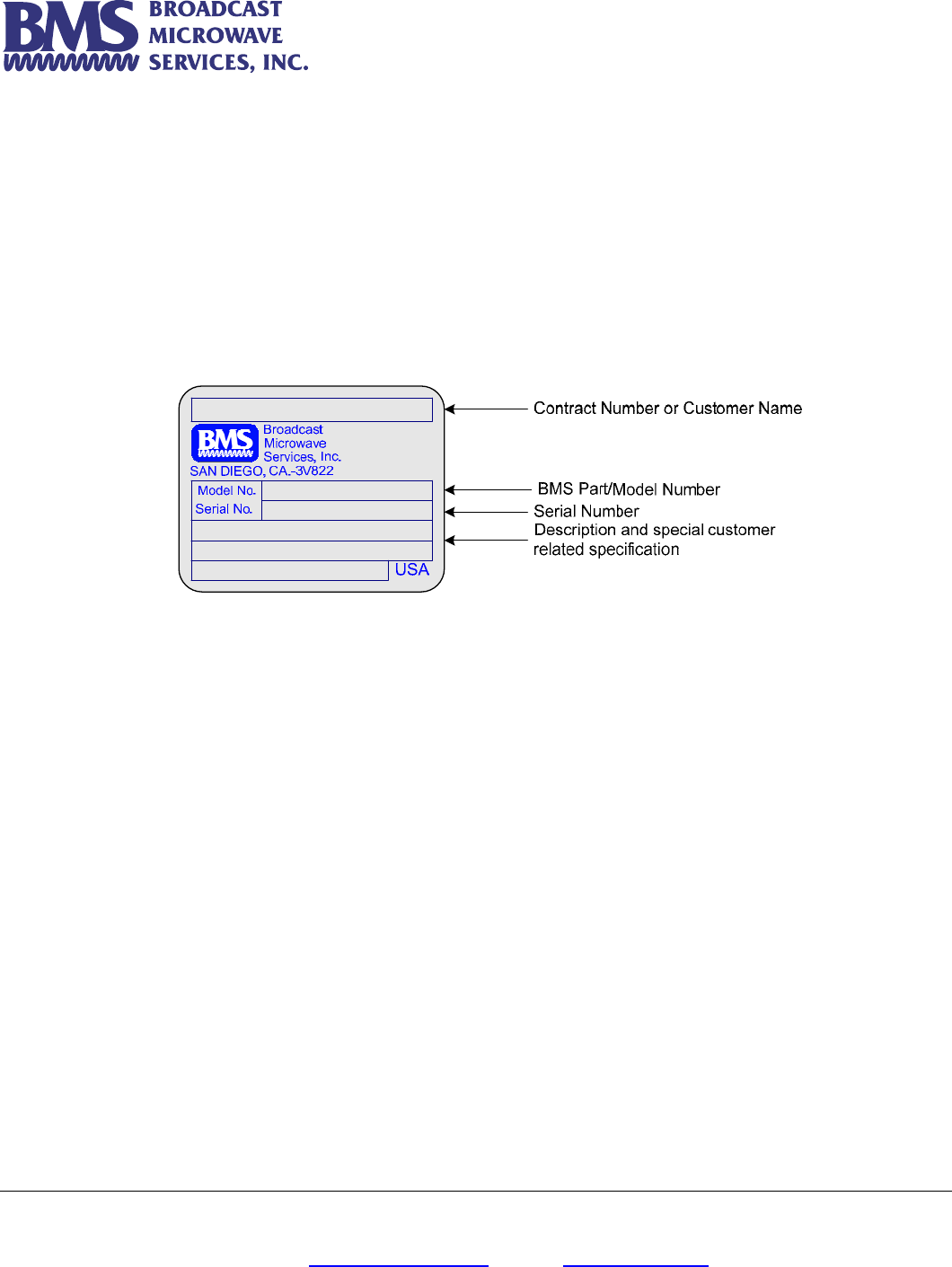
RF Output
The versions CARRY-CODER II are available for specific frequencies. Please refer to the CARRY-CODER II serial ID for
information on the operating frequency for the unit.
Never use the CARRY-CODER II without a 50 Ohms load or antenna properly connected to the RF output, since this
could damage the RF output stage.
The system can operate with several COFDM signals located on 8 MHz adjacent channels. When analog
transmissions are active in-band it is recommended to leave a free 8 MHz channel between COFDM signals and the
active analog signals.
Power Supply Input
The CARRY-CODER II can be powered either with a battery pack or through the 4 pin connector. This enables the use of an
external power source such as a battery belt or any appropriate power supply (+11 to 32 VDC @ 4A).
Frequency Range 4.94 – 4.99 GHz
Channel Bandwidth 6/7/8 MHz
Format COFDM (2K carriers)
Standard ETS 300 744 (DVB-T)
Output Power 10 mW, 25 mW, 100 mW and 400 mW
Shoulders at +/- 4.2 MHz > 30 dB for 1W
> 35 dB for 250 mW or less
Harmonic and Spurious < -60 dBc (DC to 6 GHz)
In-Band Ripple < +/- 1dB
Return Loss 18 dB (typical)
Impedance 50 Ohms
Connector N - Female
Broadcast Microwave Services, Inc. – 12367 Crosthwaite Circle – Poway, CA 92064 16
Phone: 800-669-9667, 1-858-391-3050 - Fax: 1-858-391-3049
Email: support@bms-inc.com Web: www.bms-inc.com
WARRANTY AND RETURN TO FACTORY
The CARRY-CODER II is warranted for a 2 years period, starting from delivery date.
In case of CARRY-CODER II failure, please use the following process:
• First have a look at the troubleshooting section of this manual in order to see if an immediate solution can be found.
• Before contacting BMS with questions about units, be sure to have the following information with you so we will be better
able to help you.
• Contact BMS technical support.
• If the technical support cannot solve the problem over the phone an RMA will be issued. Please send the unit at your
expense to BMS. Include all necessary explanations about the failure and mark the RMA number on the package and unit.
Please provide a PO to authorize a $350 evaluation fee if the failure is found to not a covered under warranty. Always use
original packing for transport.
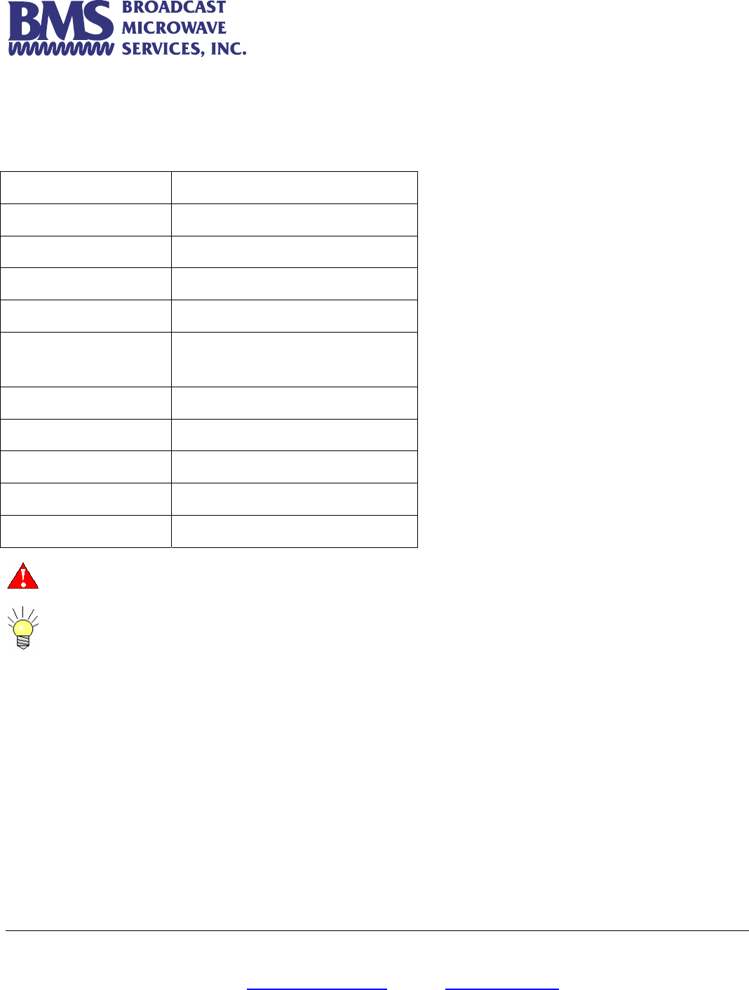
• Customer Name
• Contract Number
• BMS Model Number
• Serial Number
• Description of problem with as much detail as possible.
• Name of person to contact who might have further information
on the failure.
• Contact information such as phone number and/or email
address.
• Return Information
Broadcast Microwave Services, Inc. – 12367 Crosthwaite Circle – Poway, CA 92064 17
Phone: 800-669-9667, 1-858-391-3050 - Fax: 1-858-391-3049
Email: support@bms-inc.com Web: www.bms-inc.com
• Warranty position will be established upon receipt of inoperative equipment. If equipment is confirmed defective and is the
responsibility of BMS, repair action will be initiated immediately at no expense to the customer. When the malfunction is
determined to be the responsibility of the user, BMS will provide a quote to repair. Work to repair the unit will be initiated
after confirmation with the user’s buying authority.
• BMS will send back the unit at its expense via UPS ground.
There are no user serviceable parts inside the CARRY-CODER. Opening the device without prior authorization from
BMS will cause the warranty loss.
Broadcast Microwave Services, Inc. – 12367 Crosthwaite Circle – Poway, CA 92064 18
Phone: 800-669-9667, 1-858-391-3050 - Fax: 1-858-391-3049
Email: support@bms-inc.com Web: www.bms-inc.com
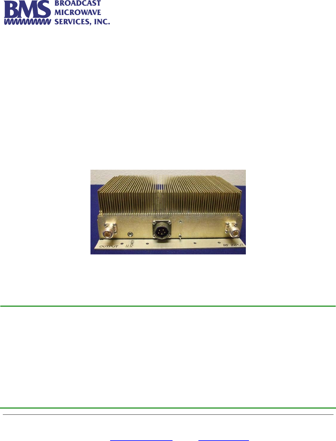
LINEAR POWER AMPLIFIER (BPA-1CC-4)
BPA-1CC-4 is a linear power amplifier with 1 watt maximum RF power and operating at Public
Safety band (4.94 – 4.99 GHz). This power amplifier is used in conjunction with 4 GHz Carry-Coder
II.
Application
Because the internal amplifier of the 4 GHz Carry-Coder II is only capable to provide 400 mW
max. RF power, an external amplifier is needed to boost the transmitter power in order to
compensate the path loss and ensure the acceptable Received Signal Level (RSL) at the
destination. The BPA-1CC-4 will increase the RF power to the maximum 1W, without adding
spurious and distortions to the transmitter output. The output of the power amplifier is directly
connected to the 4 GHz transmitting antenna.
BPA-1CC-4 Linear Power Amplifier
Specification:
Ch
Frequency 4.94 – 4.99 GHz
Output Power 1 Watt (30 dBm)
Input Voltage 28 VDC
Input Current 6.5 Amp
Input RF Power 400 mW (23 dBm) max.
Gain @ 23 dBm input 7 dB
Gain Flatness ± 0.5 dB Over 50 MHz
Gain vs. Temperature ± 1 dB Over Temperature
Operating Temperature -20° to +50°C
Storage Temperature 40° to +90°C
Dimensions 9.5” x 5” x 3”
Weight 5 lbs
RF Input Connector Type “N”
RF Output Connector Type “N” Isolator Protected

Broadcast Microwave Services, Inc. – 12367 Crosthwaite Circle – Poway, CA 92064 19
Phone: 800-669-9667, 1-858-391-3050 - Fax: 1-858-391-3049
Email: support@bms-inc.com Web: www.bms-inc.com
CONTACT INFORMATION
Broadcast Microwave Services, Inc.
Phone: 1.858.391.3050
Fax: 1.858.391.3049
Shipping address: 12367 Crosthwaite Circle
Dock 10
Poway, CA 92064
Website: http://www.bms-inc.com
Email: support@bms-inc.com
sales@bms-inc.com