Broadcast Warehouse TX25-50 FM Broadcast Transmitter type TX25-50 User Manual tx25500905 qxp
Broadcast Warehouse Limited FM Broadcast Transmitter type TX25-50 tx25500905 qxp
User Manual
Broadcast Warehouse
TX 25/50 FM BROADCAST TRANSMITTER
No part of this manual may be re-produced in any form without prior written permission from Broadcast Warehouse.
The information and specifications contained in this document is subject to change at any time without notice.
Copyright 2001 Broadcast Warehouse
For the latest contact information for Broadcast Warehouse please visit our website at,
www.broadcastwarehouse.com
Technical manual

TX25/50 FM Transmitter technical manual page 2
CONTENTS
1. Introduction
1.1 TX FM Transmitter
1.2 Safety
1.3 Front And Rear Panels
1.4 Control And Monitor LCD
2. Installation And Setup
2.1 Frequency Setup
2.2 R.F. Power Setup
2.3 Alarms
2.4 RS232 Control & Monitoring
2.41 RS232 Interface board
2.42 Windows application
2.43 Terminal control
2.5 Modes Of Operation
2.51 A guide to the jumpers
2.52 Multiplex / Broadband Input
2.53 Stereo With Limiters
2.54 Stereo With Limiters Disabled
2.55 Mono From Two Channels
2.56 Mono From One Channel
2.6 Other Setup Considerations
3. Technical data
3.1 Specifications
3.2 Circuit Description
3.3 Block Diagram
3.4 Internal Wiring / Case Overview
3.5 Schematics
3.51 LCD Control Section
3.52 Power Amplifier Section
3.53 All In One Exciter Section
3.531 Limiter Section
3.532 Coder Section
3.533 Exciter Section
3.6 Parts List
3.61 LCD Control board parts list
3.62 Power Amplifier board parts list
3.63 Combo board parts list

TX25/50 FM Transmitter technical manual page 3
Introduction
1.1 TX 25/50 FM TRANSMITTER
The Broadcast Warehouse TX 25/50 is a high specification FM broadcast transmitter. Its broadband “no-tune”
design allows 87.5-108 Mhz operation from internal direct reading rotary switches or the front panel LCD frequen-
cy control system if enabled. Digital PWM techniques provide an easily adjustable and accurate automatic level
controlled R.F. output of the Mos-Fet power amplifier stage.
R.F., Audio and other parameters are shown on the LCD graphics display. This display offers a very easy method
of transmitter parameter monitoring and a new level of ease for setup and installation, with metering accuracy nor-
mally only found on expensive test equipment. Local and remote personal computer control and metering are
achievable via the innovative dual method RS232 interface.
The FM modulator section employs a dual speed “virtual VFO” system for extremely low audio distortion and
excellent stereo performance.
A built in high specification stereo encoder provides crystal clear stereo sound and combined with the internal lim-
iter a fully compliant “plug and play” all in one low power broadcast transmitter.
For future compatibility all settings are switchable with on board jumpers. The stereo and/or limiter settings can be
switched in and out to suit the requirements of any external broadcast equipment you may have now and in the
future.
The lightweight universal mains input design ensures a high reliability efficient design compatabile with any mains
system in the world.

TX25/50 FM Transmitter technical manual page 4
Introduction
1.2 SAFETY
MAINS VOLTAGE.
This equipment operates from an AC power source of between 90 and 265 volts. There are hazardous
voltages present internally. PLEASE OBSERVE CAUTION WITH THE COVER REMOVED.
SWITCHED MODE POWER SUPPLY HAZARD
Please note that the power supply units in this equipment is of the switched mode variety and have lethal
voltages present internally. The switched mode supplies are universal input fully approved type. They are
non serviceable modules and should be fully replaced should they fail.
FUSES
Only use fuses with the specified voltage and current ratings as stated on the back panel. Failure to do so
may increase the risk of equipment failure, shock and fire hazard.
R.F.
The N type R.F. power output socket contains R.F. voltages which may burn or present a shock. Please
make sure that the equipment is connected to an adequately rated load or antenna system while in opera-
tion.
TOXIC HAZARD
This equipment includes R.F. components that may contain Beryllium oxide which is a highly toxic sub-
stance that could be hazardous to health if inhaled or ingested. Care should be taken when replacing or
discarding such devices. Seek expert advice from the manufacturer should you physically damage a device
that contains Berillyium Oxide.
The main R.F. output power transistor contains Beryllium oxide.
OTHER SAFETY CONSIDERATIONS
Do not operate this equipment in the presence of flammable gases, fumes or liquids
Do not expose this equipment to rain or water.
TX25/50 FM Transmitter technical manual page 5
Introduction
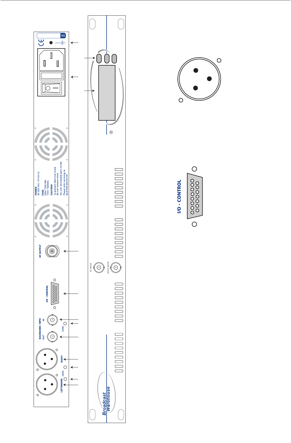
1.3 FRONT AND REAR PANELS
FUSE
1234567 8 9 11 13
1210
TX25/50 FM TRANSMITTER
1. Left audio input
2. Left Input gain
3. Right input gain
4. Right audio input
5. MPX output
6. MPX level control
7. MPX Input
8. Control / Logic
9. R.F. output
10 LCD display
11. Power socket
12. Up / Down frequency buttons
13. Chassis ground post.
Control / logic D-type pin out
Pin 1 PLL failure alarm (O/C)
Pin 2 Reserved
Pin 3 Reserved
Pin 4 R.F. failure alarm (O/C)
Pin 5 R.F. failure alarm (TTL)
Pin 6 Mod failure alarm (TTL)
Pin 7 PLL failure alarm (TTL)
Pin 8 R.F. Mute (Connect to GND for mute)
Pin 9 Mod failure alarm (O/C)
Pin 10 RS232 TXD
Pin 11 RS232 RXD
Pin 12 Reserved
Pin 13 Reserved
Pin 14 +18 VDC 200mA
Pin 15 GND
XLR Audio input connectors
Pin 1 Ground
Pin 2 Hot
Pin 3 Cold
3
21
15 14 13 12 11 10 9
8 7 6 5 4 3 2 1
Front panel:
R.F. MONITOR: -50dBC ( Not suitable for harmonic measurements )
MOD. MONITOR: ( Buffered multiplex, Nominally 3 V peak to peak for 75 KHz )
TX25/50 FM Transmitter technical manual page 6
Introduction
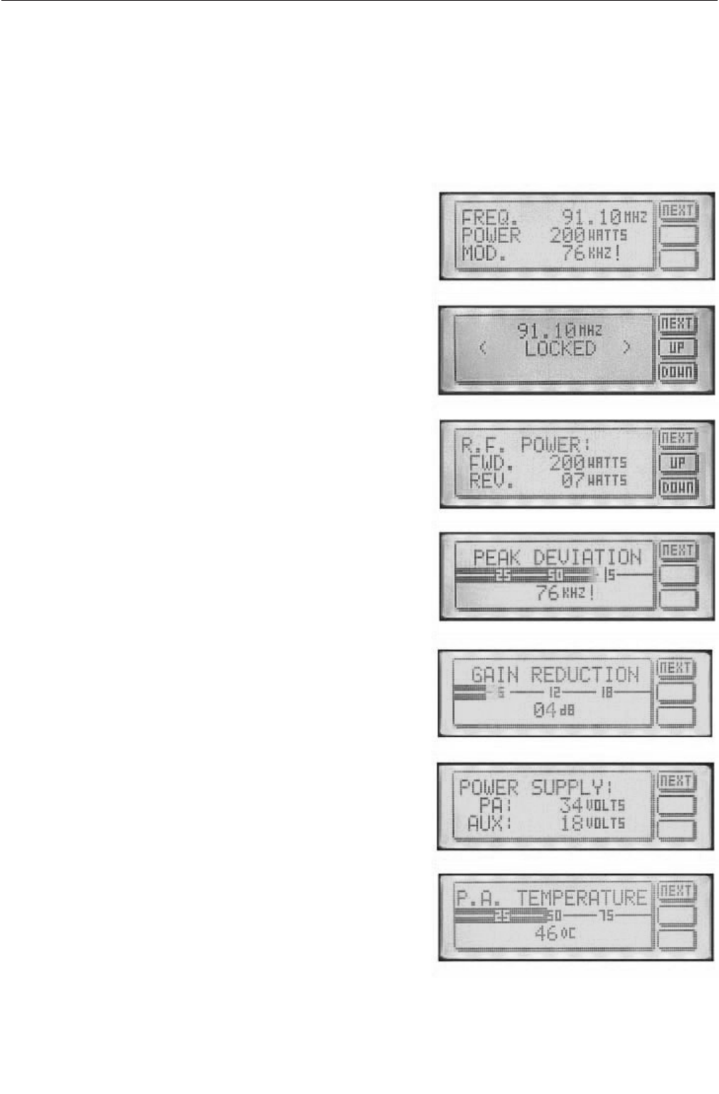
1.4 CONTROL AND MONITOR LCD
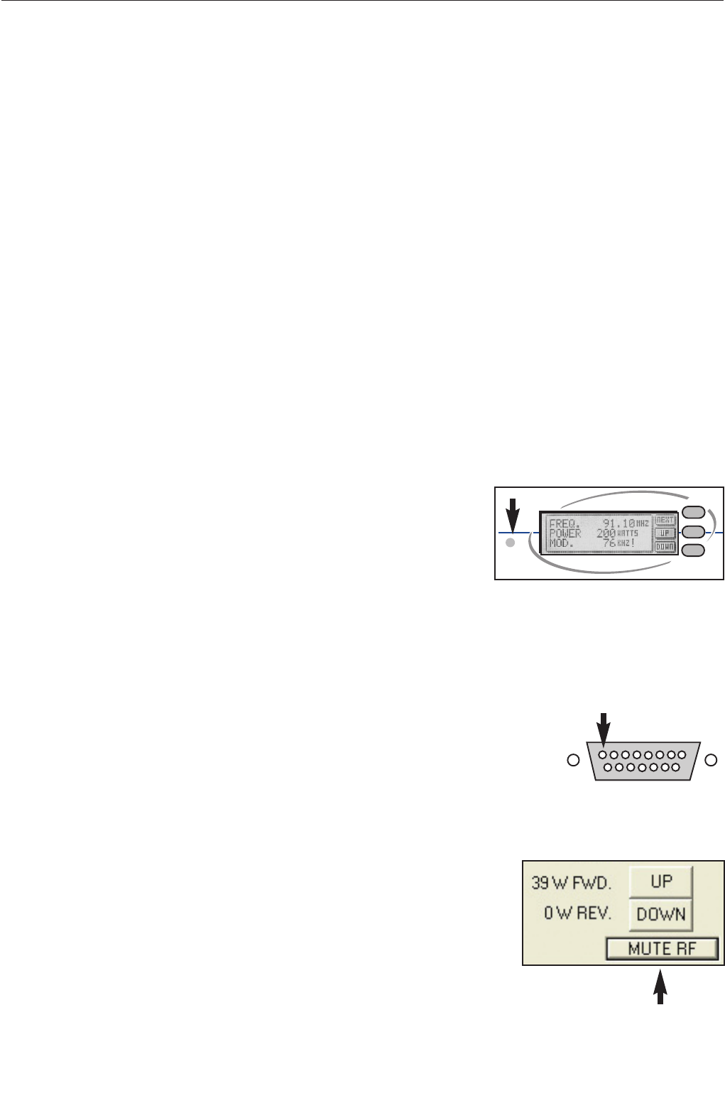
The front panel LCD graphics display has seven screens (shown below). These allow monitoring of the transmit-
ter’s R.F., audio and other parameters and the adjustment (if internally allowed) of the transmitter’s power and fre-
quency. You can move through the screens by pressing the NEXT button, which will display them in the following
order.
Main parameter screen.
This shows together the three most important transmitter
parameters. Frequency, R.F. output power and the peak
deviation.
Frequency display and control
This screen will display the frequency and PLL locked condi-
tion. The up and down buttons will allow 100 KHz frequency
steps from 87.5 to 108Mhz if the internal switches are set to
4440. If the frequency is set internally with the rotary switch-
es then the up / down buttons will give a ‘not allowed’ mes-
sage
R.F. power
The forward and reverse R.F. powers are displayed. The
up/down buttons will allow power control if internally allowed.
The maximum output power is governed by the maximum
power set adjustment (see R.F. pwr control section). If the
frequency is set internally with the rotary switches then the
up / down buttons will give a ‘not allowed’ message
Peak deviation
This display indicates the peak and average deviation. Peak
deviation is shown both numerically and as a moving single
pixel wide bar. Average deviation is shown with the solid
black bar. Over-deviation will display an exclamation ( ! )
Gain reduction
This display indicates the amount of gain reduction of the
internal audio limiter. The range is 0 to 24 decibels of gain
reduction.
Power supply
Power amplifier voltage is shown together with the transmit-
ters secondary supply that feeds the exciter section. The
power amplifier voltage will vary depending on set output
power and the presence of any fault conditions which also
cut the voltage back and with it the R.F. output.
P.A. temperature
This display indicates the temperature of the heatsink that
the R.F. power transistor is bolted to. The normal operating
temperature range is 40-60 degrees at full R.F. power out-
put.
TX25/50 FM Transmitter technical manual page 7
Installation and setup
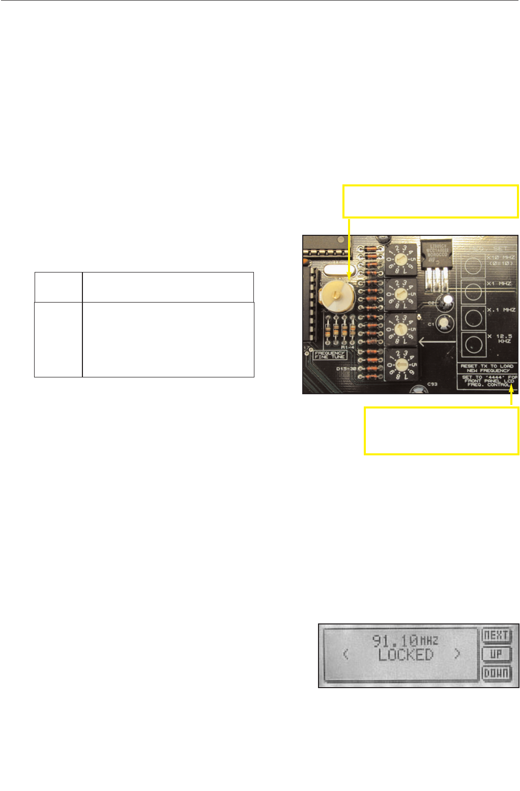
2.1 FREQUENCY SETUP
The Frequency can be set on the transmitter in one of two ways:
1. From internal direct reading decimal switches on the main board
2. From the front panel LCD display and front panel buttons.
Many radio regulatory bodies stipulate that the transmitters parameters including the frequency must not be easily
changed from the front panel. To meet this requirement you will need to set the frequency internally with the dial
switches.
The switches have a silkscreen diagram next to them on the board (see diagram below) clearly indicating what
each switch represents.
The top dial switch represents the value selected x 10 Mhz with the exception of ‘0’ which represents 10 so when
selected would equal 100 Mhz.
The second dial switch represents the value selected x 1 Mhz.
The third dial switch represent the value selected x .1 Mhz (100 KHz)
The bottom switch represents the value selected x .0125 Mhz (12.5 KHz)
For example:
FREQ SWITCHES (MHZ)
X10 X1 X.1 X.0125
87.90 ‘8’ ‘7’ ‘9’ ‘0’
98.75 ‘9’ ‘8’ ‘7’ ‘4’
100.00 ‘0’ ‘0’ ‘0’ ‘0’
104.225 ‘0’ ‘4’ ‘2’ ‘2’
108.00 ‘0’ ‘8’ ‘0’ ‘0’
As you can see, the switches directly read the frequency with the exception of
frequencies above 100 Mhz, where the top switch being set at ‘0’ represents
‘10’. The X0.125 ‘offset’ switch is only used when you want to provide a shift to
the carrier of between 12.5 KHz and 112.5 KHz. Note that setting the switch
on 8 or 9 will have the same effect as setting the previous switch (100 KHz) 1
position higher, as 8 represents 100 KHz on the 12.5 KHz switch. 8 x 0.125MHz = 0.1MHz = 100KHz
The LCD display on the front panel will display the frequency that you have set on the internal switches. If you try
to adjust the frequency with the front panel up / down buttons you will get a ‘ NOT ALLOWED ‘ message appear-
ing on the LCD display. This protects against unauthorized front panel frequency changes when the frequency
has been set internally with the dial switches.
The TX will load the switch values at power up. You will need to remove the mains power to the transmitter
and then reapply it if you want to change the frequency by using the direct reading switches
LCD front panel frequency selection.
If you want to control the frequency from the front panel LCD control
system you will need to set the internal switches to 4440. The trans-
mitter will pass frequency control to the LCD control system and the
frequency can be moved up and down by pressing the NEXT button
until the frequency menu is displayed. The other two buttons control
the UP and DOWN frequency selection. PLL lock status is also dis-
played on this screen.
The LCD readout will only display frequencies in 100Khz steps. Any frequency offsets derived from the
internal 12.5KHz offset switch will not show on the LCD. Consult a frequency counter if using offsets.
Note that some pcb’s have “set to 4444 for
front panel LCD control”. This is an error that
will cause a +50KHz offset to the frequency
set on the LCD screen. Please set to 4440
unless you specifically want the offset.
Frequency selection switches on main board
Fine frequency control. Do not adjust unless you
know what you are doing. Consult advanced setup
section of manual for more information.
TX25/50 FM Transmitter technical manual page 8
Installation and setup
2.2 R.F. POWER SETUP
The R.F. power output from the transmitter can be controlled by an analogue potentiometer (POT) or from the
front panel LCD screen or a combination of both.
ANALOGUE POWER CONTROL
If the frequency is set internally with the dial switches you will not be able to adjust the power from the LCD
screen. This is to comply with regulatory body’s that stipulate that the transmitter is not to have it’s parameters
adjustable from the front panel. In this case you must use the maximum power set control to set the transmitters
power. This control will give the full power range adjustment.
If the transmitter has been internally set to 4440 with the dial switches then you can also control the power from
the LCD screen’s R.F. power menu’s up and down buttons. A “not allowed” message will be displayed to the user
if the dial switches are not set to 4440
RS232 power control will over-ride the power control restrictions caused by having the frequency set
internally (not set to 4440).
DIGITAL POWER CONTROL
When the power is to be controlled from the front panel the max power set POT takes on a new role of setting the
maximum power of the transmitter. If you want the LCD screen to have full power range control of the transmitter
you will need to ensure that the max power set control is at maximum power. Otherwise your control range may
be limited. This feature enables you to limit the transmitters maximum power to a fixed level but to still allow the
LCD screen to provide adjustment of the R.F. power down from that maximum power set point. This can be desir-
able in transmitter hire situations where you wish to govern the maximum
output to a fixed level but to allow the customer (hirer of the transmitter) to
run the power of the transmitter at a lower level if they so decide.
The maximum power set is positioned to the lower left of the LCD screen on
some models, other models may not have the hole in the front panel and you
will need to remove the lid of the transmitter to access the adjustment which will be in the same position but on
the other side of the PCB. You will need a small ‘tweaker style’ flathead screwdriver to adjust the pot. This control
is quite delicate so try to not be too heavy handed in it’s adjustment.
Please note that the VSWR and temperature protection circuitry will turn back the R.F. power if a fault con-
dition exists. Make sure that you have a good VSWR (low reverse power reading) before setting the R.F.
power as the removal of a fault condition may cause the R.F. power to increase.
RF POWER MUTE (analogue)
There is a pin (8) on the back panel D-type that can be pulled low to mute the
transmitters RF power. The RS232 interface board also has a connection to mute
the RF this way. Consult the RS232 section of this manual for more information.
RF POWER MUTE (digital/RS232)
The transmitters RF power output can be muted via the RS232 control system.
Terminal software can mute/unmute the RF power with the ‘o’ and ‘f’ commands
respectively.
The windows application has a button that can toggle the RF output of the trans-
mitter.
please consult the RS232 section of this manual for more information on controlling the transmitter remotely.

TX25/50 FM Transmitter technical manual page 9
Installation and setup
2.3 ALARMS
The Transmitter has three alarms that can alert the broadcaster if one of the following fails:
R.F. POWER, PLL LOCK, MODULATION
The alarms when set are available on the back panel D-type. Each alarm has an Open collector and a TTL level
contact on the D-type. The alarm induced active open collectors can pull down any external signals and the TTL
outputs will provide a 5 Volt indication. The alarm is also visible if any RS232 monitoring is employed.
For the alarms to function correctly the transmitter must be left on the default menu screen. This is the screen that
displays frequency, R.F. power and peak deviation. To ensure that the alarm system functions correctly the trans-
mitter will return to the default menu screen if the LCD is left on another menu screen for more than 5 minutes.
R.F. POWER.
The R.F. power alarm will be set if the R.F. power falls below a threshold level during normal operation.
This threshold is set below the normal operating lowest wattage available from the transmitter. If you
require a different setting for the alarm, contact our tech dept. The alarm will only be set if the fault condi-
tion exists for sixty seconds or more. You will need to reset the transmitter to clear the alarm/s.( also see
RS232)
PLL LOCK.
The PLL lock alarm will be set if the transmitters falls out of frequency lock during normal operation. The
alarm will only be set if the fault condition exists for sixty seconds or more. You will need to reset the trans-
mitter to clear the alarm/s.( also see RS232)
MODULATION FAILURE.
The Modulation failure alarm will be set if during normal operation the peak deviation of the transmitter
drops and remains below 16 KHz. The 16 KHz alarm level allows the alarm to be set if the audio feed to
the transmitter fails even if the stereo pilot internal to the transmitter is still modulating the transmitter. The
alarm will only be set if the fault condition exists for sixty seconds or more. You will need to reset the trans-
mitter to clear the alarm/s.( also see RS232)
MORE INFO ON ALARMS
The three alarms are available on the back panel D-type connector. The pin-outs are shown on the rear
panel diagram. The three alarms are available as TTL level and as open collector outputs. The TTL level
outputs are active high in the event of an alarm. The open collector outputs are ON in the event of an
alarm and will pull down any external levels. The open collectors can sink 100mA MAX with an absolute
maximum switched voltage of 25 volts.
The D-type connector can also supply 18 volts at 200mA that can be used for pull-ups on the open collector
alarm outputs and for your own external switching circuitry. Broadcast warehouse can also supply custom
plug in PCB’s for the D-type that will allow N+1 control. Two transmitters can be installed in the same rack
and in the event of an alarm being set the external PCB will switch between the main and standby trans-
mitters and if needed switch a coaxial relay.
The RS232 interface provides the ability to reset the alarms. More info is found in the RS232 section of
manual.
Broadcast warehouse can also customise the alarm / fault software to meet the requirements of major
broadcasters and networks. More information on this and other custom features can be obtained from our
technical department.
TX25/50 FM Transmitter technical manual page 10
Installation and setup
2.4 RS232 CONTROL AND MONITORING
The TX range of transmitters can be monitored or controlled from a personal computer either locally or remotely.
The Transmitters can “chat” either by a windows application or via a standard serial terminal program. The win-
dows application is the more versatile option and is to be preferred but the ability to use a terminal program can
prove useful in the absence of the windows application or a computer that runs windows.
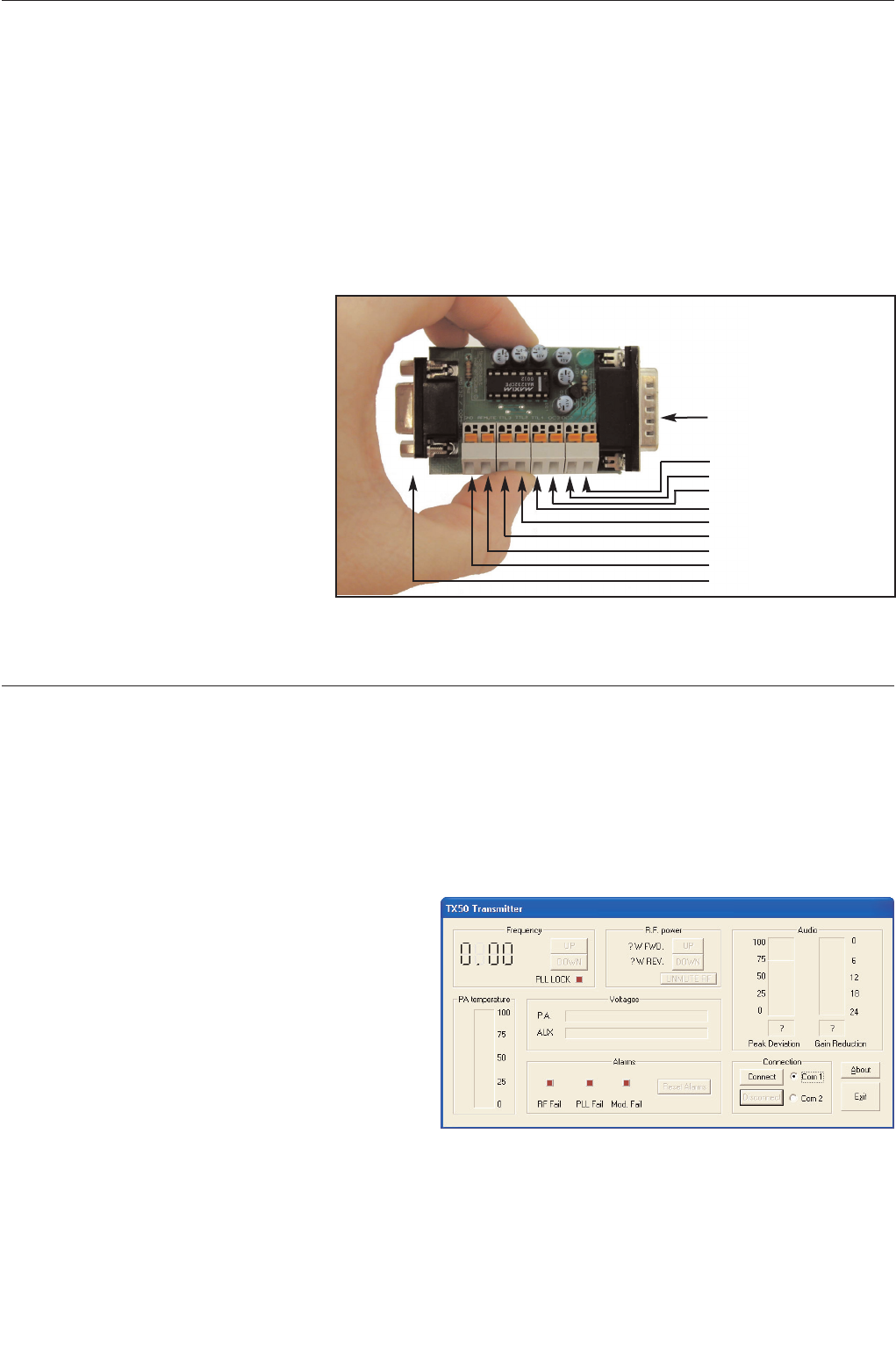
2.41 RS232 interface board
To connect your TX series transmitter to your serial cable you will need the optional BW TX series RS232 inter-
face board (shown). This board provides
the level conversion required for RS232.
The board also provides an interface to
the various control and alarm signals
present on the transmitters 15 way D-
type connector. For further details of the
alarms please see the back panel con-
nection page of this manual.
The Interface board will push into the
transmitters D-type connector and you
can then break out your other signals via
the push/snap terminals. a 9 way serial
lead from your computer can be plugged
into the expansion boards 9 way D-type
socket..
The above item is an optional extra and
is available from broadcast warehouse and it’s distributors
2.42 Windows application (TXCTRL.EXE)
The latest version of TXCTRL.EXE can be downloaded from...
http://www.broadcastwarehouse.com/downloads
Installation
The windows application is a single file executable that
can be simply run by clicking on it’s ICON. The pro-
gram doesn’t require a setup program and can simply
be copied to the desktop and run as neccessary.
Setup and connection.
Once opened the application will resemble the picture
to the right.
Connect a serial cable between the RS232 board that plugs into the i-o D-type on the rear of the transmitter and
one of your computers COM ports. If you are using a codec or other device then you may be able to connect that
device in line to act as part of the serial link.
The application can connect to either COM port 1 or 2 on the computer that is running the application. Select the
TRANSMITTER
O/C Mod fail
O/C PLL fail
O/C R.F. fail
TTL R.F. fail
TTL Mod fail
TTL PLL fail
R.F. MUTE (PULL LOW FOR MUTE)
GND
COMPUTER
TX SERIES RS232 INTERFACE BOARD
TXCTRL startup screen
TX25/50 FM Transmitter technical manual page 11
Installation and setup
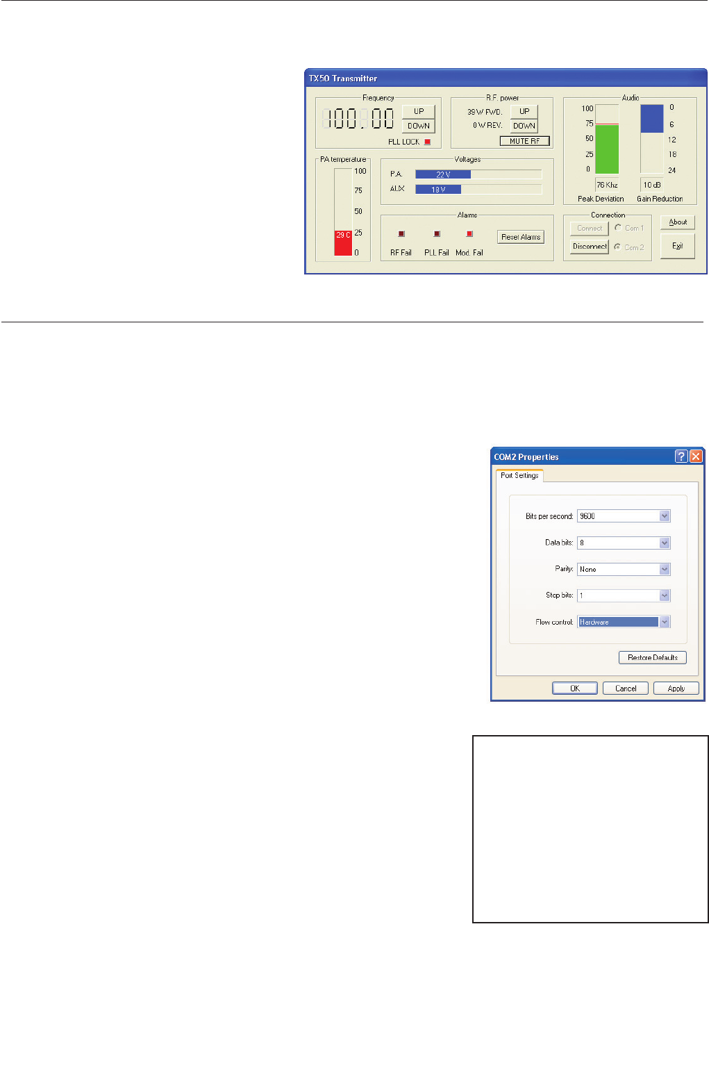
COM port you want to use and then click the Connect button.
If the application is able to connect to the trans-
mitter then you will be presented with a screen
similar to the one on the right. Once connected
you should be able to view all the parameters of
the transmitter as well as being able to mute the
R.F., change the frequency, change the R.F.
power and reset any alarm flags that have been
set.
2.43 Terminal control of the transmitter
Installation
Please see the instructions for your terminal software package to find out how
to connect to a remote serial device. The transmitter is internally set to com-
municate at 9600 bps, no parity with 1 stop bit. This is commonly known as
9600 8N1. If your using windows then you can use the pre bundled terminal
program “hyper-terminal”. This is located in the accessories/communications
folder accessible from the start menu. Select direct to com port x where x is
the com port that the transmitter is connected to. You will be presented with a
dialog box like the one shown to the right. Select 9600, 8 , none ,1 with hard-
ware flow control and then click ok.
If you are using another terminal program then you may need to consult the
documentation for that software but it should be pretty much straight forward.
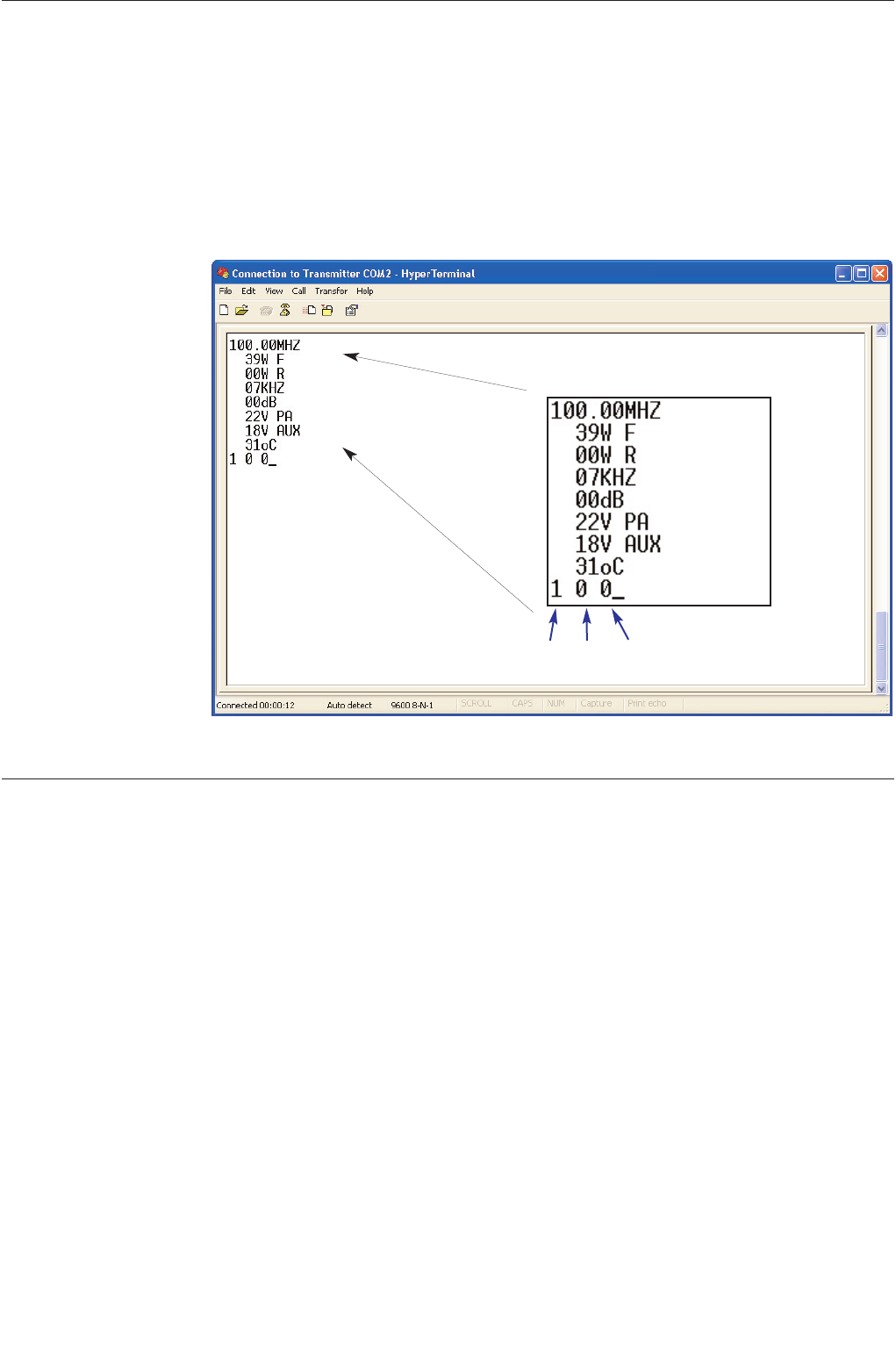
Operation
The transmitter will respond to certain key presses and each one has a certain function. See the list below for
details of what key to press for each function.
The most important key press is the ‘enter’ key. This will need to be
pushed as soon as you connect to the transmitter so you can get the trans-
mitter to refresh your terminal window with the transmitters status and
parameters. (shown on next page)
The transmitter won’t respond to any of the other key presses until it
detects the ‘enter’ key is pressed. Once the enter key is pressed the trans-
mitter will listen out for other key presses for 60 seconds. This Initial ‘enter’
key validation and time window is a safety feature to prevent the transmit-
ter from detecting an erroneous key press such as r.f. mute and causing a
service affecting problem.
After performing a function you may need to press the ‘enter’ key to see a response to your function. For exam-
ple, If you pressed ‘o’ for R.F. Mute you would not see the effect of the R.F. power change until you refreshed the
screen again because the terminal window would still be showing the transmitters R.F. power from the previous
‘enter’ (screen refresh) command, prior to you performing the R.F. mute command.
‘1’ Frequency up
‘2’ Frequency down
‘3’ R.F. power up
‘4’ R.F. power down
‘5’ reserved
‘6’ Reset alarms (all to 0 / off)
‘o’ Mute R.F.
‘f’ Unmute R.F.
‘ENTER’ Refresh screen
Hyper Terminal connection
TXCTRL when connected
TX25/50 FM Transmitter technical manual page 12
Installation and setup
The frequency change key’s will perform an automatic screen refresh on there execution but the other keys will
require a refresh command to be sent to the transmitter for you to visibly be able to see the effect of your com-
mand. In some circumstances you may need to press the refresh screen key several times in order to see what’s
happening. Take the R.F. mute function again as an example. You press the R.F. mute key (‘o’) and then press
refresh screen key (‘ENTER’) to get a status update. The transmitters power control circuitry may not have had
time to turn the r.f. power down into full R.F. mute by the time it has sent back to you the status requested by the
refresh screen command. It does no harm to wait a second or two before asking for a refresh screen or by asking
for several refresh screens by pressing the ‘enter’ key a few times in succession.
FREQUENCY
FWD R.F. PWR
REV R.F. PWR
PEAK MOD
LIMITER G.R.
P.A. VOLTS
AUX VOLTS
P.A. TEMP
ALARMS
R.F. FAIL PLL FAIL MOD FAIL
1=alarm set, 0=no alarm set
Hyper Terminal window
TX25/50 FM Transmitter technical manual page 13
Installation and setup
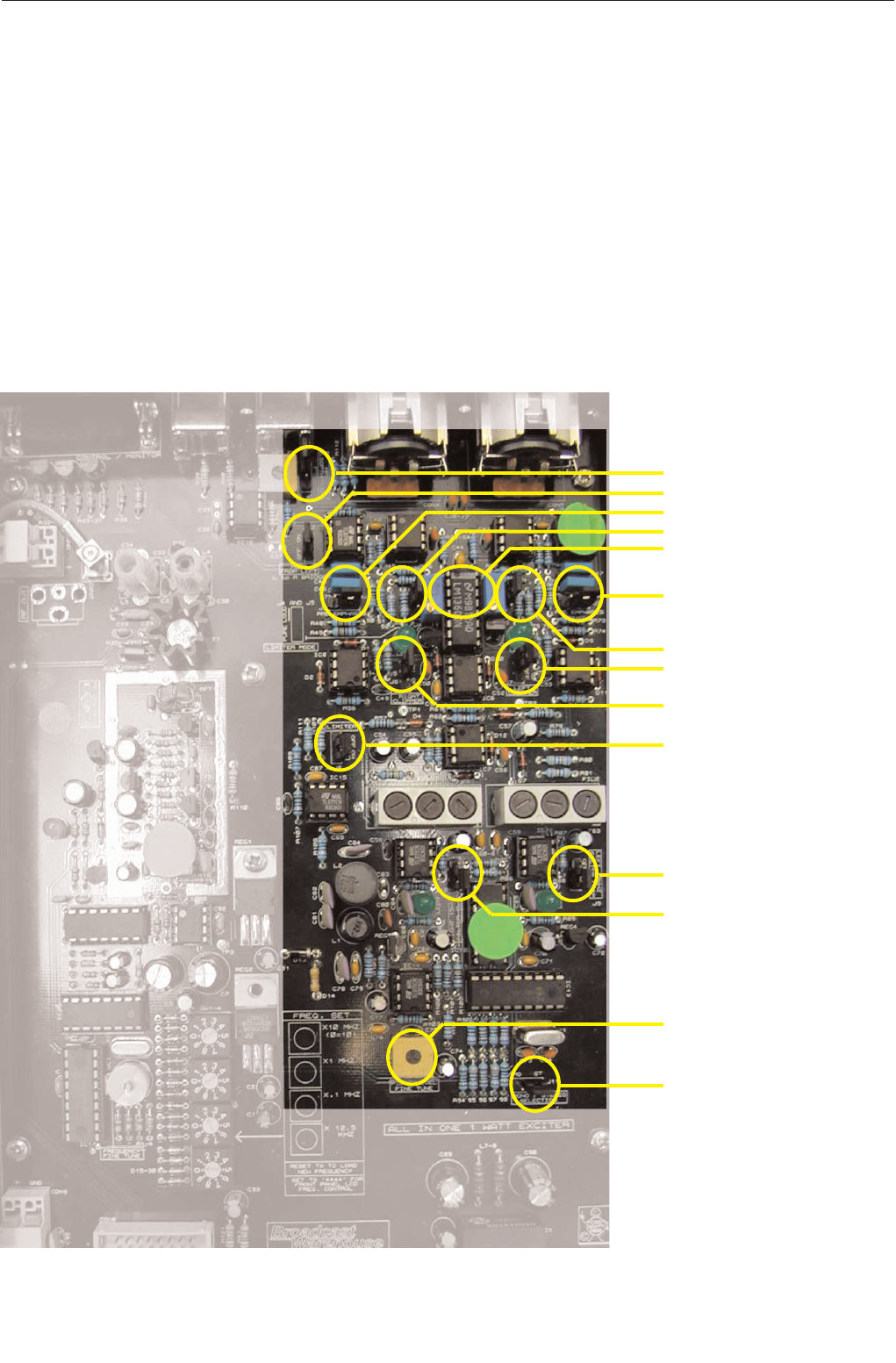
J1 MPX loopthrough
J12 Mono from left
J2 Right pre-emphasis
J4 Right Loud/Clarity
VR3-4 Limiter offset trim
J3 Left Pre-emphasis
J5 Left Loud/Clarity
J7 Left Lim. Clipper
J6 Right Lim. Clipper
J8 Limiter On/Off
J9 Left filter Clipper
J10 Right filter Clipper
VR6 Pilot level control
J11 Pilot On/Off (stereo)
2.5 MODES OF OPERATION
The transmitter is fully configurable and can be set up to support various modes of operation. The mode of opera-
tion is set by the configuration of the internal jumpers.
This chapter provides a guide to the various jumpers, followed by a brief description of the main modes of opera-
tion. The advanced setup procedure pages that follow provide a little more information on each mode as well as
providing some information on setting the equipment up accurately if you have access to some test equipment.
2.51 A guide to the jumpers
Main combo board

TX25/50 FM Transmitter technical manual page 14
Installation and setup
There are altogether twelve jumpers on the board which can be set - at the time of installation - to establish the way
the board operates.
The board leaves the factory with default settings which should be suitable for most locations and requirements.
Nevertheless, it is worth familiarizing yourself with all the options available, and checking that the settings are appro-
priate, as part of the installation process.
Jumper 1: MPX loopthrough
The default position is ON.
This is where you want the audio left and right XLR sockets on the back of the board to be the signal source,
duly limited and stereo coded internally. Only when you want to use the rear BNC socket for a complete mul-
tiplex (MPX) input for the broadcast should you change the position of this link.
If the link is in the OFF position, only signals from an external coder or processor will be accepted, unless the
internal coder has been ‘loop-throughed’ (see later).
Jumpers 2 and 3: Pre-emphasis 0 / 50 / 75uS
The default position is 50 uS (75 US/Japan).
What is pre-emphasis?
Pre-emphasis is the treble boost that must be applied to all FM broadcasts to compensate for the treble cut
(de-emphasis) present in every receiver. The aim of this process is to reduce noise in the broadcast path with-
out degrading the audio.
The precise nature of the treble boost is defined by a time-constant in microseconds, which describes the
resistor/capacitor network that will produce the appropriate 6dB per octave treble boost curve.
There are two different standards in use worldwide.
In Europe and Africa, the standard is normally 50uS. This represents a lift of about 3dB at 3 KHz, and
10dB at 10 KHz. In the Americas, and in Japan, more boost is in use with a network of 75uS, about 3dB
up at 2 KHz.
Jumpers 2 & 3 may either link the 50uS pins, the 75uS pins, or not link any pins, but be fixed to just one of
them for safekeeping, producing no pre-emphasis - ‘0’.
The effects of pre-emphasis
The absence of any pre-emphasis will result in a broadcast sounding noticeably lacking in treble. Applying
50uS pre-emphasis will correct the situation in European receivers (75uS in US/Japan). If you apply 75uS
pre-emphasis when 50 is called for, the received sound will have some 3dB shelved treble boost above 3KHz.
This is undesirable. Conversely, if you only apply 50 where 75 is required, there will be 3dB treble loss, which
is also undesirable. You should not have to change the pre-emphasis setting from 50 to 75 or back unless
you are relocating the installation abroad where the standard is different.
However, whenever pre-emphasis is deliberately applied to your audio at some point before it enters the XLR
sockets on the back of the board, by an external processor for example, then you must set the pre-emphasis
to ‘0’, because pre-emphasis must only be applied once. Double pre-emphasis must be avoided because it
will make a signal sound far too bright and toppy.
Both Jumper 2 and Jumper 3 should be in the same position at all times because both left and right audio
channels should have the same treatment. These jumpers do not affect the operation of the board when
external MPX is used with Jumper 1 off.
Jumpers 4 and 5: Limiter loud/pure
The default position is ‘Loud’ (hard limiting).

TX25/50 FM Transmitter technical manual page 15
Installation and setup
This option affects the character of the sound passing through the limiters inside the board. The sound can
be either (a) processed to be competitively loud, with some sacrifice in fidelity (hard limiting, the Loud posi-
tion) or (b) treated more gently, with high fidelity, but some loss in volume (soft limiting, the Pure position).
It’s instructive to listen to and compare the options while passing a representative selection of typical pro-
gramme material through the board. This will help you establish which sound you prefer.
As before, both jumpers 4 and 5 should always be in the same position. These jumpers, like all the following
ones, do not affect the operation of the board when external MPX is used with Jumper 1 off.
Jumpers 6 and 7: Limiter clippers on/off
The default position for these jumpers is ON.
If they are to be switched off when external audio processing is used, careful monitoring of deviation is rec-
ommended. The 15 KHz post-filter clippers must be switched off at the same time (J9/10).
These jumpers control the clippers applied to the signal after the limiter but before the 15KHz low-pass filters
on the way into the stereo coder. Again, these jumpers work as a pair and do not affect external MPX inputs.
Jumper 8: Limiter on/off
The default position for this jumper is ON, i.e. limiter active.
If you are using a pre-processed and limited signal and do not want the additional protection of the internal
limiters, their action can be disabled by putting Jumper 8 in the OFF position. This one jumper controls both
channels, because the gain-reduction control voltage (which this jumper disables) is common to left and right.
Even with the limiter disabled you may still wish to use the pre-filter clippers (J6/7) and post-filter clippers (see
below, J9/10) for protection. Always observe the deviation produced very carefully for excesses above 75
KHz if you ever remove the action of the limiter or clippers.
Jumpers 9 and 10: 15KHz filter clippers on/off
The default position for these clippers, placed after the 15KHz filters on the input to the coder, is ON.
These clippers protect against over-deviation caused by signals which ‘ring’ in the 15KHz filter, even after hav-
ing been caught by the clipper before the filter. With certain pre-processed and filtered inputs, however, they
may be switched out of circuit. But keep a close eye on the deviation.
Don’t have these clippers switched on unless you also have the limiter clippers active. Otherwise, your sig-
nal could go out of specification.
These jumpers work as a pair and don’t affect external MPX drives.
Jumper 11: Mono / Stereo
The default position is STEREO, pilot tone on.
This option allows you to remove or restore the stereo pilot tone, at a frequency of 19 KHz, normally sitting
at a level between 8 and 10% of total deviation.
It is this tone which alerts stereo FM receivers to the need to switch on their stereo decoders. The presence
of a pilot tone is all that is required for the ‘stereo’ beacon to light on a receiver. If no 19KHz tone is received,
the receiver will operate in mono. It will not decode any L-R information modulated on the 38 KHz subcarri-
er, even when it is still present.
To make sure that no 38 KHz energy is generated during mono operation even from stereo inputs, operate

TX25/50 FM Transmitter technical manual page 16
Installation and setup
jumper 12, the ‘bridge’ link (see below). This jumper does not affect the mono/stereo status of externally-
coded MPX inputs (J1 off).
Jumper 12: Mono bridge
The default position is OFF.
When the board is operating in mono, the bridge should be set to ON. This ensures that when the board is
operating in mono, no stereo information is broadcast, and that a mono drive to either left or right inputs, or
a stereo input applied simultaneously to L and R inputs, will produce proper summed mono operation and no
spurious 38KHz signals.
Modes of operation
Multiplex / broadband input.
The Internal stereo encoder and audio limiter are not used. Wideband modulation is fed into the rear panel
BNC multiplex input socket. Allows external processors, encoders and rebroadcast receivers to be plugged
straight into the transmitter.
JUMPERS. J1 (OFF), J2-12 (N/A)
Stereo with internal limiter. ( factory setting )
Left and Right audio are fed to the back panel balanced inputs and are pre-emphasized, peak limited, fil-
tered and then fed to the internal stereo encoder for multiplex generation. The multiplex signal is then fed
through to the exciter module and to the back panel multiplex output BNC socket. See loopthrough mode
below *
JUMPERS. J1 (ON), J2-3 (50 or 75), J4-5 (LOUD or CLARITY), J6-7 (ON), J8 (ON), J9-10 (ON), J11 (ST),
J12 (OFF)
Stereo with internal limiter disabled.
As the above stereo with limiter mode except the limiter section is disabled. This mode can be used when
you want an external limiter / processor to provide all the peak limiting and protection. Clippers at the out-
put of the limiter module can be left in or out subject to your requirements. See loopthrough below *
JUMPERS. J1 (ON), J2-3 (0 or 50 or 75), J4-5 (LOUD or CLARITY), J6-7 (ON or OFF), J8 (OFF), J9-10
(ON or OFF), J11 (ST), J12 (OFF)
Mono from two independent channels.
Essentially the same as the stereo with limiter mode except the stereo pilot is disabled which will enable
receivers to receive you in mono. See loopthrough mode below *
JUMPERS. J1 (ON), J2-3 (50 or 75), J4-5 (LOUD or CLARITY), J6-7 (ON), J8 (ON), J9-10 (ON), J11 (MO),
J12 (OFF)
Mono from one channel input.
You can provide one audio feed to the transmitter via the left balanced input. Setting the internal bridge
jumper J12 to ON will join the left and right audio signals internally to maintain the same volume from the
transmitter and forces the stereo encoder section to replicate true mono. See loopthrough mode below *
JUMPERS. J1 (ON), J2-3 (50 or 75), J4-5 (LOUD or CLARITY), J6-7 (ON), J8 (ON), J9-10 (ON), J11 (MO),
J12 (ON)
Other configurations

TX25/50 FM Transmitter technical manual page 17
Installation and setup
Other configurations can be set by setting the jumpers in certain ways. For example: Mono with limiter off.
We have illustrated what we feel to be the most popular options.
JUMPERS. To suit application
* Loopthrough mode
The transmitter has been provided with a multiplex output socket to present the output of the internal audio
stages to the outside world. This allows you to connect the signal from the internal limiter and stereo
encoder to an external piece of equipment before being reinjected back into the transmitter via the multiplex
input socket.
The most common application is for RDS encoders which nearly always have a loopthrough connection for
this purpose. Other applications include SCA generators and composite clippers. You will need to set the
internal jumper to off for external loopthrough. This is to stop the internal stereo encoder’s multiplex output
signal from being fed to the exciter section internally.
More information on loopthrough setup is provided at the end of the advanced setup procedure section

TX25/50 FM Transmitter technical manual page 18
Installation and setup
ADVANCED SETUP PROCEDURE
The front panel LCD metering is accurate enough to set up the transmitter in the absence of external test equip-
ment. If you have access to a modulation meter and RF power meter then substitute those for references to the
relevant LCD display menu.
You will most likely need the following pieces of test equipment:
Audio signal generator capable of -10dbu to +10dbu
Voltmeter
2.52 Multiplex input only.
Open the lid of the transmitter and make sure that jumper J1 on the main board is configured so that MPX
Loopthrough is OFF. This makes sure that the internal stereo encoder is not connected through to the modulator.
Connect your wideband audio source (processor, coder or rebroadcast receiver) to the multiplex input on the back
panel. Setup your external equipment for its correct output level making sure that it falls into the range of -6 to
+10 dbu. Adjust the multiplex input level control on the back panel for a peak deviation of +/- 75KHz. The peak
deviation can be shown on the LCD system.
The factory setting for the multiplex input level is +6dBu. This corresponds to the output level of our internal
stereo encoder module. We recommend feeding this level input to the multiplex input socket if it is available from
the external equipment.
2.53 Stereo with internal limiters.
The transmitter will come set to this mode and from factory with the following settings. Input Gain at maximum,
limiter active and in loud mode, limiter clippers on and 15KHz filter clippers on. This provides the loudest most
competitive settings available with the transmitter without using an external multiband processor to significantly
boost loudness.
The gain controls on the back panel control the input drive to the limiter module and can be set so that limiting
occurs for a given input level. Factory setting is at maximum to enable maximum compression / limiting so that a
loud commercial sound is obtained. You can reduce your input level to suit the amount of compression required.
The Limiter ON jumper is set so that the limiter is enabled. The limiter clippers are on to define the maximum out-
put from the limiter under any conditions. The Limiter has two modes of limiting, Loud and Clarity. Loud will give a
more processed brighter sound and Clarity will retain a sound more true to the original audio input. If you want a
more punchy commercial sound leave the limiter in Loud mode. The 15KHz filters have overshoot clippers after
them. These if activated remove any overshoots caused by ringing in the filters. These are best left active if you
want the loudest sound for a peak deviation of +/- 75 KHz. (See note on 15KHz filters at the end of the section)
Advanced setup procedure.
1. Firstly make sure that the exciter is set to your chosen operating frequency. If you have not already done so
then remove the top cover from the transmitter.
2. Connect the transmitter to a dummy load.
3. Turn on the transmitter and within 15 seconds it should lock to frequency.
4. Set the internal limiter to OFF with jumper J8. Set the limiter clippers to ON with jumpers J6 and J7. Set the
15KHz filter clipper jumpers J9 and J10 to ON. Remove the pre-emphasis jumpers from J2 and J3 completely for
now. Make sure the loopthrough jumper J1 is switched to LOOPTHROUGH and the MONO FROM LEFT jumper
J12 is set to the OFF position. Disable the stereo pilot by setting jumper J11 to MONO. Set the limiter mode
jumper J4 and J5 to LOUD.
These settings will allow any audio straight through the limiter and into the limiter clippers that set our final peak
level.

TX25/50 FM Transmitter technical manual page 19
Installation and setup
5. We should check that any offsets internal to the limiter are nulled out to keep distortion to a minimum. Connect
a multimeter set to millivolts to testpoint TP1 which is located next to the right clipper jumper. You will also need
an earth point for the meter. The bolt on REG2 is a good earth. The case of the transmitter is not a good earth
due to the allo-chrome finish on the case. Adjust the blue multiturn pot VR3 in the center of the limiter section for
the minimum voltage reading on the meter. Aim for below 10 millivolts. Repeat for the left channel with VR4 and
by taking the reading from test point TP2.
6. Connect an audio source to both channels and apply a 400hz tone with a level of +6 dbu. Make sure the gain
controls are set to maximum (Fully clockwise). These are multiturn so make sure you hear / feel the pots click
indicating end of travel.
7. Work out the the pilot level you intend to use. It is usually between 8 and 10 percent of the modulation with 9
percent being standard in most countries. 9 percent corresponds to 6.75 KHz deviation so for a total peak devia-
tion of 75 KHz (the industry standard for 100 percent modulation) we need to adjust the multiplex level for a peak
deviation of 68.25 KHz (91 percent modulation). This corresponds to the total minus the intended pilot level that
we will re-introduce in a moment. We recommend further backing off the deviation by 4 % which equates to 3
KHz deviation. This 4 % acts as a guard-band for any small overshoots that may occur in the limiter and the
stereo encoder filters. You should at this point with your tones applied have a peak deviation of 75 KHz - 6.75KHz
(or intended pilot level) - 3 KHz = 65.25KHz. If you have not already done so, adjust the multiplex input level on
the back panel to this level. If you are using the LCD display metering then 65 KHz would be an acceptable set-
ting.
8. Reinstate the pilot by setting jumper J11 to stereo. Now adjust the pilot level control VR6 for a peak deviation of
The previous setting plus the intended pilot level. In our example this would mean setting the deviation at 72KHz.
This equates to our modulation and pilot leaving 3 KHz for our guard-band.
9. Set the limiter to ON with jumper J8. Decide on Clarity or loud mode for the limiter and set jumpers J4 and J5
accordingly.
The transmitter should now have the multiplex and pilot setup at the correct level. All that is left to do is to set the
input gain controls to your desired settings. For most applications where you require a compressed loud competi-
tive sound we recommend setting the gain controls at maximum. But if you are supplying a very high level feed
you may have to turn the gain controls down to stop internal clipping occurring prior to the limiter. (Please see
note on pre-emphasis at the end of the section). You may also wish the limiter to start to limit for a given level of
input. To set the limiters input controls up for a given input level consult step 10. Otherwise leave the input gain
controls at maximum and skip to step 12.
10. Apply your audio feed to the left channel input socket on the rear panel at the desired level you want limiting
to commence. This will need to be a minimum of 0dbu. The limiter inputs will need at least a 0dbu input to
achieve limiting even with the rear panel gain controls set at maximum. Read the pre-emphasis note at the end of
the section for more info on input level restrictions.
Set the LCD display to limiter gain reduction and with audio applied to the left channel reduce the left channel
input gain control until the display flickers from 0dB to 2dB gain reduction.This is the onset of limiting.
11. Remove the left channel audio and repeat the procedure for the right channel. This procedure also ensures
that both inputs to the internal limiter are driven equally.
12. Set the pre-emphasis jumpers J2 and J3 to the correct setting for your region, 75uS for the Americas and
Japan and 50uS for the rest of the world. If your audio feed has gone through an external processor prior to this
transmitter then check to see if that unit has pre-emphasis capability and if it is switched on. If it has pre-empha-
sis and it is enabled then you should remove the pre-emphasis jumpers J2 and J3 to ensure that only one set of
pre-emphasis has been applied throughout the broadcast chain.
13. Connect your studio feed to the transmitter. Turn the power off to the transmitter, connect your external
antenna, reconnect the power and you’re on the air!
14. Monitor your total peak deviation with your real world audio material and check with the deviation display that
your peak deviation does not exceed 75 KHz. If you have set up the transmitter as per the instructions in this sec-
tion then you should be within 1 KHz or so of this figure. If your deviation does exceed 75 KHz then adjust the
back panel multiplex control to keep your maximum deviation at 75 KHz.

TX25/50 FM Transmitter technical manual page 20
Technical data
2.54 Stereo with internal limiters disabled.
The limiter can be disabled internally if you do not require it. This effectively allows any audio input signals
straight through to the stereo encoder unaltered. You may wish to disable the limiter when you have an external
processor or limiter that may be of a higher performance than the internal limiter in this transmitter. You can still
have the limiter active even with external limiters in operation, as the limiter will not discolor the sound when fed
with pre-processed audio. We leave that up to you. For safety purposes you may wish to leave the clippers on the
limiter and the 15KHz filters in to provide extra protection when you are unsure of the peak output characteristics
of the external piece of equipment. When you know that the piece of audio processing equipment is band-limited
to 15KHz and peak limited you can leave out the clippers safe in the assumption that the external processor will
be able to handle the level control completely.
Advanced setup procedure.
1. Firstly make sure that the exciter is set to your chosen operating frequency. If you have not already done so
then remove the top cover from the transmitter.
2. Connect the transmitter to a dummy load.
3. Turn on the transmitter and within 15 seconds it should lock to frequency.
4. Set the internal limiter to OFF with jumper J8. Set the limiter clippers to ON with jumpers J6 and J7. Set the
15KHz filter clipper jumpers J9 and J10 to ON. Remove the pre-emphasis jumpers from J2 and J3 completely for
now. Make sure the loopthrough jumper J1 is switched to loopthrough and the mono from left jumper J12 is set to
the OFF position. Disable the stereo pilot by setting jumper J11 to mono. Set the limiter mode jumper J4 and J5 to
CLARITY
These settings will allow any audio straight through the limiter and into the stereo encoder without any form of
level control apart from the peak level clippers, so we can set the system internal levels correctly.
5. We should check that any offsets internal to the limiter are nulled out to keep distortion to a minimum. Connect
a multimeter set to millivolts to testpoint TP1 which is located next to the right clipper jumper. You will also need
an earth point for the meter. The bolt on REG2 is a good earth. The case of the transmitter is not a good earth
due to the allo-chrome finish on the case. Adjust the blue multiturn pot VR3 in the center of the limiter section for
the minimum voltage reading on the meter. Aim for below 10 millivolts. Repeat for the left channel with VR4 and
by taking the reading from test point TP2.
6. Connect an audio source to both channels and apply a 400Hz tone with a level of +6dBu. Make sure the gain
controls are set to maximum (Fully clockwise). These are multi-turn so make sure you hear / feel the pots click
indicating end of travel.
7. Work out the the pilot level you intend to use. It is usually between 8 and 10 percent of the modulation with 9
percent being standard in most countries. 9 percent corresponds to 6.75 KHz deviation so for a total peak devia-
tion of 75 KHz (the industry standard for 100 percent modulation) we need to adjust the multiplex level for a peak
deviation of 68.25 KHz (91 percent modulation). This corresponds to the total minus the intended pilot level that
we will re-introduce in a moment. We recommend further backing off the deviation by 4 % which equates to 3
KHz deviation. This 4 % acts as a guard-band for any small overshoots that may occur in the limiter and the
stereo encoder filters. You should at this point with your tones applied have a peak deviation of 75 KHz - 6.75KHz
(or intended pilot level) - 3 KHz = 65.25KHz. If you have not already done so, adjust the multiplex input level on
the back panel to this level. If you are using the LCD display metering then 65 KHz would be an acceptable set-
ting.
8. Re-instate the pilot by setting jumper J11 to STEREO. Now adjust the pilot level control VR6 for a peak devia-
tion of 75KHz peak deviation (100 percent modulation)

TX25/50 FM Transmitter technical manual page 21
Installation and setup
The transmitter should now have the total multiplex and the pilot setup at the correct level. All that is left to do is
to set the input gain controls to suit your external equipment.
9. Set the limiter clippers J6 and J7 to OFF and set the filter clippers J10 and J11 to OFF.
10. Connect a 400 Hz tone at your desired level to the left channel and adjust the left channel gain control on the
rear panel for a peak deviation of 75 KHz. Remove the left channel audio lead.
11. Connect a 400 Hz tone at your desired level to the right channel and adjust the right channel gain control on
the rear panel for a peak deviation of 75 KHz.
It is a good idea to check that both of the audio input gain controls are set to provide equal gain to both channels.
To do this connect an oscilloscope to the multiplex output socket. Connect an identical 400Hz tone to both audio
inputs and set the pilot to off by setting J11 to MONO. Adjust one of the audio input gain controls slightly to mini-
mize any distortion of the 400Hz tone observed on the scope. The distortion is 38 KHz switching information
superimposed onto the sine wave. When you have adjusted the input gain control to provide the same gain as the
other channel you will observe a pure sine wave with no switching information present. This is because if R=L
then L-R=0 and the subcarrier is L-R, so no gain difference between R and L equates to no 38 KHz subcarrier.
Reinstate the Pilot by setting jumper J11 to STEREO.
You can set the limiter clippers and the 15KHz filter clippers back to ON if you require. These will prevent over-
modulation no matter what input level you apply.
12. If you wish to employ pre-emphasis within the transmitter then you will need to setup the transmitter for a
peak deviation of 75KHz with 15KHz tones instead of 400Hz. This is to prevent overmodulation of the transmitter
from high frequencies, which would be the case if we set the transmitter up for 75KHz peak deviation at 400Hz.
The pre-emphasis filter can put the 15KHz audio 17db higher than 400Hz. We strongly advise you to ensure pre-
emphasis is built into any external equipment if you decide not to use the internal limiter. If you do need to use the
internal pre-emphasis then you can set the pre-emphasis jumpers J2 and J3 to the correct setting for your region:
75uS for the Americas and Japan and 50uS for the rest of the world.
13. Connect your studio feed to the transmitter. Turn the power off to the transmitter, connect your external
antenna, reconnect the power and your on the air!
14. Monitor your total peak deviation with your real world audio material and check with the deviation display that
your peak deviation does not exceed 75 KHz. If you have set up the transmitter as per the instructions in this sec-
tion then you should be within 1 KHz or so of this figure. If your deviation does exceed 75 KHz then adjust the
back panel multiplex control to keep your maximum deviation at 75 KHz.
2.55 Mono from two independent channels.
This is essentially the same as the stereo with limiter mode except the stereo pilot is disabled which will enable
receivers to receive you in mono. A stereo feed can be supplied to the transmitter’s left and right inputs. These
will be mixed in the stereo encoder as normal to produce a multiplex signal. The absence of the pilot will force
tuners to decode the broadcast in mono. If both the right and left channels have the same content then no stereo
subcarrier will be created and the multiplex signal will resemble true mono. However we recommend mono from
one channel input mode if both channels are identical to ensure that the subcarrier content is kept to a minimum.
This mode is for when you want to broadcast in mono but have a stereo sound source that can’t be supplied as a
single mono feed, such as a stereo mixer with no mono button.
Advanced setup procedure.
1. Firstly make sure that the exciter is set to your chosen operating frequency. If you have not already done so
then remove the top cover from the transmitter.
2. Connect the transmitter to a dummy load.
3. Turn on the transmitter and within 10 seconds it should lock to frequency.

TX25/50 FM Transmitter technical manual page 22
Installation and setup
4. Set the internal limiter to OFF with jumper J8. Set the limiter clippers to ON with jumpers J6 and J7. Set the
15KHz filter clipper jumpers J10 and J11 to ON. Remove the pre-emphasis jumpers from J2 and J3 completely
for now. Make sure the loopthrough jumper J1 is switched to LOOPTHROUGH and the MONO FROM LEFT
jumper J12 is set to the OFF position. Disable the stereo pilot by setting jumper J11 to MONO. Set the limiter
mode jumper J4 and J5 to LOUD.
These settings will allow any audio straight through the limiter and into the limiter clippers that set our final peak
level.
5. We should check that any offsets internal to the limiter are nulled out to keep distortion to a minimum. Connect
a multimeter set to millivolts to testpoint TP1 which is located next to the right clipper jumper. You
will also need an earth point for the meter. The bolt on REG2 is a good earth. The case of the transmitter is not a
good earth due to the allo-chrome finish on the case. Adjust the blue multiturn pot VR3 in the center of the limiter
section for the minimum voltage reading on the meter. Aim for below 10 millivolts. Repeat for the left channel with
VR4 and by taking the reading from test point TP2.
6. Connect an audio source to both channels and apply a 400Hz tone with a level of +6 dbu Make sure the gain
controls are set to maximum (Fully clockwise). These are multiturn so make sure you hear / feel the pots click
indicating end of travel.
7. Adjust the multiplex gain control on the back panel for a peak deviation of 72 KHz. This allows a 3 KHz guard-
band for slight overshoots that may occur in limiter and filters inside the system.
8. Set the limiter to ON with jumper J8. Decide on Clarity or loud mode for the limiter and set Jumpers Jx and Jx
accordingly.
All that is left to do is to set the input gain controls to your desired settings. For most applications where you
require a loud competitive sound we recommend setting the gain controls at maximum, however if you are sup-
plying a very high level feed you may have to turn the gain controls down to stop internal clipping occurring prior
to the limiter. (Please see note on pre-emphasis at the end of the section). You may also wish the limiter to start
to limit for a given level of input. To set the limiters input controls up for a given input level consult step 9.
Otherwise leave the input gain controls at maximum and skip to step 11.
9. Apply your audio feed to the left channel input socket on the rear panel at the desired level you want limiting to
commence. This will need to be a minimum of 0dbu. The limiters inputs will need at least a 0dbu input to achieve
limiting even with the rear panel gain controls set at maximum. Read the pre-emphasis note at the end of the sec-
tion for more info on input level restrictions.
Set the LCD display to limiter gain reduction and with audio applied to the left channel reduce the left channel
input gain control until the display flickers from 0dB to 2dB gain reduction.This is the onset of limiting.
10. Remove the left channel audio and repeat the procedure for the right channel. This procedure also ensures
that both inputs to the internal limiter are driven equally.
11. Set the pre-emphasis jumpers J2 and J3 to the correct setting for your region, 75uS for the Americas and
Japan and 50uS for the rest of the world. If your audio feed has gone through an external processor prior to this
transmitter then check to see if that unit has pre-emphasis capability and if it is switched on. If it has pre-empha-
sis and it is enabled then you should remove the pre-emphasis jumpers J2 and J3 to ensure that only one set of
pre-emphasis has been applied throughout the broadcast chain.
12. Connect as before. Turn the power off to the transmitter, connect your external antenna , reconnect your
power and your on the air!
13. Monitor your total peak deviation with your real world audio material and check with the deviation display that
your peak deviation does not exceed 75 KHz. If you have set up the transmitter as per the instructions in this sec-
tion then you should be within 1 KHz or so of this figure. If your deviation does exceed 75 KHz then adjust the
back panel multiplex control to keep your maximum deviation at 75 KHz.
2.56 Mono from one channel input.

TX25/50 FM Transmitter technical manual page 23
Installation and setup
You can provide one audio feed to the transmitter via the left balanced input. This has the advantage of supplying
two exact audio signals to the stereo encoder section that will in turn cancel the stereo subcarrier leaving only a
pure mono signal with content falling to zero above 15KHz.
Advanced setup procedure.
1. Follow the advanced setup procedure for the ‘mono from two independent channels’ mode completely as if you
would be using that mode. Set all the jumpers and levels correctly as if you would be using that mode. Both
input gain controls must be set equally and correctly for the this mode to work correctly and create a true mono
signal. Any gain difference would create L-R subcarrier information which is not neccessary and wastes band-
width. Following the ‘mono from two independent channels’ advanced setup procedure should have you set up
the two channels input gain controls at the same level.
2. Set the MONO FROM LEFT bridge jumper J12 to ON. this disconnects the right channel socket internally and
feeds the left information to the internal right channel circuitry.
3. Apply your audio feed to the left channel input.
4. Connect your studio feed to the transmitter. Turn the power off to the transmitter, connect your external anten-
na, reconnect your power and your on the air!
5. Monitor your total peak deviation with your real world audio material and check with the deviation display that
your peak deviation does not exceed 75 KHz. If you have set up the transmitter as per the instructions in this sec-
tion then you should be within 1 KHz or so of this figure. If your deviation does exceed 75 KHz then adjust the
back panel multiplex control to keep your maximum deviation at 75 KHz.
2.6 OTHER SETUP CONSIDERATIONS
PRE EMPHASIS
pre-emphasis note: With pre-emphasis active the input level required to achieve limiting is frequency dependent
due to the characterisTics of the pre-emphasis curve. There is 17dB more gain into the limiter with a 15KHz input
signal compared to a frequency which is below the start point of the pre-emphasis curve. The pre-emphasis curve
provides a 6db per octave boost from the 50 or 75uS breakpoint. For this reason we have used 400Hz for our
tests because it is below the pre-emphasis filter curve. With pre-emphasis active the maximum usable input level
to the limiter is 10dBu when the gain controls are at maximum. Anything above this may cause high frequency
content to hit the internal supply rails, clipping the audio and introducing distortion. To ensure you can reduce
your input level or reduce the rear panel gain controls.
15KHZ FILTER CLIPPERS
PLEASE NOTE: In some situations clipping after 15KHz filters can cause degradation of the pilot and stereo sub-
carrier. Our tests have concluded that when the limiter and limiter clippers are active any overshoots caused by
ringing in the filters when clipped will not contribute any significant harmonics to make the transmitter non compli-
ant. The 15KHz clippers are set to clip at the same amplitude as the limiter clippers. In effect the 15 KHz filter
clippers are out of circuit except for instances where the 15 KHz filters overshoot caused by ringing in the filters.
The overshoots from the filters will increase the amplitude of the audio material past that of the limiter clippers clip
point and the 15 KHz clippers will clip them back down to almost the same amplitude. This setup only allows a
small amount of clipping to be applied to post 15 KHz filtered audio keeping the spectral output to an acceptable
level.
You can safely use the clippers and still conform to the fm broadcast specifications set out by the FCC and CCIT.
This is not an issue if you are using an external processor that has band-limited (15 KHz) processed audio as the
filters will not overshoot.
We don’t advise ever to use the 15 KHz clippers without the limiter clippers.
LOOPTHROUGH

TX25/50 FM Transmitter technical manual page 24
Installation and setup
The rear panel BNC sockets provide an easy interface to the multiplex path. You can insert an external piece of
equipment between the multiplex output of the internal stereo encoder and the modulator section.
To connect an external piece of equipment consult the external equipments documentation. It should be as easy
as configuring the transmitter as per normal and then simply setting the internal Loopthrough jumper to OFF and
taking the multiplex output to the input of the external equipment and the output of the external equipment back
into the multiplex input socket. If the external equipment is not unity gain you may have to readjust the multiplex
input gain slightly to take account for any gain differences. Most loopthrough designed equipment is unity gain to
make setup and use as simple as possible.
FREQUENCY FINE TUNE ( WARNING, ADVANCED TECHNICIANS ONLY)
While the frequency is controlled by the phase locked loop system, the stability is governed by the stability of the
reference. A quartz crystal is used for the reference for its high stability however component ageing can affect the
frequency slightly over time. The frequency can be finely adjusted via VC2. This provides a small adjustment of
the VCO frequency when locked. This will have been adjusted at factory to the correct setting and the transmitter
should remain within 1KHz of the channel required. If however the frequency does move off slightly due to com-
ponent ageing then you can adjust VC2 to trim the unmodulated carrier back onto channel. You will need a fre-
quency counter to monitor the output frequency of the un modulated transmitter when adjusting VC2.
LCD SYSTEM METERING ACCURACY
DISPLAY Measurement Accuracy
POWER SUPPLY Volts +/-1 Volt
TEMPERATURE Degrees Centigrade +/-1 Degree
PEAK DEVIATION KHz +/-1 KHz
LIMITER GAIN REDUCTION Decibels +/-1 dB
RF POWER Watts 5 %

TX25/50 FM Transmitter technical manual page 25
Technical data
RF
Power
Connector
Harmonics
Spurious
Frequency range
Frequency steps
Frequency selection
Frequency control type
Frequency stability
MPX input
MPX input level
MPX input response
Modulation
STEREO
Subcarrier generation
Pilot
pilot generation
Output level (BNC)
15 KHz filtering
15KHz overshoot filter clipping
Spurious
> 80 KHz
>160 KHz
Stereo separation
LIMITER
Audio input levels
Audio input connectors
Input cmrr
Audio distortion
Tone
Program material
Frequency response
Limiter control range
Input impedance
pre-emphasis
Process modes
Clipping
OTHER
Control system
External control/monitor
Size
Weight
Voltage input
Current input
Power connector
Switched mode approvals
3-25W (TX25) 5-50W (TX50)
N type 50 ohm
better than 65 dbc
< -75 dbc
87.5 - 108 MHz
100KHz from LCD or 12.5 KHz from internal switches
Internal switches or LCD system
Dual speed Phase locked loop
< +/- 500 Hz (fine adjustment available)
BNC
MPX input level -10dB to +10dB (adjustable)
MPX input response +/- 0.3 dB, 5 Hz to 100 KHz
Modulation direct frequency modulation
Microprocessor generated 8x over-sampled
19KHz +/- 1 Hz (adjustable)
Microprocessor generated 16x over-sampled
(BNC) 0dB
>40db at 19KHz
On or off
> -60dBr
> -80dBr
>55db (20hz-15KHz)
-10db - +18dB for limiting
XLR balanced (RF shielded)
>60dB
<.1% at limiting 1 KHz (clarity mode)
program dependent
20 Hz to 20KHz +/- 0.5dB (pre-emphasis off)
Limiter control range >24dB (pre-emphasis off)
10k
50uS,75uS and 0uS(off)
Clarity and loud
On or off
3 buttons, 122x32 graphics display
15 way D-type, Female
475mm x 44mm x 300mm
1.5kg
85-260 VAC
110V-4A / 220V-2A
IEC,FUSED and switchable
UL / TUV / CE
3.1 SPECIFICATIONS

TX25/50 FM Transmitter technical manual page 26
Technical data
3.2 CIRCUIT DESCRIPTION
The transmitter consists of three circuit boards, two power supply modules and the associated wiring and connec-
tors. Both of the power supplies are fully approved bought in modules and won’t be discussed electrically except
for the connections to the other boards where appropriate.
The three PCB’s previously mentioned are the combo board, the power amplifier board and the control / LCD
board. The wiring and connection between the boards can be seen in the internal case diagram.
The combo board contains
1. Audio limiter with pre-emphasis capability
2. High spec over-sampled digital stereo encoder
3. High spec low distortion PLL exciter
4. Power supply circuitry to supply various voltages to the different sections
5. A logic / control section to interface to external equipment
6. Control connections to the LCD control board
The Power amplifier board contains
1. A single stage 25/50 watt fm amplifier
2. Low pass harmonic filter
3. VSWR bridge / coupler and power sniff circuitry
4. Temperature sensing circuitry
The Control / LCD board contains
1. A 122x32 LCD graphics display
2. Three front panel buttons for LCD control
3. Power control adjustment and transmitter fault / protection circuitry
4. An 8 bit microcontroller to control all the LCD functions, metering and alarm monitoring
We will describe the electrical workings of the transmitter from the audio input through to the RF output and will
attempt to explain how the three boards tie together and form the complete unit.
We will start at the audio input sockets on the back panel which are part of the combo board.
COMBO BOARD
The description of the circuitry describes the right channel path where stereo sections are mentioned. The compo-
nent for the left channel is bracketed next to the right channel component.
Audio limiter description
Left and Right audio signals are applied to balanced input XLR sockets on the back panel. The balanced audio
signals are fed to IC1(IC4) which are configured as differential amplifiers to convert the balanced inputs to unbal-
anced for the rest of the limiters circuitry. The output from the differential op-amps feed a pre-emphasis filter
which can be switched in or out of circuit via the on board jumpers J2(J3). The audio is then fed from the pre-
emphasis filters to one half of dual op-amps IC2(IC3) where input gain can be adjusted through the rear panel
input gain control VR1(VR2) which forms the feedback path for the op-amp. The audio is then fed into the other
half of IC2(IC3). These dual op-amps are also the limiter gain control and output for the limiter.
The output of the input gain op-amps also feed the full wave rectifier circuitry which provides a DC representation
of the audio signal. This DC voltage is applied to a time constant circuit which provides the attack and release
parameters for the limiter. The time constant capacitors C14 and C15 together with R16 and R17 provide a pro-
gramme dependent interactive time constant for clear punchy sound at all levels of limiting. After passing through
the time constant filter the DC signal is buffered by IC7 and then fed to IC8 which drives PNP transistors T1(T2)
which controls the current passing through the gain control element, transconductance amplifier IC5.
Transconductance amplifier IC5 is configured as a variable resistor which is placed in the feedback path of the
gain control op-amps. IC5 varys its resistance in accordance with the level of audio drive so that the output of the
gain control op-amps is fixed at 0dB. LED1(LED2) provide clipping of any overshoots that get through the
limiter.This clipper can be switched in and out of circuit by jumper J6(J7). This provides significantly more loud-
ness than can be obtained by making the attack time quicker to catch the overshoots. The amount of clipping can
be controlled by J2( J3). These provide more drive to the gain control op-amps by putting resistor R8(R29) in par-

TX25/50 FM Transmitter technical manual page 27
Technical data
allel with R4(R33) . This has the effect of a more “commercial loud sound” when in loud mode compared to a
more true to the original sound when in clarity mode due to less clipping taking place. VR3(VR4) is connected
across the inputs of the transconductance amplifier and provide offset adjustment to null any distortions intro-
duced by offsets inherent in the op-amps
Stereo encoder description
The stereo encoder section is based around a high speed switch which is used to generate the multiplex at
38KHz. The switch is controlled by microcontroller IC13 which supplies the timing signals to the switch at 304KHz.
The high speed enables an over-sampled 38KHz subcarrier to be generated that is rock steady and spectrally
clean. As the signal is generated digitally no adjustments or setups are required for the encoder. The only adjust-
ments on the encoder section are the stereo/mono control and the level of the stereo subcarrier. The 19KHz pilot
tone is also generated by the microcontroller and because of this the stereo separation is excellent due to the per-
fect timing between the pilot and the subcarrier. The 19KHz pilot is also generated by over-sampling techniques to
produce a very low distortion pilot tone.
The audio path through the encoder starts at 15KHz brickwall filter FIL1(FIL2). These provide over 40 db of pro-
tection by 17 KHz, 50 dB by 20 KHz as well as a notch at 19KHz to protect the pilot signal even further. the out-
put from the filters are buffered by op-amp IC10(IC11). These buffer op-amps can also be used as clippers, which
can be used to remove any overshoots introduced by ringing in the 15KHz filters. The buffer op-amps drive into
the analogue switches. The switches are controlled by the microcontroller IC17 and the output from the switches
feed into three resistors R100,101,102 to provide a d/a type function producing the multiplex signal. The resistors
are carefully chosen to provide sine weighting for the reconstruction, which keeps the lower order harmonic con-
tent down to almost zero. These three resistors are combined in virtual earth mixer op-amp IC14. The stereo pilot
tone emerges from the microcontroller as a 4 bit word which has sine weighting applied to it by resistors R93 to
R98. At this point, apart from 19KHz, the pilot has no significant energy below 304 KHz . The pilot is fed through
VR4 for adjustment of the pilot level before being combined with the sucarrier at the virtual earth mixer op-amp
IC14. The complete stereo multiplex signal emerges from IC14 and is fed into a low-pass filter formed by L1,L2
and C78 to C84. This filter removes any high frequency products due to the sample rate. The filter is buffered by
output op-amp IC15 which also provides a fixed output level of +6dbu, which is fed to the multiplex output BNC
socket on the back panel, as well as to one side of the loopthrough jumper J1.
Exciter description
The frequency determining elements are inductor L3 and varicap diode VD1 together with capacitors C20 - C23.
These components, together with transistors T4 and T5, form a cascode oscillator whose output is then buffered
by RF transistor T6. The RF output from T6 is impedance matched to the base of P.A. transistor T7 by RFT1, a 4
to 1 matching transformer. The one watt power output from P.A. transistor T7 is impedance matched by coils L4
and L5 and associated capacitors C30-34 to the 50 ohm output socket CON7. These components also provide
harmonic filtering. A coaxial cable carries the RF output from this socket to the RF input connector on the main
power amplifier PCB.
The PLL circuit is primarily IC18 which is a serially programmable PLL chip. The microcontroller IC17 reads the
dial switches at power up and outputs a serial code to the PLL chip in a format that determines the output fre-
quency that the PLL will lock the transmitter to. If the microcontroller IC17 detects that the switches are set to
4440 then the microcontroller IC17 will talk to the microcontroller on the control / LCD board to request the LCD
display control system stored frequency. The PLL chip delivers raw control pulses to the loop filter built around
op-amp IC20. The loop filter is a low-pass filter that takes the raw rectangular differential outputs from the PLL
chip and creates a DC voltage to apply to the frequency determining component, varicap diode VD1. The main
time constant in the loop filter is formed by resistor R7 driving C7 and R5 driving C5. The high resistance of R5
and R7 allows slow charging of C5 and C7 from the PLL chip. The DC voltage derived from the output of the op-
amp will be slow to change in response to the raw PLL pulses due to the slow charging of those capacitors. This
slow DC voltage change is converted to slow frequency change by the varicap diode. IC19 is an analogue switch
that shorts out the two high resistance resistors in the loop filter to allow faster charging of C5 and C7, and so, a
faster change of the output DC voltage from the filter. This faster changing voltage can allow the transmitter to get
on frequency faster. When the transmitter is on frequency the analogue switch stops shorting out the high resist-
ance resistors and the slow loop takes control, which greatly improves the audio response of the transmitter. The
microcontroller IC17 determines when to switch the analog switch in and out by reading the lock detect signals
from the PLL chip. The microcontroller can also use this information to switch off transistor T6 with open collector
configured T11 which mutes the RF output when the transmitter is out of lock. LED5 provides visual indication of

TX25/50 FM Transmitter technical manual page 28
Technical data
the PLL locked condition. The front panel control system will also display the locked condition when in the fre-
quency display screen.
Audio is fed into the modulation input of the exciter from external multiplex input connector CON2 which is a BNC
type or from the internal stereo encoder section by having jumper J1 set to loopthrough. The modulation level can
be adjusted from the back panel by the adjustment of variable resistor VR5 which is in the feedback loop of op-
amp IC16. The output of the op-amp feeds the modulation element, varicap diode VD1, via potential divider R31
and R18.
CON8 provides an interface to the control / LCD board. This ribbon cable interface provides connections for the
alarm signals to the back panel D-type from the microcontroller on the LCD board together with connections for
the modulation, the limiter gain reduction level and a serial interface which provides frequency and status informa-
tion between the PLL microcontroller on the combo board and the main system microcontroller on the LCD board.
POWER AMPLIFIER BOARD
The RF signal from the exciter section of the combo board arrives at the MCX RF input connector CON1 via a
coaxial cable. From here the 50 ohm input impedance is matched to the gate of the FET transistor T1 by the
impedance matching network formed by C2/L1 and C3, C4 and L2. R27 and C5 form a zobel network to aid sta-
blity. R1, R2 and VR2 provide bias control to the gate of T1 derived from the 18 volt output of REG1. This regula-
tor is powered from the 24 Volt line of the AUX power supply module.C6 and C7 provide decoupling for the regu-
lator. The value of R2 is selected on test to restrict the bias volts from VR2 .L3 feeds the varying supply to T1’s
drain with the ferrite bead (damped by a low value parallel resistor) rf choke. The DC power applied to the drain of
T1 comes from the main adjustable power supply module which can control the RF power output by having it’s
output voltage adjusted over approx 1 to 28 volt range.
The RF output side of L4 and its network of series and shunt capactiors, consisting of C18-21 provide impedance
matching to the input of the elliptical low pass filter C23-30 and L5 to 7.
These components reduce the level of any harmonic products generated by the power amplifier. The output of the
low pass filter feeds into the VSWR sensor which generates our forward and reverse RF power measurements for
metering and for VSWR fault protection and alarms. The RF line passes through ferrite ring RFT1. This ring has
14 turns of wire as a secondary winding.
IC2 and associated resistors buffer the sensors outputs and provide a level suitable for the control / LCD boards
microcontroller and protection circuitry.
The RF output sniff for the front panel is formed by a potential divider from the RF output line. This potential
divider is formed by resistors R15 and R16. A coaxial cable connects the potentially divided RF output to the front
panel.
A temperature sensor circuit is located close to the main RF transistor T1. This temperature sensor is mounted
into the heatsink and consists of the sensor itself TS1 which is located under the board and an op-amp circuit for
level adjustment. The op-amp IC1 converts the output signal from the sensor itself to a level more suitable for the
microcontroller and protection circuitry on the Control / LCD board.
CON3 connection block provides an interface to the board for the power connections from the two power supply
modules. CON5 provides an interface to the LCD control board. This connector carrys readings for the forward
and reverse power, temperature, PA voltage, 18 volts from the regulator off the AUX power line to power the
LCD control board and the combo board, and last but not least the PA power modules control line which controls
it’s output voltage. This control signal is derived from the LCD / control board and is wired through the power
amplifier PCB and out through CON3 to the power supply module.
LCD CONTROL BOARD
The LCD control board is the heart of the transmitter. The board contains an eight bit microcontroller, LCD display,
a voltage regulator and a dual op-amp together with a few passive components.

TX25/50 FM Transmitter technical manual page 29
Technical data
CON1 provides a 10 way interface to the power amplifier board and its sensors. Some of the connections of
CON1 are routed around to the power supply modules. CON2 provides a 16 way interface to the combo board
providing power to the combo board as well as routing signals to the back panel D-type socket for alarms/RS232
and returning modulation and limiter gain reduction signals to the main microcontroller.
The voltage regulator REG1 and decoupling capacitors C1 and C2 takes the 18 volt auxillary supply from CON1
and regulate it down to 5 volts for the microcontroller and LCD circuitry. The microcontroller is a 40 pin 8 bit type
running at 8 MHz. The microcontroller has several ports that have various functions and connect to external com-
ponents.
PORTA (6 bits) is primarily used for the analogue voltage inputs. Bit 0 is the limiter gain reduction, Bit 1 the modu-
lation, Bit 2 the AUX volts and Bit 3 the Fwd RF power. Bit 4 is not used and bit 5 of PORTA has a control con-
nection to the LCD display.
PORTB (8 bits) has a few different functions. Bits 7,6 and 3 of the port are the alarm signal outputs and are rout-
ed off via CON2 to the D-type on the back of the combo board. Bit's 5,4 and 2 are connected to the front panel
buttons to allow navigation of the LCD functions. Bits 1 and 0 provide a 2 wire interface to the PLL microcontroller
on the combo board.
PORTC (8 bits) bits 0 and 1 are used to write information to the LCD display. Bit 2 is the pulse width modulator
output (PWM) and connects into unity gain DC amplifier op-amp IC2A. The voltage generated by the PWM is set
by the software in the microcontroller. This PWM level is then fed through potentiometer VR2 and smoothed by
C13 before being buffered by the aforementioned op-amp. PORTC bits 3-5 are not used. Bit’s 6 and 7 of PORTC
are used by the UART inside the microcontroller. These pins are RXD and TXD for the RS232 interface. They are
routed via Con2 to the back panel D-type.
PORTD's 8 bit's are interfaced to the 8 bit data bus of the LCD display. The data byte on PORTD can be latched
into the LCD display by the LCD control bits on PORTC.
PORTE (3 bits) has the remaining A/D inputs. Bit 0 is the PA volts, Bit 1 is the Rev RF power and bit 2 is for the
PA temperature.
The Microcontrollers software reads all the analogue voltages, converts and displays them where neccessary and
outputs alarm signals in the event of a transmitter error.
There are various passive components associated with IC1. Each A/D port has input current limiting resistors R1-
11 and decoupling capacitors C5-11. X1, C1 and C2 provide the 8 MHz signal for the clock of the microcontroller.
R12 and R13 provide pull downs for correct operation of the inter processor communications channel. C12 pro-
vides supply decoupling for the microcontroller and VR1 sets the contrast of the LCD display.
IC2 is a dual op-amp whose purpose is to control the output power of the transmitter. Side a of the op-amp is con-
figured as a unity gain buffer for the PWM and was described previously. VR2 provides an adjustable DC level to
side B of the op-amp. Side B is configured as a DC amplifier with the gain set by R17, R18, R19, R20 and R25.
The larger the DC signal provided by side A and the larger the DC signal at the output of Side B. This DC signal
is used to turn down the output of the Power amplifiers power supply and with it the RF power output level.
LED3 and R20 provide a connection from the reverse rf power sensor into the input the non inverting input of side
B of the op-amp. LED3 only allows DC through above a certain level. Any DC above this level will increase the
output voltage from the op-amp and the RF power level will decrease. This forms the VSWR protection for the
transmitter. LED1 and LED2 also provide the same function but with the DC level this time being supplied by the
temperature sensor on the PA board. Too high a temperature will cause the DC level to exceed the turn on point
of the two diodes and voltage will once again turn up the op-amps voltage and turn down the RF power level
which should lower the temperature of the transmitter. The output from side B is fed to the switched mode power
supply of the power amplifier via R21 and CON1. R22 and C15 provide supply decoupling for the op-amp.
C14,15,16,17,18 provide further decoupling and feedback for the power control feedback loop formed around side
B of the op-amp.
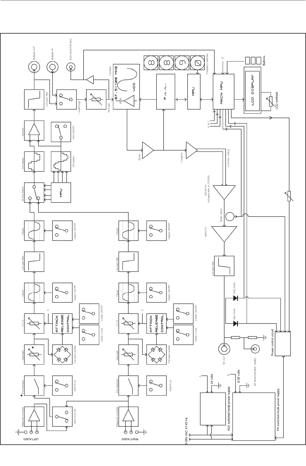
TX25/50 FM Transmitter technical manual page 30
Technical data
3.3 BLOCK DIAGRAM
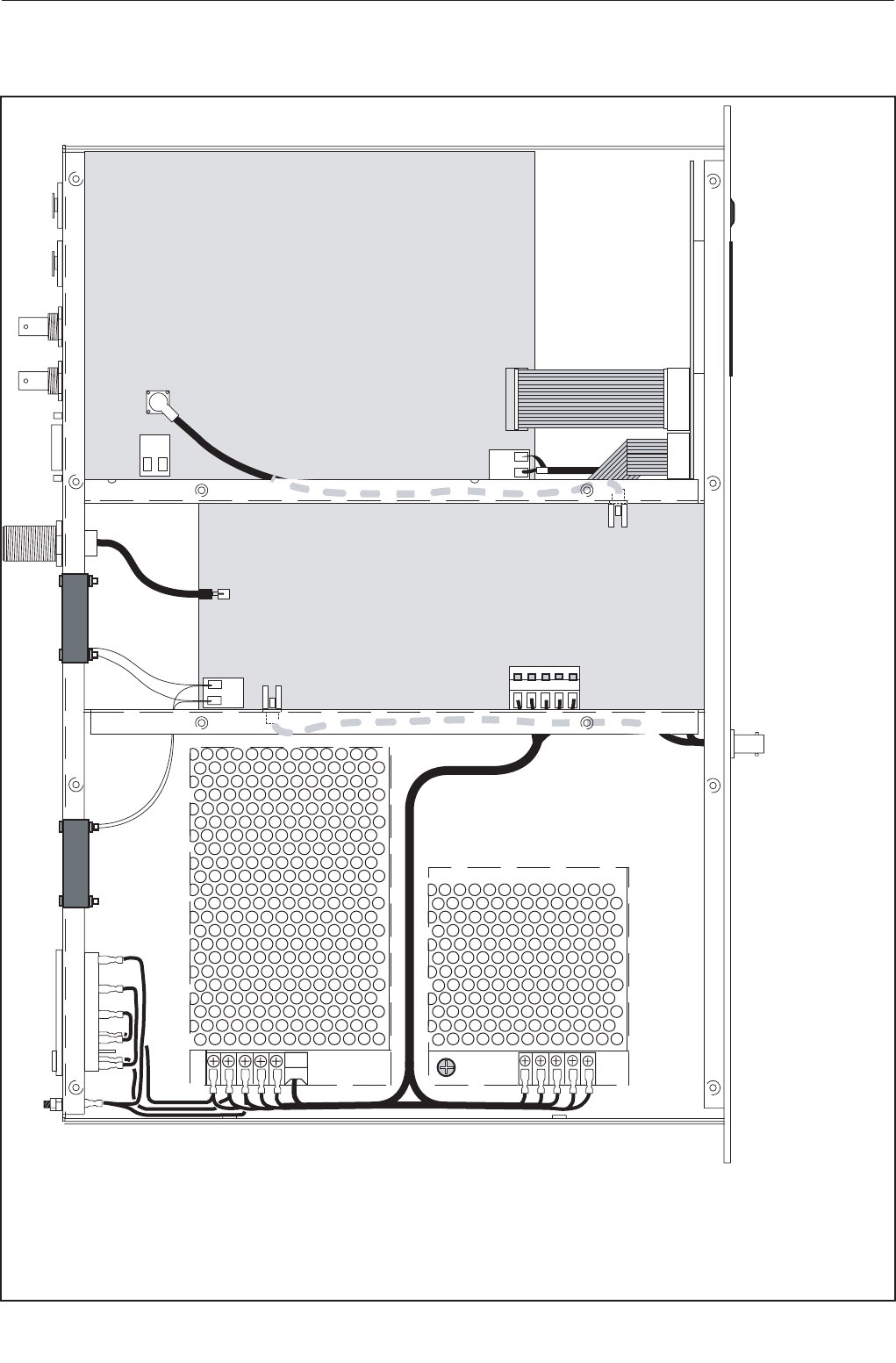
TX25/50 FM Transmitter technical manual page 31
Technical data
Combo board
PA board
LCD board
3.4 WIRING AND INTERNAL OVERVIEW
Wiring details
W1 yellow / green 16 / 0..2
W2 blue 24 / 0.2
W3 brown 24 / 0.2
W4 red 24 /0.2 tri-rated
W5 yellow 24 / 0.2
W6 black 24 / 0.2 tri rated
W7 black 24 / 0.2
W8 red 24 / 0.2
FILTERED IEC MAINS SOCKET
RF & MOD MON BNC’S
RG316 -’N’ BLKHD
16 WY RIBBON
10 WY RIBBON
RG316 MCX-MCX
15 WY ‘D’ TYPE
BNC BNC
XLR
XLR
W5
W4
W6
W2
W1
W6
W1
W1
W7
W8
W4
W3
W2 W3
W4
W6
W5
W7
W8
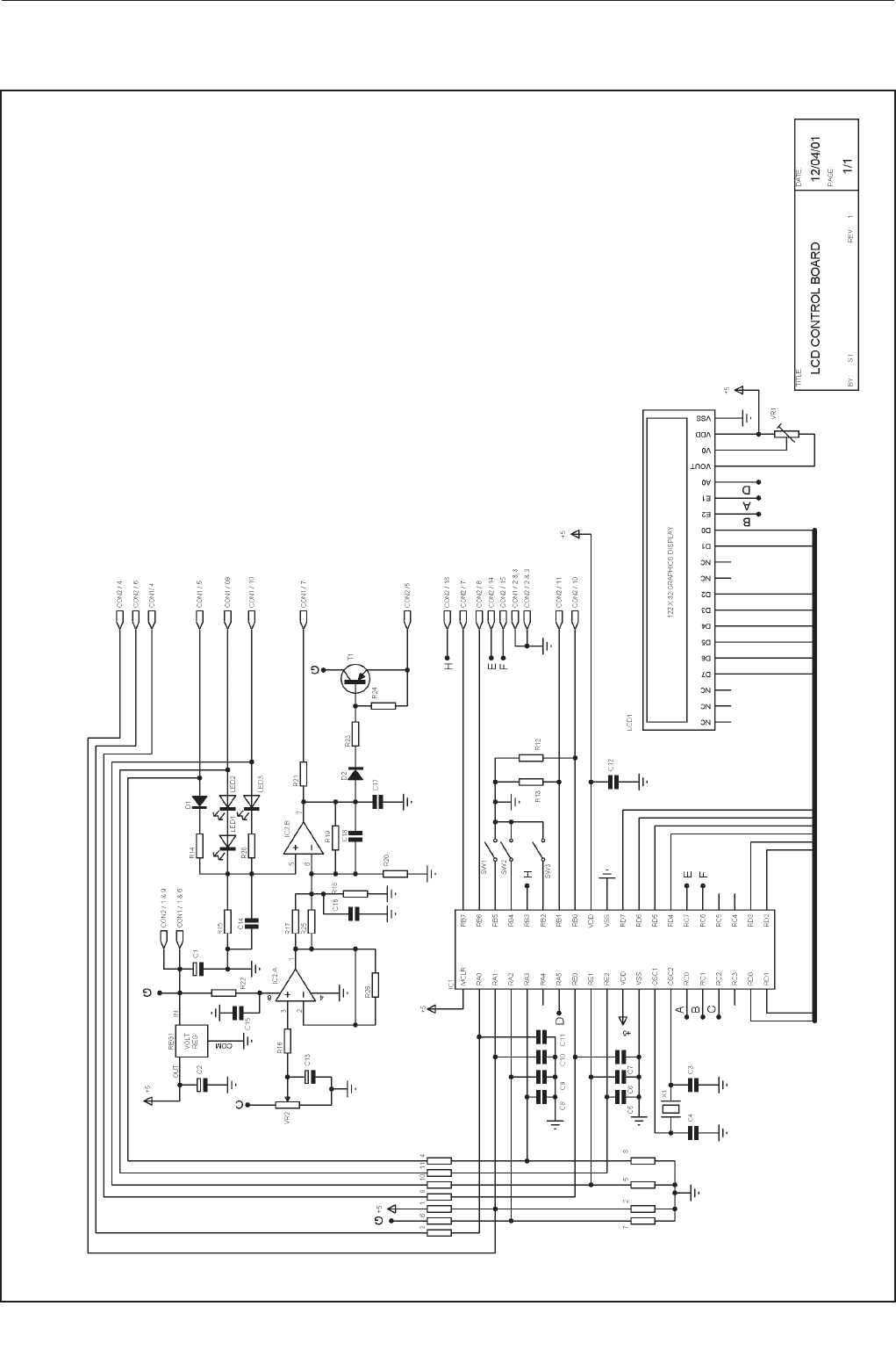
TX25/50 FM Transmitter technical manual page 32
Technical data
3.51 LCD control board
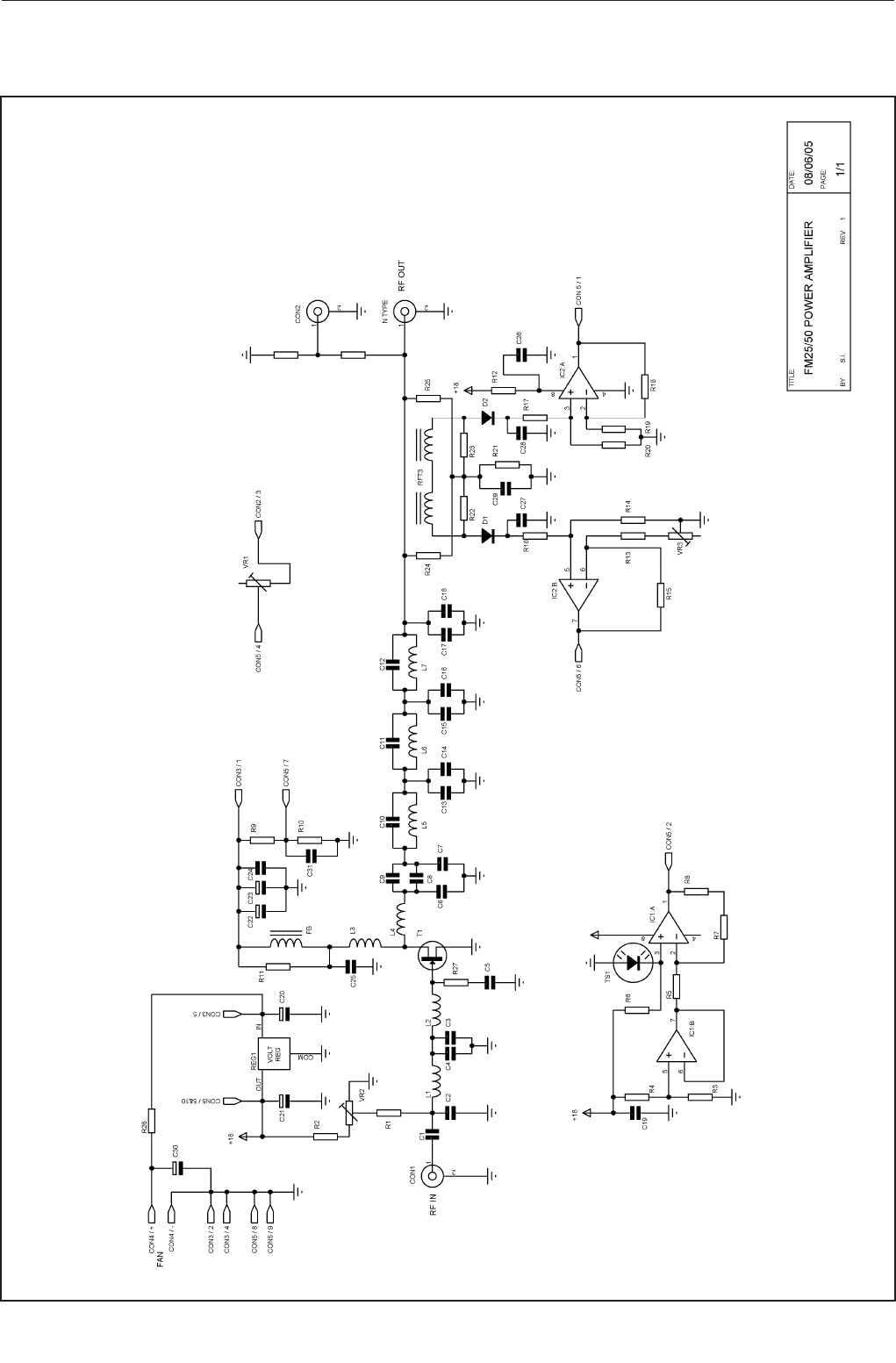
TX25/50 FM Transmitter technical manual page 33
Technical data
3.52 Power amplifier board
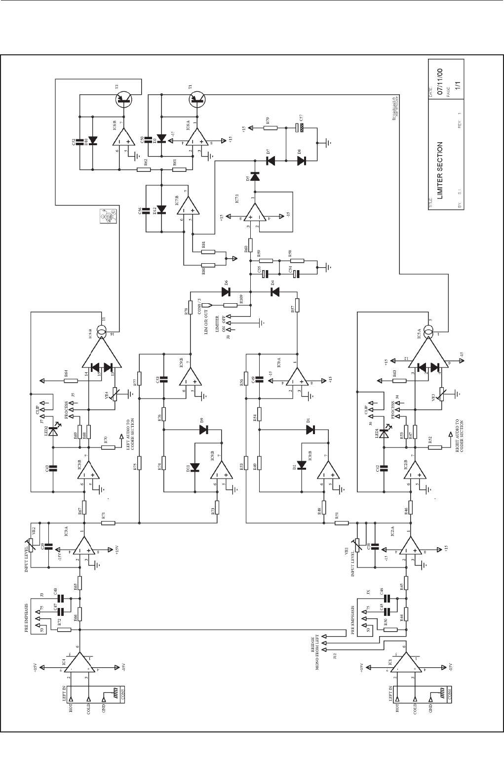
TX25/50 FM Transmitter technical manual page 34
Technical data
3.531Combo board, limiter section
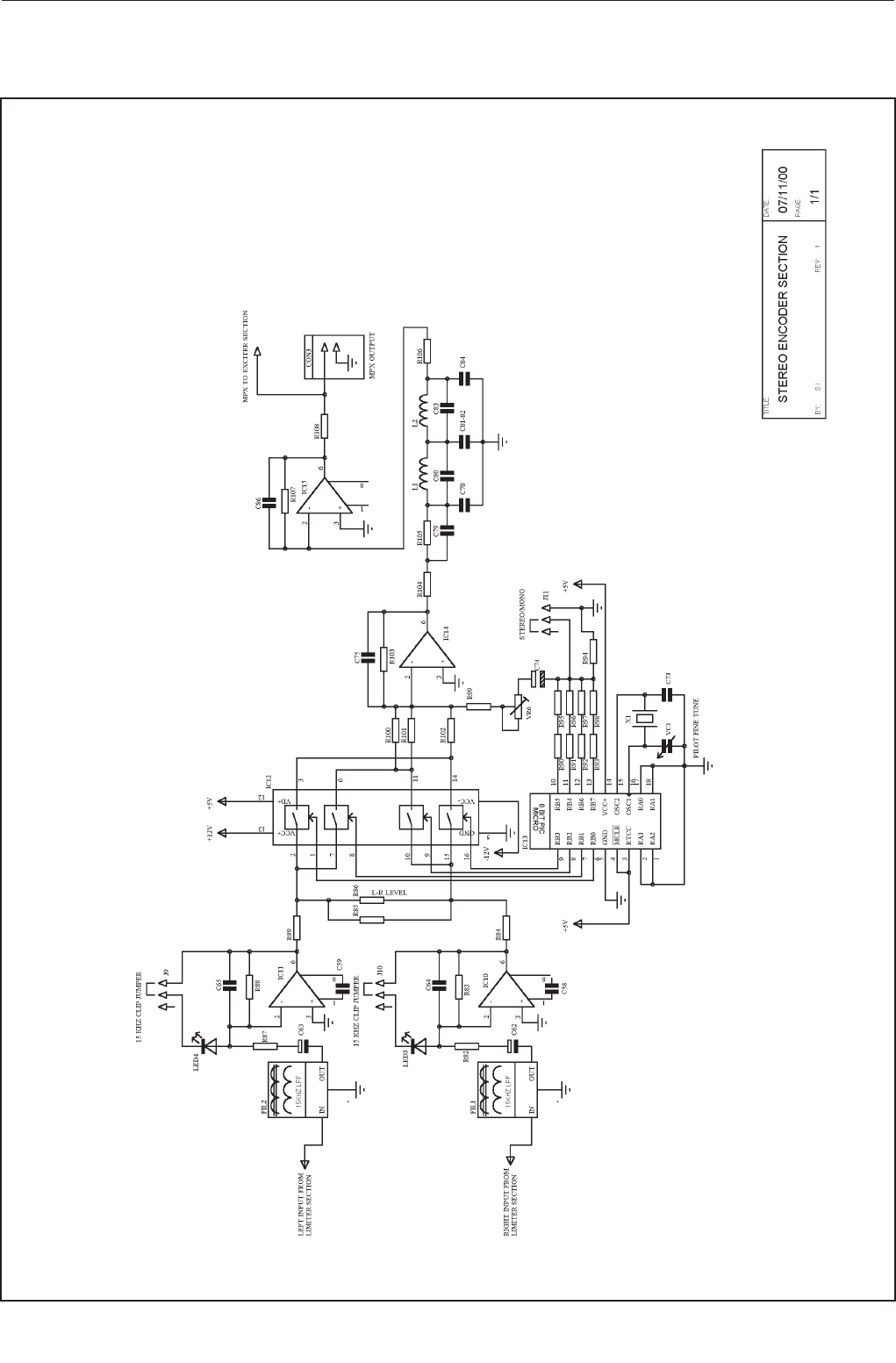
TX25/50 FM Transmitter technical manual page 35
Technical data
3.532 Combo board, stereo encoder section
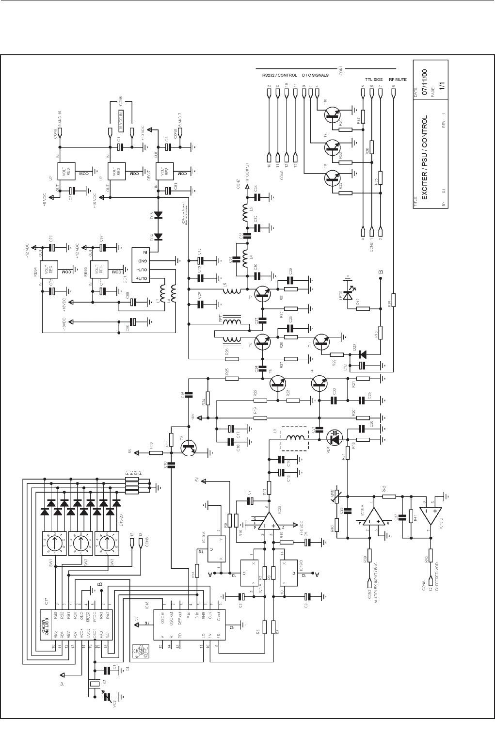
TX25/50 FM Transmitter technical manual page 36
Technical data
3.533 Combo board, PLL exciter section

TX25/50 FM Transmitter technical manual page 37
Technical data
3.6 PARTS LIST
3.61 LCD control board
RESISTORS
R1 33K 1/8 Watt Carbon Film
R2 33K 1/8 Watt Carbon Film
R3 820R 1/8 Watt Carbon Film
R4 390R 1/8 Watt Carbon Film
R5 390R 1/8 Watt Carbon Film
R6 10K 1/8 Watt Carbon Film
R7 820R 1/8 Watt Carbon Film
R8 820R 1/8 Watt Carbon Film
R9 820R 1/8 Watt Carbon Film
R10 820R 1/8 Watt Carbon Film
R11 820R 1/8 Watt Carbon Film
R12 1K8` 1/8 Watt Carbon Film
R13 1K8 1/8 Watt Carbon Film
R14 1K8 1/8 Watt Carbon Film
R15 100R 1/8 Watt Carbon Film
R16 33K 1/8 Watt Carbon Film
R17 620R 1/8 Watt Carbon Film
R18 100R 1/8 Watt Carbon Film
R19 100K 1/8 Watt Carbon Film
R20 100R 1/8 Watt Carbon Film
R21 4K7 1/8 Watt Carbon Film
R22 100R 1/8 Watt Carbon Film
R23 10K 1/8 Watt Carbon Film
R24 10K 1/8 Watt Carbon Film
R25 - not fitted
R26 - not fitted
CAPACITORS
C1 47U Miniature Radial Electrolytic
C2 47U Miniature Radial Electrolytic
C3 33PF Ceramic Plate 2.5 pitch (680)
C4 33PF Ceramic Plate 2.5 pitch (680)
C5-11 560PF Ceramic Plate 2.5 pitch (680)
C12 100N Monolithic Ceramic 2.5 pitch
C13 2U2 Miniature Radial Electrolytic
C14 560PF Ceramic Plate 2.5 pitch (680)
C15 100N Monolithic Ceramic 2.5 pitch
C16 560PF Ceramic Plate 2.5 pitch (680)
C17 560PF Ceramic Plate 2.5 pitch (680)
C18 2U2 Miniature Radial Electrolytic
MISC
VR1 5K 5mm MiniPot
VR2 100K 5mm MiniPot
D1 - LINKED ON PCB
D2 - WIRE LINK
LED1 1N4148 400mW Glass Axial
LED2 GREEN 3MM GREEN LED
LED3 RED 3MM RED LED
X1 8MHZ HC49/U microprocessor crystal
REG1 7805 TO220 1A 5 V regulator
IC1 PIC16F877 40 pin 8 Bit micro Controller
IC2 CA3240 op-amp
T1 TIP32A PNP Transistor
SW1-3 BUTTONS Blue buttons
CON1 10W IDC IDC boxed header
CON2 16W IDC IDC boxed header
LCD1 122x32 NAN YA LMD62S042JM
3.62 Power amplifier board
RESISTORS
R1 3K3 1/4 Watt Metal Oxide
R2 S.O.T 1/4 Watt Metal Oxide
R3 - NOT FITTED
R4 3K3 1/4 Watt Metal Oxide
R5 13K 1/4 Watt Metal Oxide
R6 10K 1/4 Watt Metal Oxide
R7 10K 1/4 Watt Metal Oxide
R8 18K 1/4 Watt Metal Oxide
R9 18K 1/4 Watt Metal Oxide
R10 75R 1/4 Watt Metal Oxide
R11 560R 3 Watt
R12 3R3 2 Watt
R13 6K8 1/4 Watt Metal Oxide
R14 560R 1/4 Watt Metal Oxide
R15 150R 1 Watt
R16 150R 1 Watt
R17 51R 1/4 Watt Metal Oxide
R18 - NOT FITTED
R19 10R 1/4 Watt Metal Oxide
R20 820R 1/4 Watt Metal Oxide
R21 820R 1/4 Watt Metal Oxide
R22 470R 1/4 Watt Metal Oxide
R23 10K 1/4 Watt Metal Oxide
R24 10K 1/4 Watt Metal Oxide
R25 10K 1/4 Watt Metal Oxide
R26 - NOT FITTED
R20 820R 1/4 Watt Metal Oxide
R21 820R 1/4 Watt Metal Oxide
R22 470R 1/4 Watt Metal Oxide
R23 10K 1/4 Watt Metal Oxide
R24 470R 1/4 Watt Metal Oxide
R25 10K 1/4 Watt Metal Oxide
R26 12R 1/4 Watt Metal Oxide
R27 12R 1/4 Watt Metal Oxide
R28 - NOT FITTED
R29 330R 1/4 Watt Metal Oxide
R30 470R 1/4 Watt Metal Oxide
R31 10K 1/4 Watt Metal Oxide
R32 470R 1/4 Watt Metal Oxide
R33 1K 1/4 Watt Metal Oxide
R34 1K 1/4 Watt Metal Oxide
R35 39R SMD 2512
VR1 10K pot
VR2 1K pot
VR3 1K pot
CAPACITORS
C1 470PF 5mm pitch
C2 47PF Disc Ceramic 2.5mm pitch
C3 120PF Disc Ceramic 2.5mm pitch
C4 100PF Disc Ceramic 2.5mm pitch
C5 10N Disc Ceramic 2.5mm pitch
C6 0.1U Min Polyester
C7 330PF Disc Ceramic 2.5mm pitch
C8 22U Electrolytic 63V Radial
C9 22U Electrolytic 63V Radial
C10 10N Disc Ceramic 2.5mm pitch
C11 100U Electrolytic 63V Radial

TX25/50 FM Transmitter technical manual page 38
Technical data
C12 100U Electrolytic 63V Radial
C13 10N Disc Ceramic 2.5mm pitch
C14 10N Disc Ceramic 2.5mm pitch
C15 10N Disc Ceramic 2.5mm pitch
C16 2N2 SMD
C17 2N2 SMD
C18 47PF Disc Ceramic 2.5mm pitch
C19 47PF Disc Ceramic 2.5mm pitch
C20 47PF Disc Ceramic 2.5mm pitch
C21 39PF Minature low K 2.5mm pitch
C22 - NOT FITTED
C23 47PF Disc Ceramic 2.5mm pitch
C24 39PF Minature low K 2.5mm pitch
C25 8P2 Ceramic 2.5 pitch
C26 18P Minature low K 2.5mm pitch
C27 22P Disc Ceramic 2.5mm pitch
C28 12P Minature low K 2.5mm pitch
C29 22P Disc Ceramic 2.5mm pitch
C30 3.3P Disc Ceramic 2.5mm pitch
C31 1N High Voltage
C32 100U Electrolytic 63V Radial
C33 100U Electrolytic 63V Radial
C34 10N Disc Ceramic 2.5mm pitch
C35 10N Disc Ceramic 2.5mm pitch
C36 10N Disc Ceramic 2.5mm pitch
C37 10N Disc Ceramic 2.5mm pitch
C38 10N Disc Ceramic 2.5mm pitch
C39 10N Disc Ceramic 2.5mm pitch
C40 10N Disc Ceramic 2.5mm pitch
INDUCTORS
L1 4 TURN COIL 0.9mm silvered copper wire
L2 2 TURN COIL 0.9mm silvered copper wire
L3 COIL S18 Orange Toko
L4 2 TURN COIL 18 Gauge silvered copper wire
L5 2 TURN COIL 18 Gauge silvered copper wire
L6 COIL S18 Red Toko
L7 COIL S18 Red Toko
L8 FB Axial Ferrite bead
MISC
REG1 7818 18 V 1A Regulator
IC1 CA3240 op-amp
IC2 CA3240 op-amp
T1 SRFE1130P RF Power Transistor
D1 BAT42 Rectifier Diode
D2 BAT42 Rectifier Diode
TS1 LM335Z Temperature sensor
CON1 PCB MCX MCX connector
CON2 PCB MCX MCX connector
CON3 5Term 5 Way Screwless Terminal
CON4 4Term 4 Way Screwless Terminal
CON5 10Way IDC Box Header 90 degree
RFT1 RFT VSWR Coupler Toroid
3.63 Combo board
CAPACITORS
C1 2.2 uF 16V Miniature Radial Electrolytic
C2 2.2 uF 16V Miniature Radial Electrolytic
C3 100n Y5V Monolithic Ceramic 2.5 pitch
C4 39pF Ceramic Plate 2.5 pitch (680)
C5 2.2 uF 16V Miniature Radial Electrolytic
C6 470uF 16V Radial Electrolytic
C7 470uF 16V Radial Electrolytic
C8 2.2 uF 16V Miniature Radial Electrolytic
C9 2.2 uF 16V Miniature Radial Electrolytic
C10 82pF Ceramic Plate 2.5 pitch (680)
C11 100n Y5V Monolithic Ceramic 2.5 pitch
C12 100uF 16V Monolithic Ceramic 2.5 pitch
C13 2.2 uF 16V Miniature Radial Electrolytic
C14 100n Y5V Monolithic Ceramic 2.5 pitch
C15 82pF Ceramic Plate 2.5 pitch (680)
C16 100n Y5V Monolithic Ceramic 2.5 pitch
C17 100uF 16V Radial Electrolytic
C18 100uF 16V Radial Electrolytic
C19 1n Gen. Pur. Ceramic Disc 2.5 pitch
C20 220pF Ceramic Plate 2.5 pitch (680)
C21 4p7 Ceramic Plate 2.5 pitch (680)
C22 27pF Ceramic Plate 2.5 pitch (680)
C23 56pF Ceramic Plate 2.5 pitch (680)
C24 82pF Ceramic Plate 2.5 pitch (680)
C25 1n Gen. Pur. Ceramic Disc 2.5 pitch
C26 100n Y5V Monolithic Ceramic 2.5 pitch
C27 82pF Ceramic Plate 2.5 pitch (680)
C28 100n Y5V Monolithic Ceramic 2.5 pitch
C29 100n Y5V Monolithic Ceramic 2.5 pitch
C30 27pF Ceramic Plate 2.5 pitch (680)
C31 12pF Ceramic Plate 2.5 pitch (680)
C32 56pF Ceramic Plate 2.5 pitch (680)
C33 1n Gen. Pur. Ceramic Disc 2.5 pitch
C34 33pF Ceramic Plate 2.5 pitch (680)
C35 Not Used
C36 100n Y5V Monolithic Ceramic 2.5 pitch
C37 Not Used
C38 47pF Ceramic Plate 2.5 pitch (680)
C39 47pF Ceramic Plate 2.5 pitch (680)
C40 100n Y5V Monolithic Ceramic 2.5 pitch
C41 100n Y5V Monolithic Ceramic 2.5 pitch
C42 47pF Ceramic Plate 2.5 pitch (680)
C43 47pF Ceramic Plate 2.5 pitch (680)
C44 100n Y5V Monolithic Ceramic 2.5 pitch
C45 4n7 Polycarbonate 5mm Pitch
C46 6n8 Polycarbonate 5mm Pitch
C47 6n8 Polycarbonate 5mm Pitch
C48 4n7 Polycarbonate 5mm Pitch
C49 27pF Ceramic Plate 2.5 pitch (680)
C50 47pF Ceramic Plate 2.5 pitch (680)
C51 100n Y5V Monolithic Ceramic 2.5 pitch
C52 47pF Ceramic Plate 2.5 pitch (680)
C53 27pF Ceramic Plate 2.5 pitch (680)
C54 47uF 16V Miniature Radial Electrolytic
C55 10uF 16v Miniature Radial Electrolytic
C56 47pF Ceramic Plate 2.5 pitch (680)
C57 47uF 16V Miniature Radial Electrolytic
C58 27pF Ceramic Plate 2.5 pitch (680)
C59 27pF Ceramic Plate 2.5 pitch (680)
C60 100n Y5V Monolithic Ceramic 2.5 pitch
C61 100n Y5V Monolithic Ceramic 2.5 pitch
C62 47uF 16V Miniature Radial Electrolytic
C63 47uF 16V Miniature Radial Electrolytic
C64 330pF Ceramic Plate 2.5 pitch (680)
C65 330pF Ceramic Plate 2.5 pitch (680)
C66 100n Y5V Monolithic Ceramic 2.5 pitch
C67 47uF 16 Miniature Radial Electrolytic
C68 100n Y5V Monolithic Ceramic 2.5 pitch
C69 100n Y5V Monolithic Ceramic 2.5 pitch
C70 47uF 16V Miniature Radial Electrolytic
C71 100n Y5V Monolithic Ceramic 2.5 pitch

TX25/50 FM Transmitter technical manual page 39
Technical data
C72 2.2uF 16V Miniature Radial Electrolytic
C73 39pF Ceramic Plate 2.5 pitch (680)
C74 2.2uF 16V Miniature Radial Electrolytic
C75 12pF Ceramic Plate 2.5 pitch (680)
C76 100n Y5V Monolithic Ceramic 2.5 pitch
C77 2.2uF 16V Miniature Radial Electrolytic
C78 330pF Ceramic Plate 2.5 pitch (680)
C79 100n Y5V Monolithic Ceramic 2.5 pitch
C80 100pF Ceramic Plate 2.5 pitch (680)
C81 330pF Ceramic Plate 2.5 pitch (680)
C82 330pF Ceramic Plate 2.5 pitch (680)
C83 - Not Used
C84 330pF Ceramic Plate 2.5 pitch (680)
C85 100n Y5V Monolithic Ceramic 2.5 pitch
C86 12pF Ceramic Plate 2.5 pitch (680)
C87 100n Y5V Monolithic Ceramic 2.5 pitch
C88 47uF 16V Miniature Radial Electrolytic
C89 470uf 16V Radial Electrolytic
C90 470uf 16V Radial Electrolytic
C91 2.2uF 16V Miniature Radial Electrolytic
C92 100n Y5V Monolithic Ceramic 2.5 pitch
C93 10uF 35V Miniature Radial Electrolytic
C94 39pF
VC1 5-65pF Variable capacitor
MISC
IC1 TL071 Low noise Op-Amp
IC2-3 TL072 Low noise Dual Op-Amp
IC4 TL071 Low noise Op-Amp
IC5 LM13600 Transconductance Amplifier
IC6-7 TL072 Low noise Dual Op-Amp
IC8-9 TL072 Low noise Op-Amp
IC10-11 TL071 Low noise Op-Amp
IC12 DG201-HS Analog Switch
IC13 16C620A-04P 8 Bit Microcontroller
IC14 TL071 Low noise Op-Amp
IC15 TL071 Low noise Op-Amp
IC16 TL072 Low noise Op-Amp
IC17 PIC16CE623-20P8 Bit Microcontroller
IC18 MC145170-P PLL synth. Chip
IC19 4066 Analog Switch
IC20 LF351 Bi-Fet op-amp
T1-2 BC327 PNP General Purpose
T3-6 MPHS10 High Speed Switching
T7 2N4427 High Speed Switching
T8-10 BC337 NPN General Purpose
T11 MPSH10 High Speed Switching
J1-12 3 PIN 3 Pin Jumper Header
FIL1-2 5085 15KHz Block Filters
X1 4.864MHz HC49 Microprocessor crystal
X2 8.000MHz HC49 Microprocessor crystal
DC1 NMH1215S Newport 2W dual output DC
convertor
RFT1 4 to 1 Tx 4 Turns Blue / Yellow Ferrite/Ring)
SW1-4 DEC ROTA. Decimal Rotary PCB switches
FB FB Axial Ferrite Bead
HEATS. TO5 SINK Push On T05 Heatsink
8 PIN 8PIN 8 Pin IC Holders X 14
14 PIN 14 PIN 14 Pin IC Holders X 1
16 PIN 16 PIN 16 Pin IC Holders X 3
18 PIN 18 PIN 18 Pin IC Holders X 2
INDUCTORS
L1 3.9mH 10RB Radial Inductor
L2 4.7mH 10RB Radial Inductor
L3 MC120 075 Screened Variable Inductor
L4 S18 2.5T Moulded Variable Inductor
L5 S18 3.5T Moulded Variable Inductor
L6 .15uH Axial Inductor
L7-8 220uH Axial Inductor
RESISTORS
R1 10K 1/8 Watt Carbon Film
R2 10K 1/8 Watt Carbon Film
R3 10K 1/8 Watt Carbon Film
R4 10K 1/8 Watt Carbon Film
R5 10K 1/8 Watt Carbon Film
R6 10K 1/8 Watt Carbon Film
R7 330K 1/8 Watt Carbon Film
R8 330K 1/8 Watt Carbon Film
R9 10K 1/8 Watt Carbon Film
R10 470R 1/8 Watt Carbon Film
R11 33K 1/8 Watt Carbon Film
R12 1K2 1/8 Watt Carbon Film
R13 1K2 1/8 Watt Carbon Film
R14 330K 1/8 Watt Carbon Film
R15 330R 1/8 Watt Carbon Film
R16 330R 1/8 Watt Carbon Film
R17 1K2 1/8 Watt Carbon Film
R18 100R 1/4 Watt Metal Oxide
R19 12K 1/8 Watt Carbon Film
R20 4K7 1/8 Watt Carbon Film
R21 220R 1/8 Watt Carbon Film
R22 1K2 1/8 Watt Carbon Film
R23 1K2 1/8 Watt Carbon Film
R24 68R 1/8 Watt Carbon Film
R25 180R 1/8 Watt Carbon Film
R26 4K7 1/8 Watt Carbon Film
R27 470R 1/8 Watt Carbon Film
R28 10R 1/8 Watt Carbon Film
R29 4K7 1/8 Watt Carbon Film
R30 220R 1/8 Watt Carbon Film
R31 2R2 1/8 Watt Carbon Film
R32 1K2 1/8 Watt Carbon Film
R33 1K2 1/8 Watt Carbon Film
R34 1K2 1/8 Watt Carbon Film
R35 1K2 1/8 Watt Carbon Film
R36 1K2 1/8 Watt Carbon Film
R37 1K2 1/8 Watt Carbon Film
R38 10R 1/8 Watt Carbon Film
R39 2K2 1/4 Watt Metal Oxide
R40 1K 1/4 Watt Metal Oxide
R41 560R 1/4 Watt Metal Oxide
R42 820R 1/4 Watt Metal Oxide
R43 75R 1/4 Watt Metal Oxide
R44 12K 1/4 Watt Metal Oxide
R45 1K 1/4 Watt Metal Oxide
R46 36K 1/4 Watt Metal Oxide
R47 7K5 1/4 Watt Metal Oxide
R48 24K 1/4 Watt Metal Oxide
R49 24K 1/4 Watt Metal Oxide
R50 470R 1/4 Watt Metal Oxide
R51 1K 1/4 Watt Metal Oxide
R52 3K3 1/4 Watt Metal Oxide
R53 100K 1/4 Watt Metal Oxide
R54 12K 1/4 Watt Metal Oxide
R55 24K 1/4 Watt Metal Oxide
R56 24K 1/4 Watt Metal Oxide
R57 200R 1/4 Watt Metal Oxide
R58 24K 1/4 Watt Metal Oxide
R59 3K3 1/4 Watt Metal Oxide
R60 12K 1/4 Watt Metal Oxide
R61 7K5 1/4 Watt Metal Oxide
R62 7K5 1/4 Watt Metal Oxide

TX25/50 FM Transmitter technical manual page 40
Technical data
R63 16K 1/4 Watt Metal Oxide
R64 16K 1/4 Watt Metal Oxide
R65 1K 1/4 Watt Metal Oxide
R66 12K 1/4 Watt Metal Oxide
R67 36K 1/4 Watt Metal Oxide
R68 7K5 1/4 Watt Metal Oxide
R69 100K 1/4 Watt Metal Oxide
R70 3K3 1/4 Watt Metal Oxide
R71 1K 1/4 Watt Metal Oxide
R72 470R 1/4 Watt Metal Oxide
R73 24K 1/4 Watt Metal Oxide
R74 24K 1/4 Watt Metal Oxide
R75 24K 1/4 Watt Metal Oxide
R76 12K 1/4 Watt Metal Oxide
R77 24K 1/4 Watt Metal Oxide
R78 200R 1/4 Watt Metal Oxide
R79 12K 1/4 Watt Metal Oxide
R80 470K 1/4 Watt Metal Oxide
R81 470K 1/4 Watt Metal Oxide
R82 3K3 1/4 Watt Metal Oxide
R83 6k8 1/4 Watt Metal Oxide
R84 10R 1/4 Watt Metal Oxide
R85 470R 1/4 Watt Metal Oxide
R86 12K 1/4 Watt Metal Oxide
R87 3K3 1/4 Watt Metal Oxide
R88 6K8 1/4 Watt Metal Oxide
R89 10R 1/4 Watt Metal Oxide
R90 5K6 1/4 Watt Metal Oxide
R91 12K 1/4 Watt Metal Oxide
R92 47K 1/4 Watt Metal Oxide
R93 120K 1/4 Watt Metal Oxide
R94 1K 1/4 Watt Metal Oxide
R95 4K3 1/4 Watt Metal Oxide
R96 12K 1/4 Watt Metal Oxide
R97 3K3 1/4 Watt Metal Oxide
R98 1K 1/4 Watt Metal Oxide
R99 6K8 1/4 Watt Metal Oxide
R100 1M 1/4 Watt Metal Oxide
R101 10K 1/4 Watt Metal Oxide
R102 24K 1/4 Watt Metal Oxide
R103 5K1 1/4 Watt Metal Oxide
R104 5K3 1/4 Watt Metal Oxide
R105 100R 1/4 Watt Metal Oxide
R106 3K6 1/4 Watt Metal Oxide
R107 11K 1/4 Watt Metal Oxide
R108 75R 1/4 Watt Metal Oxide
R109 10K 1/4 Watt Metal Oxide
R110 10K 1/4 Watt Metal Oxide
R111 SOR SORT ON TEST
R112 10K 1/4 Watt Metal Oxide
R113 10K 1/4 Watt Metal Oxide
R114 10K 1/4 Watt Metal Oxide
R115 10K 1/4 Watt Metal Oxide
R116 10K 1/4 Watt Metal Oxide
R117 10K 1/4 Watt Metal Oxide
R118 10K 1/4 Watt Metal Oxide
R119 10K 1/4 Watt Metal Oxide
R120 10R 1/4 Watt Metal Oxide
R121 75R 1/4 Watt Metal Oxide
VR1-2 10K Horizontal Multiturn
VR3-4 1K Vertical Multiturn
VR5 10K Horizontal Multiturn
VR6 10K Horizontal 5MM Pitch
DIODES
D1-12 1N4148 Glass axial general purpose Diode
D13 1N4001 Axial 1 amp silicon rectifier diode
D14 4R7 4R7 OHM RESISTOR
D15-30 1N4148 Glass axial general purpose Diode
VD1 BB809 VHF varicap Diode
LED1-4 GREEN BI Bi directional 5mm Green LED
LED5 RED 5mm Standard RED LED
REG1 7815 1 A TO220 15 V Linear Reg
REG2 7805 1 A TO220 5 V Linear Reg
REG3 78L10 100 mA TO92 10 V Linear Reg
REG4 79L12 100 mA TO92 -12 V Linear Reg
REG5 78L12 100 mA TO92 +12 V Linear Reg
CON 1 15 WAY D Right Angled Female 15 D PCB
CON 2-3R/A BNC Right Angled PCB BNC
CON 4-5R/A XLR Right Angled XLR
CON6 2 TERM 2 Way Screwless Terminal
CON7 R/A RCA Pcb mount RCA Socket
CON8 IDC HEAD 10 or 16 way IDC straight header
CON9 2 TERM 2 Way Screwless Terminal