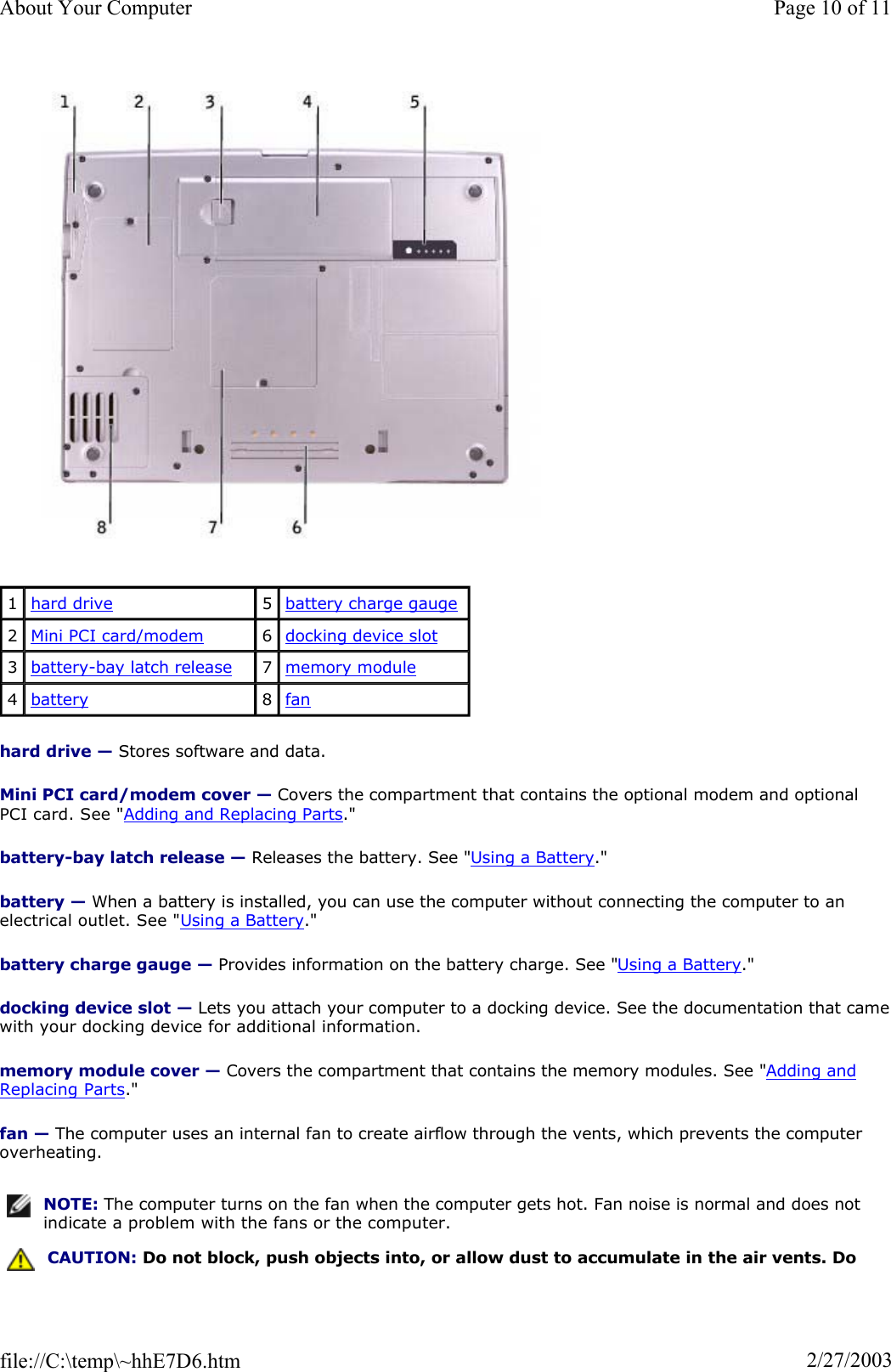
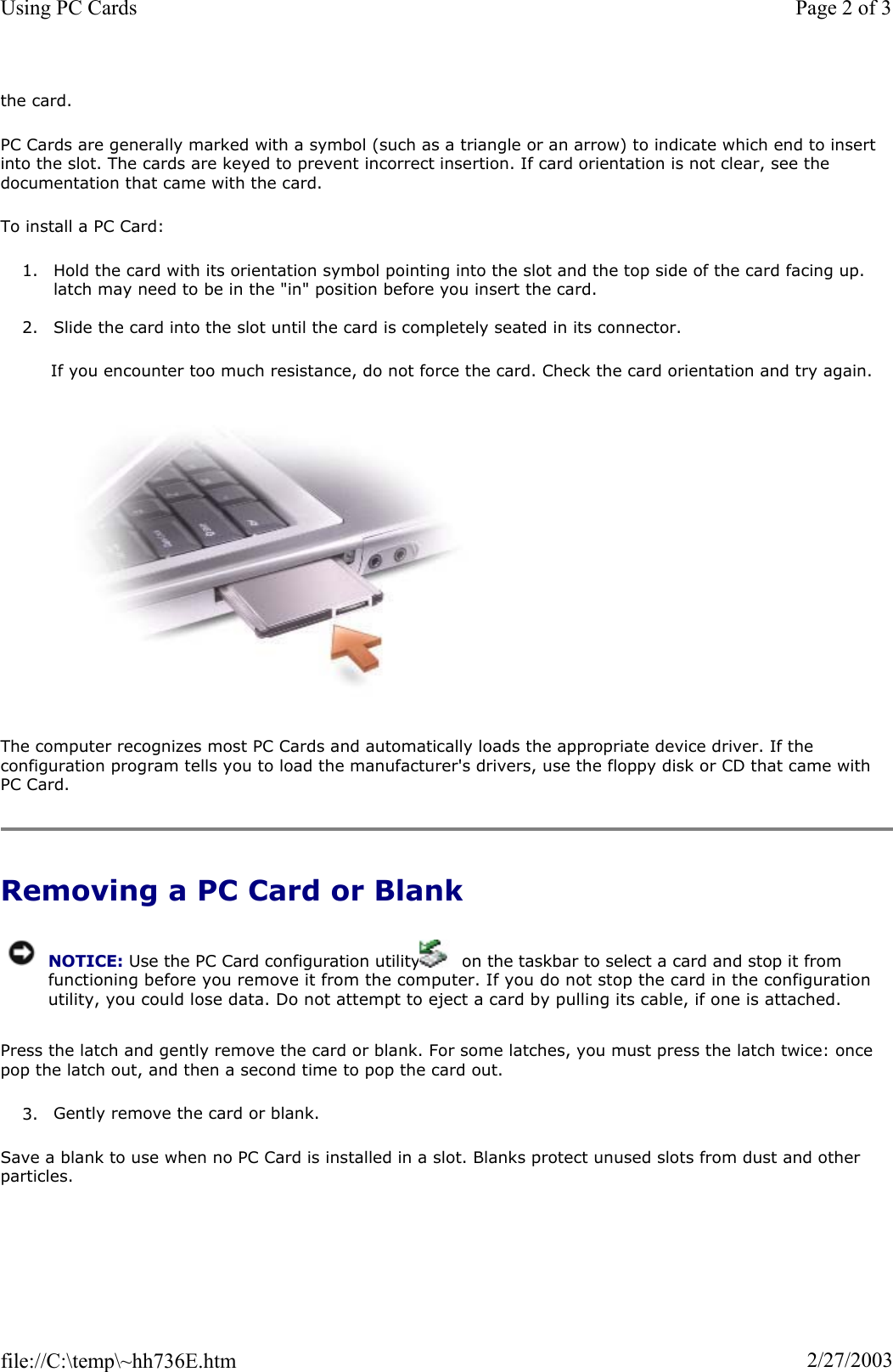
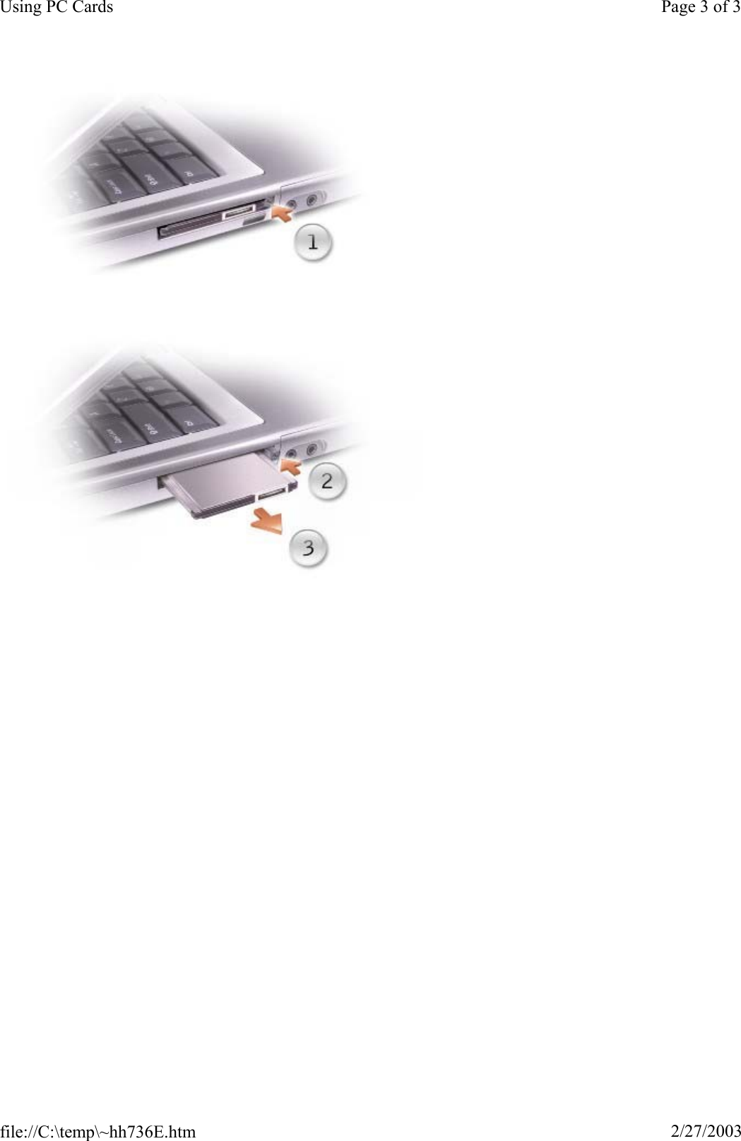
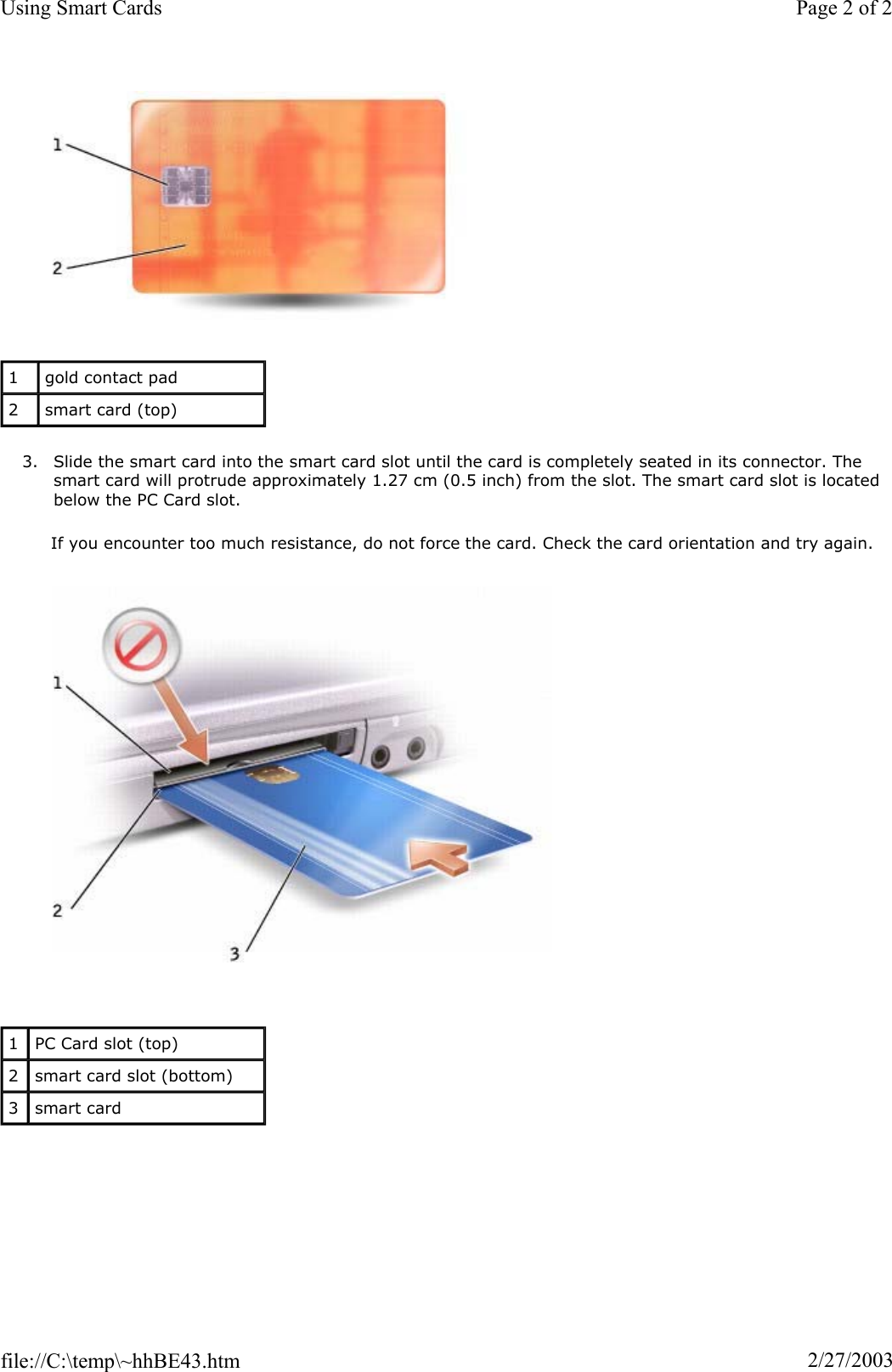
Broadcom BRCM1005-D 802.11g MINI PCI Card build in Laptops User Manual PP02X User Guide
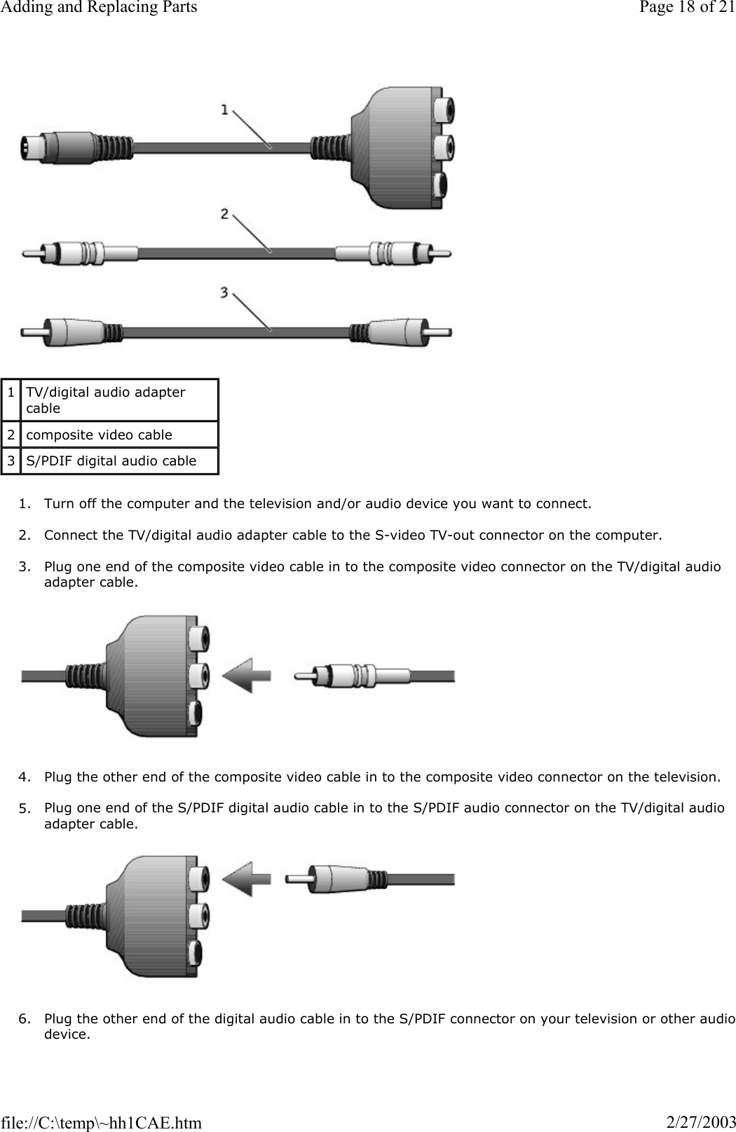
Broadcom Corporation 802.11g MINI PCI Card build in Laptops PP02X User Guide
Broadcom >
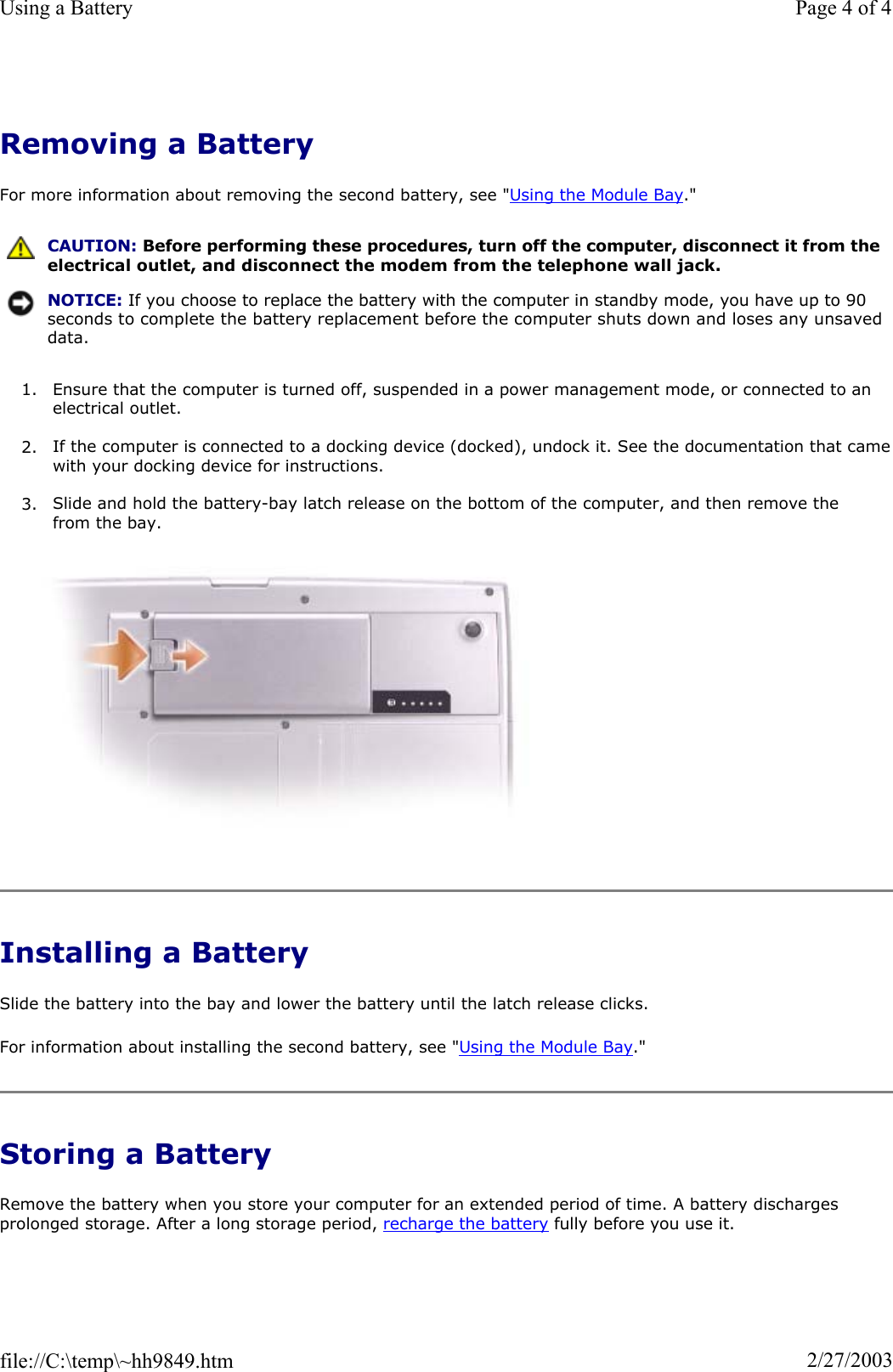
Contents
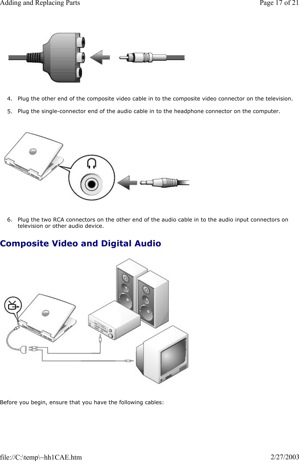
- 1. PP02X User Guide Main
- 2. PP05L User Guide Main
- 3. PP07L User Guide Main
- 4. WLAN User Guide
- 5. Users Manual
PP02X User Guide Main

![To continue, enter your password (maximum eight characters). Press to return the computer to its previous state. If you do not enter a password within 2 minutes, the computer returns to its previous state. If you enter the wrong password, the following message appears: Invalid password [Press Enter to retry]If the correct password is not entered in three attempts, the computer tries to boot from another bootable device if the Boot First Device option in the system setup program is set to allow it. If the Boot First option is not set to allow booting from another device, the computer returns to the state it was in when you turned it on. If the hard drive password, the external hard drive password, and the primary password are the same, you prompted only for the primary password. If the hard drive password is different from the primary password, are prompted for both. Two different passwords provide greater security. Assigning an Asset Tag The Asset Tag utility allows you to enter an asset tag that you or your company assigns to the computer. Afteryou enter an asset tag, the tag appears in the system setup screens. You can also use the Asset Tag utility to enter an owner tag that appears in the system log-on screen and withthe primary password prompt. Use your Drivers and Utilities CD to create a bootable floppy disk, and then use the bootable floppy disk to assign an asset tag: 1. Save and close any open files and exit any open programs. 2. Connect the Dell™ D/Bay with a floppy drive to the Dell D/Bay connector on the right side of the computer, or connect a USB floppy drive to one of the two USB connectors on the back of the 3. Insert the Drivers and Utilities CD. 4. When the Welcome Dell System Owner window appears, click Next. 5. Select MS-DOS from the Operating System drop-down menu. 6. Click Dell Portables Asset Tag, click Extract, and then click Setup.7. Insert a blank floppy disk and press . Follow the instructions on the screen to create a bootable floppy disk. 8. Boot the computer using the bootable floppy disk: a. Restart the computer. NOTE: The administrator password provides access to the computer, but it does not provide access to a hard drive that is protected by a hard drive password.Page 3 of 5Passwords2/27/2003file://C:\temp\~hh5B03.htm](https://usermanual.wiki/Broadcom/BRCM1005-D.PP02X-User-Guide-Main/User-Guide-307781-Page-59.png)


![TaiwanInternational Access Code: 002Country Code: 886Technical Support (portable and desktop computers) toll-free: 00801 86 1011Technical Support (servers) toll-free: 0080 60 1256Transaction Sales toll-free: 0080 651 228or 0800 33 556Corporate Sales toll-free: 0080 651 227or 0800 33 555ThailandInternational Access Code: 001Country Code: 66Technical Support toll-free: 0880 060 07Customer Service (Penang, Malaysia) 604 633 4949Sales toll-free: 0880 060 09Trinidad/Tobago General Support 1-800-805-8035Turks and Caicos IslandsGeneral Support toll-free: 1-866-540-3355U.K. (Bracknell)International Access Code: 00Country Code: 44City Code: 1344Website: support.euro.dell.comCustomer Care website: dell.co.uk/lca/customerservicesE-mail: dell_direct_support@dell.com Technical Support (Corporate/Preferred Accounts/PAD [1000+ employees]) 0870 908 0500Technical Support (direct/PAD and general) 0870 908 0800Global Accounts Customer Care 01344 373 185or 01344 373 186Home and Small Business Customer Care 0870 906 0010Corporate Customer Care 0870 908 0500Preferred Accounts (500–5000 employees) Customer Care 01344 373 196Central Government Customer Care 01344 373 193Local Government & Education Customer Care 01344 373 199Health Customer Care 01344 373 194Home and Small Business Sales 0870 907 4000Corporate/Public Sector Sales 01344 860 456Uruguay General Support toll-free: 000-413-598-U.S.A. (Austin, Texas)International Access Code: 011Country Code: 1Automated Order-Status Service toll-free: 1-800-433-9014AutoTech (portable and desktop computers) toll-free: 1-800-247-9362Consumer (Home and Home Office) Technical Support toll-free: 1-800-624-9896Customer Service toll-free: 1-800-624-9897Page 15 of 16Getting Help2/27/2003file://C:\temp\~hh9AFD.htm](https://usermanual.wiki/Broadcom/BRCM1005-D.PP02X-User-Guide-Main/User-Guide-307781-Page-135.png)
![DellNet™ Service and Support toll-free: 1-877-Dellnet(1-877-335-5638)Employee Purchase Program (EPP) Customers toll-free: 1-800-695-8133Financial Services website: www.dellfinancialservices.comFinancial Services (lease/loans) toll-free: 1-877-577-3355Financial Services (Dell Preferred Accounts [DPA]) toll-free: 1-800-283-2210BusinessCustomer Service and Technical Support toll-free: 1-800-822-8965Employee Purchase Program (EPP) Customers toll-free: 1-800-695-8133Projectors Technical Support toll-free: 1-877-459-7298Public (government, education, and healthcare) Customer Service and Technical Support toll-free: 1-800-456-3355Employee Purchase Program (EPP) Customers toll-free: 1-800-234-1490Dell Sales toll-free: 1-800-289-3355or toll-free: 1-800-879-3355 Dell Outlet Store (Dell refurbished computers) toll-free: 1-888-798-7561Software and Peripherals Sales toll-free: 1-800-671-3355Spare Parts Sales toll-free: 1-800-357-3355Extended Service and Warranty Sales toll-free: 1-800-247-4618Fax toll-free: 1-800-727-8320Dell Services for the Deaf, Hard-of-Hearing, or Impaired toll-free: 1-877-DELLTTY(1-877-335-5889)U.S. Virgin Islands General Support 1-877-673-3355Venezuela General Support 8001-3605Page 16 of 16Getting Help2/27/2003file://C:\temp\~hh9AFD.htm](https://usermanual.wiki/Broadcom/BRCM1005-D.PP02X-User-Guide-Main/User-Guide-307781-Page-136.png)
![AppendixMacrovision Product NoticeErgonomic Computing HabitsRegulatory NoticesWarranty and Return PolicyMacrovision Product Notice This product incorporates copyright protection technology that is protected by method claims of certain U.S. patents and other intellectual property rights owned by Macrovision Corporation and other rights owners. Use this copyright protection technology must be authorized by Macrovision Corporation and is intended for home and other limited viewing uses only unless otherwise authorized by Macrovision Corporation. Reverse engineering or disassembly is prohibited. Ergonomic Computing Habits For comfort and efficiency, observe the following ergonomic guidelines when setting up and using your workstation: zPosition your computer directly in front of you as you work. zAdjust the tilt of the computer's display, its contrast and/or brightness settings, and the lighting around you (such as overhead lights, desk lamps, and the curtains or blinds on nearby windows) to minimize reflections and glare on the display. zWhen using an external monitor with your computer, set the monitor at a comfortable viewing distance (usually 450 to 610 millimeters [18 to 24 inches] from your eyes). Make sure the monitor screen is at level or slightly lower when you are sitting in front of the monitor. zUse a chair that provides good lower-back support. zKeep your forearms horizontal with your wrists in a neutral, comfortable position while using the keyboard, touch pad, track stick, or external mouse. zAlways use the palm rest with the keyboard, touch pad, or track stick. Leave space to rest your hands when using an external mouse. zLet your upper arms hang naturally at your sides. zEnsure that your feet are resting flat on the floor. zWhen sitting, make sure the weight of your legs is on your feet and not on the front of your chair seat. Adjust your chair's height or use a footrest, if necessary, to maintain proper posture. CAUTION: Improper or prolonged keyboard use may result in CAUTION: Viewing the display or external monitor screen for extended periods of time may result in eye strain.Page 1 of 14Appendix2/27/2003file://C:\temp\~hh6397.htm](https://usermanual.wiki/Broadcom/BRCM1005-D.PP02X-User-Guide-Main/User-Guide-307781-Page-143.png)


![GlossaryA B C D E F G H I K L M N O P R S T U V W X ZTerms in this Glossary are provided for informational purposes only and may or may not describe features included with your particular computer. AAC — alternating current — The form of electricity that powers your computer when you plug the AC adapter power cable in to an electrical outlet. ACPI — advanced configuration and power interface — A power management specification that enables Microsoft® Windows® operating systems to put a computer in standby or hibernate mode to conserve the amount of electrical power allocated to each device attached to the computer. AGP — accelerated graphics port — A dedicated graphics port that allows system memory to be used for related tasks. AGP delivers a smooth, true-color video image because of the faster interface between the circuitry and the computer memory. antivirus software — A program designed to identify, quarantine, and/or delete viruses from your computer.APR — advanced port replicator — A docking device that allows you to conveniently use a monitor, keyboard, mouse, and other devices with your portable computer. ASF — alert standards format — A standard to define a mechanism for reporting hardware and software alertsto a management console. ASF is designed to be platform- and operating system-independent. Bbackup — A copy of a program or data file on a floppy disk, CD, or hard drive. As a precaution, back up the data files from your hard drive regularly. battery — An internal power source used to operate portable computers when not connected to an AC and an electrical outlet. battery life span — The length of time (years) during which a portable computer battery is able to be and recharged. battery operating time — The length of time (minutes or hours) that a portable computer battery holds a charge while powering the computer. BIOS — basic input/output system — A program (or utility) that serves as an interface between the computer hardware and the operating system. Unless you understand what effect the settings have on the computer, not change the settings for this program. Also referred to as the system setup program.bit — The smallest unit of data interpreted by your computer. Bluetooth™ — A wireless technology standard for short-range (9 m [29 feet]) networking devices that allows Page 1 of 14Glossary2/27/2003file://C:\temp\~hhE039.htm](https://usermanual.wiki/Broadcom/BRCM1005-D.PP02X-User-Guide-Main/User-Guide-307781-Page-157.png)