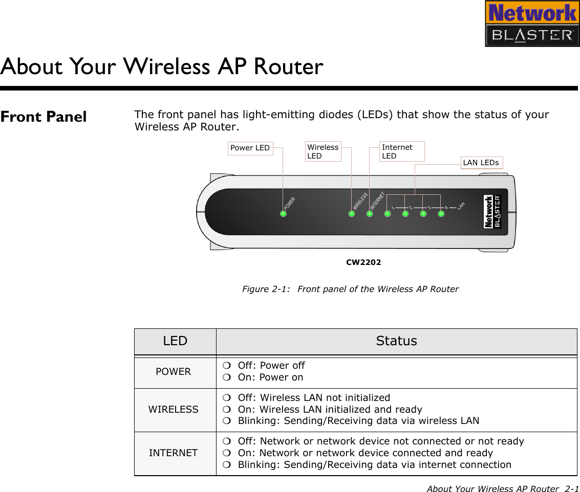
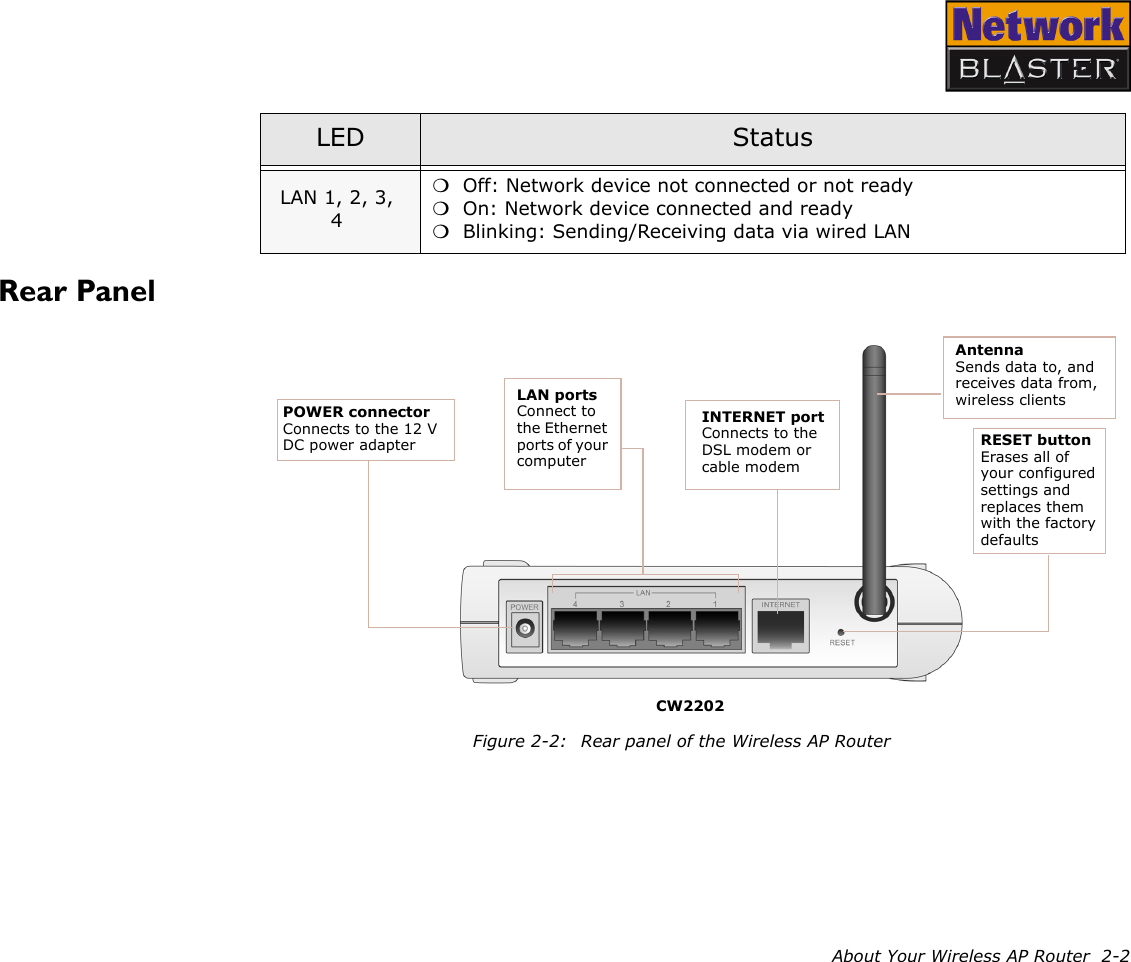
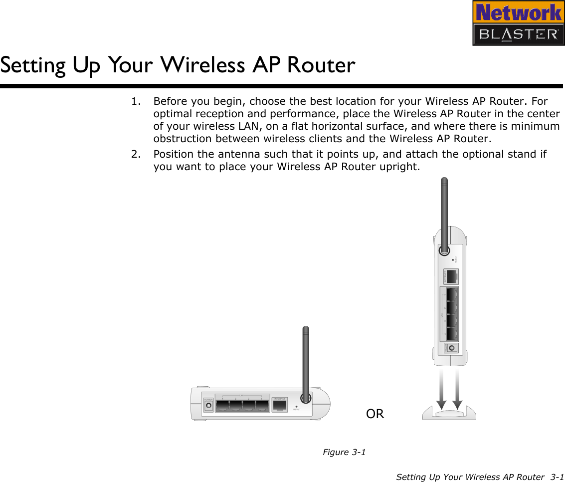
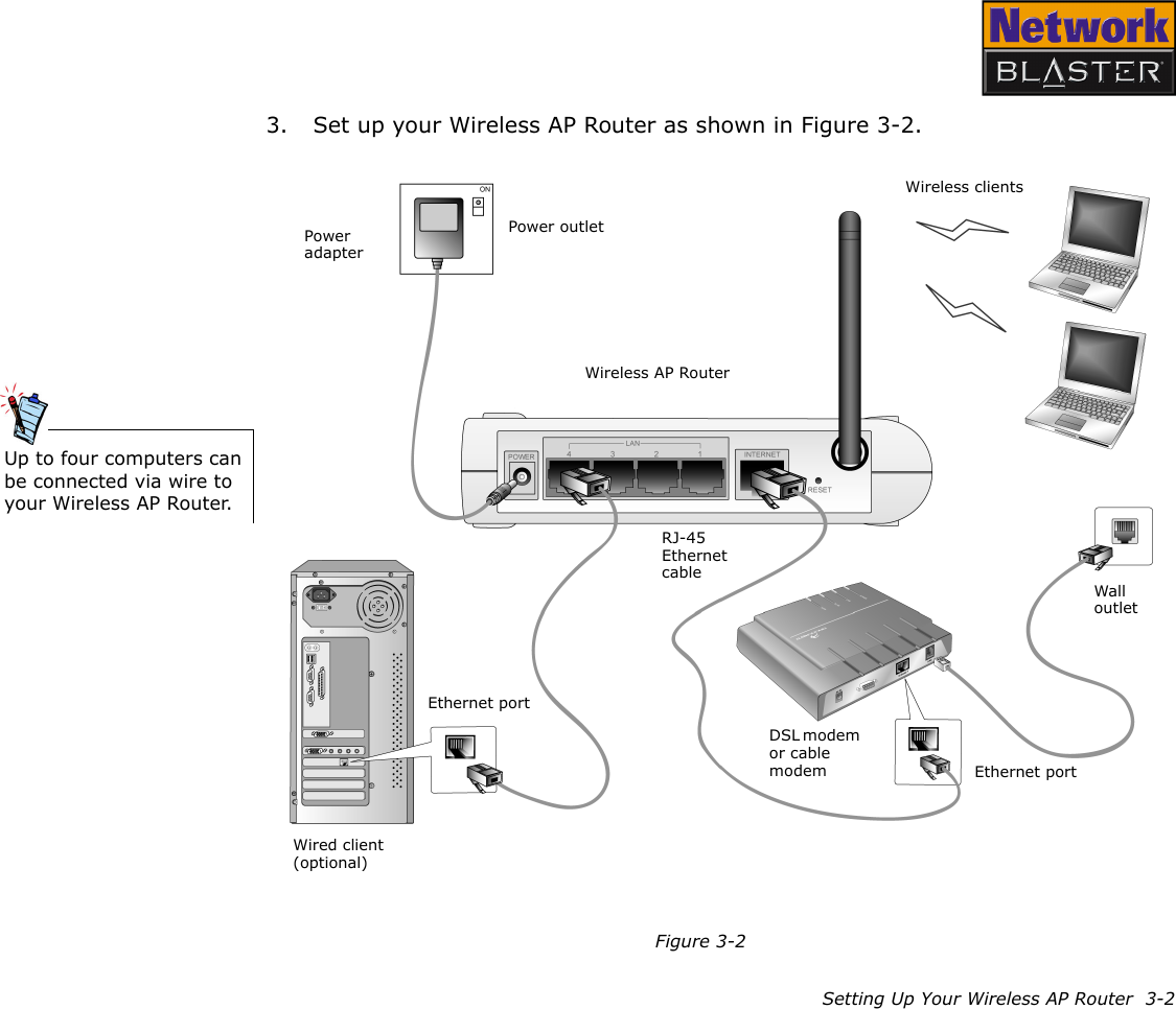
Broadxent CW2202-4 Wireless Access Point Router User Manual Introduction
Broadxent Pte Ltd. Wireless Access Point Router Introduction
UserManual.wiki
>
Broadxent
>
CW2202 4 User Manual
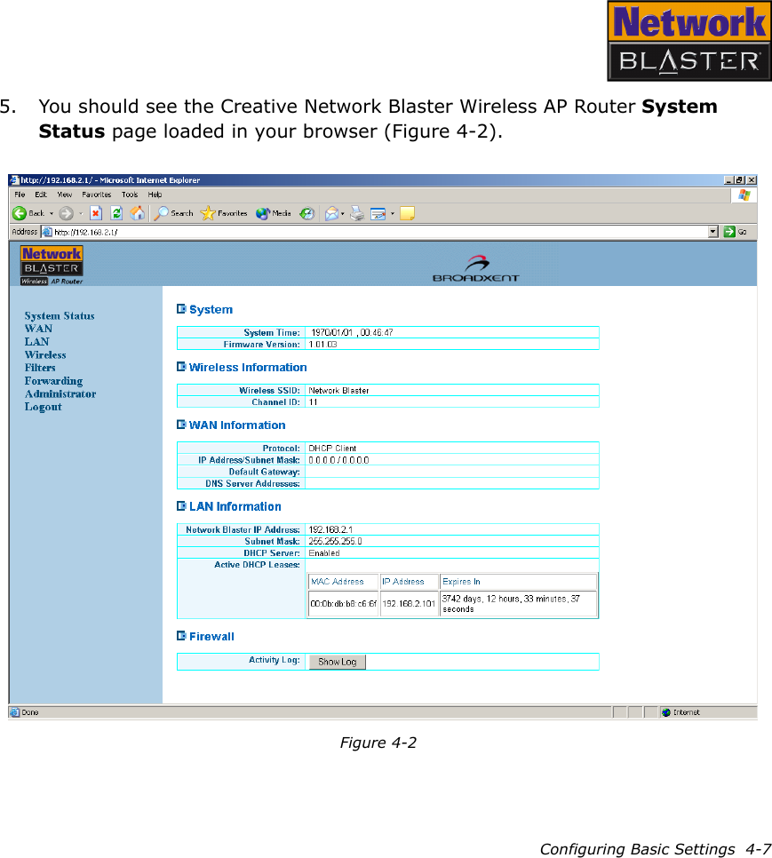
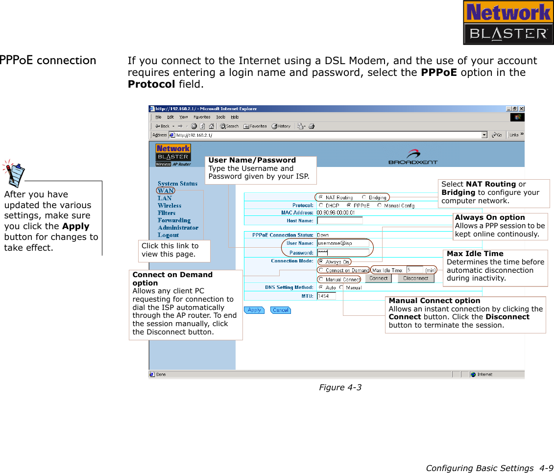
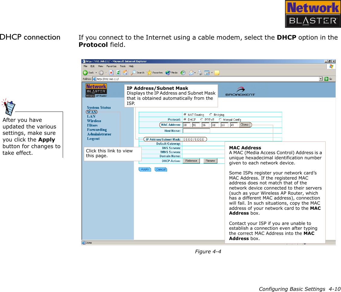
Users Manual
Navigation menu
Upload a User Manual
Namespaces
Wiki Guide
HTML
PDF
Info
Views
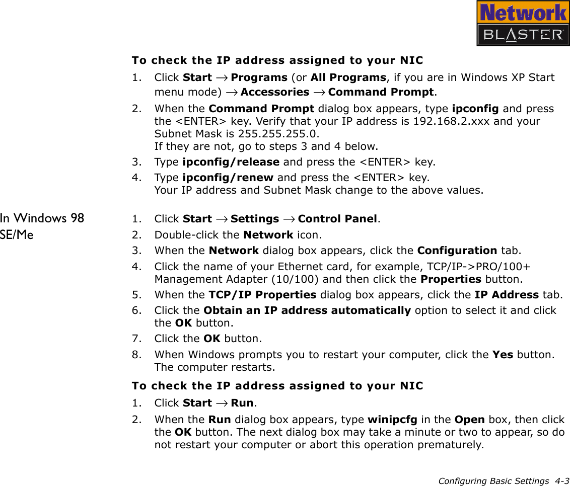
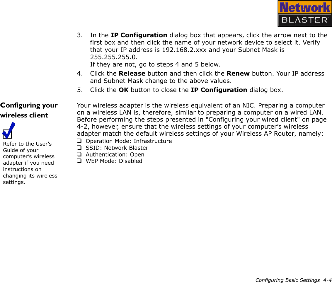
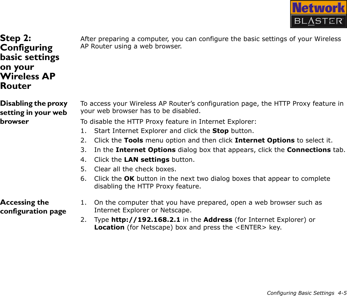
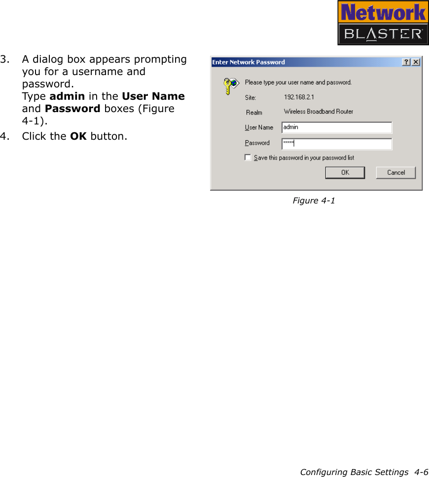
User Manual
Discussion / Help
Navigation