Broadxent CW2202-4 Wireless Access Point Router User Manual Introduction
Broadxent Pte Ltd. Wireless Access Point Router Introduction
Users Manual

User’s Guide
Network Blaster Wireless Access Point Router CW2202
Information in this document is subject to change without notice and does not represent a commitment on the part of Creative
Technology Ltd. No part of this manual may be reproduced or transmitted in any form or by any means, electronic or mechanical,
including photocopying and recording, for any purpose without the written permission of Creative Technology Ltd. The software
described in this document is furnished under a license agreement and may be used or copied only in accordance with the terms of
the license agreement. It is against the law to copy the software on any other medium except as specifically allowed in the license
agreement. The licensee may make one copy of the software for backup purposes only.
The Software License Agreement is found in a separate folder on the Application CD.
Copyright © 2004 by Creative Technology Ltd. All rights reserved.
Version 1.1
July 2004
The Creative logo, Blaster, Network Blaster and Turbo-G are registered trademarks or trademarks of Creative Technology Ltd. in the
United States and/or other countries. Microsoft, MS-DOS, Windows and the Windows logo are registered trademarks of Microsoft
Corporation. Intel and Pentium are registered trademarks of Intel Corporation. All other products are trademarks or registered
trademarks of their respective owners and are hereby recognized as such. All specifications are subject to change without prior
notice. Actual contents may differ slightly from those pictured.

Contents

i i
Contents
Introduction
Package Contents ........................................................................................................................... 1-1
System Requirements .................................................................................................................... 1-1
Model Number, Serial Number and MAC Address ............................................................ 1-2
More Help ......................................................................................................................................... 1-2
Product Registration ...................................................................................................................... 1-2
Customer Support Services and Warranty ........................................................................... 1-2
Document Conventions ............................................................................................................... 1-3
About Your Wireless AP Router
Front Panel ................................................................................................................................................. 2-1
Rear Panel ................................................................................................................................................... 2-2
Setting Up Your Wireless AP Router
Configuring Basic Settings
Step 1: Preparing a client ...................................................................................................................... 4-2
Configuring your wired client ..................................................................................................... 4-2
Configuring your wireless client ................................................................................................ 4-4
Step 2: Configuring basic settings on your Wireless AP Router ............................................... 4-5
Disabling the proxy setting in your web browser ................................................................ 4-5
Accessing the configuration page ............................................................................................... 4-5
Configuring Internet connection settings ................................................................................ 4-8
Configuring Wireless LAN settings ........................................................................................ 4-12
Configuring Wireless Security settings .................................................................................. 4-13

ii ii
Configuring Advanced Settings
Configuring LAN settings ............................................................................................................. 5-1
Configuring Wireless MAC Address Access Control ........................................................ 5-2
Configuring Forwarding settings ................................................................................................ 5-3
Configuring Wireless Advanced settings ................................................................................ 5-4
Changing router web page access password ......................................................................... 5-5
Upgrading Firmware ...................................................................................................................... 5-6
Restoring or saving a profile ........................................................................................................ 5-7
Resetting the Wireless AP Router ............................................................................................ 5-8
Appendixes
A About Wireless LANs
Features and Benefits of Wireless LANs ......................................................................................... A-1
About Ad-Hoc Mode ............................................................................................................................. A-2
About Infrastructure Mode .................................................................................................................. A-3
Setting Up Wireless LANs ................................................................................................................... A-4
B Frequently Asked Questions
Turbo-G ...................................................................................................................................................... B-1
C Technical Specifications
Standards .......................................................................................................................................... C-1
Interface ............................................................................................................................................ C-1
Antenna ............................................................................................................................................ C-1
Frequency Band .............................................................................................................................. C-1
Data Rate ......................................................................................................................................... C-1

iii iii
Channels ........................................................................................................................................... C-1
Security ............................................................................................................................................. C-1
Dimensions ...................................................................................................................................... C-1
D Safety Precautions
General Safety .......................................................................................................................................... D-1
Exposure to Radio Frequency Caution ............................................................................................ D-1
Power Adapter Safety Notice ............................................................................................................. D-1
Power Source ................................................................................................................................. D-1
Cleaning ............................................................................................................................................ D-2
Damage Requiring Servicing ....................................................................................................... D-2
Servicing ............................................................................................................................................ D-2
E Glossary

Introduction

Introduction 1-1
Introduction
Thank you for choosing the Creative Network Blaster™ Wireless Access Point (AP)
Router.
Your Creative wireless device comes equipped with Turbo-G™ technology, which
improves your device's performance by 35%, without affecting that of other
wireless local area network (WLAN) devices in the neighbourhood. Powerful router
functions and a user-friendly web-based configuration make it easy to set up and
share a single broadband Internet connection with multiple clients. Other features
include backward compatibility with IEEE 802.11b devices, an auto-sensing
function that lets you achieve the fastest possible connection speeds, and robust
WEP or WPA-PSK encryption.
Note: If you are new to networking, you may initially find the prospect of setting up a
networking solution daunting. But with a little patience and the aid of this User’s Guide, you
will not only be able to establish a working network, but a secure one as well.
Package
Contents
The following items are included in your package:
❑Creative Network Blaster Wireless AP Router CW2202
❑Power adapter (12 V DC, 1 A)
❑RJ-45 Ethernet cable
❑Stand for Wireless AP Router
❑Quick Start leaflet
❑Application CD
System
Requirements
❑Installed network interface card with RJ-45 Ethernet port, or a wireless network client
(IEEE 802.11b or 802.11g compliant)
❑Internet Explorer version 6.0
Introduction 1-2
Model Number,
Serial Number
and MAC Address
Record the model number, serial number and the MAC addresses on your Wireless
AP Router.
You will need to provide the model and serial numbers when contacting Technical
Support. You may also need to provide the MAC addresses to a network
administrator if you plan to use your device on a large network, such as in a school
or office.
More Help Depending on the type of broadband internet service that you subscribe to, you
may need additional information from your Internet Service Provider (ISP) to
complete the setup of your Wireless AP Router. Contact your ISP's customer or
technical support staff for details.
Product
Registration
Enjoy a host of benefits by registering your product during installation, or at
www.creative.com/register. Benefits include:
❑Service and product support from Creative
❑Exclusive updates on promotions and events
Customer
Support Services
and Warranty
You can find Customer Support Services, Warranty and other information in the
Installation CD.
(replace d:\ with the drive letter of your CD-ROM/DVD-ROM drive, <region> with
the region that you are in, and <language> with the language that your
document is in).
Customer Support
Services
d:\support\<language>\support.pdf
Warranty d:\warranty\<region>\<language>\warranty.pdf
Please keep your Proof of Purchase for the duration of the
warranty period.
Regulatory d:\fcc\<language>\doc.pdf

Introduction 1-3
Document
Conventions
This User’s Guide uses the following icons to highlight useful or urgent information.
Tip. This tells you about short cuts or hints relating to a feature.
Note. This highlights additional or important information about a
feature.
Caution! This highlights proper usage of your product. Follow these
directions to prevent the loss of data, or damage to your product or
system.
Warning! This warns you of possible hazards that may result in
bodily harm or life-threatening situations.

About Your Wireless AP Router
About Your Wireless AP Router 2-1
About Your Wireless AP Router
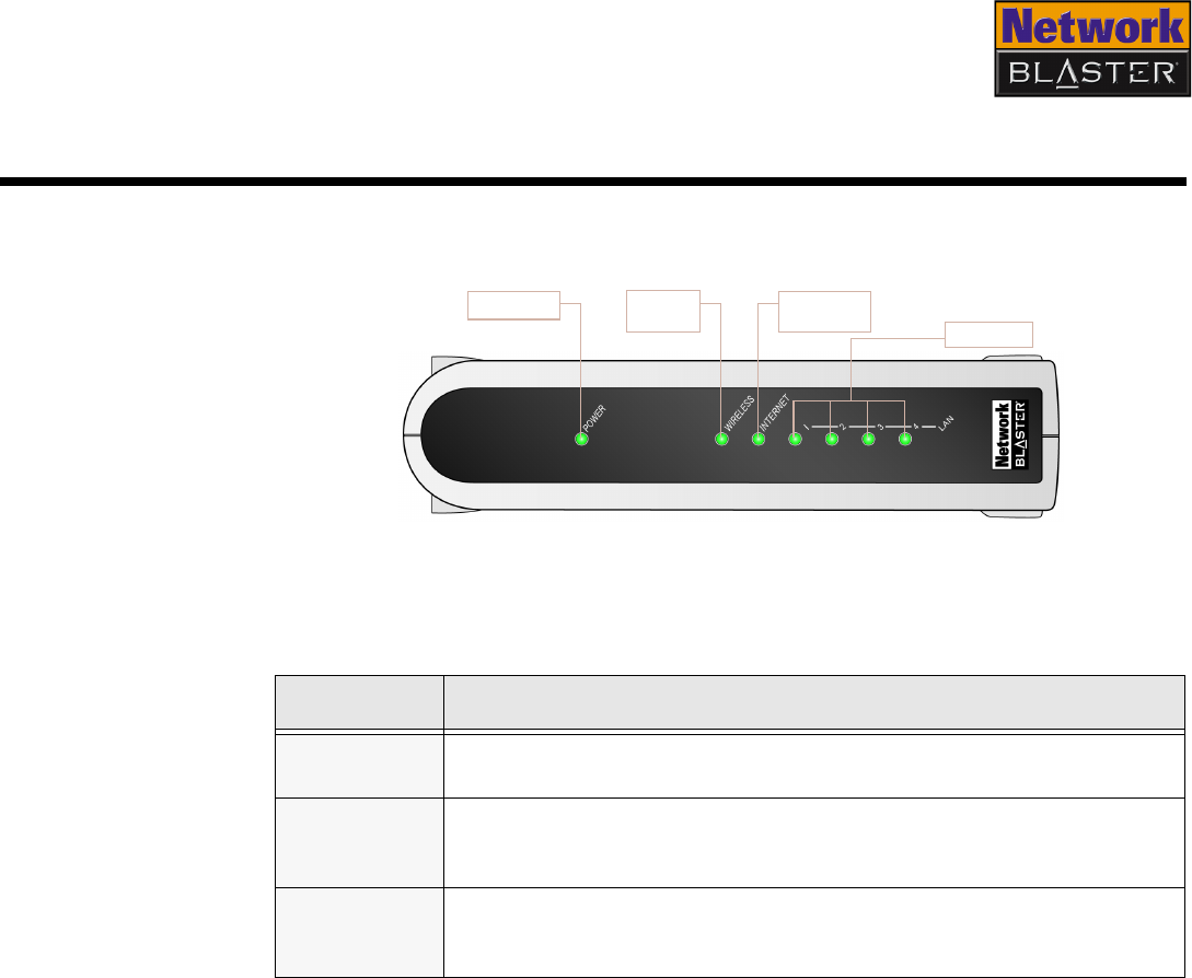
Front Panel The front panel has light-emitting diodes (LEDs) that show the status of your
Wireless AP Router.
LED Status
POWER ❍Off: Power off
❍On: Power on
WIRELESS
❍Off: Wireless LAN not initialized
❍On: Wireless LAN initialized and ready
❍Blinking: Sending/Receiving data via wireless LAN
INTERNET
❍Off: Network or network device not connected or not ready
❍On: Network or network device connected and ready
❍Blinking: Sending/Receiving data via internet connection
Figure 2-1: Front panel of the Wireless AP Router
CW2202
LAN LEDs
Power LED Wireless
LED
Internet
LED
About Your Wireless AP Router 2-2
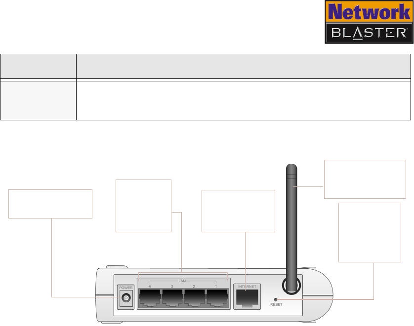
Rear Panel
LAN 1, 2, 3,
4
❍Off: Network device not connected or not ready
❍On: Network device connected and ready
❍Blinking: Sending/Receiving data via wired LAN
LED Status
Figure 2-2: Rear panel of the Wireless AP Router
RESET button
Erases all of
your configured
settings and
replaces them
with the factory
defaults
INTERNET port
Connects to the
DSL modem or
cable modem
CW2202
LAN ports
Connect to
the Ethernet
ports of your
computer
Antenna
Sends data to, and
receives data from,
wireless clients
POWER connector
Connects to the 12 V
DC power adapter

Setting Up Your Wireless AP
Router
Setting Up Your Wireless AP Router 3-1
Setting Up Your Wireless AP Router
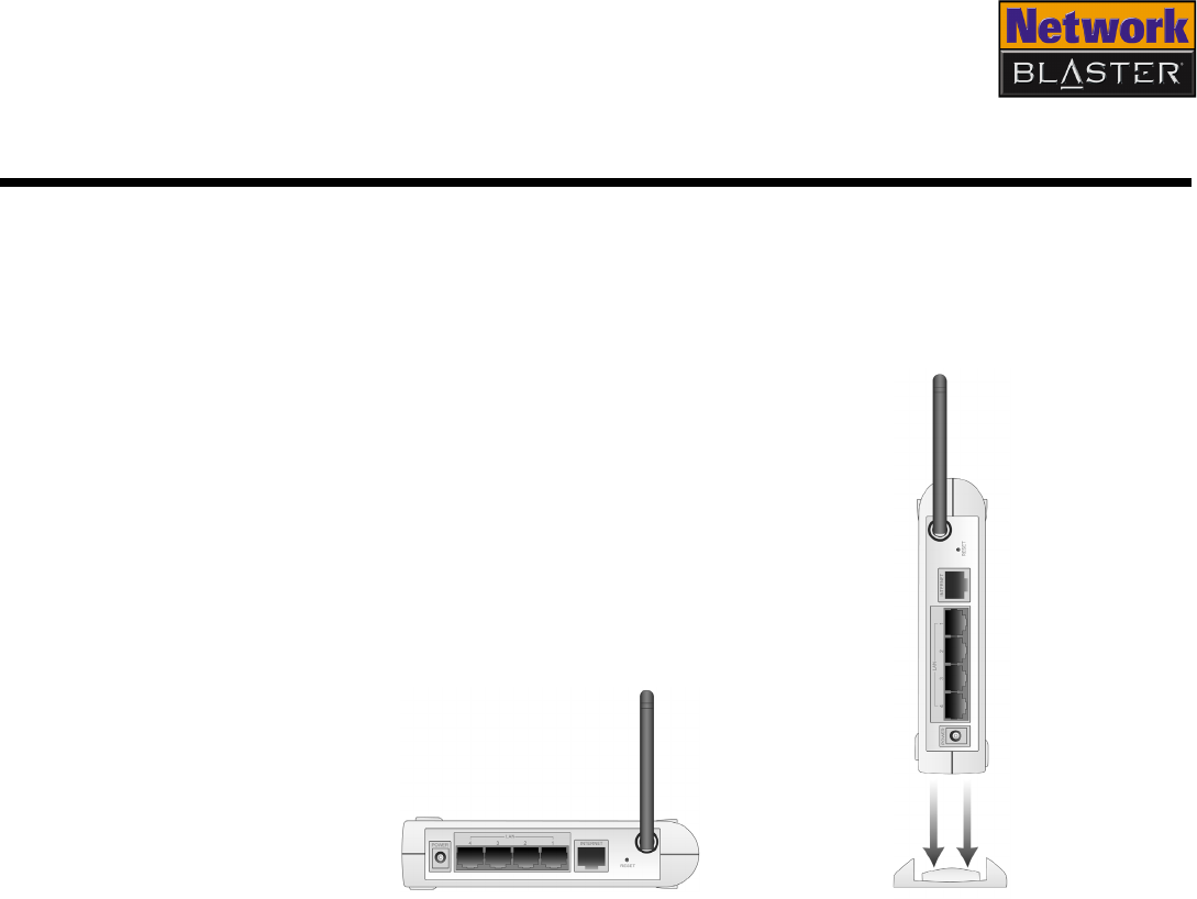
1. Before you begin, choose the best location for your Wireless AP Router. For
optimal reception and performance, place the Wireless AP Router in the center
of your wireless LAN, on a flat horizontal surface, and where there is minimum
obstruction between wireless clients and the Wireless AP Router.
2. Position the antenna such that it points up, and attach the optional stand if
you want to place your Wireless AP Router upright.
Figure 3-1
OR
Setting Up Your Wireless AP Router 3-2
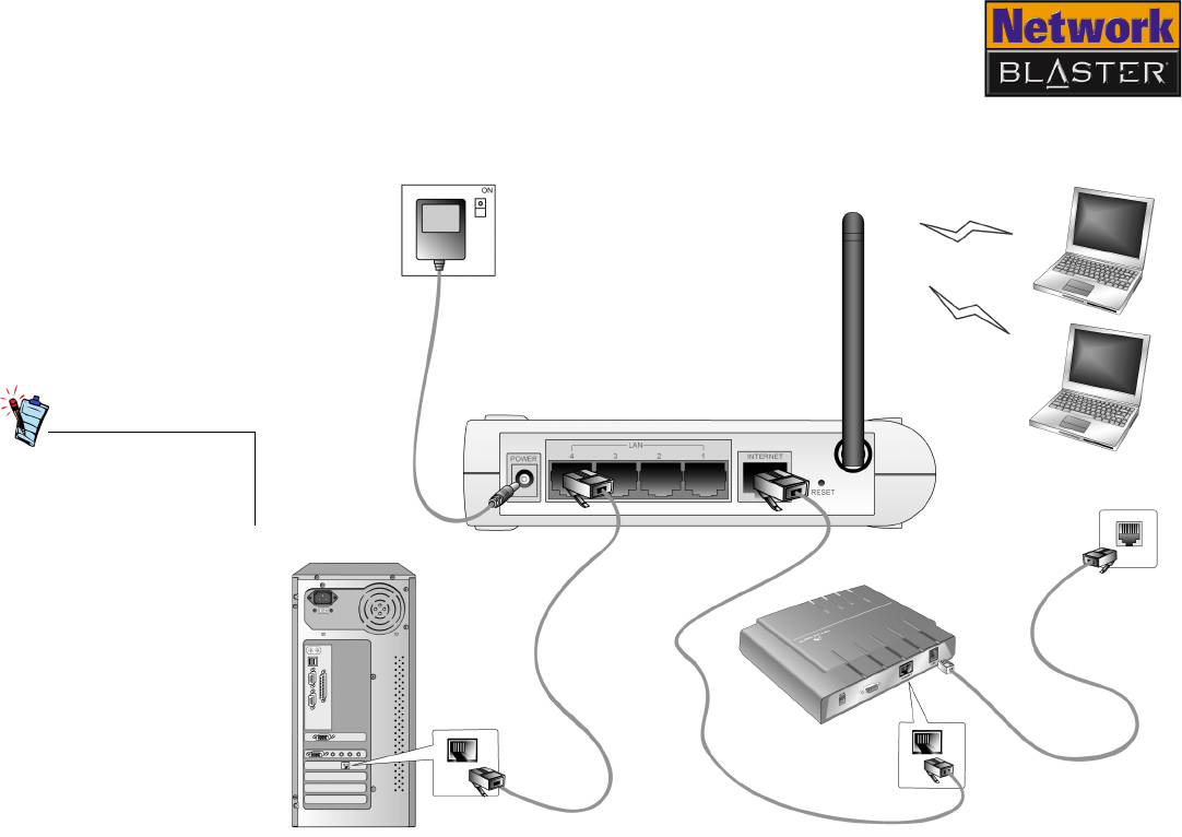
3. Set up your Wireless AP Router as shown in Figure 3-2.
Up to four computers can
be connected via wire to
your Wireless AP Router.
Figure 3-2
Wireless clients
Wireless AP Router
Power
adapter
RJ-45
Ethernet
cable
Ethernet port
DSL modem
or cable
modem
Power outlet
Wired client
(optional)
Wall
outlet
Ethernet port

Setting Up Your Wireless AP Router 3-3
4. Congratulations! Depending on your hardware configuration, you should be
able to access the Internet from any wired or wireless client connected to your
Wireless AP Router right away.
If not, additional steps may be required to set up your Wireless AP Router
properly. The following chapter, "Configuring Basic Settings", leads you
through these steps. It also shows you how to enable the powerful security
features of your Wireless AP Router, in order to prevent unauthorized users
from accessing your network.
Although not essential to
operation, configure your
security settings after
setting up your Wireless
AP Router to safeguard the
data exchanged within
your network.

Configuring Basic Settings

Configuring Basic Settings 4-1
Configuring Basic Settings
This chapter guides you through the steps required to access your Wireless AP
Router’s configuration page, and thereafter, to configure its basic settings.
Please note that manually configuring your Wireless AP Router’s settings is not a
prerequisite for proper operation in all scenarios. If you connect to the Internet
using a cable modem, for example, it is very likely that you will be able to access
the Internet from any wired or wireless client connected to your Wireless AP
Router, immediately after it has been properly set up (see Chapter 3, “Setting Up
Your Wireless AP Router”).
You should therefore only attempt to configure your Wireless AP Router’s settings
if:
• you are unable to access the Internet from a computer connected (via wire or
wirelessly) to your Wireless AP Router; or
• you would like to enable your Wireless AP Router’s security features.
If you are already able to access the Internet from a client, proceed to "Accessing
the configuration page" on page 4-5.
The arrangement of
information in this chapter
is designed to benefit
users who are new to
networking.
If you are an experienced
user, proceed directly to
"Accessing the
configuration page" on
page 4-5 and
subsequently to
"Configuring Internet
connection settings" on
page 4-8 to learn more
about the configuration
options available for each
protocol.

Configuring Basic Settings 4-2
Step 1:
Preparing a
client
You can access your Wireless AP Router’s configuration page using any computer
on your wired or wireless LAN. Whichever you choose, you must first make sure
that the computer can communicate with your Wireless AP Router. To do this, you
need to configure the computer to obtain an IP address from your Wireless AP
Router and to ensure that a valid IP address has been assigned to your network
interface card (NIC).
The default settings of your Wireless AP Router are:
❑IP address: 192.168.2.1
❑Subnet Mask: 255.255.255.0
For more information, see "Configuring your wired client" below or "Configuring
your wireless client" on page 4-4.
Configuring your
wired client
The following steps also apply if you are configuring a wireless client, but an
additional step is required before proceeding. See “Configuring your wireless
client” on page 4-4 for more information.
In Windows
2000/XP
1. Click Start → Settings → Control Panel or Start → Control Panel.
2. For Windows XP users, double-click the Network Connections icon.
For Windows 2000 users, click the Network and Dial-Up Connections icon.
3. Right-click the Local Area Connection icon and then click Properties.
4. When the Local Area Connection Properties dialog box appears, select
Internet Protocol (TCP/IP) and then click the Properties button.
5. When the Internet Protocol (TCP/IP) Properties dialog box appears, click
the Obtain an IP address automatically option.
6. Click the OK button.
7. When the Local Area Connection Properties dialog box appears, click the
OK button.
Make sure that the
computer you are
using has a functioning
network interface card
(NIC).

Configuring Basic Settings 4-3
To check the IP address assigned to your NIC
1. Click Start → Programs (or All Programs, if you are in Windows XP Start
menu mode) → Accessories → Command Prompt.
2. When the Command Prompt dialog box appears, type ipconfig and press
the <ENTER> key. Verify that your IP address is 192.168.2.xxx and your
Subnet Mask is 255.255.255.0.
If they are not, go to steps 3 and 4 below.
3. Type ipconfig/release and press the <ENTER> key.
4. Type ipconfig/renew and press the <ENTER> key.
Your IP address and Subnet Mask change to the above values.
In Windows 98
SE/Me
1. Click Start → Settings → Control Panel.
2. Double-click the Network icon.
3. When the Network dialog box appears, click the Configuration tab.
4. Click the name of your Ethernet card, for example, TCP/IP->PRO/100+
Management Adapter (10/100) and then click the Properties button.
5. When the TCP/IP Properties dialog box appears, click the IP Address tab.
6. Click the Obtain an IP address automatically option to select it and click
the OK button.
7. Click the OK button.
8. When Windows prompts you to restart your computer, click the Yes button.
The computer restarts.
To check the IP address assigned to your NIC
1. Click Start → Run.
2. When the Run dialog box appears, type winipcfg in the Open box, then click
the OK button. The next dialog box may take a minute or two to appear, so do
not restart your computer or abort this operation prematurely.

Configuring Basic Settings 4-4
3. In the IP Configuration dialog box that appears, click the arrow next to the
first box and then click the name of your network device to select it. Verify
that your IP address is 192.168.2.xxx and your Subnet Mask is
255.255.255.0.
If they are not, go to steps 4 and 5 below.
4. Click the Release button and then click the Renew button. Your IP address
and Subnet Mask change to the above values.
5. Click the OK button to close the IP Configuration dialog box.
Configuring your
wireless client
Your wireless adapter is the wireless equivalent of an NIC. Preparing a computer
on a wireless LAN is, therefore, similar to preparing a computer on a wired LAN.
Before performing the steps presented in "Configuring your wired client" on page
4-2, however, ensure that the wireless settings of your computer’s wireless
adapter match the default wireless settings of your Wireless AP Router, namely:
❑Operation Mode: Infrastructure
❑SSID: Network Blaster
❑Authentication: Open
❑WEP Mode: Disabled
Refer to the User’s
Guide of your
computer’s wireless
adapter if you need
instructions on
changing its wireless
settings.

Configuring Basic Settings 4-5
Step 2:
Configuring
basic settings
on your
Wireless AP
Router
After preparing a computer, you can configure the basic settings of your Wireless
AP Router using a web browser.
Disabling the proxy
setting in your web
browser
To access your Wireless AP Router’s configuration page, the HTTP Proxy feature in
your web browser has to be disabled.
To disable the HTTP Proxy feature in Internet Explorer:
1. Start Internet Explorer and click the Stop button.
2. Click the Tools menu option and then click Internet Options to select it.
3. In the Internet Options dialog box that appears, click the Connections tab.
4. Click the LAN settings button.
5. Clear all the check boxes.
6. Click the OK button in the next two dialog boxes that appear to complete
disabling the HTTP Proxy feature.
Accessing the
configuration page
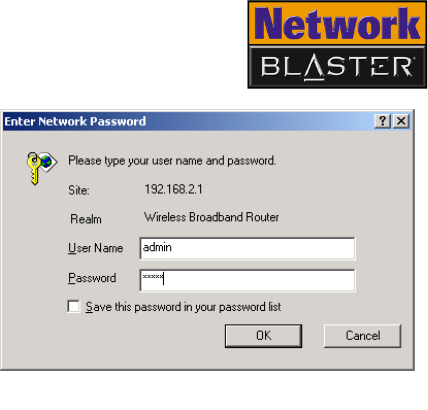
1. On the computer that you have prepared, open a web browser such as
Internet Explorer or Netscape.
2. Type http://192.168.2.1 in the Address (for Internet Explorer) or
Location (for Netscape) box and press the <ENTER> key.

Configuring Basic Settings 4-8
Configuring
Internet
connection
settings
In order for your Wireless AP Router to access the Internet, its Internet connection
settings have to be configured to suit the protocol that your broadband modem
uses to connect to the Internet.
If you connect to the Internet using a DSL Modem, and the use of your account
requires entering a login name and password, your ISP uses PPPoE. See “PPPoE
connection” on page 4-9.
If you connect to the Internet using a cable modem, your ISP probably uses DHCP.
See “DHCP connection” on page 4-10.
If you connect to the Internet using a DSL Modem, and the use of your account
requires you to manually enter your IP address, subnet mask, default gateway and
DNS servers, see "Fixed IP connection (using static IP address)" on page 4-11.
These Internet
connection
settings depend on
your subscription
with your Internet
Service Provider
(ISP). If you are
not sure of your
configuration,
check with your
ISP.
Configuring Basic Settings 4-9
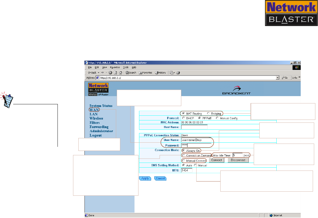
PPPoE connection If you connect to the Internet using a DSL Modem, and the use of your account
requires entering a login name and password, select the PPPoE option in the
Protocol field.
After you have
updated the various
settings, make sure
you click the Apply
button for changes to
take effect.
Figure 4-3
Click this link to
view this page.
Always On option
Allows a PPP session to be
kept online continously.
Max Idle Time
Determines the time before
automatic disconnection
during inactivity.
Manual Connect option
Allows an instant connection by clicking the
Connect button. Click the Disconnect
button to terminate the session.
Connect on Demand
option
Allows any client PC
requesting for connection to
dial the ISP automatically
through the AP router. To end
the session manually, click
the Disconnect button.
User Name/Password
Type the Use rna me and
Password given by your ISP.
Select NAT Routing or
Bridging to configure your
computer network.
Configuring Basic Settings 4-10
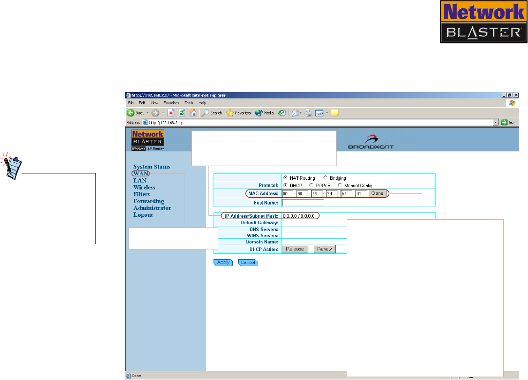
DHCP connection If you connect to the Internet using a cable modem, select the DHCP option in the
Protocol field.
After you have
updated the various
settings, make sure
you click the Apply
button for changes to
take effect.
Figure 4-4
Click this link to view
this page.
IP Address/Subnet Mask
Displays the IP Address and Subnet Mask
that is obtained automatically from the
ISP.
MAC Address
A MAC (Media Access Control) Address is a
unique hexadecimal identification number
given to each network device.
Some ISPs register your network card’s
MAC Address. If the registered MAC
address does not match that of the
network device connected to their servers
(such as your Wireless AP Router, which
has a different MAC address), connection
will fail. In such situations, copy the MAC
address of your network card to the MAC
Address box.
Contact your ISP if you are unable to
establish a connection even after typing
the correct MAC Address into the MAC
Address box.
Configuring Basic Settings 4-11
Fixed IP connection
(using static IP
address)
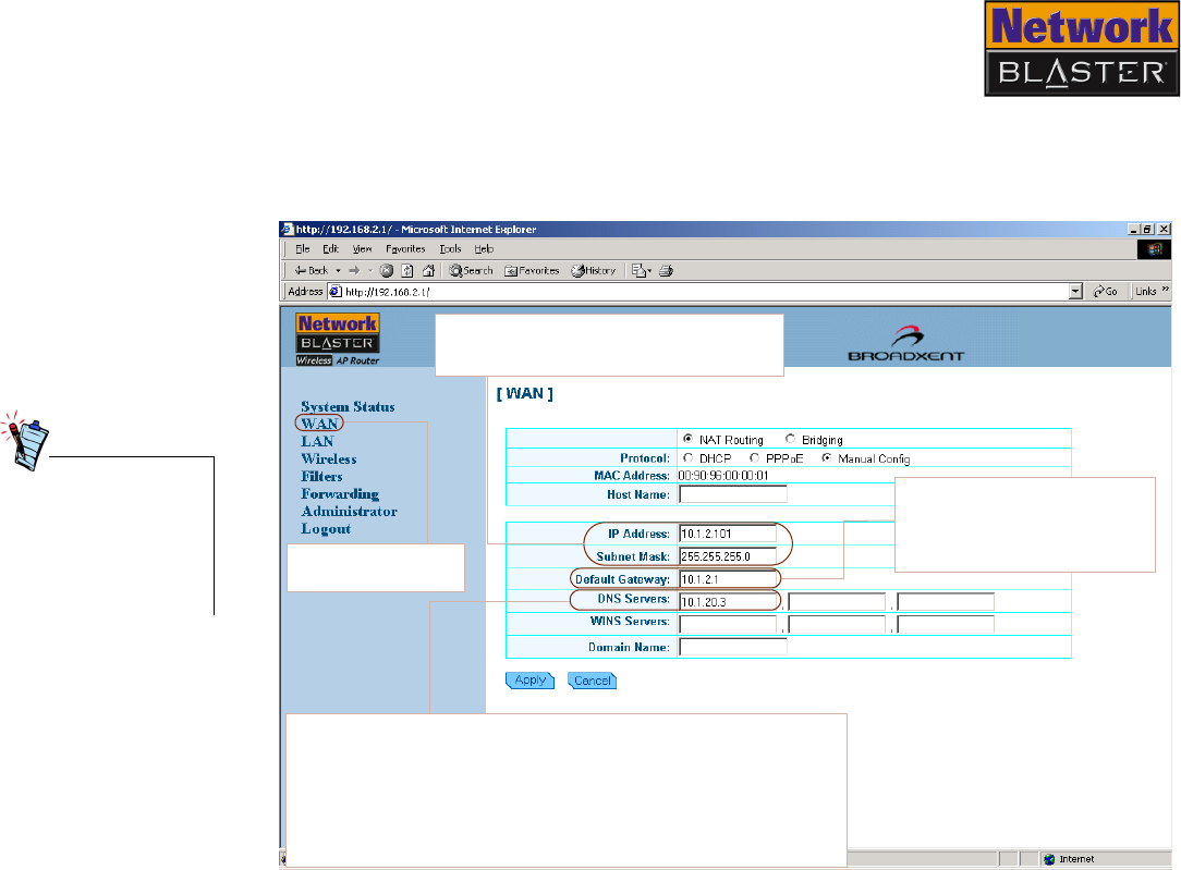
If you connect to the Internet using a DSL Modem, and the use of your account
requires you to manually enter your IP address, subnet mask, default gateway and
DNS servers, select the Manual Config option in the Protocol field.
After you have
updated the various
settings, make sure
you click the Apply
button for changes to
take effect.
DNS Servers
A Domain Name Server (DNS) is an index of names and Web addresses.
When you type a Web address into your browser, such as
www.whitehouse.gov, a DNS server will find that name in its index and
then find the matching IP address: 198.137.240.92. Most ISPs provide
a DNS server for speed and convenience. Since you are connecting to
the Internet with static IP settings, it is likely that your ISP also
provided DNS server addresses.
Figure 4-5
Click this link to view
this page.
IP Address/Subnet Mask
Type the fixed IP address and its associated
subnet mask provided by your ISP.
Default Gateway
Allows you to set up the default
gateway on the WAN interface of
your router. Type the gateway IP
address provided by your ISP.
Configuring Basic Settings 4-12
Configuring
Wireless LAN
settings
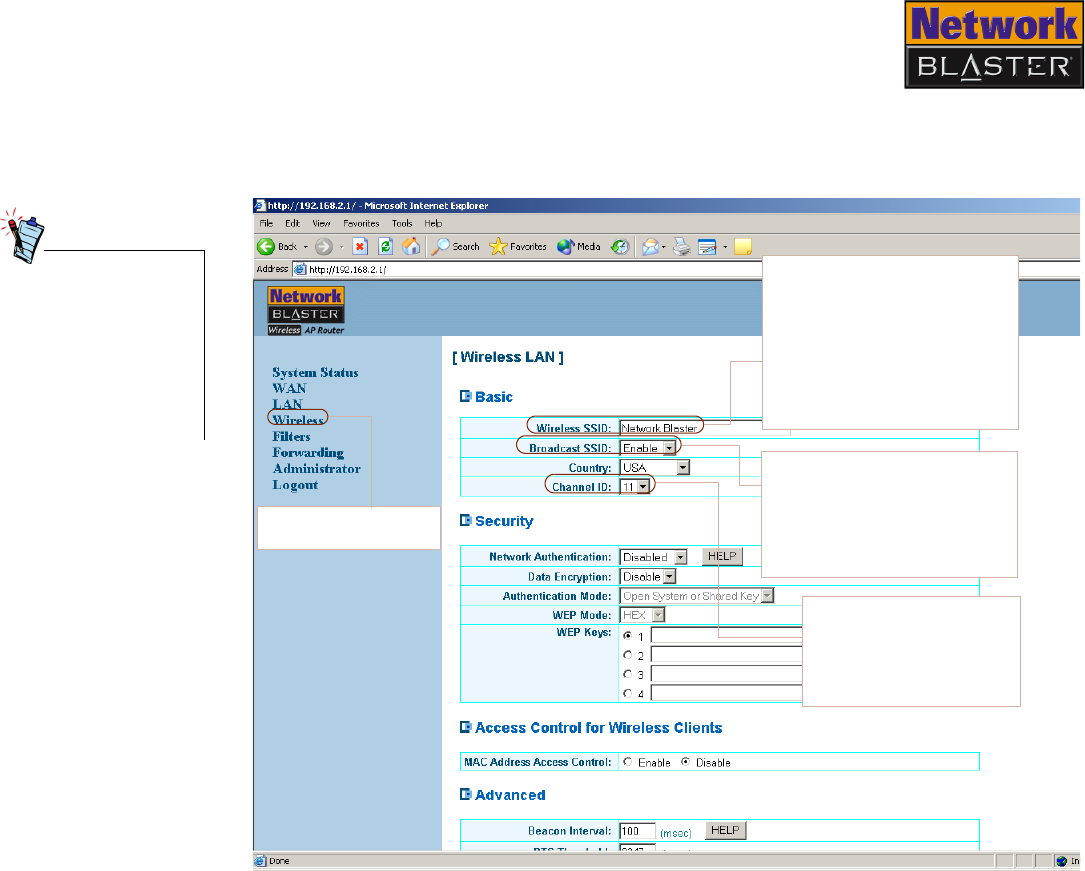
The Wireless LAN page is where you configure the wireless LAN settings of your
Wireless AP Router. Refer to Figure 4-6 to learn more about configuring these
settings.
Although not essential
to operation, configure
your Wireless LAN
settings after setting
up your Wireless AP
Router to avoid conflict
with other wireless APs
in the vincinity.
Figure 4-6
Click this link to view
this page.
Broadcast SSID
If you enable this, your Wireless
AP Router will broadcast its SSID
to all wireless clients in the vicinity.
Disable this if you want your
Wireless AP Router’s SSID to be
invisible to wireless clients.
Channel ID
To avoid interference with
other Wireless AP Routers,
select a channel ID that is
different from other Wireless
AP Routers in the vicinity.
Wireless SSID
A name that identifies a wireless
LAN. It is recommended that you
change your Wireless AP Router’s
SSID so that your wireless LAN can
easily be distinguished from others
in the vincinity. All wireless clients
communicating with your Wireless
AP Router must have the same
SSID as your Wireless AP Router.

Configuring Basic Settings 4-13
Configuring
Wireless Security
settings
Your Wireless AP Router supports two main wireless security standards: Wired
Equivalent Privacy (WEP) and Wi-Fi Protected Access-Pre Shared Key (WPA-PSK).
WEP is usually sufficient for simple wireless deployments (such as home or small
office environments) where network use is casual and traffic, light. In
environments where data security is of paramount importance, however, WPA-PSK
is recommended because of its stronger encryption algorithm.
To configure WEP settings, see "Wired Equivalent Privacy (WEP)" on page 4-14.
To configure WPA-PSK settings, see "Wi-Fi Protected Access-Pre Shared Key
(WPA-PSK)" on page 4-15.
Note: Your Network Blaster Wireless 802.11g Router is backward compatible with 802.11b.
The 802.11b or 802.11g security options available for you to choose from depend on your
wireless client’s capabilities.
Although not essential
to operation, configure
your Wireless Security
settings after setting
up your Wireless AP
Router to safeguard
the data exchanged
within your network.
Configuring Basic Settings 4-14
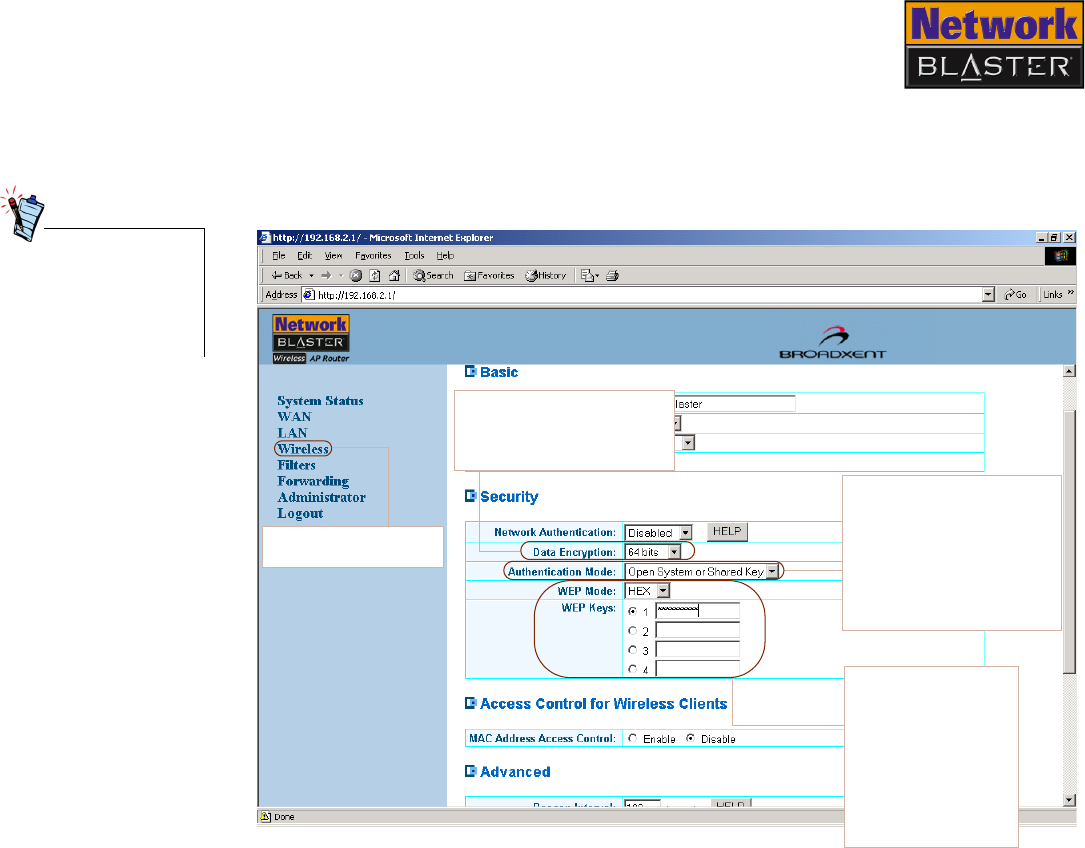
Wired Equivalent
Privacy (WEP)
Wired Equivalent Privacy (WEP) is a data stream encryption technology that allows
you to define up to four keys shared between APs and wireless clients.
Unauthorized wireless clients that do not have the same keys are locked out. Refer
to Figure 4-7 to learn more about configuring these settings.
For more information
about configuring WEP
settings, see "About
Network Security" on
page B-1.
Authentication Mode
Select Open System or
Shared Key to allow any
wireless client to join your
wireless LAN. Select Shared
Key only to allow wireless
clients with the same WEP
keys to join your wireless
LAN.
Data Encryption (WEP)
Enables or disables WEP
encryption.
Figure 4-7
Click this link to view
this page.
WEP Mode/Keys
Specify hexadecimal
or ASCII WEP keys (64
or 128 bits) to be used
for encryption. 64-bit
keys have 10 hex or 5
ASCII characters;
128-bit keys have 26
hex or 13 ASCII
characters.
Configuring Basic Settings 4-15
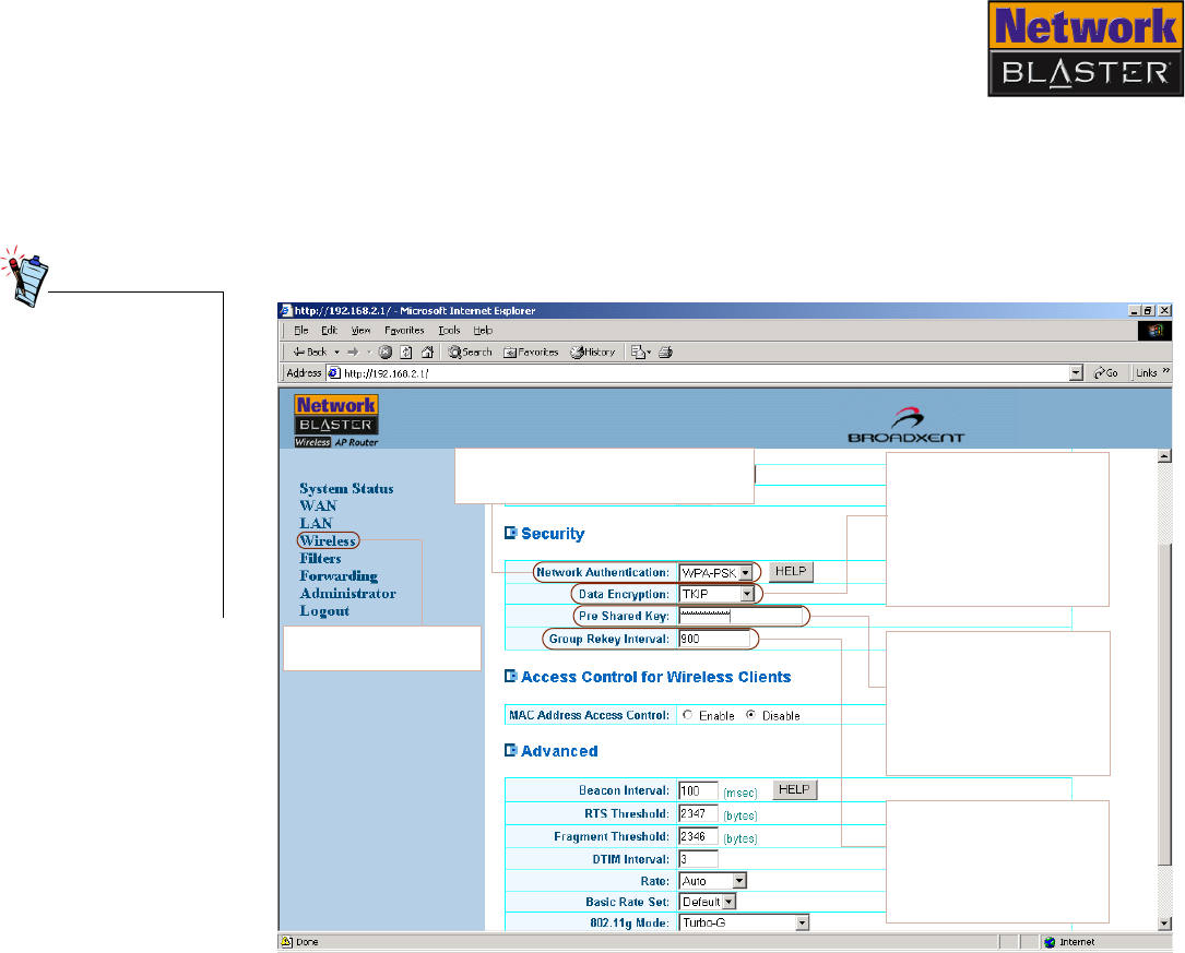
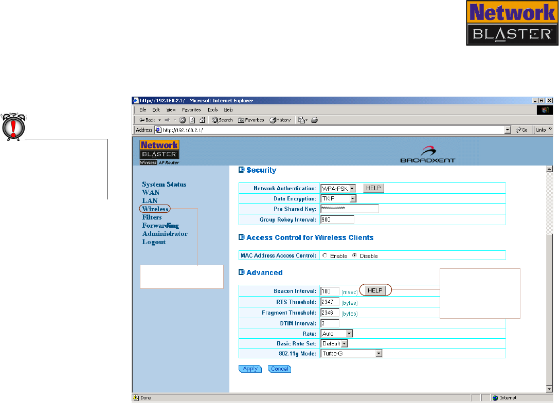
Wi-Fi Protected
Access-Pre Shared
Key (WPA-PSK)
Conceived to address the vulnerabilities of WEP, Wi-Fi Protected Access-Pre Shared
Key (WPA-PSK) affords you a simple yet powerful way of securing your wireless
network. Its Temporal Key Integrity Protocol (TKIP), which generates up to five
hundred trillion unique data encryption keys derived from a single Pre Shared Key,
makes it difficult - if not impossible - for aspiring intruders to gain access to your
network by obtaining a common key. Refer to Figure 4-8 to learn more about
configuring these settings.
• Some wireless
clients may not
support WPA
encryption because
WPA is a relatively
new technology. In
these cases, use
WEP encryption
instead.
•Windows XP has a
built-in client that
supports WPA
encryption.
Figure 4-8
Network Authentication
Enables or disables WPA-PSK. Data Encryption
Select a data encryption
mode from the
drop-down list box: TKIP,
Advanced Encryption
Standard (AES) or a
combination of both
(TKIP + AES).
Group Rekey Interval
Sets the time taken (in
msec) for AES or TKIP to
dynamically generate a
new unique encryption
key.
Pre Shared Key
Specify a password to
launch the encryption
process. All wireless
clients connected to your
network have to share
this password.
Click this link to view
this page.

Configuring Advanced Settings
Configuring Advanced Settings 5-1
Configuring Advanced Settings
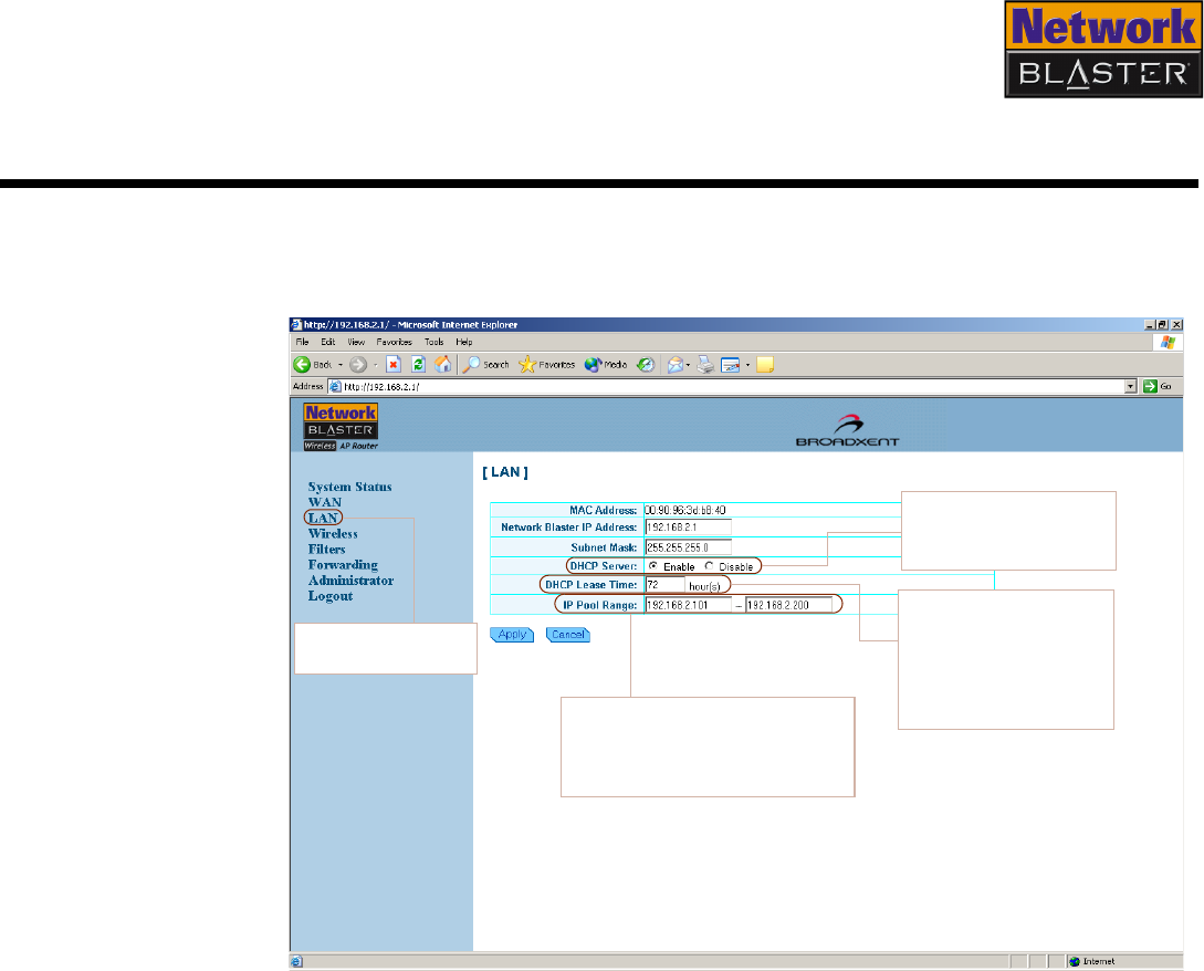
Configuring LAN
settings
The Local Area Network (LAN) page is where you configure the LAN settings of
your Wireless AP Router. Refer to Figure 5-1 to learn more about configuring these
settings.
Figure 5-1
Click this link to view
this page.
DHCP Server
Lets you enable or disable
your Wireless AP Router
DHCP server.
IP Pool Range
Specifies the range of IP addresses
that can be assigned to clients when
you enable your Wireless AP Router
DHCP server.
DHCP Lease Time
Lets you set the usage
duration of an IP address
that can be reserved for a
client when you enable
your Wireless AP Router
DHCP server.
Configuring Advanced Settings 5-2
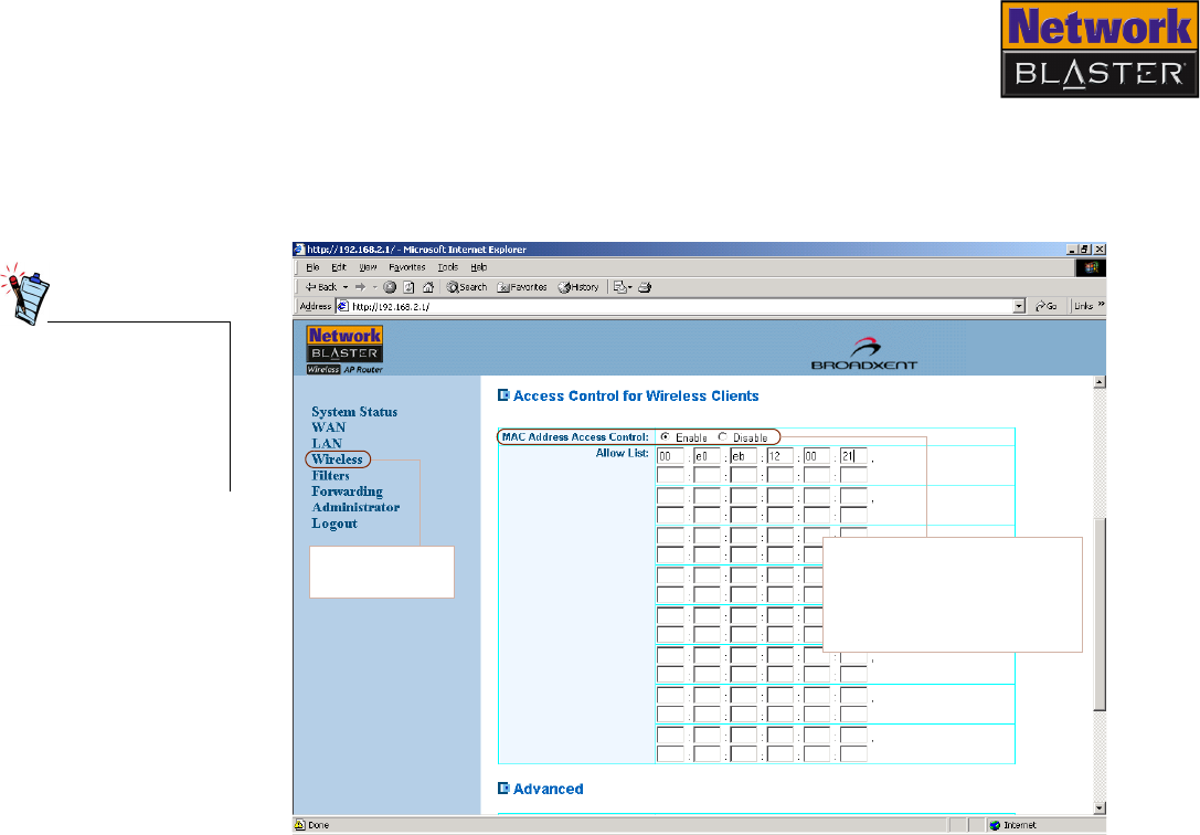
Configuring
Wireless MAC
Address Access
Control
If you want to customize security settings, go to the Access Control section shown
in Figure 5-2. By controlling MAC address access, you can determine which
wireless clients have access to your wireless LAN. Refer to Figure 5-2 to learn more
about configuring these settings.
Network devices, such
as USB adapters,
PCMCIA cards, DSL
modems and PCI
ethernet cards, have
labels displaying a
MAC address.
MAC Address Access Control
Enter the MAC address of the
network devices that you want
to allow access to your Wireless
AP Router in the Allow List
boxes.
Click this link to
view this page.
Figure 5-2
Configuring Advanced Settings 5-3
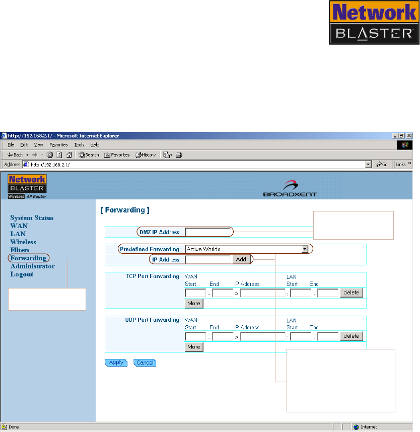
Configuring
Forwarding
settings
If you want Internet users to access your LAN, you can use either De-Militarized
Zone (DMZ) or Port Forwarding.
For DMZ, enter your PC server IP address.
For Port Forwarding, select the applications for predefined ports. Alternatively, you
can also specify your own port.
DMZ IP Address
Type the LAN server
IP address here.
Click this link to
view this page.
Figure 5-3
Predefined forwarding
Select an application from the
list, type the LAN server IP
address in the IP address
field, and then click the Add
button to add the predefined
ports.
Configuring Advanced Settings 5-4
Configuring
Wireless Advanced
settings
If you want to customize settings to fine-tune your wireless LAN performance on
certain networks, go to the Advanced section shown in Figure 5-4.
Do not change these
settings if you are
unsure about how to
configure advanced
settings.
Click this link to view
this page.
Figure 5-4
HELP
Click the HELP
button for more
information on these
parameters.
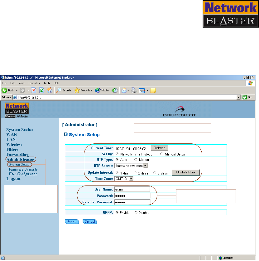
Configuring Advanced Settings 5-5
Changing router
web page access
password
If you want to change the username and password needed to gain access to
administrator settings, go to the System Setup section. Calendar settings can also
be customized here. Refer to Figure 5-5 to learn more about configuring these
settings.
Figure 5-5
Click the
Administrator link
and then the System
Setup link to view
this page.
Change your User Name
and Password here.
Configure calendar settings here.
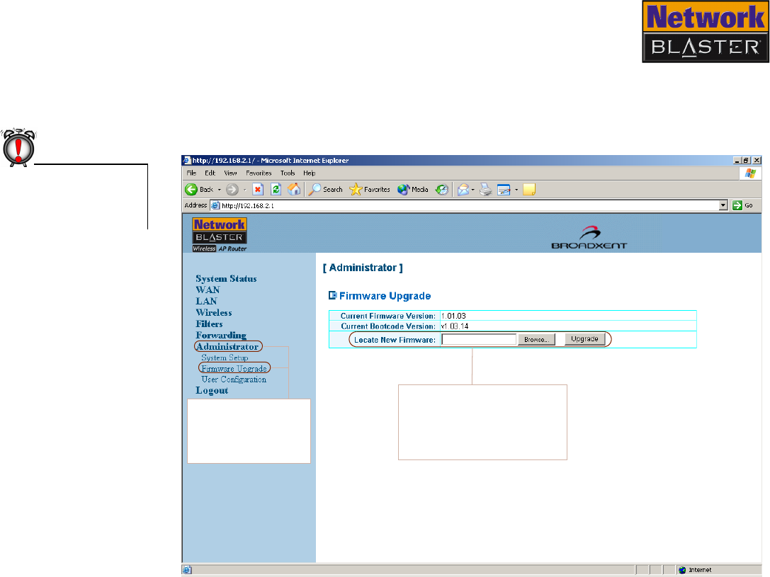
Configuring Advanced Settings 5-6
Upgrading
Firmware
If you want to upgrade the firmware settings of your Wireless AP Router, go to the
Firmware Upgrade section. Current firmware and bootcode versions are also
shown here. Refer to Figure 5-6 to learn more about configuring these settings.
Do not turn off your
Wireless AP Router
when upgrading the
firmware.
Figure 5-6
Locate New Firmware
Lets you locate and upgrade to
new firmware. Click the Browse
button to locate and select your
firmware, and click the Upgrade
button.
Click the
Administrator link
and then the
Firmware Upgrade
link to view this page.
Configuring Advanced Settings 5-7
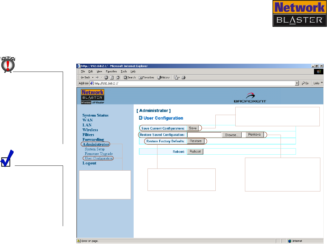
Restoring or saving
a profile
If you want to save settings or recall saved group settings quickly, go to the User
Configuration section. Default settings can also be restored here. Refer to Figure
5-7 to learn more about configuring these settings.
Resetting your
Wireless AP Router will
erase all of your
configured settings
(LAN, wireless LAN,
WEP, etc.) and replace
them with the factory
defaults. Do not reset
your Wireless AP
Router if you want to
retain your settings.
You can also reset your
Wireless AP Router by
pressing the RESET
button on your
Wireless AP Router.
Refer to "Resetting the
Wireless AP Router" on
page 5-8 for details.
Figure 5-7
Save Current Configurations
Saves current configuration settings
for future use or backup purposes.
Restore Saved Configurations
Lets you load previously saved
configuration settings. Click the
Browse button to select a
configuration file, and then click
the Retrieve button.
Restore Factory Defaults
Click the Restore button to
reset your Wireless AP Router
to its factory defaults.
Click the
Administrator link
and then the User
Configuration link to
view this page.
Configuring Advanced Settings 5-8
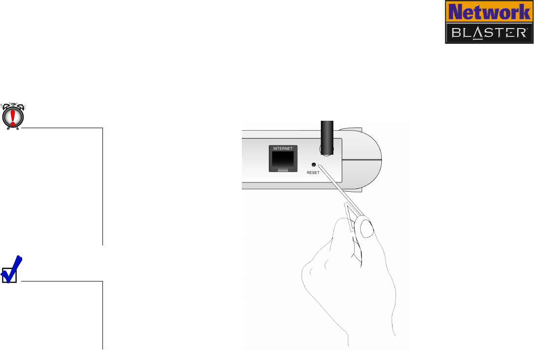
Resetting the
Wireless AP
Router
To reset your Wireless AP Router to its factory defaults, use a straightened
paperclip to press the RESET button while turning your Wireless AP Router off and
then on again. Keep the RESET button depressed throughout. Continue pressing
the RESET button for another 10 or more seconds before releasing it.
Resetting your
Wireless AP Router will
erase all of your
configured settings
(LAN, wireless LAN,
WEP, etc.) and replace
them with the factory
defaults. Do not reset
your Wireless AP
Router if you want to
retain your settings.
You can also reset your
Wireless AP Router
with your web browser.
Refer to "Restoring or
saving a profile" on
page 5-7 for details.
Figure 5-8

About Wireless LANs

About Wireless LANs A-1
About Wireless LANs
Wireless LANs are a revolutionary way of connecting devices to each other. In a
wireless LAN, information is transmitted using radio waves. This means that you
can establish a network of wireless devices in a room or across different rooms
without linking the devices with wires and cables.
Depending on your needs, a wireless LAN can be the sole network solution, or an
extension of a wired LAN.
Features and
Benefits of
Wireless LANs
Using wireless LANs has many advantages:
❑Convenience, cost effectiveness and flexibility
Setting up a wireless LAN is easy, fast and cost effective as you do not need to install
additional wiring.
❑Mobility
Unlike wired LANs, a wireless LAN allows you to move around and still remain connected
to the network.
❑Scalability
You can choose to configure your wireless LAN in Ad-hoc mode or Infrastructure mode. In
Ad-hoc mode, a wireless client can communicate with other wireless clients directly. In
Infrastructure mode, one or more wireless clients are connected to an access point (AP)
router, and this AP router connects these wireless clients to other wireless and wired
clients. See "About Ad-Hoc Mode" on page A-2 and "About Infrastructure Mode" on page
A-3 for more information.
About Wireless LANs A-2
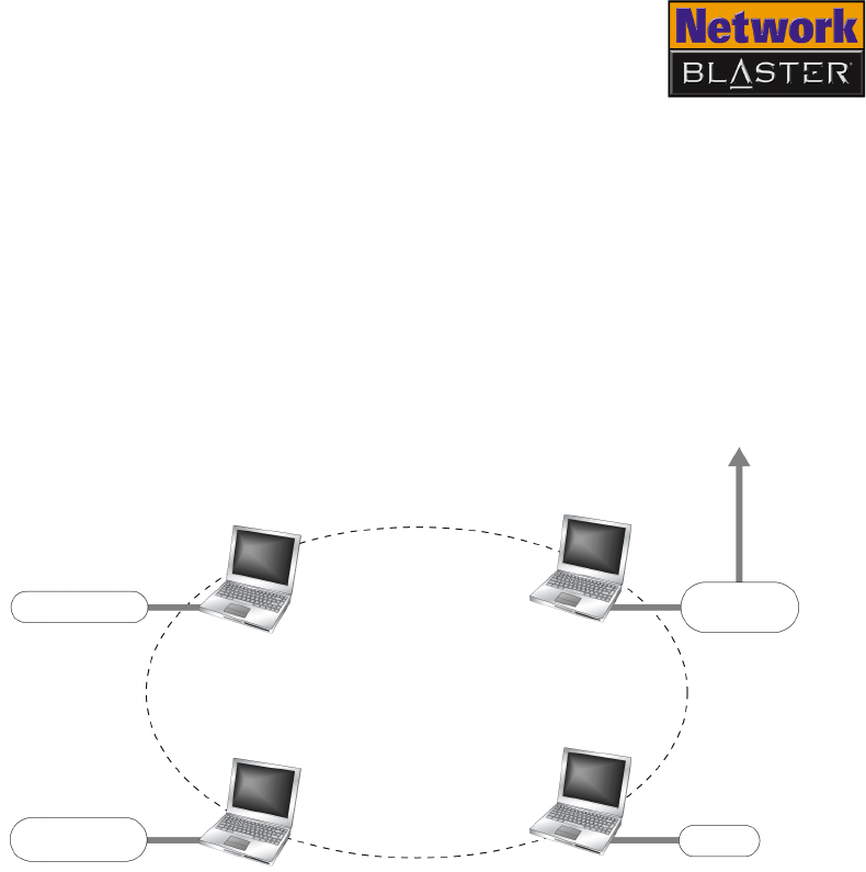
About Ad-Hoc
Mode
Ad-hoc mode allows for wireless-to-wireless communication. Wireless clients
connected in this way can share files, printers, drives and other resources, as well
as access the Internet using a shared modem. However, a wireless client can only
communicate with other wireless clients that:
❑are part of the same wireless LAN workgroup
❑share the same IEEE 802.11 standard
❑are within a fixed range
Ad-hoc mode is also known as Peer-to-Peer mode.
Figure A-1: Ad-hoc Network
Printer
Broadband
modem
DVD-ROM drive
Internet
Wireless LAN
External hard
disk drive
About Wireless LANs A-3
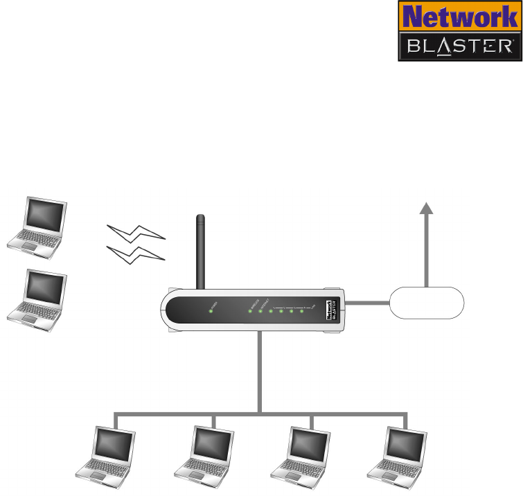
About
Infrastructure
Mode
In Infrastructure mode, a wireless client communicates with other wired and
wireless clients through an AP router. A wireless client connected in this way can
access resources of Ethernet or wireless LANs connected to the AP router, including
access to the Internet using a shared modem.
Figure A-2: Infrastructure Network
Wireless AP Router
Wired LAN
Wireless clients
Internet
Broadband
modem

About Wireless LANs A-4
Setting Up
Wireless LANs
When setting up a wireless LAN, take note of the following points:
❑Start by determining the areas to be networked, the number of users and the type of
devices to be used. Then determine if you require AP routers and where they should be
placed.
❑If two AP routers are placed close to each other, you can optimize your bandwidth by
setting them to different channels.
❑Radio waves can pass through walls and glass but not metal. If the signal on the other
side of a wall is weak, it may be that the wall has reinforcing metal in its structure. Install
another AP router to circumvent this problem or move your AP router to another location.
❑Floors usually have metal girders and metal reinforcing struts that impede radio waves.

Frequently Asked Questions

Frequently Asked Questions B-1
Frequently Asked Questions
Turbo-G Your Creative wireless device comes equipped with Turbo-G™ technology,
which improves your device's performance by 35%, without affecting that of
other wireless local area network (WLAN) devices in the neighbourhood. By
installing a few Turbo-G capable devices in the network, overall networking
speed can be dramatically improved. Turbo-G technology is fully compliant
with 802.11g and 802.11b standards.
When using a Turbo-G capable device to surf the Internet
wirelessly, why is there no speed improvement?
Turbo-G capable devices do not affect your Internet connection speed. Your
Internet connection speed depends on your modem and your Internet service
plan. It is unrelated to your use of Turbo-G devices.
Will my wireless networking speed slow down when a non-Turbo-G
capable device joins the wireless network?
Your wireless networking speed may slow down when a non-Turbo-G capable
device joins your wireless network. Your Turbo-G capable device, however, will
always continue to maintain a higher performance speed than standard
802.11g or 802.11b devices.

Frequently Asked Questions B-2
How do I obtain maximum wireless networking performance?
Make sure that your access point and wireless client are Turbo-G capable.
Disable your wireless security options (for example, Wired Equivalent Privacy,
Advanced Encryption Standard or WiFi Protected Access) in your web
configuration.

Technical Specifications

Technical Specifications C-1
Technical Specifications
Standards ❑IEEE 802.11g
❑IEEE 802.11b
❑IEEE 802.3
❑IEEE 802.3u
Interface ❑INTERNET port
IEEE 802.3u compliant 10/100Base-Tx RJ-45 port for Cable/DSL/Direct Ethernet
connection with HP Auto-MDIX support
❑LAN port
IEEE 802.3u compliant 10/100 Base-Tx RJ-45 Switch port with HP Auto-MDIX
Antenna ❑Internal diversity antenna (2.4 GHz)
❑External diversity antenna (2.4 GHz)
Frequency Band ❑2.4–2.4835 GHz
Data Rate ❑IEEE 802.11g: 54, 48, 36, 24, 18, 12, 9, 6 Mbps
❑IEEE 802.11b: 11, 5.5, 2, 1 Mbps
Channels ❑11 Channels (US, Canada), 13 Channels (Europe), 14 Channels (Japan)
Security ❑64 or 128-bit WEP encryption
❑WPA-PSK
Dimensions ❑Length: 37 mm
❑Width: 134 mm
❑Height: 170 mm

Glossary

Glossary E-1
Glossary
10 Base-T A wiring standard used for Ethernet networks that can transmit data at up to 10
Mbps transmission using baseband unshielded twisted pair cables. The maximum
cable length is 100 meters (330 feet).
Ad-hoc mode A small peer-to-peer network mode, in which wireless clients are connected to
each other directly without using an AP. Some of the wireless clients are part of the
network for a limited duration. They are also in close proximity with the rest of the
network. According to the IEEE 802.11b specification, Ad-hoc mode is referred to
as an independent basic service set.
Antenna A device that intercepts radio frequency (RF) waves from the atmosphere and
converts them to corresponding signal voltages.
AP (Access Point) A networking device that transparently bridges wireless computers to a wired local
network.
ASCII (American
Standard Code for
Information
Interchange)
ASCII is the most common format for text files in computers and on the Internet.
In an ASCII file, each alphabetic, numeric, or special character is represented with
a 7-bit binary number (a string of seven 0s or 1s). 128 possible characters are
defined.
Bandwidth A measure of the maximum rate of data transfer. A higher bandwidth allows more
data transmission in a given period of time. For digital services, the bandwidth is
usually expressed in bits or bytes per second.
Binary A number system that has only two digits, 0 and 1.

Glossary E-2
Bridge A hardware device that links two or more physical networks and manages the
transfer of data between these networks. The two networks connected can be alike
or dissimilar.
Broadband A transmission media that can handle the transmission of multiple messages at
different frequencies, at one time. Broadband signals use analog carriers.
BSS (Basic Service
Set)
A group of wireless clients and an AP using the same ID (SSID).
Channel A channel is a separate path through which signals can flow.
Client A program or computer that is connected to a wired or wireless network.
dBm (Decibels Per
Milliwatt)
A unit of measurement used to express relative difference in power or intensity,
relative to 1 mW.
DHCP (Dynamic
Host Configuration
Protocol)
A method of assigning a temporary IP address to a host, such as a computer,
connected on a specific network. With dynamic addressing, a particular host may
have a different IP address each time it connects to the network.
Digital Data expressed as a string of 0s and 1s. Each of these digits is referred to as a bit
(and a string of 8 bits that a computer can address individually as a group is a
byte).
DNS (Domain
Name System)
This allows you to specify a symbolic name, a meaningful and easy-to-remember
“handle”, instead of an IP address. The DNS is the way that Internet domain
names are located and translated into IP addresses.

Glossary E-3
DNS Server A server that contains both the English and numerical addresses of all computers
connected to the Internet. When you specify an e-mail or IP address using the
“English” domain name, the DNS server will return the corresponding numeric
address.
Domain Name A domain name locates an organization or other entity on the Internet.
Driver A program that a computer uses to control the operation of a peripheral device,
such as a keyboard, modem, monitor, card, or cable.
DSSS (Direct
Sequence Spread
Spectrum)
A digital modulation technique that spreads data transmissions across the entire
available frequency band in a pre-arranged scheme. Under DSSS, each bit of data
to be transmitted is encoded with a redundant pattern called a chip. The chipping
code is known only to the sending and receiving clients, making it difficult for an
intruder to intercept and decipher the encoded wireless data. DSSS is used in IEEE
802.11b networks.
Dynamic IP address See DHCP (Dynamic Host Configuration Protocol).
Encryption A procedure to convert a file from its original form to one that can be read only by
the intended recipient.
ESS (Extended
Service Set)
A group of wireless clients and multiple APs using the same ID (ESSID) form an
ESS.
ESSID (Extended
Service Set Identity)
An ASCII string that is used by a wireless network. Wireless clients with a different
ESSID from your network’s ESSID cannot connect to your network. An ESSID can
be as long as 32 characters.

Glossary E-4
Ethernet A LAN protocol that supports data transfer rates of 10 Mbps. It is a widely
implemented LAN standard that operates over the twisted pair or coaxial cable. A
version of Ethernet, called 100 Base-T (or FastEthernet), supports data transfer
rates of 100 Mbps.
FastEthernet An Ethernet specification with a speed of 100 Mbps (10 times faster than
10BaseT).
Fragmentation
Threshold
The size at which the transmitted data packets are fragmented. The range extends
from 256 to 2346 bytes.
Full duplex Simultaneous and independent data transmission, between two communicating
computers, in both directions.
Half duplex A data transmission system where two computers can send and receive data but in
which data transmission can occur in only one direction at a time.
Hexadecimal A number system with a base of 16. The 16 digits in the hexadecimal system are
0, 1, 2, 3, 4, 5, 6, 7, 8, 9, a, b, c, d, e, f.
Hub A device used for connecting nodes in a star topology, that is, all the nodes are
connected to a central hub. A passive hub simply organizes the wiring, while an
active hub, besides organizing the wiring, regenerates and retransmits the signals.
IEEE 802.11 A family of wireless network standards, which includes 802.11a, 802.11b,
802.11e, and 802.11g (draft). The original 802.11 standard was first approved in
1997 but was not very successful because it was relatively slow at 2 Mbps.
IEEE 802.11b A high-bit wireless network standard that works on the 2.4 GHz band and utilizes
DSSS (direct sequence spread spectrum) technology. It offers data bit rates of up
to 11 Mbps and the range is from 200 to 300 feet for maximum speed.

Glossary E-5
IEEE 802.11g (draft) A 802.11 standard for wireless networking hardware. The 802.11g draft standard
specifies a maximum data transfer rate of 54 Mbps, an operating frequency of 2.4
GHz, backward compatibility with 802.11b devices and WEP encryption for
security.
Infrastructure mode A LAN or other small network mode in which wireless clients are part of the
network and use one or more APs to connect to a wired network. Each AP is
connected to the Ethernet network using a standard Ethernet cable. In IEEE
802.11b specification, the infrastructure mode is referred to as the Basic Service
Set.
Interface The physical arrangement that supports the attachment of a device to a connector
or to another device.
IP (Internet
Protocol)
The standard protocol within TCP/IP that defines the basic unit of information by
breaking down data messages into packets, routing and transporting the packets
over networks, then reassembling the packets at their destination. IP corresponds
to the Network layer (layer 3) in the ISP/OSI model.
IP address The address for a computer on a TCP/IP network. The IP address identifies a
particular machine on a network. The format of an IP address is a 32-bit numeric
address written as four numbers separated by periods. Each number can be 0 to
255, for example, 11.160.10.240 is an IP address. Any machine connected to the
Internet is assigned an IP address.
ISM (Industrial,
Scientific and
Medical) band
There are four unlicensed bands for wireless networks and these bands are
commonly known as ISM bands. These bands are found on the 900 MHz, 2.4 GHz
and 5 GHz (two) frequency bands.
KB (Kilobytes) 1 KB equals 1,024 bytes.

Glossary E-6
Kbps (Kilobits Per
Second)
A measure of data transfer speed.
LAN (Local Area
Network)
A computer network that spans a relatively small area. Most LANs are confined to
an office, single building, or group of buildings.
LED (Light Emitting
Diode)
An electric component that emits light (turns ON) when current flows through it.
MAC (Media Access
Control) address
A unique number that is assigned by manufacturers to each Ethernet network
device. A MAC address lets a network identify Ethernet network devices at the
hardware level.
Mbps (Megabits Per
Second)
A measure of data transfer speed.
Megabits/Megabytes One million bits/bytes.
Modem A device that allows a computer to transmit data to other computers.
NAT (Network
Address Translation)
An Internet standard that enables a LAN to use one set of IP addresses for internal
traffic and a second set of IP addresses for external traffic. NAT provides a type of
firewall security by hiding internal IP addresses. Since they are used internally,
such IP addresses will not be in conflict with those used by other companies and
organizations.
Network Mask See Subnet Mask.

Glossary E-7
NIC (Network
Interface Card)
A card that is installed in a computer so that it can be connected to a network. The
NIC manages the flow of network information to and from the computer.
PCMCIA (Personal
Computer Memory
Card International
Association)
An industry group organized in 1989 to promote standards for a card-size memory
or I/O device that would fit into a personal computer.
PCMCIA Card A card-size memory or I/O device that connects to a personal computer. The
PCMCIA card has a 68-pin connector that connects into a slot in the computer.
PING (Packet
Internet Groper)
An Internet program used to determine whether a specific IP address is accessible.
It works by sending a packet to the specified address and waiting for a reply. PING
is used primarily to troubleshoot network connections.
Preamble A preamble is a signal, in the form of series of pulses, used in network
communication to synchronize the transmission timing between two or more
systems. There are two options, Short and Long. The Short option improves
throughput performance.
Protocol A set of agreed-upon rules for transmitting data between two devices. A user’s
computer must support the right protocols for the computer to communicate with
other computers.
Reboot When a computer is shut down and restarted, it is rebooting.
RJ-11 A connector/socket for two pairs (four wires) of twisted pair cables that are used
primarily to connect telephone equipment in the United States.

Glossary E-8
RJ-45 A connector/socket for four pairs of twisted pair cables that are used commonly to
connect computers onto a local-area network, especially to the Ethernet. The only
difference between an RJ-45 and RJ-11 connector is that an RJ-45 connector is
slightly wider.
Router A hardware device that connects two separately functional networks using the
same or different protocols. Routers look at the destination addresses on the
packets passing through them and then decide which route to send them on.
RTS (Request to
Send) Threshold
This threshold refers to when your device sends out RTS frames to reserve
bandwidth for maximum data transmission. If a transmitted data frame is larger
than the threshold value, the RTS frame sent out will request for more bandwidth.
SSID (Service Set
Identity)
A group name shared by all members of an IEEE 802.11 standard wireless
network. Only wireless devices with the same SSID are allowed to establish
connections.
Static IP address A permanent IP address assigned to a computer (host) connected on a specific
network.
Subnet or
Subnetwork
Any network that is a part of a larger IP network and is identified by a subnet
address.
Subnet Mask A 32-bit string of a TCP/IP address — a part of which is the network address and
another part the host address. A Subnet Mask is usually represented in dotted-
decimal notation, for example, 255.255.255.0.
Switch A device used for connecting nodes in a star topology. In a star topology, all nodes
are connected to a central switch. By monitoring packets, a switch learns which
devices are connected to its ports and then sends a packet to the appropriate port
only.

Glossary E-9
TCP/IP
(Transmission
Control Protocol/
Internet Protocol)
A suite of communication protocols that are used by computers or networking
devices on the Internet so that they can communicate with each other. TCP/IP
uses several protocols, the two main being TCP and IP.
Twisted pair cable A cable that consists of two wires twisted together. This cable is less expensive but
more brittle than a coaxial cable.
USB (Universal
Serial Bus)
A plug-and-play interface that allows the user to attach a device without having to
add an adapter card and turning off the computer.
WAN (Wide Area
Network)
A computer network that spans a relatively large geographical area. Typically, a
WAN consists of two or more LANs.
WEP (Wired
Equivalent Privacy)
A wired security policy defined by the IEEE 802.11 working group. WEP uses the
RC-4 40-bit encryption algorithm to scramble all data before it is transmitted.
Vendors add proprietary encryption features to their software, taking the
encryption level up to 128 bits.
Wi-Fi Wi-Fi is promoted by the Wireless Ethernet Compatibility Alliance (WECA). It
places a stamp of certification on wireless products that are interoperable with
other 802.11b compliant products.
WPA (Wi-Fi
Protected Access)
WPA is derived from the IEEE 802.11i standard and is designed to address the
vulnerabilities inherent in WEP. WPA offers users a greater level of data protection
through the use of its Temporal Key Integrity Protocol (TKIP), which introduces
significant data encryption enhancements such as a per-packet key mixing
function, a message integrity check (MIC), an extended initialization vector (IV)
with sequencing rules, and a re-keying mechanism.

Safety Precautions

Safety Precautions D-1
Safety Precautions
General Safety To avoid the risk of fire, electric shock or personal injury, note the following
precautions when using the product:
❑Do not expose the product to direct sunlight or excessive heat.
❑Do not place the product in surroundings that exceed 40°C (104°F).
❑Avoid humid conditions. Do not place the product near a water source or outlet.
❑Do not clean the product with a damp cloth or liquid cleaner.
❑Do not put any weight on the product.
❑Allow only qualified personnel to service or repair the product, if such is necessary.
Exposure to
Radio
Frequency
Caution
❑The radiated output power of this device is far below the FCC radio frequency exposure
limits. Nevertheless, the device shall be used in such a manner that the potential for
human contact during normal operation is minimized.
❑The product and any attached external antenna, if supported, shall be placed in such a
manner to minimize the potential for human contact during normal operation.
❑In order to avoid the possibility of exceeding the FCC radio frequency exposure limits,
human proximity to the antenna shall not be less than 2.5 cm (1 inch) during normal
operation.
❑The indoor antenna must be totally isolated and does not have a line of sight to an
external GPS antenna, to avoid feedback reflected RF signal.
Power Adapter
Safety Notice
Power Source This product is specially designed for operation within the electrical range(s)
specified on the provided power adapter. Any usage outside of these ranges is at
your own risk.
If you are not sure of the type of power supply to your home, consult your product
dealer or local Power Company.

Safety Precautions D-2
Cleaning Unplug the product from the power source before cleaning. Do not use liquid or
aerosol cleaners. Use a damp cloth for cleaning.
Damage Requiring
Servicing
Unplug the power adapter from the wall outlet or other power source and refer
servicing to qualified service personnel under the following conditions:
❑when the power supply cord or plug is damaged;
❑if liquid has been spilled, or objects have fallen into the product;
❑if the product has been exposed to rain or water;
❑if the product does not perform normally when following the operating instructions or
exhibits a distinct change in performance;
❑if the product has been dropped or damaged in any way.
Servicing Do not attempt to service the product on your own. Refer all servicing to qualified
service personnel.
Federal Communication Commission Interference Statement
This equipment has been tested and found to comply with the limits for
a Class B digital device, pursuant to Part 15 of the FCC Rules. These
limits are designed to provide reasonable protection against harmful
interference in a residential installation. This equipment generates,
uses and can radiate radio frequency energy and, if not installed and
used in accordance with the instructions, may cause harmful
interference to radio communications. However, there is no guarantee
that interference will not occur in a particular installation. If this
equipment does cause harmful interference to radio or television
reception, which can be determined by turning the equipment off and
on, the user is encouraged to try to correct the interference by one of
the following measures:
- Reorient or relocate the receiving antenna.
- Increase the separation between the equipment and receiver.
- Connect the equipment into an outlet on a circuit different from that
to which the receiver is connected.
- Consult the dealer or an experienced radio/TV technician for help.
This device complies with Part 15 of the FCC Rules. Operation is
subject to the following two conditions: (1) This device may not cause
harmful interference, and (2) this device must accept any interference
received, including interference that may cause undesired operation.
FCC Caution: Any changes or modifications not expressly approved by
the party responsible for compliance could void the user's authority to
operate this equipment.
"Broadxent declare that CW2202-4 (Wireless Access Point Router) is
limited in CH1~CH11 by specified firmware controlled in USA."
IMPORTANT NOTE:
FCC Radiation Exposure Statement:
This equipment complies with FCC radiation exposure limits set forth
for an uncontrolled environment. This equipment should be installed
and operated with minimum distance 20cm between the radiator & your
body.
This transmitter must not be co-located or operating in conjunction with
any other antenna or transmitter.
INFORMATION TO USER:
The users manual or instruction manual for an intentional or
unintentional radiator shall caution the user that changes or
modifications not expressly approved by the party responsible for
compliance could void the user’s authority to operate the equipment.