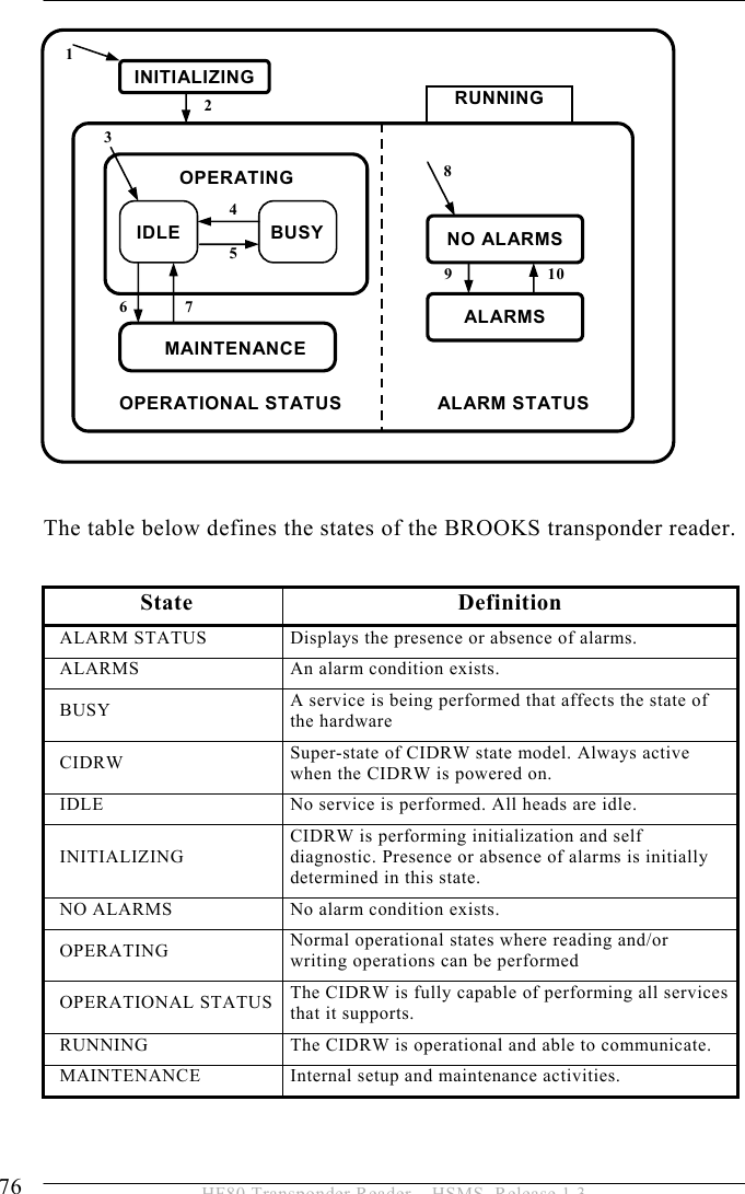
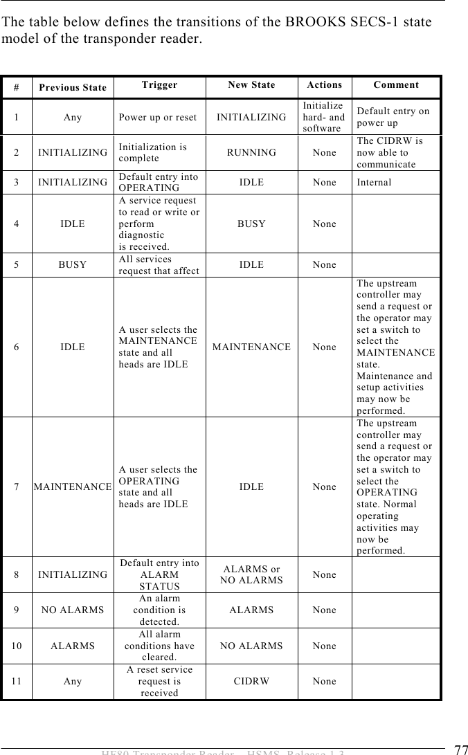
Brooks Automation HF80 Inductive Tag Reader User Manual HF80 HSMS A5 E 1 3
Brooks Automation (Germany) GmbH RFID Division Inductive Tag Reader HF80 HSMS A5 E 1 3
UserManual.wiki
>
Brooks Automation
>
HF80 User Manual
User Manual
Navigation menu
Upload a User Manual
Namespaces
Wiki Guide
HTML
PDF
Info
Views
User Manual
Discussion / Help
Navigation

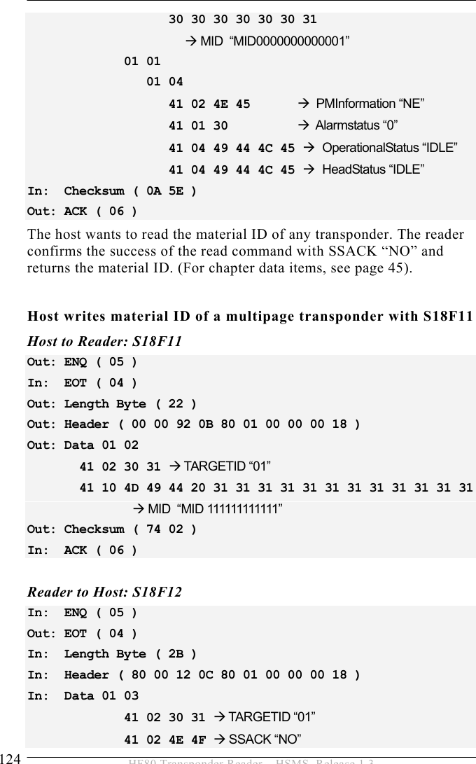
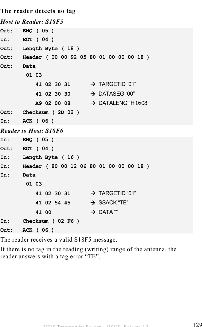
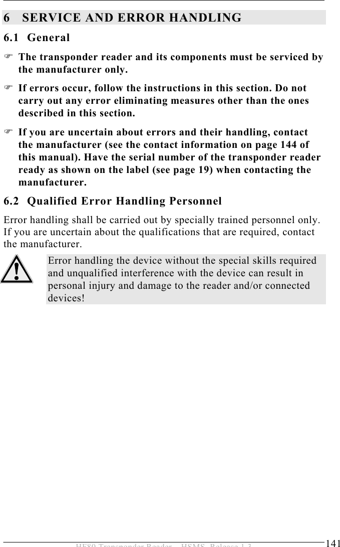
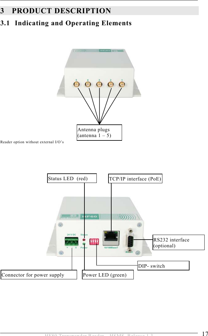
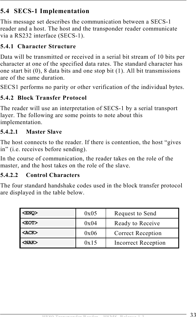
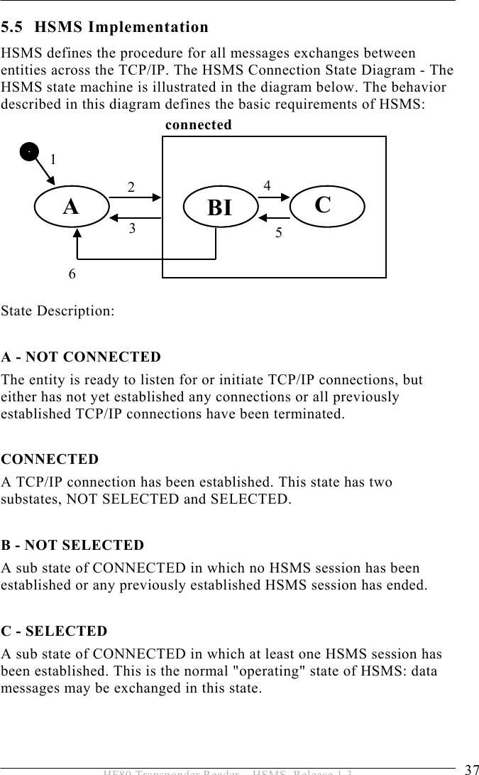
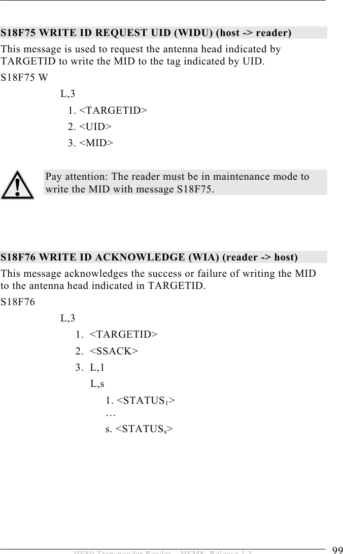
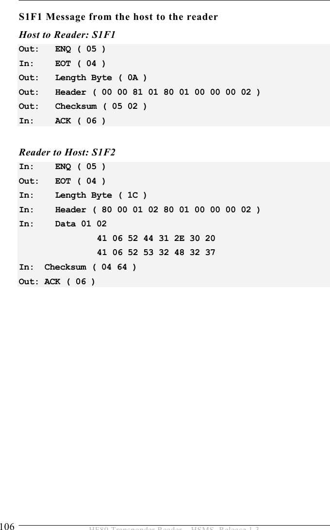
![1INTRODUCTION 6 HF80 Transponder Reader – HSMS, Release 1.3 1 INTRODUCTION 1.1 About this Device The BROOKS Transponder Reader System is a 13.56 MHz high-frequency identification system that uses FM transmission. The basic item is a transponder that works as a forgery-proof electronic identity disk. The reading unit of the system sends an energy impulse via the antenna. The capacitor of the passive, battery-free transponder is charged by this impulse. After that, the transponder returns a signal with the stored data. The reading process needs less than 3 ms (communication between tag and reader/antenna). As a sight connection between the transponder and the reader is not absolutely necessary, the transponder can also be identified through non-metallic material. The device communicates with the host via the TCP/IP interface with HSMS protocol. [Picture with serial and Ethernet interface]](https://usermanual.wiki/Brooks-Automation/HF80/User-Guide-1089115-Page-6.png)

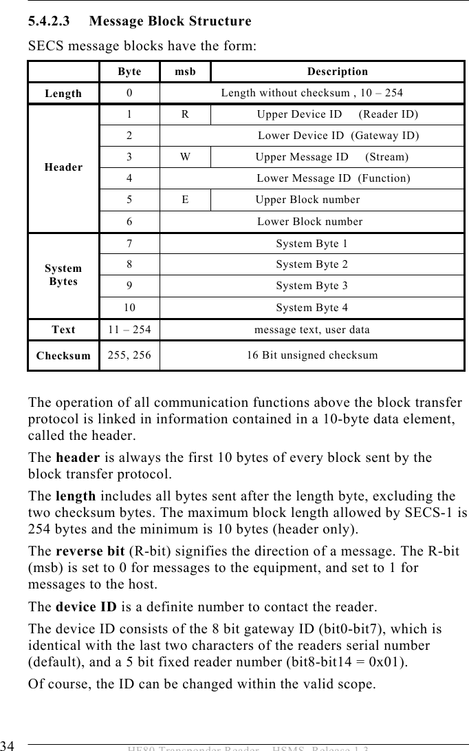
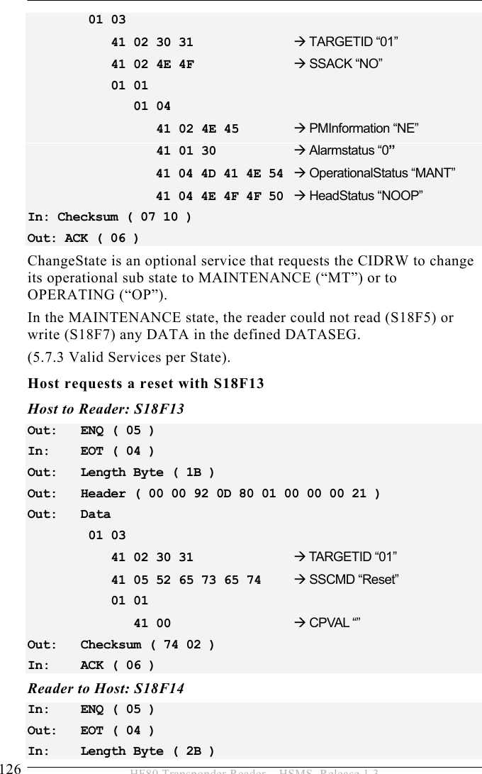
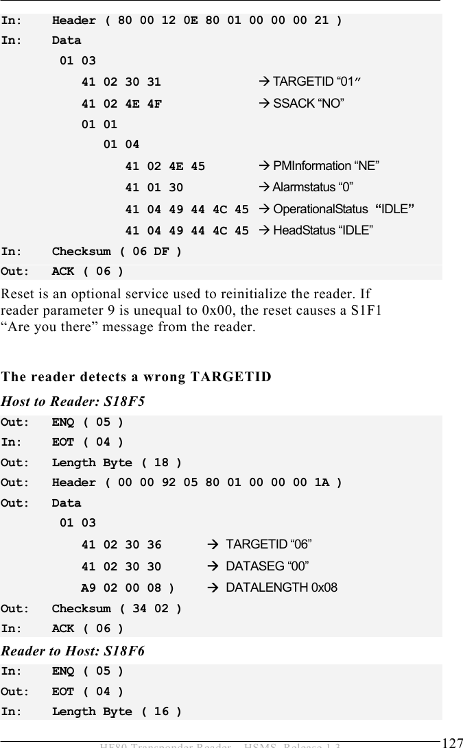
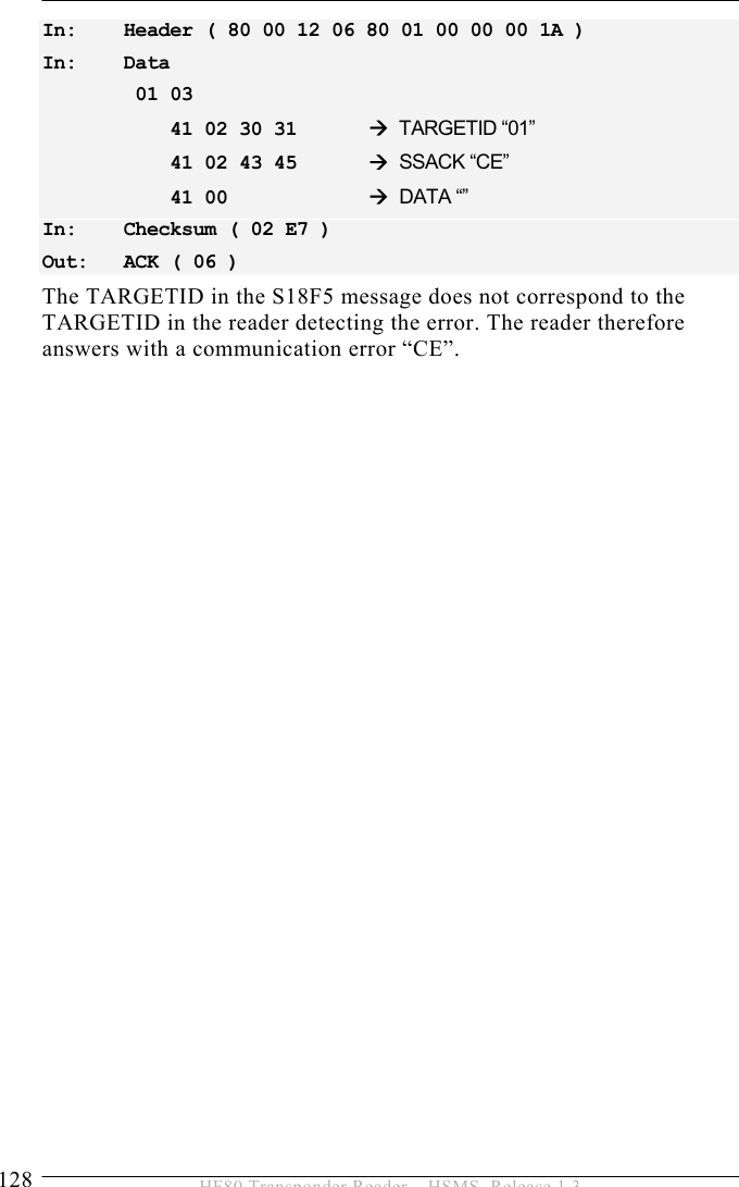
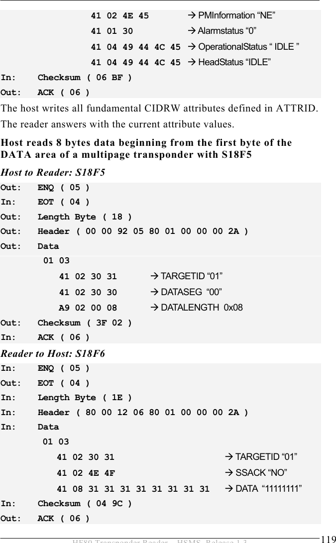
![OPERATION 5 45 HF80 Transponder Reader – HSMS, Release 1.3 A list is an ordered set of elements, where an element can be either an item or a list. The list header has the same form as an item header with format type 0. However, the length byte refers to the number of elements in the list rather than to the number of bytes. 5.6.2 Data Items The formats represent arrays of types: <type>[number of elements] where <type> is one of the following: Oct-CodeHex-Code Format Meaning Example 00 01 List List element with the number of the “Length” data elements <L2> <A “Hello”> <B 0x00> 11 25 Boolean 1 – Byte Boolean false = 00 ; true != 00 <Boolean1 0x00> 10 21 Binary Byte sequence of the length “Length” <B1 0x01> 20 41 ASCII Printable ASCII signs <A “Hello”> 31 65 I1 1 - Byte signed Integer <I1 123> 32 69 I2 2 - Byte signed Integer <I2 –12345> 34 71 I4 4 - Byte signed Integer <I4 2147483647> 30 61 I8 8 - Byte signed Integer <I8 931372980293834> 51 A5 U1 1 - Byte unsigned Integer <U1 0> 52 A9 U2 2 - Byte unsigned Integer <U2 #empty> 54 B1 U4 4 - Byte unsigned Integer <U4 429489725> 50 A1 U8 8 - Byte unsigned Integer <U8 763468676756767> 40 91 F8 8 - Byte floating point <F8 1.223 e204> 44 81 F4 4 - Byte floating point <F4 -1.23 >](https://usermanual.wiki/Brooks-Automation/HF80/User-Guide-1089115-Page-45.png)
![5 OPERATION 48 HF80 Transponder Reader – HSMS, Release 1.3 5.6.4 Data Items This section defines the data items used in the standard SECS-2 messages described in the section “Message Details”. Syntax: Name: A unique name for this data item. This name is used in the message definitions. Format: The permitted item format code which can be used for this standard data item. Item format codes are shown in hex and octal, as described in section data items (page 45). The notification “3()” indicates any of the signed integer formats (30, 31, 32, 34). Description: A description of the data item, with the meanings of specific values. Where used: The standard messages in which the data item appears. ALARM STATUS Format: A[1] Description: The value of the alarm status refers to the last reading process. If a read or write error occurs, the alarm status is set. A successful read or write resets the alarm status. When leaving maintenance mode, the alarm status is also deleted. 0 … No alarm 1 … Alarm Where used: STATUS](https://usermanual.wiki/Brooks-Automation/HF80/User-Guide-1089115-Page-48.png)
![OPERATION 5 49 HF80 Transponder Reader – HSMS, Release 1.3 ATTRID Format: A[max25] Description: Identifier for an attribute for a specific type of object. CIDRW Attribute Definitions: “Configuration”… Number of heads “AlarmStatus” Current CIDRW sub state of ALARM STATUS “OperationalStatus” Current CIDRW sub state of OPERATIONAL “SoftwareRevisionLevel” Revision (version) of software - 8 byte maximum “CarrierIDOffset” Offset of CID in CID field (MID area) “CarrierIDLength” Length of CID in CID field (MID area) “S1Status” Status of external I/O 01 (read only) “S2Status” Status of external I/O 02 (read only) “S3Status” Status of external I/O 03 (read only) “S4Status” Status of external I/O 04 (read only) “S5Status” Status of external I/O 05 (read only) “ECID_00” Æ parameter 0 – Gateway ID “ECID_01” Æ parameter 1 – Baudrate “ECID_02” Æ parameter 2 – Inter-Character-Timeout T1 “ECID_03” Æ parameter 3 – Block-Protocol-Timeout T2 “ECID_04” Æ parameter 4 – Reply-Timeout T3 “ECID_05” Æ parameter 5 – Inter-Block-Timeout T4 “ECID_06” Æ parameter 6 – Retry-Limit RTY “ECID_07” Æ parameter 7 – TARGETID high Byte “ECID_08” Æ parameter 8 – TARGETID low Byte “ECID_09” Æ parameter 9 – Heartbeat time “ECID_11” Æ parameter 11 – Reader ID “ECID_12” Æ parameter 12 – Acknowledgment Error Message “ECID_13” Æ parameter 13 – Communication Port “ECID_16” Æ parameter 16 – antenna power level “ECID_20” Æ parameter 20 – sensor activity “ECID_21” Æ parameter 21 – sensor 1 delay “ECID_22” Æ parameter 22 – sensor 2 delay “ECID_23” Æ parameter 23 – sensor 3 delay “ECID_24” Æ parameter 24 – sensor 4 delay](https://usermanual.wiki/Brooks-Automation/HF80/User-Guide-1089115-Page-49.png)
![OPERATION 5 51 HF80 Transponder Reader – HSMS, Release 1.3 ATTRVAL Format: A[max4] Description: Value of the specified attribute. CIDRW Attribute Definitions: “Configuration” Number of heads “05” “AlarmStatus” Current CIDRW sub state of ALARM STATUS “0” … NO “1” … ALARMS “OperationalStatus” Current CIDRW sub state of OPERATIONAL “IDLE” … reader in IDLE mode “BUSY” … reader is busy “MANT” … maintenance mode “SoftwareRevisionLevel” Revision (version) of Software – 8 byte maximum “S1Status” – “S5Status” “ON” – Sensor is occupied “OFF” – Sensor is unoccupied ECID_00 to ECID_99 see data item ECV parameter 0 to parameter 45 Head Attribute Definitions: “HeadStatus” The current state “IDLE” … reader in IDLE mode “BUSY” … reader is busy “NOOP”… not operating “HeadID” Head number 01-05 (2 digits) “01” … Antenna 1 … “05” … Antenna 5 Where used: S18F2, S18F3](https://usermanual.wiki/Brooks-Automation/HF80/User-Guide-1089115-Page-51.png)
![5 OPERATION 52 HF80 Transponder Reader – HSMS, Release 1.3 CPVAL Format: A[max2] Description: State request value “OP” … operating state “MT” … maintenance state Where used: S18F13 DATA Format: A [max 200] Description: A vector or string of unformatted data. It depends on the size of the MID area. Where used: S18F6, S18F7, S18F68, S18F69 DATAB Format: B [max 200] Description: Byte array of transponder data. It depends on the size of the MID area. Where used: S18F6, S18F7, S18F68, S18F69 DATALENGTH Format: U2 Description: Total bytes to be sent. The DATALENGTH corresponds to the quantity of bytes that should be read or written. Where used: S18F5, S18F7, S18F67, S18F69](https://usermanual.wiki/Brooks-Automation/HF80/User-Guide-1089115-Page-52.png)
![OPERATION 5 53 HF80 Transponder Reader – HSMS, Release 1.3 DATASEG Format:A[2] Description: Used to identify the data requested. The DATASEG corresponds to the page number (PAGEID) of the ISO 15693 transponder. “00”: First page of any type of transponder or first page of the DATA area. Where used: S18F5, S18F7, S18F67, S18F69 DATASEGB Format:B[1] Description: Used to identify the data requested. The DATASEG corresponds to the real byte of the ISO 15693 transponder. Empty First byte of DATA area (depends on MID settings). Where used: S18F5, S18F7, S18F67, S18F69 EAC Format: B[1] Acknowledge code for new reader constant 0 … Parameter was set successfully 1 … Parameter could not be set Where used: S2F16 ECID Format: U1 Parameter number of reader (see data item ECV) Where used: S2F13, S2F15](https://usermanual.wiki/Brooks-Automation/HF80/User-Guide-1089115-Page-53.png)

![OPERATION 5 67 HF80 Transponder Reader – HSMS, Release 1.3 Parameter 100: (0x64) DIP-Switch Enabled Defines which DIP switches are enabled and have influence to the behavior. Via bit 0 to bit 3 the individual DIP switches can be enabled or disabled. Attention! Have a look to parameter 13 and value of DIP switch 1 before changing this value! 0 – 0x0F default: 0x0F Parameter 123: (0x7B) Fineversion Can be used to request the fineversion of the firmware. MDLN Format: A[6] Equipment model number. Where used: S1F2 Parameter 99 = 0x07 Parameter# Value 32 – Tag type 0x07 37 – MID area 0x04 53 – Readmode Low 54 – Writemode High Parameter 99 = 0x85 Parameter# Value 32 – Tag type 0x85 37 – MID area 0x04 53 – Readmode Low 54 – Writemode Low](https://usermanual.wiki/Brooks-Automation/HF80/User-Guide-1089115-Page-67.png)
![5 OPERATION 68 HF80 Transponder Reader – HSMS, Release 1.3 MHEAD Format: B[10] SECS message block header associated with message block in error. Where used: S9F1, S9F3, S9F5, S9F7 MID Format: A Description: Material ID Depending on the type of transponder, it is possible to modify the length of the MID. MID length can be set from “0” (no MID) to “10” (MID occupies the first 10 pages (writeable)) See parameter 37. Where used: S18F10, S18F11, S18F74, S18F75 OFLACK Format: B[1] Acknowledge code for OFF-LINE request. 0 … OFF-LINE acknowledge (reader is offline) Where used: S1F16 ONLACK Format: B[1] Acknowledge code for ON-LINE request. 0 … ON-LINE accepted (reader is online) Where used: S1F18](https://usermanual.wiki/Brooks-Automation/HF80/User-Guide-1089115-Page-68.png)
![OPERATION 5 69 HF80 Transponder Reader – HSMS, Release 1.3 OUTPUT Format: A[2] Number of the output of the antenna head indicated by TARGETID. “01” … Output 1 “02” … Output 2 Where used: S18F77 PM Information Format: A[2] Description: Preventive maintenance information “NE” … Normal execution “MR” … Maintenance required Where used: STATUS RAC Format: B[1] Reset acknowledge code. 0 … Reset to be done 1 … Reset could not be done Where used: S2F20 RIC Format: B[1] Reset code. 1 … Power up reset 2 … Software reset (without reset of Ethernet component) Where used: S2F19](https://usermanual.wiki/Brooks-Automation/HF80/User-Guide-1089115-Page-69.png)
![5 OPERATION 70 HF80 Transponder Reader – HSMS, Release 1.3 SHEAD Format: B[10] Stored SECS message block header. Only the last message is stored, which must still be confirmed by the host! Where used: S9F9 SOFTREV Format: A[max 6] Software revision code. Where used: S1F2 SSACK Format: A[2] Description: Result information on the status of the request concerning the service request. “NO” … Normal operation Indicates the success of the requested action “EE” … Execute error Cannot read tag data . Cannot read ID sequence. But equipment is normal. “CE” … Communication error Syntax error of message or message format or value. “HE” … Hardware error ID reader/writer head fault, ID reader/writer head is powered off. “TE” … Tag error Where used: S18F2, S18F4, S18F6, S18F8, S18F10, S18F12, S18F14, S18F66, S18F68, S18F70, S18F72, S18F74, S18F76, S18F78, S18F80](https://usermanual.wiki/Brooks-Automation/HF80/User-Guide-1089115-Page-70.png)
![OPERATION 5 71 HF80 Transponder Reader – HSMS, Release 1.3 SSCMD Format: A[max18] Description: Indicates an action to be performed by the subsystem. Used to differentiate between the different subsystem commands indicated. “ChangeState” … Change state “GetStatus” … Get state “PerformDiagnostics” … Perform diagnostics “Reset” … Reset CIDRW Where used: S18F13 SSTATE Format: A[max 3] Description: Provides status information of the external I/O of a specific head. “ON” - Sensor is occupied “OFF” - Sensor is unoccupied Where used: S18F71 STATE Format: A[max 5] Description: State of the external outputs of a specific head. “ON” … Output is ON “OFF” … Output is OFF “FLASH” … Output is flashing “KEEP” … Output remains current state Where used: S18F77](https://usermanual.wiki/Brooks-Automation/HF80/User-Guide-1089115-Page-71.png)
![5 OPERATION 72 HF80 Transponder Reader – HSMS, Release 1.3 STATUS Format: A[2] Description: Provides status information of a subsystem component. Consists of PM Information and the current values of the CIDRW attributes AlarmStatus, OperationalStatus, and HeadStatus. List of a Status L,4 <PMInformation> <AlarmStatus> <OperationalStatus> <HeadStatus> For data items OperationalStatus and HeadStatus see data item ATTRVAL. Where used: S18F2, S18F4, S18F8, S18F10, S18F12, S18F14, S18F70, S18F74, S18F76, S18F78, S18F80](https://usermanual.wiki/Brooks-Automation/HF80/User-Guide-1089115-Page-72.png)
![OPERATION 5 73 HF80 Transponder Reader – HSMS, Release 1.3 TARGETID Format: A[max10] Description: Identifies where a request for action or data is to be applied. The TARGETID corresponds to the last four characters of the serial number on a label on top of the reader. The reader uses the 2 digit HeadID as TARGETID to address the right antenna connector. See also reader parameter definitions (data item ECV) parameter 7 and 8. Example : “H8-xxxx-TS” (xxxx … dependent on the individual reader) The 4 ASCII character TARGETID xxxx is set by delivery (is used as serial number). The predefined TARGETID is fixed and cannot be changed. The 2 ASCII character HeadID corresponds to the antenna connectors 01 - 05. Where used: all stream 18 messages UID Format: B[8-12] Description: Unified identifier of the tag. In case of ISO15693 the UID has a length of 8 Bytes. Where used: S18F66, S18F67, S18F69, S18F73, S18F75](https://usermanual.wiki/Brooks-Automation/HF80/User-Guide-1089115-Page-73.png)
![5 OPERATION 74 HF80 Transponder Reader – HSMS, Release 1.3 Write Counter Format: B[4] Description: Write Counter. Part of Tag data which counts the number of write actions to this specific tag. Where used: S18F88, S18F90 Write Counter Length Format: U1 Description: Length of write counter data on tag. Where used: S18F87, S18F89](https://usermanual.wiki/Brooks-Automation/HF80/User-Guide-1089115-Page-74.png)
![5 OPERATION 78 HF80 Transponder Reader – HSMS, Release 1.3 5.7.3 Valid Services per State The following table shows which of the various services can be performed by the reader when the reader is in various individual states. Service Write ID Write Data Set Attributes Reset Read ID Read Data Perform Diag. Get Status Get Attributes Change State Reader State INIT IDLE/BUSY X X X X X X X X X MANT X X X X X X X X ) Note that when in the initializing state after power up or the reset service, the CIDRW may not be able to communicate. 5.8 Message Details 5.8.1 Equipment status S1F0: ABORT TRANSACTION (reader <-> host) Used instead of an expected reply to abort a transaction. Function 0 is defined in every stream and has the same meaning in every stream. S1F0 W . * Header Only S1F1: ARE YOU THERE REQUEST (reader <-> host, reply) Establishes if the gateway/reader or host is online. S1F1 W . * Header Only S1F2: ON-LINE DATA (host -> reader) The host signifies that it is online. S1F2 <L[2] <MDLN > <SOFTREV > >.](https://usermanual.wiki/Brooks-Automation/HF80/User-Guide-1089115-Page-78.png)
![OPERATION 5 79 HF80 Transponder Reader – HSMS, Release 1.3 S1F2: ON-LINE (reader -> host) The reader signifies that it is online. S1F2 <L[2] <MDLN > <SOFTREV > >. S1F15: REQUEST OFF_LINE (host ->reader, reply) The reader is requested to change the communication state to offline. The reader can only be set online again by using message S1F17 (or reset S2F19), all other messages will be aborted by the SxF0 message! S1F15 W. *Header Only S1F16: OFFLINE ACKNOWLEDGE (reader -> host) Acknowledge. S1F16 <OFLACK>. S1F17: REQUEST ON_LINE (host ->reader, reply) The reader is requested to change the communication state to online. S1F17 W. *Header Only S1F18: ONLINE ACKNOWLEDGE (reader -> host) Acknowledge. S1F18 <ONLACK>.](https://usermanual.wiki/Brooks-Automation/HF80/User-Guide-1089115-Page-79.png)
![5 OPERATION 80 HF80 Transponder Reader – HSMS, Release 1.3 5.8.2 Equipment Control S2F0: ABORT TRANSACTION (reader <-> host) Used instead of an expected reply to abort a transaction. Function 0 is defined in every stream and has the same meaning in every stream. S2F0 W . * Header Only S2F13: EQUIPMENT CONSTANT REQUEST (host-> reader, reply) The host requests one constant from the reader. S2F13 W <L[1] <ECID> >. S2F14: EQUIPMENT CONSTANT DATA (reader -> host) The reader sends the requested constant to the host. S2F14 <L[1] <ECV> >. S2F15: NEW EQUIPMENT CONSTANT SEND (host-> reader, reply) The host changes one reader constant. S2F15 W <L[1] <L[2] <ECID> <ECV> > >.](https://usermanual.wiki/Brooks-Automation/HF80/User-Guide-1089115-Page-80.png)

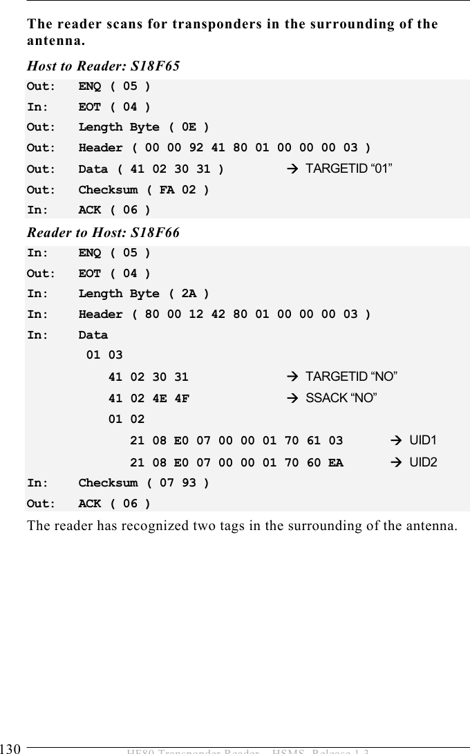
![5 OPERATION 102 HF80 Transponder Reader – HSMS, Release 1.3 S18F85: SCAN UID AND READ ID REQUEST (STR) (host -> reader, reply) This message is used to request the subsystem indicated in TARGETID to perform a scan and the read of the MID. S18F85 W <TARGETID> S18F86: SCAN UID AND READ ID ACKNOWLEDGE (STA) (reader -> host) This message reports the result from the subsystem specified in TARGETID for the requested action. S18F86 L,3 1. <TARGETID> 2. <SSACK> 3. L,s <L[2] <UID1> <MID1> <L[2] <UIDs> <MIDs> If the TARGETID is unknown, a communication error (CE) occurs. The action returns a UID and MID list of all ISO-tags found in the reading range. The list is restricted to 7 tags. If there are more than 7 tags within the antenna field the first 7 tags will be displayed only! For versions smaller than RS2P16 the list of tags is restricted to 3 tags.](https://usermanual.wiki/Brooks-Automation/HF80/User-Guide-1089115-Page-102.png)
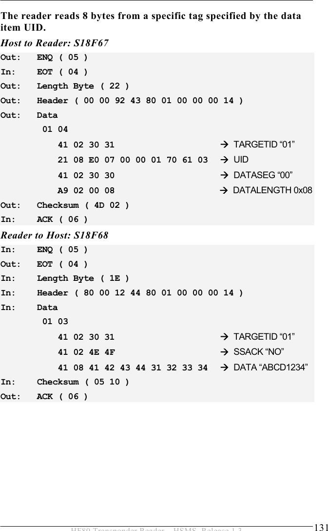
![OPERATION 5 103 HF80 Transponder Reader – HSMS, Release 1.3 S18F87: Read Write-Counter (host -> reader, reply) This message is used to request the subsystem indicated in TARGETID to read out the write counter of the tag. <S18F87 W <L2 <TARGETID> <Write Counter Length> > > S18F88: Read Write-Counter Response (reader -> host) This message reports the result from the subsystem specified in TARGETID for the requested action. <S18F88 <L[3/1] <TARGETID> <SSACK> <Write Counter> > >](https://usermanual.wiki/Brooks-Automation/HF80/User-Guide-1089115-Page-103.png)

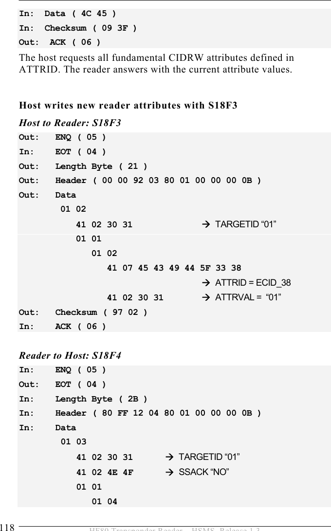
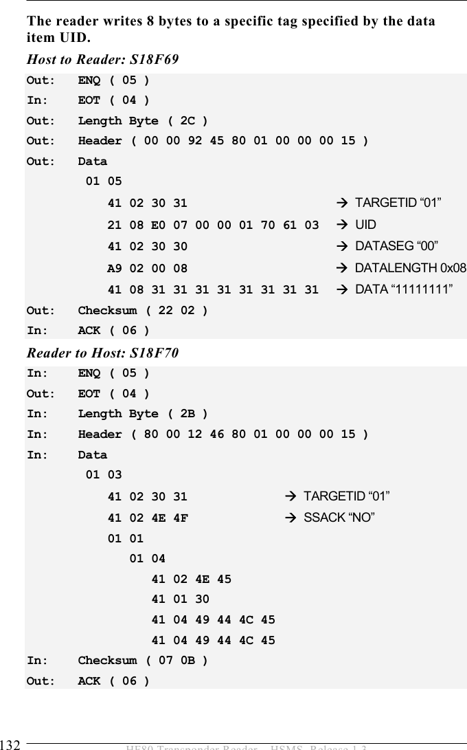
![OPERATION 5 123 HF80 Transponder Reader – HSMS, Release 1.3 S18F7 Write Data: DATASEG=<56> and DATALENGTH=<4> and DATA[4] < L4 < A TARGETID = '01' > < U2 DATASEGB = 56 > < U2 DATALENGTH = 4 > < B DATA = 44 45 46 47 > > S18F8 (WDA) - write data ACK < L3 < A TARGETID = '01' > < A SSACK = 'NO' > < L4 - STATUS1 < PMInformation < A = 'NE' > < A = '0' > < A = 'IDLE' > < A = 'IDLE' > > > Host reads material ID of a multipage transponder with S18F9 Host to Reader: S18F9 Out: ENQ ( 05 ) In: EOT ( 04 ) Out: Length Byte ( 0E ) Out: Header ( 00 00 92 09 80 01 00 00 00 17 ) Out: Data 41 02 30 31 Æ TARGETID “01” Out: Checksum ( D7 02 ) In: ACK ( 06 ) Reader to Host: S18F10 In: ENQ ( 05 ) Out: EOT ( 04 ) In: Length Byte ( 3D ) In: Header ( 80 00 12 0A 80 01 00 00 00 17 ) In: Data 01 04 41 02 30 31 Æ TARGETID “01” 41 02 4E 4F Æ SSACK “NO” 41 10 4D 49 44 20 30 30 30 30 30](https://usermanual.wiki/Brooks-Automation/HF80/User-Guide-1089115-Page-123.png)