Brooks Automation HF80 Inductive Tag Reader User Manual HF80 HSMS A5 E 1 3
Brooks Automation (Germany) GmbH RFID Division Inductive Tag Reader HF80 HSMS A5 E 1 3
User Manual

User Manual
HF80 Transponder Reader
(
Ethernet
–
HSMS
)

2 HF80 Transponder Reader – HSMS, Release 1.3
ID090014
Rev 03-2009
Printed in Germany
Subject to modifications
© 2009 BROOKS Automation (Germany) GmbH
RFID Division
Gartenstrasse 19
D-95490 Mistelgau
Germany
Tel: +49 9279 991 910
Fax: +49 9279 991 900
E-mail: rfid.support@brooks.com

3
HF80 Transponder Reader – HSMS, Release 1.3
TABLE OF CONTENTS
1 INTRODUCTION 6
1.1 About this Device ..................................................................6
1.2 About this Manual .................................................................7
2 SAFETY INSTRUCTIONS 8
2.1 Symbols and Types Used in this Manual ................................9
2.2 General Safety Instructions..................................................10
2.3 ESD Instructions..................................................................11
2.4 Proper Use...........................................................................12
2.5 Qualified Personnel .............................................................12
2.6 Declaration of Conformity ...................................................13
2.6.1 USA – Federal Communications Commission (FCC) .....13
2.6.2 Europe – CE Conformity ...............................................14
3 PRODUCT DESCRIPTION 17
3.1 Indicating and Operating Elements.......................................17
3.2 Description of Components..................................................18
3.3 Labeling Information ...........................................................19
3.4 Technical Data.....................................................................19
3.4.1 Transponder Reader ......................................................19
3.4.2 Power Supply and Current Input....................................20
3.5 Contents of Delivery............................................................20
3.6 Warranty and Liability.........................................................20
4 INSTALLATION 21
4.1 Installation Environment......................................................21
4.2 Qualified Installation Personnel ...........................................22
4.3 Unpacking ...........................................................................22
4.3.1 Disposal of Packing Material.........................................22
4.4 Mounting the Transponder Reader .......................................22
4.4.1 Dimensions for Planning ...............................................23
4.5 Installing the Antenna..........................................................24
4.5.1 Positioning....................................................................24
4.5.2 Available Antenna Types...............................................24
4.6 Connecting the Transponder Reader.....................................25
4.6.1 Antenna ........................................................................25
4.7 Power Connection................................................................25
4.8 Terminal Connection ...........................................................26
4.9 External Input and Output (optional)....................................26
4.10 DIP-Switches.......................................................................27
4.11 Starting Up ..........................................................................28
4.11.1 Required Operating Conditions......................................28

4 HF80 Transponder Reader – HSMS, Release 1.3
4.11.2 Parameter of Serial Interface .........................................28
4.11.3 Parameter of Ethernet Interface .....................................29
5 OPERATION 31
5.1 Operating Personnel.............................................................31
5.2 Introduction.........................................................................31
5.3 Modes..................................................................................32
5.4 SECS-1 Implementation.......................................................33
5.4.1 Character Structure........................................................33
5.4.2 Block Transfer Protocol.................................................33
5.5 HSMS Implementation.........................................................37
5.5.1 HSMS Message Exchange Procedures ...........................39
5.5.2 HSMS Message Format .................................................41
5.5.3 HSMS Message Header .................................................41
5.5.4 HSMS Message Format Summary..................................43
5.6 SECS-2 Implementation.......................................................44
5.6.1 Introduction...................................................................44
5.6.2 Data Items.....................................................................45
5.6.3 Message set...................................................................46
5.6.4 Data Items.....................................................................48
5.7 SEMI E99............................................................................75
5.7.1 Introduction...................................................................75
5.7.2 State Models .................................................................75
5.7.3 Valid Services per State.................................................78
5.8 Message Details...................................................................78
5.8.1 Equipment status ...........................................................78
5.8.2 Equipment Control ........................................................80
5.8.3 System Errors................................................................82
5.8.4 Subsystem Control and Data..........................................83
5.9 SECS-1 MESSAGE EXAMPLES.......................................105
5.10 HSMS MESSAGE EXAMPLES.........................................140
6 SERVICE AND ERROR HANDLING 141
6.1 General..............................................................................141
6.2 Qualified Error Handling Personnel ...................................141
6.3 Safety Instructions .............................................................142
6.4 Errors Indicated by the LEDs.............................................142
6.4.1 Power LED Not Illuminated ........................................142
6.5 Reader Does Not Respond..................................................143
6.6 Reset .................................................................................143
6.7 Power Cut..........................................................................144
6.8 Software Releases..............................................................144
6.9 Customer Service...............................................................144
7 DEINSTALLATION AND STORAGE 145
7.1 Deinstallation ....................................................................145

5
HF80 Transponder Reader – HSMS, Release 1.3
7.2 Storage ..............................................................................145
8 TRANSPORTATION AND DISPOSAL 146
8.1 Transportation ...................................................................146
8.2 Disposal ............................................................................146
9 ACCESSORIES 147
9.1 Device Options ..................................................................147
9.2 Antennas ...........................................................................148
9.2.1 Reading and Writing Ranges .......................................148
9.3 Power Supply ....................................................................148

1INTRODUCTION
6 HF80 Transponder Reader – HSMS, Release 1.3
1 INTRODUCTION
1.1 About this Device
The BROOKS Transponder Reader System is a 13.56 MHz high-
frequency identification system that uses FM transmission.
The basic item is a transponder that works as a forgery-proof electronic
identity disk.
The reading unit of the system sends an energy impulse via the
antenna. The capacitor of the passive, battery-free transponder is
charged by this impulse. After that, the transponder returns a signal
with the stored data.
The reading process needs less than 3 ms (communication between tag
and reader/antenna).
As a sight connection between the transponder and the reader is not
absolutely necessary, the transponder can also be identified through
non-metallic material.
The device communicates with the host via the TCP/IP interface with
HSMS protocol.
[Picture with serial and Ethernet interface]

INTRODUCTION 1
7
HF80 Transponder Reader – HSMS, Release 1.3
1.2 About this Manual
This manual contains information about installing, operating and error
handling the BROOKS HF80 Transponder Reader RS232/Ethernet. It
consists of nine chapters:
Introduction
Safety Instructions
Product Description
Installation
Operation
Service and Error Handling
Deinstallation and Storage
Transportation and Disposal
Accessories

2 SAFETY INSTRUCTIONS
8 HF80 Transponder Reader – HSMS, Release 1.3
2 SAFETY INSTRUCTIONS
This product is manufactured in accordance with state of the art
technology and corresponds to recognized safety regulations.
Nevertheless, there are dangers associated with the use of the
equipment even for its intended purpose. You should therefore read the
following safety information carefully and keep it in mind.
Only install and operate this equipment if it is in perfect condition and
with reference to this manual. Do not use the equipment if it is
damaged.
SAFETY INSTRUCTIONS 2
9
HF80 Transponder Reader – HSMS, Release 1.3
2.1 Symbols and Types Used in this Manual
This symbol alerts you to dangerous voltage
This symbol alerts you to important instructions
This symbol indicates electromagnetic radiation
This symbol alerts you to risk of explosion
This symbol alerts you to risk of fire
) This symbol indicates important additional
information
Electrostatically sensitive components
13:44:33
Incoming:
ENQ (05)
This type represents transmitted data display

2 SAFETY INSTRUCTIONS
10 HF80 Transponder Reader – HSMS, Release 1.3
2.2 General Safety Instructions
1 Read and understand all safety and operating instructions
before installing and operating the device.
2 This instruction is designed for specially trained personnel.
This device is NOT intended for use by the “general
population” in an uncontrolled environment. Installation,
operation and error handling the device shall be carried out by
specially trained personnel only (see additional information
on pages 12, 22, 31, and 141).
3 Keep these instructions. Store this manual in a place that can
be accessed at any time by all persons involved in installing,
operating and error handling the device.
4 Heed all warnings. Follow all warnings on and inside the
device and operating instructions.
5 Install in accordance with the manufacturer's instructions
only.
6 Only use attachments, accessories and connecting cables
supplied by the manufacturer.
7 All error handling other than the error handling listed in
chapter 6 of this manual must be carried out by the
manufacturer.
8 People with hearing aids should remember that radio signals
transmitted by the device might cause a very unpleasant
buzzing noise in their hearing aids.
9 Do not connect the device to any kind of power supply such
as a standard household power supply. The device should be
connected to a power supply of the type described in these
instructions only.
10 When you disconnect a cable, pull on its conductor and not on
the cable itself. Keep the connector evenly aligned to avoid
bending any connector pins. When you connect a cable,
ensure that the connector pins are positioned correctly.
11 Never over bend the antenna cable or expose it to mechanical
loads.
12 When replacement parts are required, use the replacement
parts specified by the manufacturer only. Unauthorized
substitutions may result in fire, electric shock, or other
hazards.
SAFETY INSTRUCTIONS 2
11
HF80 Transponder Reader – HSMS, Release 1.3
2.3 ESD Instructions
Static electricity can harm electronic components inside the
device. All persons who install or maintain the device must
be trained in ESD protection. ESD protection measures must
be observed when opening the device.
) Before removing or inserting components, disconnect the power
supply.
) To prevent electrostatic damage, static electricity must be
discharged from the body and tools before touching components
inside the device.
) Touch electro sensitive components carefully at their edges
only.
All antenna resonant circuit components carry
high voltage!
The installer is responsible for installing the
device to comply with FCC requirements of
human exposure to radio frequency.
To prevent fire, shock hazard, or annoying
interference, use recommended accessories only.
Remove the housing lid carefully to prevent
damage! Do not operate the device when the
housing lid is removed!
Do NOT operate this device without a proper
antenna attached. Proper antennas are antennas
supplied by the manufacturer and listed in section
„Accessories“.
Never locate the antenna so that it is very close to
or touching parts of the body while transmitting.
2 SAFETY INSTRUCTIONS
12 HF80 Transponder Reader – HSMS, Release 1.3
2.4 Proper Use
This product was developed for reading and writing transponders only.
Any other use of this device would constitute abuse and would render
the user’s authority to install and operate the device invalid.
This product is designed to be mounted and operated in an industrial
environment as a built-in-device only. It is not designed to be used as a
stand-alone or a portable device or in a non-industrial environment,
such as a household, vehicle or open-air environment.
2.5 Qualified Personnel
This manual is designed for specially trained personnel only. This
device must be installed and maintained by the manufacturer or its
specially trained representatives.
Intervention or error handling not expressively approved in this manual
must be carried out by the manufacturer’s personnel only. If you are
unsure about the qualifications that are actually required, contact the
manufacturer.
Unqualified interventions may result in personal injury or
damage to the device!

SAFETY INSTRUCTIONS 2
13
HF80 Transponder Reader – HSMS, Release 1.3
2.6 Declaration of Conformity
2.6.1 USA – Federal Communications Commission (FCC)
This device complies with Part 15 of the FCC Rules. Operation is
subject to the following two conditions:
1) This device may not cause harmful interference and
2) This device must accept any interference received, including
interference that may cause undesired operation.
NOTE: This equipment has been tested and found to comply with the limits
for a Class A digital device, pursuant to Part 15 of the FCC Rules.
These limits are designed to provide reasonable protection against harmful
interference when the equipment is operated in a commercial environment.
This equipment generates, uses, and can radiate radio frequency energy and,
if not installed and used in accordance with the instruction manual, may cause
harmful interference to radio communications. Operation of this equipment in
a residential area is likely to cause harmful interference in which case the
user will be required to correct the interference at his own expense.
FCC ID N5GHF80
Changes or modifications not expressly approved by the
party responsible for compliance may void the user’s
authority to operate the equipment.

2 SAFETY INSTRUCTIONS
14 HF80 Transponder Reader – HSMS, Release 1.3
2.6.2 Europe – CE Conformity
Konformitätserklärung gemäß dem Gesetz über Funkanlagen und
Telekommunikationsendeinrichtungen (FTEG) und der Richtlinie
1999/5/EG (R&TTE)
Declaration of Conformity in accordance with the Radio and
Telecommunications Terminal Equipment Act (FTEG) and Directive
1999/5/FC (R&TTE Directive)
Hersteller / Verantwortliche Person
Manufacturer / responsible person
BROOKS Automation
(Germany) GmbH /
Herr Dittrich
erklärt, dass das Produkt
declares that the product
HF80
Type (ggf. Anlagenkonfiguration mit
Angabe der Module):
Type (if applicable, configuration
including the modules)
5 Telekommunikations(Tk-)end-
einrichtung
Telecommunications terminal
equipment
Funkanlage
Radio equipment
Verwendungszweck
lntended purpose
Identification system
Geräteklasse / Equipment class 2
bei bestimmungsgemäßer Verwendung den grundlegenden
Anforderungen des § 3 und den übrigen einschlägigen
Bestimmungen des FTEG (Artikel 3 der R&TTE) entspricht.
complies with the essential requirements of §3 and the other relevant
provisions of the FTEG
(Article 3 of the R&TTE Directive), when used for its intended
purpose.

SAFETY INSTRUCTIONS 2
15
HF80 Transponder Reader – HSMS, Release 1.3
Gesundheit und Sicherheit gemäß § 3 (1) 1. (Artikel 3 (1) a))
Health and safety requirements pursuant to
§ 3 (1) 1. (Article 3(1) a))
angewendete harmonisierte Normen
Harmonized standards applied
EN 60950
Schutzanforderungen in Bezug auf die elektromagnetische
Verträglichkeit (§ 3 (1) 2, Artikel 3 (1) b)
Protection requirements concerning electromagnetic compatibility §
3(1)(2), (Article 3(1)(b))
angewendete harmonisierte Normen
Harmonized standards applied
EN 301 489-3 (2002-08)
EN 301 489-1 (2005-09)
Einhaltung der grundlegenden
Anforderungen auf andere Art und
Weise (hierzu verwendete Standards /
Spezifikationen)
Other means of proving conformity
with the essential requirements
(standards/specifications used)
Maßnahmen zur effizienten Nutzung des
Funkfrequenzspektrums
Measures for the efficient use of the radio frequency spectrum
Luftschnittstelle bei Funkanlagen gemäß § 3(2) (Artikel 3(2))
Air interface of the radio systems pursuant to § 3(2) (Article 3(2))
Angewendete harmonisierte Normen
Harmonized standards applied
Einhaltung der grundlegenden
Anforderungen auf andere Art und
Weise (hierzu verwendete Standards /
Schnittstellenbeschreibungen)
Other means of proving conformity
with the essential requirements
(standards/interface specifications
used)
EN 300 330-1 V1.3.1
EN 300 330-2 V1.3.1

2 SAFETY INSTRUCTIONS
16 HF80 Transponder Reader – HSMS, Release 1.3
BROOKS Automation (Germany)
GmbH
Gartenstr. 19
D-95490 Mistelgau
Germany
Phone +49 9279 991 910
Fax +49 9279 991 900
Mistelgau, 01.08.2008
Gerald Dittrich
(Place and date of issue) (Name and signature)
PRODUCT DESCRIPTION 3
17
HF80 Transponder Reader – HSMS, Release 1.3
3 PRODUCT DESCRIPTION
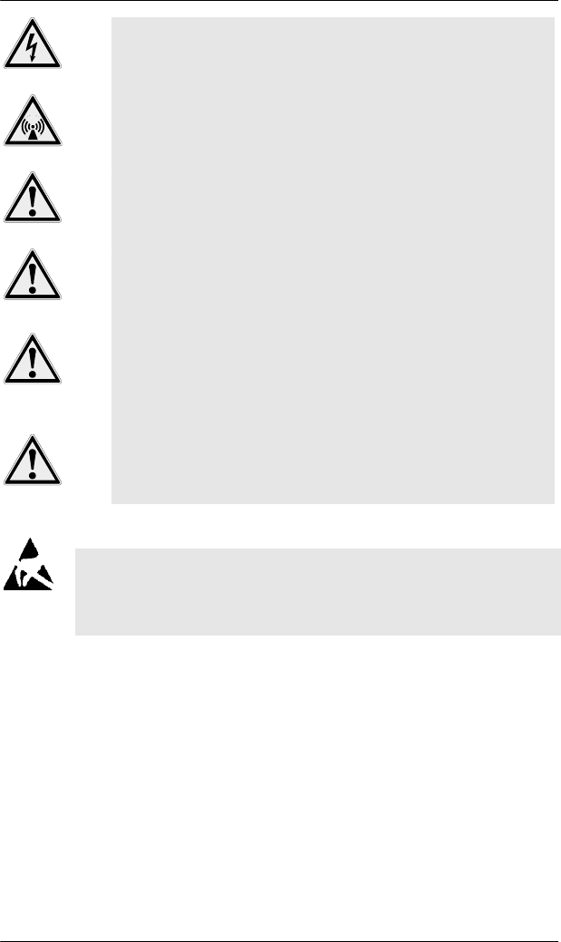
3.1 Indicating and Operating Elements
Reader option without external I/O’s
Power LED (green)
DIP- switch
RS232 interface
(optional)
Status LED (red)
Connector for power supply
TCP/IP interface (PoE)
Antenna plugs
(antenna 1 – 5)

3 PRODUCT DESCRIPTION
18 HF80 Transponder Reader – HSMS, Release 1.3
3.2 Description of Components
Power LED
If the device is connected to a power supply, the LED is illuminated
green and the reader is ready for use.
Status LED
The Status-LED is used as feedback for reading and writing action in
test mode and polling mode. If the reader is in test mode or polling
mode and the read action was successful the red LED is on. In case of
a reading error the LED is off.
RS232 interface (optional)
The device can communicate via the serial interface (9 pin Sub-D
female plug). Baud rates between 1200 Bd and 57600 Bd are possible.
Optional a 10/100BaseT interface is available.
Ethernet interface
The device can communicate via the 10/100 BaseT interface. Optional
a RS232 interface is available. The Device supports Power over
Ethernet (PoE).
DIP-Switches
The 4 DIP switches are used to set some parameters of the reader.
Connector power supply
Plug for the 24 VDC power supply.
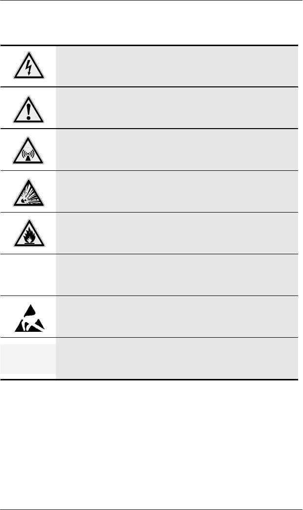
Antenna plugs 1 to 5:
The number of the antenna plugs corresponds to the HeadID of the
communication protocol.

PRODUCT DESCRIPTION 3
19
HF80 Transponder Reader – HSMS, Release 1.3
3.3 Labeling Information
3.4 Technical Data
3.4.1 Transponder Reader
Parameter Value
Operation temperature 0°C to +50°C
32°F to 122°F
Stock temperature -25°C to +70°C
-13°F to +158°F
Permissible humidity @ 50C° 25 - 80 %
Transmitter frequency 13.56 MHz
Max. transmitting level 1W
Output impedance 50Ω
Protection mode IP 40
Housing material PS
Weight (without/with IO-module) about 280g
Fuse type TR5 500mA (T)
Serial interface RS232 1200 Bd –
57600 Bd
Ethernet-Interface 10/100BaseT
Serial number
Part number

3 PRODUCT DESCRIPTION
20 HF80 Transponder Reader – HSMS, Release 1.3
3.4.2 Power Supply and Current Input
Description Min Type Max Unit
Voltage (proof against connecting
to the wrong terminal)
12 24 42 VDC
Current without presence sensor
(starting process excluded)
80 – 300 mA
Electrical Power: max. 7W
) Pay attention to the power consumption to ensure that your PoE
infrastructure has a sufficient power supply.
Take care that you connect only one type of power supply
to the reader at the same time. PoE (via Ethernet cable)
or external power supply, but not both together.
Otherwise the reader hardware or the external power
supply can be damaged.
3.5 Contents of Delivery
Number Description
1 HF80 Transponder Reader Ethernet/RS232
1 User manual (on CD-ROM)
1 Accompanying letter
) For available or required accessories, e.g. antennas, adapters
and cables, see section “Accessories” on page 147 in this
manual.
3.6 Warranty and Liability
The warranty period is 12 months and begins with the moment of
delivery of the device as proved by an invoice or other documents.
The warranty includes the repair of all damages to the device that
occur within the warranty period, and which are evidently caused by
faults of the material or production defects.
The warranty does not include damages caused by incorrect
connection, inappropriate handling and non-observance of the
technical reports.
INSTALLATION 4
21
HF80 Transponder Reader – HSMS, Release 1.3
4 INSTALLATION
4.1 Installation Environment
This device is designed for use in an indoor
industrial environment only. Installation is only
permitted in an environmental indoor climate with
a constant temperature of between 0°C and +50°C /
32°F and 122°F, humidity between 25% and 80%,
and a maximum temperature of +50°C / 122°F.
Do not install or use this device in or near water.
Never spill liquids of any kind onto the device.
Should spillage occur, unplug the device and have
it checked by a technician.
Do not install near heat sources such as radiators,
heat registers, stoves, or other apparatus (including
amplifiers) that produce heat. Do not install the
device in a flammable environment.
Never expose the device to intense changes in
temperature, otherwise condensation can develop
inside the device and cause damages.
Do not locate the device near overhead power lines
or other electric lights, or power circuits or where
it can encounter such circuits. When installing the
device, take extreme care not to encounter such
circuits as they can cause serious injury or death.
The device should not be used in the immediate
vicinity of electrical units (such as medical units,
monitors, telephones, televisions and energy-saver
lamps), magnetic data carriers, or metallic objects.
This could result in reduced reading/writing ranges.
Never use the device in potentially explosive areas
(such as paint shops).
Do not position the device in a location where it
can suffer from vibration or shock.
4 INSTALLATION
22 HF80 Transponder Reader – HSMS, Release 1.3
When the device is installed, the installation
location must be adequately illuminated.
Do not install the device during periods of
lightning.
Ensure the installation location complies with FCC
requirements for human exposure to radio
frequency.
) When determining the assembly location, consider
the length of the antenna cable that will be used,
and the reading and writing range. See section
„Accessories/Antennas“ for further information.
4.2 Qualified Installation Personnel
The installation shall be carried out by specially trained personnel
only. If you are uncertain about the qualification, contact the
manufacturer.
Operating the device without special skills can result in
damage to the reader and/or connected devices!
4.3 Unpacking
This device and its accessories were packed under clean room
conditions. To preserve these conditions, the device must be unpacked
under clean room conditions.
4.3.1 Disposal of Packing Material
The packing material consists of cardboard and film. Dispose of these
materials separately in accordance with the relevant legislation in your
country.
4.4 Mounting the Transponder Reader
) The mounting surface must be stable, non-flammable, dry and
clean. If necessary, clean it before installing the device.
INSTALLATION 4
23
HF80 Transponder Reader – HSMS, Release 1.3
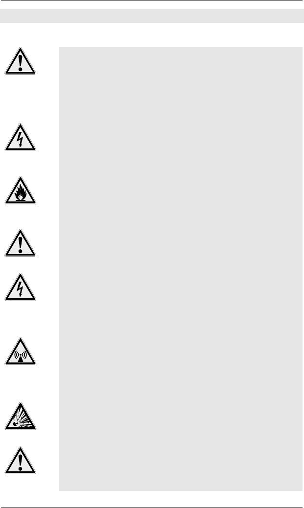
4.4.1 Dimensions for Planning
130 118
45
105
25
120
40
80
Space for plugs*
Space for plugs*
*Keep space free for plugs. Dimensions for
straight cable plugs.
6.5
4 INSTALLATION
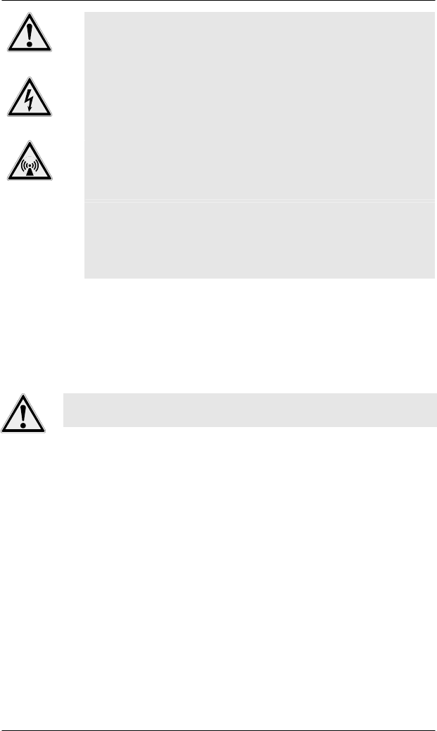
24 HF80 Transponder Reader – HSMS, Release 1.3
Drawing with external I/O’s
4.5 Installing the Antenna
) When installing the antenna, consider the required reading and
writing ranges. The reader can be used properly only if the
transponder is located within the individual reading/writing
range of the antenna!
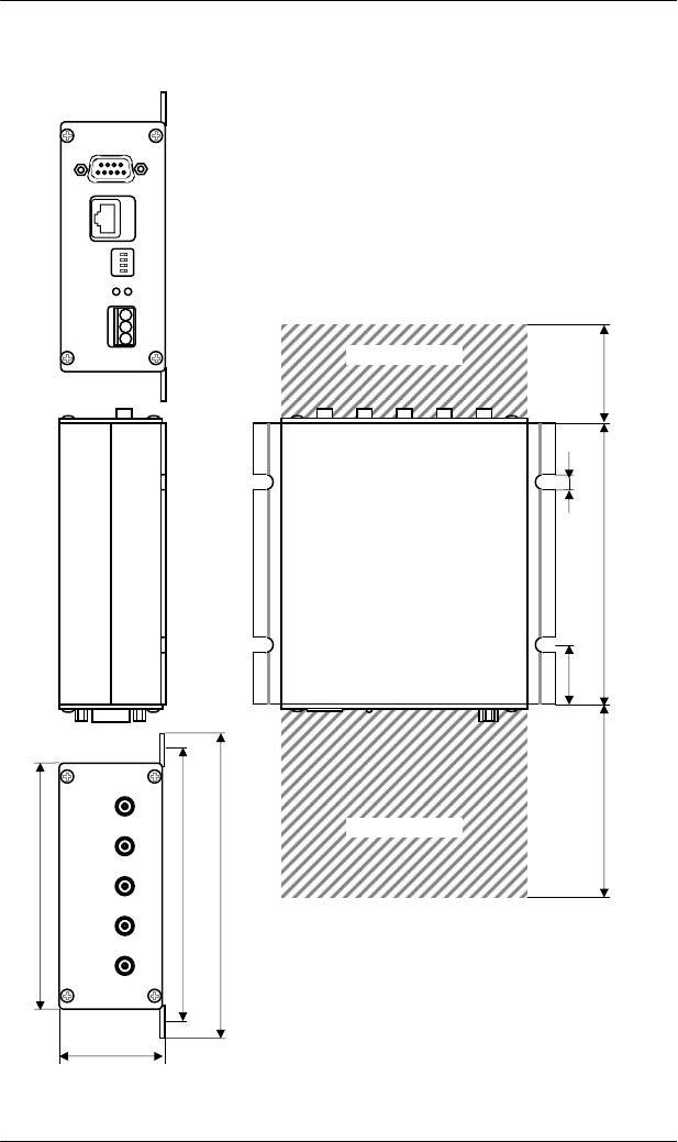
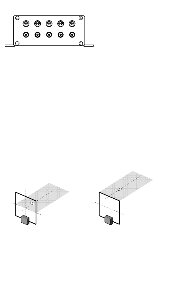
4.5.1 Positioning
Reliable reading and writing depends on the range and position of the
transponder to the antenna.
Optimal position of the transponder and antenna for different
orientations of the transponder.
4.5.2 Available Antenna Types
Different types of antennas are available on request.
INSTALLATION 4
25
HF80 Transponder Reader – HSMS, Release 1.3
4.6 Connecting the Transponder Reader
4.6.1 Antenna
Connect the antenna to the antenna plug (see illustration page 17).
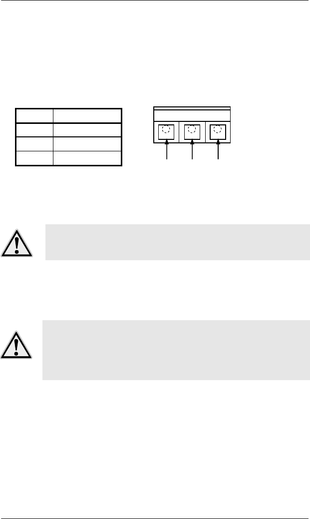
4.7 Power Connection
Built-in male plug, plastic (power supply)
PIN Signal
1 +24V
2 0V
3 Screen / PE
The device can be connected to an interior DC power circuit of the
equipment or to a DC adapter (see section “Accessories”, page 147).
Note the required voltage (see technical data, page 20). Use
cables, plugs and adapters provided by the manufacturer
only!
Once the device is connected to the power supply, the power LED is
illuminated (see illustration page 17). If it is not illuminated, see
section 6 for help.
Take care that you connect only one type of power supply
to the reader at the same time. PoE (via Ethernet cable)
or external power supply, but not both together.
Otherwise the reader hardware or the external power
supply can be damaged.
12
3
4 INSTALLATION
26 HF80 Transponder Reader – HSMS, Release 1.3
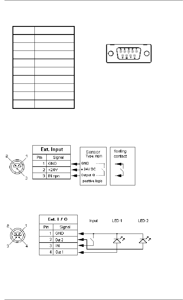
4.8 Terminal Connection
Built-in female plug (RS232 interface) - optional
The serial interface is a Sub-D female
plug (9 contacts); a serial connection line
(switched 1:1) can be used.
4.9 External Input and Output (optional)
There are two different versions available:
1. One input per antenna head.
2. One input and two outputs per antenna head.
PIN DB9
1
N
C
2 TxD
3 RxD
4
N
C
5 GND
6
N
C
7
N
C
8
N
C
9
N
C

INSTALLATION 4
27
HF80 Transponder Reader – HSMS, Release 1.3
4.10 DIP-Switches
The DIP switches can be used to change the behavior of some features
of the reader. Parameter 100 enables or disables the functionality of the
DIP-switches.
DIP-switch 1: Communication-Port
OFF: RS232
ON: Ethernet
DIP-switch 2: Test-Mode
OFF: Normal operation mode
ON: Test mode for antenna 1 enabled
DIP-switch 3: not used in this version
DIP-switch 4: Behavior for test mode / polling mode
Test mode:
OFF: Scan UID of all possible tag types
ON: Reading and writing of one page of a ISO15693 tag
Notes:
1. Only DIP-switch 1 is ON by default.
2. If the test mode is active, the test mode has priority.
3. The use of the DIP switches depends on the setting of parameter
‚DIP switches enabled’. All DIP switches are activated by default.

4 INSTALLATION
28 HF80 Transponder Reader – HSMS, Release 1.3
4.11 Starting Up
4.11.1 Required Operating Conditions
To operate the reader, the following requirements must be met:
) An antenna must be connected correctly to the reader.
) The power supply must be connected (except POE is used).
) The transponder must be located within the individual
reading/writing range of the antenna.
) Setting of the DIP switches is correct.
4.11.2 Parameter of Serial Interface
Baud rate 19200
Databits 8
Stopbit 1
Parity none
INSTALLATION 4
29
HF80 Transponder Reader – HSMS, Release 1.3
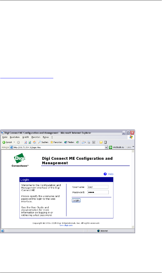
4.11.3 Parameter of Ethernet Interface
The connection to the Ethernet is realized by an independent Ethernet
component. There are small tools available to configure the Ethernet
component. Using a discovery tool all readers available in the network
can be found. A double click on the IP address in the list opens a
Webserver applet in a web browser window to configure the Ethernet
component. If the IP address of the reader is known a web browser can
be used to access the web server directly. The following pictures show
the login page of the web server.
http://xxx.xxx.xxx.xxx/
Username: "root"
Password: "dbps"
xxx.xxx.xxx.xxx – current IP address of the device
Login dialog:
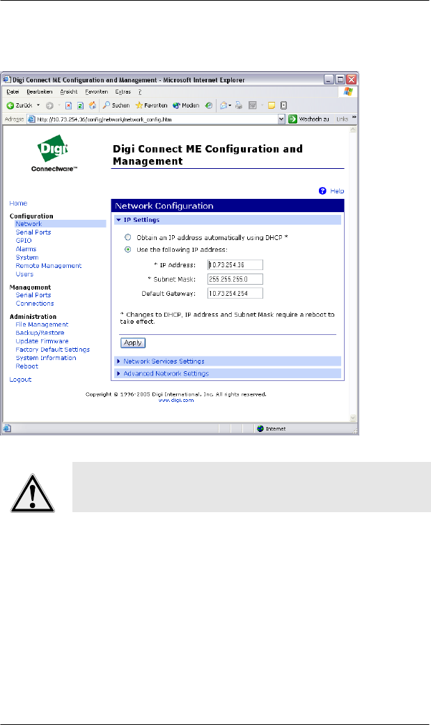
4 INSTALLATION
30 HF80 Transponder Reader – HSMS, Release 1.3
The link ‚Network’ opens the page to change the IP address. The
button ‘Apply’ confirms the change and starts a reboot of the device.
The TCP/IP port used by the HSMS protocol is set to
3241 by default. If you want to set another port please
contact the manufacturer.

OPERATION 5
31
HF80 Transponder Reader – HSMS, Release 1.3
5 OPERATION
5.1 Operating Personnel
The HF80 Transponder Reader is designed to be operated by
specially trained personnel only. If you have doubts about
the qualification required, contact the manufacturer.
Operating the device without special skills can result in
damage to the reader and/or connected devices!
5.2 Introduction
The SEMI Equipment Communications Standard E4 (SECS-1) defines
a communication interface that is suitable for exchanging messages
between semiconductor processing equipment and a host. A host is a
computer or network of computers that exchanges information with the
equipment to perform/execute the production.
The standard does not define the data contained within a message. The
meaning of messages must be determined through a message contents
standard such as SEMI Equipment Communications Standard E5
(SECS-2).
This standard provides the means for independent manufacturers to
produce equipment and hosts that can be connected without requiring
specific knowledge of each other.
The SECS-1 protocol can be seen as a layered protocol used for point-
to-point communication. The layers within SECS-1 are the physical
link, block transfer protocol and message protocol.
It is not intent of the standard to meet the communication needs of all
possible applications. For example, the speed of RS232 may be
insufficient to meet the needs of transferring mass amounts of data or
programs in a short period, such as may be required by high-speed
functional test applications.
In a network, the roles of host and equipment may be assumed by any
party in the network. In this situation, one end of the communications
link must assume the role of the equipment and the other the role of
the host.
High-speed SECS Message services (HSMS) is intended as an
alternative to SEMI E4 for applications where higher speed
communication is needed or when a simple point to point topology is
insufficient.
Electronic Industries Association Standards:
EIA RS-232-C Interface between Data Terminal Equipment and Data
Communication Equipment Employing Serial Binary Data Interchange.

5 OPERATION
32 HF80 Transponder Reader – HSMS, Release 1.3
5.3 Modes
The HF80 reader offers the possibility to work as SECS1 and HSMS
reader. You can easily change between the two modes by switching
one of the DIP- switches on the front panel of the reader.
The second possibility to switch the modes is changing reader
parameter 13. (communication port).
SECS1 uses the serial interface to establish the direction of
communication for passing message blocks. The SECS1 message set
describes the communication between the reader and a host.
If the reader uses the HSMS mode, it works as HSMS-server. That
means that it waits for a connection inquiry of any HOST-PC.
TCP/IP: IP-Address xxx.xxx.xxx.xxx Port 3241
If a connection inquiry of any HOST takes place, the reader initializes
the HSMS-connection, and the SECS II messages defined in the
message set are forwarded from the reader to the respective HOST and
vice versa.
It is possible to operate all readers connected to the network via one or
also via several HOST-PC’s.
But one HSMS reader can only be connected to one HOST at the same
time.

OPERATION 5
33
HF80 Transponder Reader – HSMS, Release 1.3
5.4 SECS-1 Implementation
This message set describes the communication between a SECS-1
reader and a host. The host and the transponder reader communicate
via a RS232 interface (SECS-1).
5.4.1 Character Structure
Data will be transmitted or received in a serial bit stream of 10 bits per
character at one of the specified data rates. The standard character has
one start bit (0), 8 data bits and one stop bit (1). All bit transmissions
are of the same duration.
SECS1 performs no parity or other verification of the individual bytes.
5.4.2 Block Transfer Protocol
The reader will use an interpretation of SECS-1 by a serial transport
layer. The following are some points to note about this
implementation.
5.4.2.1 Master Slave
The host connects to the reader. If there is contention, the host “gives
in” (i.e. receives before sending).
In the course of communication, the reader takes on the role of the
master, and the host takes on the role of the slave.
5.4.2.2 Control Characters
The four standard handshake codes used in the block transfer protocol
are displayed in the table below.
<ENQ> 0x05 Request to Send
<EOT> 0x04 Ready to Receive
<ACK> 0x06 Correct Reception
<NAK> 0x15 Incorrect Reception

5 OPERATION
34 HF80 Transponder Reader – HSMS, Release 1.3
5.4.2.3 Message Block Structure
SECS message blocks have the form:
Byte msb Description
Length 0 Length without checksum , 10 – 254
1 R Upper Device ID (Reader ID)
2 Lower Device ID (Gateway ID)
3 W Upper Message ID (Stream)
4 Lower Message ID (Function)
5 E Upper Block number
Header
6 Lower Block number
7 System Byte 1
8 System Byte 2
9 System Byte 3
System
Bytes
10 System Byte 4
Text 11 – 254 message text, user data
Checksum 255, 256 16 Bit unsigned checksum
The operation of all communication functions above the block transfer
protocol is linked in information contained in a 10-byte data element,
called the header.
The header is always the first 10 bytes of every block sent by the
block transfer protocol.
The length includes all bytes sent after the length byte, excluding the
two checksum bytes. The maximum block length allowed by SECS-1 is
254 bytes and the minimum is 10 bytes (header only).
The reverse bit (R-bit) signifies the direction of a message. The R-bit
(msb) is set to 0 for messages to the equipment, and set to 1 for
messages to the host.
The device ID is a definite number to contact the reader.
The device ID consists of the 8 bit gateway ID (bit0-bit7), which is
identical with the last two characters of the readers serial number
(default), and a 5 bit fixed reader number (bit8-bit14 = 0x01).
Of course, the ID can be changed within the valid scope.

OPERATION 5
35
HF80 Transponder Reader – HSMS, Release 1.3
Upper Device ID
Lower Device ID
Direction reader to host: 0x81xx *
Direction Host to equipment (BROOKS HF5x reader): 0x01xx *
* … the serial number is located on a label on the housing lid of each
reader
The W-Bit indicates that the sender of a primary message expects a
reply. A value of one in the W-bit means that a reply is expected.
The message ID identifies the format and content of the message being
sent.
A primary message is defined as any odd-numbered message.
A secondary message is defined as any even-numbered message.
The end bit determines whether a block is the last block of the
message. A value of 1 means that the block is the last block.
A message sent as more than one block is called a multi-block
message. A block number of one is given to the first block, and the
block number is incremented by one for each subsequent block until
the entire message is sent.
As all messages can be sent in one block, the block number always has
the value 1.
The system bytes in the header of each message for a given device ID
must meet the following requirements:
The system bytes of a primary message must be distinct from those
bytes of all currently open transactions initiated from the same end
of the communications link.
The system bytes of the reply message are required to be the same
as the system bytes of the corresponding primary message.
The system bytes are incremented for each primary message.
The checksum is calculated as the numeric sum of the unsigned binary
values of all the bytes, after the length byte and before the checksum in
a single block.
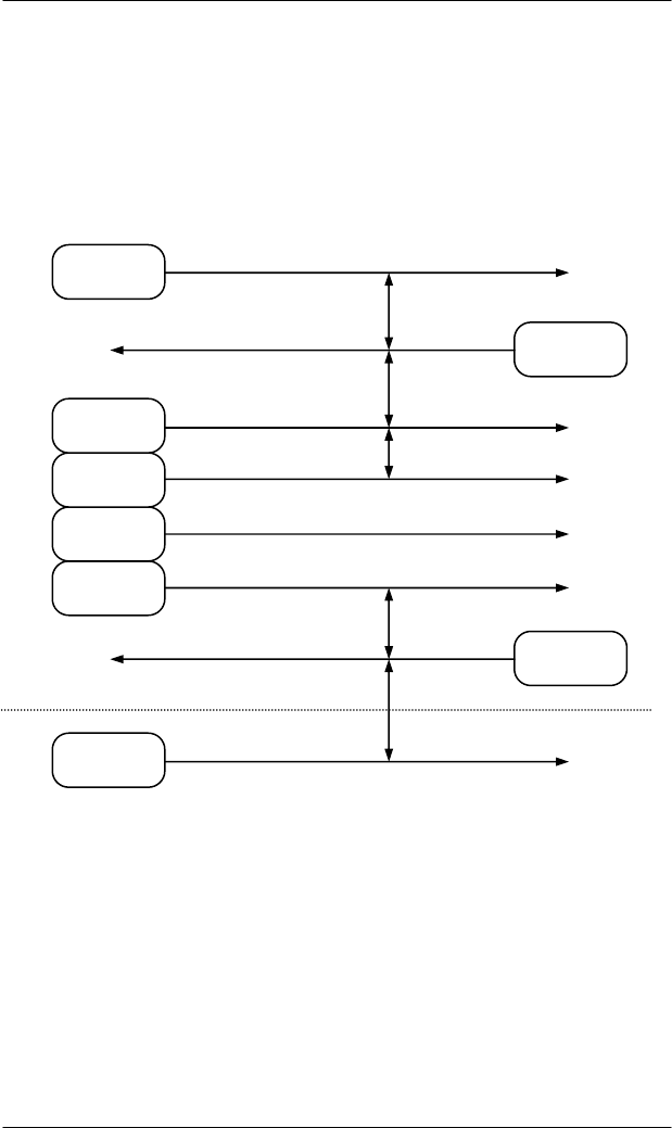
5.4.2.4 Block Transfer Protocol
The drawing below illustrates some simple message interactions
between the host and the equipment. The figure shows the handshake
sequence possible to acquire the status of the equipment.
serial number of the reader
R-Bit 0 0 0 0 0 0 1
5 OPERATION
36 HF80 Transponder Reader – HSMS, Release 1.3
When the host wants to send, it first sends an <ENQ> and then tries to
read.
If it receives an <EOT>, it sends its message and then expects an
<ACK>.
If it receives an <ENQ>, it puts off sending its message, sends an
<EOT> and then reads the other message.
When both the host and the equipment try to send at the same time, the
host must cancel its inquiry because the host works in slave mode.
First, it must receive the equipment message because the reader is the
master. After that the host can send its message.
For more detailed information about all possible cases, see SEMI E4.
(SEMI Equipment Communication Standard 1 Message Transfer
SECS-1)
(HOST / READER) (READER / HOST)
Checksum
Data
Header
Length
ENQ
ENQ
EOT
ACK
T2
T2
T1
T2
T4 (multi-block)
Source: Receiver:
OPERATION 5
37
HF80 Transponder Reader – HSMS, Release 1.3
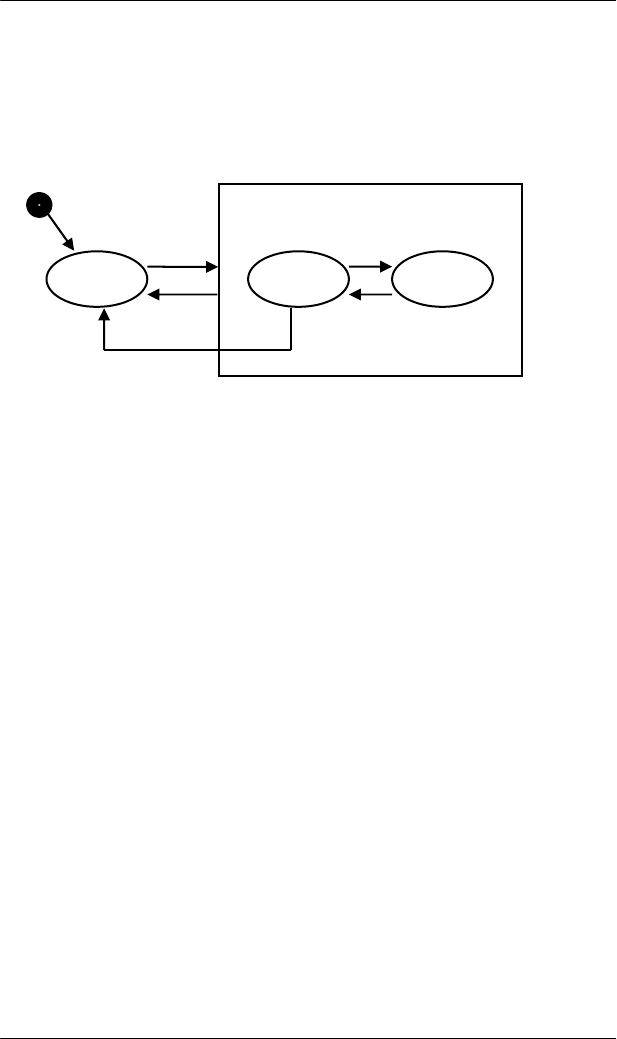
5.5 HSMS Implementation
HSMS defines the procedure for all messages exchanges between
entities across the TCP/IP. The HSMS Connection State Diagram - The
HSMS state machine is illustrated in the diagram below. The behavior
described in this diagram defines the basic requirements of HSMS:
State Description:
A - NOT CONNECTED
The entity is ready to listen for or initiate TCP/IP connections, but
either has not yet established any connections or all previously
established TCP/IP connections have been terminated.
CONNECTED
A TCP/IP connection has been established. This state has two
substates, NOT SELECTED and SELECTED.
B - NOT SELECTED
A sub state of CONNECTED in which no HSMS session has been
established or any previously established HSMS session has ended.
C - SELECTED
A sub state of CONNECTED in which at least one HSMS session has
been established. This is the normal "operating" state of HSMS: data
messages may be exchanged in this state.
1
6
2
3
4
5
A BI C
connected

5 OPERATION
38 HF80 Transponder Reader – HSMS, Release 1.3
The specification of a required TCP Application Program Interface
(API) for use in implementations is outside the scope of HSMS. A
HSMS implementation may use any TCP/IP API - sockets, TLI
(Transport Layer Interface), etc.
# Current
State Trigger New State Comment
1 ...
Local entity-specific
preparation for
TCP/IP
communication
Not
Connected
Action depends on
connection procedure to be
used: active or passive.
2 Not
connected
A TCP/IP connection
is established for
HSMS
communication.
Connected -
Not Selected None
3 Connected Breaking of TCP
connection.
Not
Connected
HSMS only permits
termination of the
connection when the
connection is in the Not
Selected sub state.
4 Not
Selected
Successful completion
of HSMS Select
procedure.
Selected
HSMS communication is
now fully established: data
messages exchange is
permitted.
5 Selected
Successful completion
of HSMS Deselect or
Separate.
Not
Selected
This transition normally
indicates the end of HSMS
communication, and so an
entity would immediately
proceed to break the TCP/IP
connection
6 Not
Selected
T7 Connection
Timeout
Not
Connected
There is a Time limit on
how long an entity is
required to remain in the
Not Selected state before
either entering in the
Selected state or returning to
Not Connected state.
OPERATION 5
39
HF80 Transponder Reader – HSMS, Release 1.3
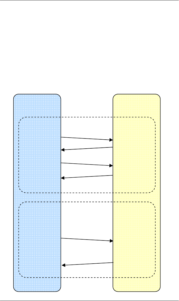
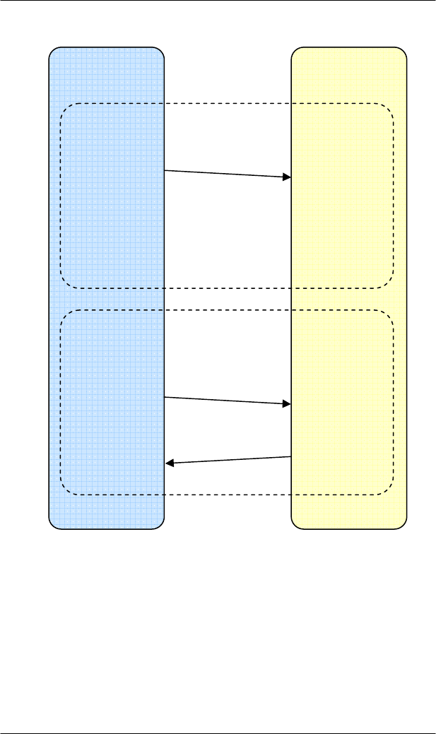
5.5.1 HSMS Message Exchange Procedures
HSMS defines the procedures for all message exchanges between
entities across the TCP/IP connection established according to the
procedures in the previous section. As explained in the overview, once
the connection is established, the two entities establish HSMS
communications with the Select procedure. The data messages may be
exchanged in any direction at any time. When the entities wish to
finish HSMS communication, the Deselect or Separate procedure is
used to terminate the HSMS communication.
Active
Entity
Passive
Entity
TCP/IP Connect
TCP/IP Accept
Connect
CONNECT
Accept
Send
Send
Receive
Receive
Select.req
Select.rsp
T6
T7
DATA
Send
Send
Receive
Receive
HSMS SECS-II
Message
(Primary)
HSMS SECS-II
Message (reply)
T3
5 OPERATION
40 HF80 Transponder Reader – HSMS, Release 1.3
Active
Entity
Passive
Entity
DISCONNECT
Send
Close
connection
Receive
Separate.req
Close
connection
LINKTEST
Send
Send
Receive
Receive
Linktest.req
Linktest.rsp
T6

OPERATION 5
41
HF80 Transponder Reader – HSMS, Release 1.3
5.5.2 HSMS Message Format
This section defines the detailed format of the messages used by the
procedures in the previous section. A HSMS Message is transmitted as
a single contiguous stream of bytes in the following order:
The minimum possible message length is 10 (Header only)
The maximum possible message length depends on SECS I specific.
5.5.3 HSMS Message Header
The Message Header is a ten byte field. The bytes in the header are
numbered from byte 0 (first byte transmitted) to byte 9. The format of
the Message Header is as follows:
Number of
Bytes Description
4 Bytes Message Length. MSB first. Specifies the number of
bytes in the Message Header plus the Message Text.
10 Bytes Message Header
0 - n Bytes
Message Text. Format is further specified by P-Type
field of message header. The message text corresponds
to message data by SECSII encoding.
Bytes Description
0 - 1 Session ID (Device ID)
2 Header Byte 2
3 Header Byte 3
4 Ptype
5 Stype
6 - 9 System Bytes

5 OPERATION
42 HF80 Transponder Reader – HSMS, Release 1.3
The physical byte order is designed to correspond as closely as
possible to the SECS-I header.
Session ID is a 16-bit unsigned integer values, which occupies bytes 0
and 1 of the header(byte 0 is MSB). Its purpose is to provide an
association by reference between control messages and subsequent
messages.
Header Byte 2 is used in different ways for different HSMS messages.
For Control Messages it contains zero or a status code. For a Data
Message it contains the W-Bit and SECS stream.
Header Byte 3 contains for control messages zero or status code. For
data messages it contains the SECS function.
P-Type is an 8 bit unsigned integer value which occupies byte 4 of the
message header and message text are encoded. Only PType = 0 is
defined by HSMS to mean SECS II message encoding. For non-zero
PType values, see "special considerations".
S-Type (Session Type) is a one-byte unsigned integer value which
occupies header byte 5.
The system bytes are used to identify a transaction uniquely among the
set of open transaction. The system bytes are also defined as in SECS-I
specific.
Value Description
0 SECS-II Encoding
1 - 127 Reserved for subsidiary standards
128 - 255 Reserved, not used
Value Description Value Description
0 Data Message 6 Linktest.rsp
1 Select.req 7 Reject.req
2 Select.rsp 8 Not used
3 Deselect.req 9 Separate.req
4 Deselect.rsp 10 Not used
5 Linktest.req 11-255 Reserved , not used

OPERATION 5
43
HF80 Transponder Reader – HSMS, Release 1.3
5.5.4 HSMS Message Format Summary
Message Header
Message Type Bytes 0 – 1
Session ID Byte 2 Byte 3 Byte 4
PType
Byte 5
SType
Bytes 6 - 9
System Bytes Message Text
Data Message *
(no R-Bit)
W-
b
it and
SECS
stream
SECS
Function 0 0
Primary:
Unique
Reply: Same
as primary
Text
Select.req * 0 0 0 1 Unique None
Select.rsp Same
as.req 0 Select
Status 0 2 Same as.req None
Deselect.req * 0 0 0 3 Unique None
Deselect.rsp Same
as.req 0 Deselect
Status 0 4 Same as.req None
Linktest.req 0xFFFF 0 0 0 5 Unique None
Linktest.rsp 0xFFFF 0 0 0 6 Same as.req None
Reject.req
Same as
message
being
rejected
PType or
Stype of
message
being
rejected
Reason
Code 0 7
Same as
message
being
rejected
None
Separate.req * 0 0 0 9 Unique None
* Indicates further specification by subsidiary standards

5 OPERATION
44 HF80 Transponder Reader – HSMS, Release 1.3
5.6 SECS-2 Implementation
5.6.1 Introduction
The SEMI Equipment Communication Standard Part 2 (SECS-2)
defines details how messages exchanged between intelligent equipment
and a host are interpreted.
It is the intent of this standard to be fully compatible with SEMI
Equipment Communication Standard E4 (SECS-1).
The messages defined in this specification support the typical activities
required for the BROOKS transponder reader.
SECS-2 gives form and meaning to messages exchanged between the
equipment and the host using a message transfer protocol, such as
SECS-1. SECS-2 defines the method of conveying information
between the equipment and the host in the form of messages.
These messages are organized into categories of activities, called
streams, which contain specific messages, called functions. In SECS-2,
messages are identified by a stream code (0-127, 7bits) and a function
code (0-255, 8 bits). Each combination of stream and function
represents a unique message identification.
SECS-2 defines the structure of messages into entities called items and
lists of items. These data structures define the logical divisions of the
message, as distinct from the physical division of the message transfer
protocol.
An item is an information packet that has a length and format defined
by the first 2, 3, or 4 bytes of the item. These bytes are called the item
header. The item header consists of the format byte and the length byte
as shown below.
Byte Name Description
0 Format and number
of the length bytes
The data format is coded in the upper 6 bits.
The two less significant bits determine the
number of the following length bytes.
1
1-2
1-3
Length-bytes
The length corresponds to the number of the
bytes of a data element. In the “List” format, the
length corresponds to the number of the list
elements.
The standard does not require the minimum
possible number of length-bytes for a given data
length
Next
<Length> Data Data bytes of a data element or number of the
data elements in case of the “List” format.

OPERATION 5
45
HF80 Transponder Reader – HSMS, Release 1.3
A list is an ordered set of elements, where an element can be either an
item or a list. The list header has the same form as an item header with
format type 0. However, the length byte refers to the number of
elements in the list rather than to the number of bytes.
5.6.2 Data Items
The formats represent arrays of types: <type>[number of elements]
where <type> is one of the following:
Oct-
Code
Hex-
Code Format Meaning Example
00 01 List
List element with the
number of the
“Length” data
elements
<L2>
<A “Hello”>
<B 0x00>
11 25 Boolean
1 – Byte Boolean
false = 00 ; true != 00 <Boolean1 0x00>
10 21 Binary
Byte sequence of the
length “Length” <B1 0x01>
20 41 ASCII
Printable ASCII
signs <A “Hello”>
31 65 I1 1 - Byte signed
Integer <I1 123>
32 69 I2 2 - Byte signed
Integer <I2 –12345>
34 71 I4 4 - Byte signed
Integer <I4 2147483647>
30 61 I8 8 - Byte signed
Integer <I8 931372980293834>
51 A5 U1 1 - Byte unsigned
Integer <U1 0>
52 A9 U2 2 - Byte unsigned
Integer <U2 #empty>
54 B1 U4 4 - Byte unsigned
Integer <U4 429489725>
50 A1 U8 8 - Byte unsigned
Integer <U8 763468676756767>
40 91 F8 8 - Byte floating
point <F8 1.223 e204>
44 81 F4 4 - Byte floating
point <F4 -1.23 >

5 OPERATION
46 HF80 Transponder Reader – HSMS, Release 1.3
Data item examples:
5.6.3 Message set
The SECSII-message-set used by the BROOKS transponder reader
consist of six different stream types.
Stream 1: (Equipment status)
- S1F1 and S1F2 Are you there request
- S1F15 and S1F16 Request offline
- S1F17 and S1F18 Request online
Stream 2: (Equipment control)
- S2F13 and S2F14 Equipment constant request
- S2F15 and S2F16 New equipment constant request
- S2F19 and S2F20 Reset send
Stream 9: (System errors)
- S9F1 Unrecognized device ID
- S9F3 Unrecognized stream type
- S9F5 Unrecognized function type
- S9F7 Illegal data
- S9F9 Transaction timer timeout
Meaning Format Length
1- Byte
Integer 65 01 xx
4- Byte
Integer 71 04 MSB ... ... LSB
ASCII 41 06 1.chr 2.chr 3.chr 4.chr 5.chr 6.chr
zero-length xx 00
List Data Item 01 03 1. element 2. element 3. element

OPERATION 5
47
HF80 Transponder Reader – HSMS, Release 1.3
According to SEMI E99 carrier ID read/writer functional standard for
SECS-1 and SECS-2 protocol, the BROOKS reader supports the
defined stream 18 messages.
Stream 18: (Equipment status)
- S18F1 and S18F2 Read attribute request
- S18F3 and S18F4 Write attribute request
- S18F5 and S18F6 Read request
- S18F7 and S18F8 Write request
- S18F9 and S18F10 Read ID request
- S18F11 and S18F12 Write ID request
- S18F13 and S18F14 Subsystem command request
- S18F65 and S18F66 Scan Transponder
- S18F67 and S18F68 Read data request – UID
- S18F69 and S18F70 Write data request – UID
- S18F71 and S18F72 Sensor State
- S18F73 and S18F74 Read ID request –UID
- S18F75 and S18F76 Write ID request – UID
- S18F77 and S18F78 Set Output State
- S18F79 and S18F80 Get Output State
- S18F85 and S18F86 Scan and Read ID request
- S18F87 and S18F88 Read Write-Counter
- S18F89 and S18F90 Read Write-Counter with UID

5 OPERATION
48 HF80 Transponder Reader – HSMS, Release 1.3
5.6.4 Data Items
This section defines the data items used in the standard SECS-2
messages described in the section “Message Details”.
Syntax:
Name: A unique name for this data item. This name is used in
the message definitions.
Format: The permitted item format code which can be used for
this standard data item. Item format codes are shown
in hex and octal, as described in section data items
(page 45). The notification “3()” indicates any of the
signed integer formats (30, 31, 32, 34).
Description: A description of the data item, with the meanings of
specific values.
Where used: The standard messages in which the data item appears.
ALARM STATUS Format: A[1]
Description: The value of the alarm status refers to the last reading
process. If a read or write error occurs, the alarm status is set. A
successful read or write resets the alarm status. When leaving
maintenance mode, the alarm status is also deleted.
0 … No alarm
1 … Alarm
Where used: STATUS

OPERATION 5
49
HF80 Transponder Reader – HSMS, Release 1.3
ATTRID Format: A[max25]
Description: Identifier for an attribute for a specific type of object.
CIDRW Attribute Definitions:
“Configuration”… Number of heads
“AlarmStatus” Current CIDRW sub state of ALARM
STATUS
“OperationalStatus” Current CIDRW sub state of
OPERATIONAL
“SoftwareRevisionLevel” Revision (version) of software - 8 byte
maximum
“CarrierIDOffset” Offset of CID in CID field (MID area)
“CarrierIDLength” Length of CID in CID field (MID area)
“S1Status” Status of external I/O 01 (read only)
“S2Status” Status of external I/O 02 (read only)
“S3Status” Status of external I/O 03 (read only)
“S4Status” Status of external I/O 04 (read only)
“S5Status” Status of external I/O 05 (read only)
“ECID_00” Æ parameter 0 – Gateway ID
“ECID_01” Æ parameter 1 – Baudrate
“ECID_02” Æ parameter 2 – Inter-Character-Timeout T1
“ECID_03” Æ parameter 3 – Block-Protocol-Timeout T2
“ECID_04” Æ parameter 4 – Reply-Timeout T3
“ECID_05” Æ parameter 5 – Inter-Block-Timeout T4
“ECID_06” Æ parameter 6 – Retry-Limit RTY
“ECID_07” Æ parameter 7 – TARGETID high Byte
“ECID_08” Æ parameter 8 – TARGETID low Byte
“ECID_09” Æ parameter 9 – Heartbeat time
“ECID_11” Æ parameter 11 – Reader ID
“ECID_12” Æ parameter 12 – Acknowledgment Error Message
“ECID_13” Æ parameter 13 – Communication Port
“ECID_16” Æ parameter 16 – antenna power level
“ECID_20” Æ parameter 20 – sensor activity
“ECID_21” Æ parameter 21 – sensor 1 delay
“ECID_22” Æ parameter 22 – sensor 2 delay
“ECID_23” Æ parameter 23 – sensor 3 delay
“ECID_24” Æ parameter 24 – sensor 4 delay

5 OPERATION
50 HF80 Transponder Reader – HSMS, Release 1.3
“ECID_25” Æ parameter 25 – sensor 5 delay
“ECID_26” Æ parameter 26 – watchport for sensor 1
“ECID_27” Æ parameter 27 – watchport for sensor 2
“ECID_28” Æ parameter 28 – watchport for sensor 3
“ECID_29” Æ parameter 29 – watchport for sensor 4
“ECID_30” Æ parameter 30 – watchport for sensor 5
“ECID_31” Æ parameter 31 – r/w max repeat
“ECID_32” Æ parameter 32 – type of transponder
“ECID_37” Æ parameter 37 – MID area
“ECID_38” Æ parameter 38 – Test after software reset
“ECID_42” Æ parameter 42 – CarrierIDOffset
“ECID_43” Æ parameter 43 – CarrierIDLength
“ECID_44” Æ parameter 44 – FixedMID
“ECID_45” Æ parameter 45 – MIDFormat
“ECID_56” Æ parameter 56 – Transmitter Delay
“ECID_57” Æ parameter 57 – Modulation
“ECID_99” Æ parameter 99 – Customer settings
“ECID100” Æ parameter 100 – DIP switches enabled
Head Attribute Definitions: *
“HeadStatus” The current state
“HeadID” Head number 01-05 (2 digits)
* In case of a HF80 Transponder Reader, the head attribute definition
“HeadStatus” is equal to the “OperationalStatus” of the CIDRW. The
“HeadID” is equal to the antenna connector.
Where used: S18F1, S18F3

OPERATION 5
51
HF80 Transponder Reader – HSMS, Release 1.3
ATTRVAL Format: A[max4]
Description: Value of the specified attribute.
CIDRW Attribute Definitions:
“Configuration” Number of heads “05”
“AlarmStatus” Current CIDRW sub state of ALARM STATUS
“0” … NO
“1” … ALARMS
“OperationalStatus” Current CIDRW sub state of OPERATIONAL
“IDLE” … reader in IDLE mode
“BUSY” … reader is busy
“MANT” … maintenance mode
“SoftwareRevisionLevel” Revision (version) of Software –
8 byte maximum
“S1Status” – “S5Status” “ON” – Sensor is occupied
“OFF” – Sensor is unoccupied
ECID_00 to ECID_99 see data item ECV parameter 0 to parameter 45
Head Attribute Definitions:
“HeadStatus” The current state
“IDLE” … reader in IDLE mode
“BUSY” … reader is busy
“NOOP”… not operating
“HeadID” Head number 01-05 (2 digits)
“01” … Antenna 1
…
“05” … Antenna 5
Where used: S18F2, S18F3

5 OPERATION
52 HF80 Transponder Reader – HSMS, Release 1.3
CPVAL Format: A[max2]
Description: State request value
“OP” … operating state
“MT” … maintenance state
Where used: S18F13
DATA Format: A [max 200]
Description: A vector or string of unformatted data. It depends on
the size of the MID area.
Where used: S18F6, S18F7, S18F68, S18F69
DATAB Format: B [max 200]
Description: Byte array of transponder data. It depends on
the size of the MID area.
Where used: S18F6, S18F7, S18F68, S18F69
DATALENGTH Format: U2
Description: Total bytes to be sent.
The DATALENGTH corresponds to the quantity of bytes that should
be read or written.
Where used: S18F5, S18F7, S18F67, S18F69

OPERATION 5
53
HF80 Transponder Reader – HSMS, Release 1.3
DATASEG Format:A[2]
Description: Used to identify the data requested.
The DATASEG corresponds to the page number (PAGEID) of the ISO
15693 transponder.
“00”: First page of any type of transponder or first page of the
DATA area.
Where used: S18F5, S18F7, S18F67, S18F69
DATASEGB Format:B[1]
Description: Used to identify the data requested.
The DATASEG corresponds to the real byte of the ISO 15693
transponder.
Empty First byte of DATA area (depends on MID settings).
Where used: S18F5, S18F7, S18F67, S18F69
EAC Format: B[1]
Acknowledge code for new reader constant
0 … Parameter was set successfully
1 … Parameter could not be set
Where used: S2F16
ECID Format: U1
Parameter number of reader (see data item ECV)
Where used: S2F13, S2F15

5 OPERATION
54 HF80 Transponder Reader – HSMS, Release 1.3
ECV Format: U1
Reader parameter definition.
The values are displayed as decimal values!
Where used: S2F14, S2F15
Parameters:
Parameter 0: Gateway ID
The gateway ID is a part of the device ID. The BROOKS reader works
simultaneously as a gateway and a reader (CIDRW with integrated
head).
It is the “lower message ID” in the message header.
00 .. 255
Default: 0x00
Parameter 1: Baudrate
Data transmission rate to the SECS-Host
12: 1200 Baud
24: 2400 Baud
48: 4800 Baud
96: 9600 Baud
192: 19200 Baud
200: 38400 Baud
201: 57600 Baud
Default :(192) 19200 Baud (see accompanying letter of the reader)
Parameter 2: Inter-Character-Timeout T1
1 .. 100 1/10s
Default: (10) 1s

OPERATION 5
55
HF80 Transponder Reader – HSMS, Release 1.3
Parameter 3 : Block-Protocol-Timeout T2
2 .. 250 1/10s
Default: (20) 2s
Parameter 4: Reply-Timeout T3
1 .. 120 1s
Default: (45) 45s
Parameter 5: Inter-Block Timeout T4
This parameter is ineffective if the used messages are not larger than
one block.
1 .. 120 1s
Default: (45) 45s
Parameter 6: Retry limit RTY
Number how often a question or a message shall be repeated.
0 .. 31
Default: 3
Parameter 7: TARGETID HighByte
Highbyte of the predefined TARGETID (not changeable).
Parameter 8: TARGETID LowByte
Lowbyte of the predefined TARGETID (not changeable).
Parameter 9: Heartbeattime
The reader offers the option of generating a regular heartbeat. This
means the reader sends a S1F1 message to the host in the defined
interval.
0 … No heartbeat
1 … 255 10s (10s - 2550s)
Default: 0 no heartbeat

5 OPERATION
56 HF80 Transponder Reader – HSMS, Release 1.3
Parameter 10: Not defined!
Parameter 11: Reader-ID
The reader ID is a part of the device ID. In the message header, it
corresponds to the 7 LSB (last significant bits) of the “upper message
ID”.
00 .. 127
Default: 0x00
The BROOKS reader works as a gateway (CIDRW) with up to 5
integrated heads. Therefore the reader ID is predefined as 0x00. Of
course, the ID can be changed within the valid scope.
Parameter 12: Acknowledgment Error Message
Defines whether an error message has to be confirmed by the host or
not.
0 – no confirmation expected
1 – confirmation expected
default: 1

OPERATION 5
57
HF80 Transponder Reader – HSMS, Release 1.3
Parameter 13: Communication port
The communication with the host can be done by by HSMS (TCP/IP)
or optional by SECS1 (RS232) interface. The following options are
possible:
0x11: Host Æ Reader: HSMS
Reader Æ Host: HSMS
0x22: Host Æ Reader: SECS1
Reader Æ Host: SECS1
The setting of the DIP switch 1 affects this parameter! The
setting of the DIP switch has priority and will be stored in
the parameter after a reset.
Attention! If the reader has only one interface (TCP/IP or RS232)
the changing of parameter 13 to a value where the not
installed interface option will be activated and the DIP
switch 1 is deactivated will set the reader to a mode
where no communication with the reader is possible.
Then the parameter can not be switched back to correct
value.
default: (0x11) Ethernet
Parameter 14, 15, 17, 18 and 19 are not defined!
Parameter 16: Antenna Power Level
Defines the power level at antenna. Minimum 200mW and maximum
1000mW.
00 .. 31
default: 0x1F (highest power)

5 OPERATION
58 HF80 Transponder Reader – HSMS, Release 1.3
Parameter 20: sensor activity
The transponder reader offers the option of deactivating the connected
sensors.
0x00000000 all 5 Sensors deactivated
0x00000001 Sensor 1 activated
0x00011111 all 5 Sensors activated
Default: 0x00011111 (31)
Parameter 21: sensor delay for presence sensor 1
Delay time for sensor signal to start a defined action.
0 .. 255 1/10 s
Default: (10) 1s
Parameter 22: sensor delay for presence sensor 2
Delay time for sensor signal to start a defined action.
0 .. 255 1/10 s
Default: (10) 1s
Parameter 23: sensor delay for presence sensor 3
Delay time for sensor signal to start a defined action.
0 .. 255 1/10 s
Default: (10) 1s
Parameter 24: sensor delay for presence sensor 4
Delay time for sensor signal to start a defined action.
0 .. 255 1/10 s
Default: (10) 1s
Parameter 25: sensor delay for presence sensor 5
Delay time for sensor signal to start a defined action.
0 .. 255 1/10 s

OPERATION 5
59
HF80 Transponder Reader – HSMS, Release 1.3
Default: (10) 1s

5 OPERATION
60 HF80 Transponder Reader – HSMS, Release 1.3
Parameter 26: watchport for presence sensor 1
Enables a message to the host if a cassette/FOUP is detected on the I/O
port, or if it is removed from I/O port.
A sensor is required to use this capability!
Bit 0: 0 – Report cassette/FOUP removed is disabled
1 – Report cassette/FOUP removed is enabled
Bit 1: 0 – Report cassette/FOUP detected is disabled
1 – Report cassette/FOUP detected is enabled
Bit 2 – 5: not used!
Bit 6: 0 – Message S18F71 expects no reply message
1 – Message S18F71 expects a reply message
Bit 7: 0 – The input signal is not inverted (normal)
1 – The input signal is inverted
Input signal is normal(Bit 7) and no reply is expected (Bit 6):
0x00000000 Report nothing
0x00000001 Report cassette/FOUP is removed
0x00000010 Report cassette/FOUP is detected
0x00000011 Report cassette/FOUP is detected and cassette
is removed
Input signal is inverted (Bit 7) and a reply is expected (Bit 6):
0x11000000 Report nothing
0x11000001 Report cassette/FOUP is removed
0x11000010 Report cassette/FOUP is detected
0x11000011 Report cassette/FOUP is detected and cassette
is removed
Default: 0x00000011 (3)

OPERATION 5
61
HF80 Transponder Reader – HSMS, Release 1.3
Parameter 27: watchport for presence sensor 2
See parameter 26.
Parameter 28: watchport for presence sensor 3
See parameter 26.
Parameter 29: watchport for presence sensor 4
See parameter 26.
Parameter 30: watchport for presence sensor 5
See parameter 26.
Parameter 31: r/w maxrepeat
If a read/write error occurs, this parameter defines the maximum
number of attempts to read or write a transponder.
0 .. 5
Default: 5
Parameter 32: type of transponder
Defines the type of tag. The type is used in case of some reading and
writing messages which do not use the UID to identify the type of the
tag. Therefore, the device has to know the type of tag before trying to
read or write. If a tag of another type supports the same messages like
the defined type, the reader can read/write this tag too.
0x04 … Philips ICS20
0x05 … Infineon tag
0x07 … TI tag (Tag-it)
0x85 … Infineon My D Light
Default: 5 (Infineon tag)

5 OPERATION
62 HF80 Transponder Reader – HSMS, Release 1.3
Parameter 37: MID area
This parameter defines the range of the MID.
‘0’ … ‘10’ pages
Default: ‘4’ – MID area = 4 pages = 16 bytes (depends on
transponder type).
See also parameter 42 – 45 and 99.
Parameter 38: Test After Soft Reset
This parameter enables/disables the initial test after a software reset.
0x00 No initial test after software reset
0x01 Initial test after software reset
0x11 polling Inventory on head 1 after software reset
0x12 polling Inventory on head 2 after software reset
0x13 polling Inventory on head 3 after software reset
0x14 polling Inventory on head 4 after software reset
0x15 polling Inventory on head 5 after software reset
0x21 polling read and write on head 1 after software reset
0x22 polling read and write on head 2 after software reset
0x23 polling read and write on head 3 after software reset
0x24 polling read and write on head 4 after software reset
0x25 polling read and write on head 5 after software reset
Default: (0) No initial test after software reset
OPERATION 5
63
HF80 Transponder Reader – HSMS, Release 1.3
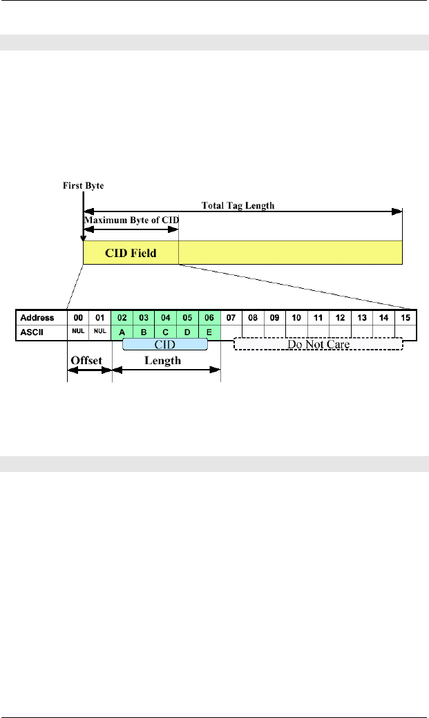
Parameter 42: CarrierIDOffset
Defines the offset of the CID within the CID field (MID area –
parameter 37).
The valid value range depends on the value of the MID area and the
value of CarrierIDLength.
Valid range: 0 … maximum bytes of CID -1
Default: 0
Offset + Length can not be larger than the length of CID field.
Parameter 43: CarrierIDLength
Defines the length of the CID within the CID field (MID area –
parameter 37).
The valid value range depends on the value of the MID area and the
value of CarrierIDOffset. (see parameter 42: CarrierIDOffset)
Valid range: 1 … maximum bytes of CID field
Default: 16

5 OPERATION
64 HF80 Transponder Reader – HSMS, Release 1.3
Parameter 44: FixedMID
Defines the read, write and error behavior regarding CarrierIDLength
defined in SEMI E99-0303.
0 Dynamic CID length (to ensure compatibility with
older versions)
MID length is variable for writing to the tag.
Reading up to the first non-visible ASCII character.
1 Fixed CID length (to meet the new standard revision)
Length of MID in the tag must be the same as the
reader settings. If there is a non-visible ASCII
character within the CID field, an error occurs.
Default: 0
Parameter 45: MIDFormat
Defines the physical format of the MID data in the transponder
memory.
0 E99 standard format left aligned – meets the requirement
of the SEMI standard E99
1 MID format right aligned – filler byte is ASCII ‘0’ (0x30)
Reading: leading ‘0’ will displayed.
2 MID format right aligned – filler byte is ASCII ‘0’ (0x30)
Reading: leading ‘0’ will not displayed.
If parameter 45 is not ‘0’ the parameters 42, 43 and 44 are
not effective.
Default: 0

OPERATION 5
65
HF80 Transponder Reader – HSMS, Release 1.3
Examples: MID string is ‘123456789ABC’
Parameter 45 = ‘0’:
tag memory:
Page 3, 4 9 A B C 0x00 0x00 0x00 0x00
Memory address 15 14 13 12 11 10 9 8
Page 1, 2 1 2 3 4 5 6 7 8
Memory address 7 6 5 4 3 2 1 0
Æ Output string: ‘123456789ABC’
Parameter 45 = ‘1’ or ‘2’:
tag memory:
Page 3, 4 0 0 0 0 1 2 3 4
Memory address 15 14 13 12 11 10 9 8
Page 1, 2 5 6 7 8 9 A B C
Memory address 7 6 5 4 3 2 1 0
Æ Output string (parameter 45 = ‘1’): ‘0000123456789ABC’
Æ Output string (parameter 45 = ‘2’): ‘123456789ABC’

5 OPERATION
66 HF80 Transponder Reader – HSMS, Release 1.3
Parameter 99: custom code
If the customer requires special parameter settings that deviate from
the default values, a customer code can be assigned by BROOKS to set
several parameter values via one parameter. Parameter 99 will not be
stored in the reader and can not be read out. The following values are
defined to change several parameters in one step.
0x04 … Settings for Philips ICS20 tag
0x05 … Settings for Infineon tag
0x07 … Settings for TI tag (Tag-it)
0x85 … Settings for Infineon My D Light
0x00 … Resets all parameters to default settings
) Attention! After reset all parameter to default settings the
reader performs a hardwarereset!
These settings change the following parameters:
Parameter 99 = 0x04
Parameter# Value
32 – Tag type 0x04
37 – MID area 0x04
53 – Readmode Low
54 – Writemode Low
Parameter 99 = 0x05
Parameter# Value
32 – Tag type 0x05
37 – MID area 0x02
53 – Readmode Low
54 – Writemode High

OPERATION 5
67
HF80 Transponder Reader – HSMS, Release 1.3
Parameter 100: (0x64) DIP-Switch Enabled
Defines which DIP switches are enabled and have influence to the
behavior.
Via bit 0 to bit 3 the individual DIP switches can be enabled or
disabled.
Attention! Have a look to parameter 13 and value of DIP switch 1
before changing this value!
0 – 0x0F
default: 0x0F
Parameter 123: (0x7B) Fineversion
Can be used to request the fineversion of the firmware.
MDLN Format: A[6]
Equipment model number.
Where used: S1F2
Parameter 99 = 0x07
Parameter# Value
32 – Tag type 0x07
37 – MID area 0x04
53 – Readmode Low
54 – Writemode High
Parameter 99 = 0x85
Parameter# Value
32 – Tag type 0x85
37 – MID area 0x04
53 – Readmode Low
54 – Writemode Low

5 OPERATION
68 HF80 Transponder Reader – HSMS, Release 1.3
MHEAD Format: B[10]
SECS message block header associated with message block in error.
Where used: S9F1, S9F3, S9F5, S9F7
MID Format: A
Description: Material ID
Depending on the type of transponder, it is possible to modify the
length of the MID.
MID length can be set from “0” (no MID) to “10” (MID occupies the
first 10 pages (writeable)) See parameter 37.
Where used: S18F10, S18F11, S18F74, S18F75
OFLACK Format: B[1]
Acknowledge code for OFF-LINE request.
0 … OFF-LINE acknowledge (reader is offline)
Where used: S1F16
ONLACK Format: B[1]
Acknowledge code for ON-LINE request.
0 … ON-LINE accepted (reader is online)
Where used: S1F18

OPERATION 5
69
HF80 Transponder Reader – HSMS, Release 1.3
OUTPUT Format: A[2]
Number of the output of the antenna head indicated by TARGETID.
“01” … Output 1
“02” … Output 2
Where used: S18F77
PM Information Format: A[2]
Description: Preventive maintenance information
“NE” … Normal execution
“MR” … Maintenance required
Where used: STATUS
RAC Format: B[1]
Reset acknowledge code.
0 … Reset to be done
1 … Reset could not be done
Where used: S2F20
RIC Format: B[1]
Reset code.
1 … Power up reset
2 … Software reset (without reset of Ethernet component)
Where used: S2F19

5 OPERATION
70 HF80 Transponder Reader – HSMS, Release 1.3
SHEAD Format: B[10]
Stored SECS message block header. Only the last message is stored,
which must still be confirmed by the host!
Where used: S9F9
SOFTREV Format: A[max 6]
Software revision code.
Where used: S1F2
SSACK Format: A[2]
Description: Result information on the status of the request
concerning the service request.
“NO” … Normal operation
Indicates the success of the requested action
“EE” … Execute error
Cannot read tag data . Cannot read ID
sequence. But equipment is normal.
“CE” … Communication error
Syntax error of message or message format or
value.
“HE” … Hardware error
ID reader/writer head fault, ID reader/writer
head is powered off.
“TE” … Tag error
Where used: S18F2, S18F4, S18F6, S18F8, S18F10, S18F12, S18F14,
S18F66, S18F68, S18F70, S18F72, S18F74, S18F76,
S18F78, S18F80

OPERATION 5
71
HF80 Transponder Reader – HSMS, Release 1.3
SSCMD Format: A[max18]
Description: Indicates an action to be performed by the subsystem.
Used to differentiate between the different subsystem commands
indicated.
“ChangeState” … Change state
“GetStatus” … Get state
“PerformDiagnostics” … Perform diagnostics
“Reset” … Reset CIDRW
Where used: S18F13
SSTATE Format: A[max 3]
Description: Provides status information of the external I/O of a
specific head.
“ON” - Sensor is occupied
“OFF” - Sensor is unoccupied
Where used: S18F71
STATE Format: A[max 5]
Description: State of the external outputs of a specific head.
“ON” … Output is ON
“OFF” … Output is OFF
“FLASH” … Output is flashing
“KEEP” … Output remains current state
Where used: S18F77

5 OPERATION
72 HF80 Transponder Reader – HSMS, Release 1.3
STATUS Format: A[2]
Description: Provides status information of a subsystem
component.
Consists of PM Information and the current values of
the CIDRW attributes AlarmStatus, OperationalStatus,
and HeadStatus.
List of a Status
L,4
<PMInformation>
<AlarmStatus>
<OperationalStatus>
<HeadStatus>
For data items OperationalStatus and HeadStatus see data item
ATTRVAL.
Where used: S18F2, S18F4, S18F8, S18F10, S18F12, S18F14,
S18F70, S18F74, S18F76, S18F78, S18F80

OPERATION 5
73
HF80 Transponder Reader – HSMS, Release 1.3
TARGETID Format: A[max10]
Description: Identifies where a request for action or data is to be
applied. The TARGETID corresponds to the last four
characters of the serial number on a label on top of the
reader.
The reader uses the 2 digit HeadID as TARGETID
to address the right antenna connector.
See also reader parameter definitions (data item ECV)
parameter 7 and 8.
Example : “H8-xxxx-TS” (xxxx … dependent on the individual
reader)
The 4 ASCII character TARGETID xxxx is set by
delivery (is used as serial number).
The predefined TARGETID is fixed and cannot be
changed.
The 2 ASCII character HeadID corresponds to the
antenna connectors 01 - 05.
Where used: all stream 18 messages
UID Format: B[8-12]
Description: Unified identifier of the tag.
In case of ISO15693 the UID has a length of 8 Bytes.
Where used: S18F66, S18F67, S18F69, S18F73, S18F75

5 OPERATION
74 HF80 Transponder Reader – HSMS, Release 1.3
Write Counter Format: B[4]
Description: Write Counter. Part of Tag data which counts the
number of write actions to this specific tag.
Where used: S18F88, S18F90
Write Counter Length Format: U1
Description: Length of write counter data on tag.
Where used: S18F87, S18F89

OPERATION 5
75
HF80 Transponder Reader – HSMS, Release 1.3
5.7 SEMI E99
5.7.1 Introduction
The purpose of the Carrier ID Reader/Writer functional standard is to
provide a common specification for concepts, behavior, and services
provided by a Carrier ID Reader/Writer to an upstream controller. A
standard interface will increase the interchangeability of a Carrier ID
Reader/Writer, so that users and equipment suppliers have a wide
range of choice.
Scope:
1. The interface standard addresses the functional requirements for
a generic Carrier ID Reader/Writer interface with an upstream
controller.
2. The specification includes the required behavior and required
communications for a Carrier ID Reader and Writer.
3. The specification does not require, define or prohibit
asynchronous messages sent by the Carrier ID Reader or Writer.
4. This standard does not purport to address safety issues, if any,
associated with its use.
5.7.2 State Models
To facilitate independent control of the individual heads, there are two
separate state models defined, one for CIDRW subsystem and one for
each individual head. The BROOKS reader combines the CIDRW
subsystem with the head.
The state model for the BROOKS reader is displayed in the state model
below.

5 OPERATION
76 HF80 Transponder Reader – HSMS, Release 1.3
The table below defines the states of the BROOKS transponder reader.
State Definition
ALARM STATUS Displays the presence or absence of alarms.
ALARMS An alarm condition exists.
BUSY A service is being performed that affects the state of
the hardware
CIDRW Super-state of CIDRW state model. Always active
when the CIDRW is powered on.
IDLE No service is performed. All heads are idle.
INITIALIZING
CIDRW is performing initialization and self
diagnostic. Presence or absence of alarms is initially
determined in this state.
NO ALARMS No alarm condition exists.
OPERATING Normal operational states where reading and/or
writing operations can be performed
OPERATIONAL STATUS The CIDRW is fully capable of performing all services
that it supports.
RUNNING The CIDRW is operational and able to communicate.
MAINTENANCE Internal setup and maintenance activities.
INITIALIZING
OPERATING
IDLE BUSY
MAINTENANCE
NO ALARMS
A
LARMS
RUNNING
OPERATIONAL STATUS
A
LARM STATUS
1
2
4
3
5
6 7
8
9 10

OPERATION 5
77
HF80 Transponder Reader – HSMS, Release 1.3
The table below defines the transitions of the BROOKS SECS-1 state
model of the transponder reader.
# Previous State Trigger New State Actions Comment
1 Any Power up or reset INITIALIZING
Initialize
hard- and
software
Default entry on
power up
2 INITIALIZING
Initialization is
complete RUNNING None
The CIDRW is
now able to
communicate
3 INITIALIZING
Default entry into
OPERATING IDLE None Internal
4 IDLE
A service request
to read or write or
perform
diagnostic
is received.
BUSY None
5 BUSY
All services
request that affect IDLE None
6 IDLE
A user selects the
MAINTENANCE
state and all
heads are IDLE
MAINTENANCE None
The upstream
controller may
send a request or
the operator may
set a switch to
select the
MAINTENANCE
state.
Maintenance and
setup activities
may now be
performed.
7 MAINTENANCE
A user selects the
OPERATING
state and all
heads are IDLE
IDLE None
The upstream
controller may
send a request or
the operator may
set a switch to
select the
OPERATING
state. Normal
operating
activities may
now be
performed.
8 INITIALIZING
Default entry into
ALARM
STATUS
ALARMS or
NO ALARMS None
9 NO ALARMS
An alarm
condition is
detected.
ALARMS None
10 ALARMS
All alarm
conditions have
cleared.
NO ALARMS None
11 Any
A reset service
request is
received
CIDRW None

5 OPERATION
78 HF80 Transponder Reader – HSMS, Release 1.3
5.7.3 Valid Services per State
The following table shows which of the various services can be
performed by the reader when the reader is in various individual states.
Service
Write ID
Write Data
Set Attributes
Reset
Read ID
Read Data
Perform Diag.
Get Status
Get Attributes
Change State
Reader State
INIT
IDLE/BUSY X X X X X X X X X
MANT X X X X X X X X
) Note that when in the initializing state after power up or the
reset service, the CIDRW may not be able to communicate.
5.8 Message Details
5.8.1 Equipment status
S1F0: ABORT TRANSACTION (reader <-> host)
Used instead of an expected reply to abort a transaction. Function 0 is
defined in every stream and has the same meaning in every stream.
S1F0 W . * Header Only
S1F1: ARE YOU THERE REQUEST (reader <-> host, reply)
Establishes if the gateway/reader or host is online.
S1F1 W . * Header Only
S1F2: ON-LINE DATA (host -> reader)
The host signifies that it is online.
S1F2
<L[2]
<MDLN >
<SOFTREV >
>.

OPERATION 5
79
HF80 Transponder Reader – HSMS, Release 1.3
S1F2: ON-LINE (reader -> host)
The reader signifies that it is online.
S1F2
<L[2]
<MDLN >
<SOFTREV >
>.
S1F15: REQUEST OFF_LINE (host ->reader, reply)
The reader is requested to change the communication state to offline.
The reader can only be set online again by using message S1F17 (or
reset S2F19), all other messages will be aborted by the SxF0 message!
S1F15 W. *Header Only
S1F16: OFFLINE ACKNOWLEDGE (reader -> host)
Acknowledge.
S1F16
<OFLACK>.
S1F17: REQUEST ON_LINE (host ->reader, reply)
The reader is requested to change the communication state to online.
S1F17 W. *Header Only
S1F18: ONLINE ACKNOWLEDGE (reader -> host)
Acknowledge.
S1F18
<ONLACK>.

5 OPERATION
80 HF80 Transponder Reader – HSMS, Release 1.3
5.8.2 Equipment Control
S2F0: ABORT TRANSACTION (reader <-> host)
Used instead of an expected reply to abort a transaction. Function 0 is
defined in every stream and has the same meaning in every stream.
S2F0 W . * Header Only
S2F13: EQUIPMENT CONSTANT REQUEST
(host-> reader, reply)
The host requests one constant from the reader.
S2F13 W
<L[1]
<ECID>
>.
S2F14: EQUIPMENT CONSTANT DATA (reader -> host)
The reader sends the requested constant to the host.
S2F14
<L[1]
<ECV>
>.
S2F15: NEW EQUIPMENT CONSTANT SEND
(host-> reader, reply)
The host changes one reader constant.
S2F15 W
<L[1]
<L[2]
<ECID>
<ECV>
>
>.

OPERATION 5
81
HF80 Transponder Reader – HSMS, Release 1.3
S2F16: NEW EQUIPMENT CONSTANT ACKNOWLEDGE
(reader -> host)
The reader acknowledges the setting of the reader constant.
S2F16
< EAC>.
S2F19: RESET SEND (host -> reader, reply)
The host requests the reader to reset the hardware and software.
If a heartbeat time is set (parameter 9) the reader sends a S1F1
message when the reset was finished.
The power up reset requires a few seconds.
S2F19 W
< RIC>.
S2F20: RESET ACKNOWLEDGE (reader -> host)
The reader acknowledges the reset (only in case of software reset).
In case of a power up reset, the reader sends no S2F20 message.
S2F20
< RAC>.

5 OPERATION
82 HF80 Transponder Reader – HSMS, Release 1.3
5.8.3 System Errors
S9F1: UNRECOGNIZED DEVICE ID (reader -> host)
The device ID in the message block header does not correspond to the
equipment device ID.
S9F1
< MHEAD > .
S9F3: UNRECOGNIZED STREAM TYPE (reader -> host)
The reader does not recognize the stream type in the message block
header.
S9F3
< MHEAD > .
S9F5: UNRECOGNIZED FUNCTION TYPE (reader -> host)
The reader does not recognize the function number in the message
block header.
S9F5
< MHEAD > .
S9F7: ILLEGAL DATA (reader -> host)
The reader does not recognize the data in the message.
S9F7
< MHEAD > .
S9F9: TRANSACTION TIMER TIME-OUT (reader -> host)
This message indicates that a transaction timer has timed out and that
the corresponding transaction was aborted. Only the last sent message
(which must be confirmed by the host) is stored and controlled.
S9F9
< SHEAD > .

OPERATION 5
83
HF80 Transponder Reader – HSMS, Release 1.3
5.8.4 Subsystem Control and Data
S18F0: ABORT TRANSACTION (reader <-> host)
Used instead of an expected reply to abort a transaction. Function 0 is
defined in every stream and has the same meaning in every stream.
S18F0 W . * Header Only
S18F1: READ ATTRIBUTE REQUEST (RAR) (host -> reader,
reply)
This message requests the current values of specific attributes of the
subsystem component indicated in TARGETID.
S18F1 W
L,2
1. <TARGETID>
2. L,n
1. <ATTRID1>
…
n. <ATTRIDn>
S18F2: READ ATTRIBUTE DATA (RAD) (reader -> host)
This message returns the current values of the requested attributes and
the current status of the requested component indicated in TARGETID.
S18F2
L,4
1. <TARGETID>
2. <SSACK>
3. L,n
1. <ATTRVAL1>
…
n. <ATTRVALn>
4. L,1
L,s
1. <STATUS1>
…
s. <STATUSs>
If the ATTRID of the S18F1 message is unknown, the corresponding
ATTRVAL has the value <nothing>.

5 OPERATION
84 HF80 Transponder Reader – HSMS, Release 1.3
S18F3: WRITE ATTRIBUTE REQUEST (WAR)
(host -> reader, reply)
This message requests the subsystem to set the value of read/write
attributes of the component specified in TARGETID.
S18F3 ,W
L,2
1. <TARGETID>
2. L,n
1. L,2
1. <ATTRID1>
2. <ATTRVAL1>
…
n. L,2
1. <ATTRIDn>
2. <ATTRVALn>
S18F4: WRITE ATTRIBUTE ACKNOWLEDGE (WAA)
(reader -> host)
This message acknowledges the success or reports failure of the
request to write attribute data to the subsystem indicated in
TARGETID.
S18F4
L,3
1. <TARGETID>
2. <SSACK>
3. L,1
L,s
1. <STATUS1>
…
s. <STATUSs>
If the ATTRID of the S18F3 message is unknown, a communication
error (CE) occurs.

OPERATION 5
85
HF80 Transponder Reader – HSMS, Release 1.3
S18F5: READ REQUEST (RR) (host -> reader, reply)
The host requests the subsystem indicated in TARGETID to read
information. DATASEG may be used to indicate a specific section of
data to be read. DATALENGTH is used to limit the amount of data for
that section.
S18F5 W
L,3
1. <TARGETID>
2. <DATASEG>
3. <DATALENGTH>
If DATASEG and DATALENGTH are both omitted (zero length
items) then up to 200 bytes of the data area are requested. If only
DATALENGTH is omitted, then all data within the indicated section
are requested.
S18F6: READ DATA (RD) (reader -> host)
This message is used to return requested information from the
subsystem indicated in TARGETID, or to acknowledge the result of
the request.
S18F6
L,3
1. <TARGETID>
2. <SSACK>
3. <DATA>
If TARGETID is unknown, then a communication error (CE) occurs.

5 OPERATION
86 HF80 Transponder Reader – HSMS, Release 1.3
S18F5: READ REQUEST BINARY (RR) (host -> reader, reply)
The host requests the subsystem indicated in TARGETID to read
information. DATASEGB may be used to indicate a specific section of
data to be read. DATALENGTH is used to limit the amount of data for
that section.
S18F5 W
L,3
1. <TARGETID>
2. <DATASEGB>
3. <DATALENGTH>
If DATASEGB and DATALENGTH are both omitted (zero length
items) then up to 200 bytes of the data area are requested. If only
DATALENGTH is omitted, then only one byte starting from
DATASEGB is requested.
S18F6: READ DATA (RD) (reader -> host)
This message is used to return requested information from the
subsystem indicated in TARGETID, or to acknowledge the result of
the request.
S18F6
L,3
1. <TARGETID>
2. <SSACK>
3. <DATAB>
If TARGETID is unknown, then a communication error (CE) occurs.

OPERATION 5
87
HF80 Transponder Reader – HSMS, Release 1.3
S18F7: WRITE DATA REQUEST (WAR) (host -> reader, reply)
This message requests to write data to the subsystem component
indicated in TARGETID. DATASEG may be used to indicate a
specific section of the data area to be written or overwritten.
S18F7 W
L,4
1. <TARGETID>
2. <DATASEG>
3. <DATALENGTH
4. <DATA>
If DATASEG and DATALENGTH are both omitted (zero length
items), then up to 200 bytes in the data area are to be overwritten. If
only DATALENGTH is omitted or if DATALENGTH has a value of
zero, then all data within the indicated section are to be written.
If DATASEG is omitted (zero length items) the value of
DATALENGTH set the length of data that shall be written. If the
length of the data that shall be written is longer than the value of
DATALENGTH, a communication error (CE) occurs.
S18F8: WRITE DATA ACKNOWLEDGE (WDA) (reader -> host)
This message acknowledges the success or failure of writing data to
the subsystem indicated in TARGETID.
S18F8
L,3
1. <TARGETID>
2. <SSACK>
3. L,1
L,s
1. <STATUS1>
…
s. <STATUSs>
If the TARGETID is unknown, a communication error (CE) occurs.

5 OPERATION
88 HF80 Transponder Reader – HSMS, Release 1.3
S18F7: WRITE DATA REQUEST BINARY (host -> reader, reply)
This message requests to write data to the subsystem component
indicated in TARGETID. DATASEGB may be used to indicate a
specific section of the data area to be written or overwritten.
S18F7 W
L,4
1. <TARGETID>
2. <DATASEGB>
3. <DATALENGTH
4. <DATAB>
If DATASEGB and DATALENGTH are both omitted (zero length
items), then length of DATAB will be written to the tag. If length of
DATAB is smaller than 200 bytes the rest of the 200 bytes will be
filled up with 0x00. If only DATALENGTH is omitted then the first
byte or only byte of DATAB starting from DATASEGB will be
written.
If DATASEGB is omitted (zero length items) the value of
DATALENGTH set the length of data that shall be written.
S18F8: WRITE DATA ACKNOWLEDGE BINARY (reader ->
host)
This message acknowledges the success or failure of writing data to
the subsystem indicated in TARGETID.
S18F8
L,3
1. <TARGETID>
2. <SSACK>
3. L,1
L,s
1. <STATUS1>
…
s. <STATUSs>
If the TARGETID is unknown, a communication error (CE) occurs.

OPERATION 5
89
HF80 Transponder Reader – HSMS, Release 1.3
S18F9: READ ID REQUEST (RIR) (host -> reader, reply)
This message is used to request the subsystem indicated by
TARGETID to read the MID.
S18F9,W
<TARGETID>
S18F10: READ ID DATA (RID) (reader -> host)
This message returns a requested material identifier MID as read by
the subsystem indicated in TARGETID.
S18F10
L,4
1. <TARGETID>
2. <SSACK>
3. <MID>
4. L,1
L,s
1. <STATUS1>
…
s. <STATUSs>
The reader can be in operational or maintenance mode to
read the MID with message S18F9.

5 OPERATION
90 HF80 Transponder Reader – HSMS, Release 1.3
S18F11: WRITE ID REQUEST (WIR) (host -> reader, reply)
This message is used to request the subsystem indicated by
TARGETID to write the MID.
S18F11 W
L,2
1. <TARGETID>
2. <MID>
Pay attention: The reader must be in maintenance mode to
write the MID with message S18F11.
S18F12: WRITE ID ACKNOWLEDGE (WIA) (reader -> host)
This message acknowledges the success or failure of writing the MID
to the subsystem indicated in TARGETID.
S18F12
L,3
1. <TARGETID>
2. <SSACK>
3. L,1
L,s
1. <STATUS1>
…
s. <STATUSs>
If the TARGETID is unknown a communication error (CE) occurs.

OPERATION 5
91
HF80 Transponder Reader – HSMS, Release 1.3
S18F13: SUBSYSTEM COMMAND REQUEST (SCR)
(host -> reader, reply)
This message is used to request the subsystem indicated in TARGETID
to perform a specific action.
S18F13 W
L,3
1. <TARGETID>
2. <SSCMD>
3. L,n
1. <CPVAL>
…
n. <CPVALn>
S18F14: SUBSYSTEM COMMAND ACKNOWLEDGE (SCA)
(reader -> host)
This message reports the result from the subsystem specified in
TARGETID for the requested action.
S18F14
L,3
1. <TARGETID>
2. <SSACK>
3. L,1
L,s
1. <STATUS1>
…
s. <STATUSs>
If the TARGETID is unknown, a communication error (CE) occurs.

5 OPERATION
92 HF80 Transponder Reader – HSMS, Release 1.3
S18F65: SCAN TRANSPONDER REQUEST (STR)
(host -> reader, reply)
This message is used to request the subsystem indicated in TARGETID
to perform a scan.
S18F65 W
<TARGETID>
S18F66: SCAN TRANSPONDER ACKNOWLEDGE (STA)
(reader -> host)
This message reports the result from the subsystem specified in
TARGETID for the requested action.
S18F66
L,3
1. <TARGETID>
2. <SSACK>
3. L,s
1. <UID1>
…
s. <UIDs>
If the TARGETID is unknown, a communication error (CE) occurs.
The action returns a UID list of all ISO-tags found in the reading
range.

OPERATION 5
93
HF80 Transponder Reader – HSMS, Release 1.3
S18F67: READ REQUEST UID (RRU) (host -> reader, reply)
The host requests the subsystem indicated in TARGETID to read
information from the transponder indicated in UID. DATASEG may be
used to indicate a specific section of data to be read. DATALENGTH
is used to limit the amount of data for that section.
S18F67 W
L,4
1. <TARGETID>
2. <UID>
3. <DATASEG>
4. <DATALENGTH>
If DATASEG and DATALENGTH are both omitted (zero length
items) then up to 200 bytes of the data area are requested. If only
DATALENGTH is omitted, then all data within the indicated section
are requested.
S18F68: READ DATA UID (RDU) (reader -> host)
This message is used to return requested information from the
subsystem indicated in TARGETID and the transponder indicated in
UID, or to acknowledge the result of the request.
S18F68
L,3
1. <TARGETID>
2. <SSACK>
3. <DATA>
If TARGETID is unknown, then a communication error (CE) occurs.

5 OPERATION
94 HF80 Transponder Reader – HSMS, Release 1.3
S18F67: READ REQUEST UID BINARY (host -> reader, reply)
The host requests the subsystem indicated in TARGETID to read
information from the transponder indicated in UID. DATASEGB may
be used to indicate a specific section of data to be read.
DATALENGTH is used to limit the amount of data for that section.
S18F67 W
L,4
1. <TARGETID>
2. <UID>
3. <DATASEGB>
4. <DATALENGTH>
If DATASEGB and DATALENGTH are both omitted (zero length
items) then up to 200 bytes of the data area are requested. If only
DATALENGTH is omitted, then only one byte starting from
DATASEGB is requested.
S18F68: READ DATA UID BINARY (RDU) (reader -> host)
This message is used to return requested information from the
subsystem indicated in TARGETID and the transponder indicated in
UID, or to acknowledge the result of the request.
S18F68
L,3
1. <TARGETID>
2. <SSACK>
3. <DATAB>
If TARGETID is unknown, then a communication error (CE) occurs.

OPERATION 5
95
HF80 Transponder Reader – HSMS, Release 1.3
S18F69: WRITE DATA REQUEST UID (WARU) (host -> reader,
reply)
This message requests to write data to the subsystem component
indicated in TARGETID to the transponder indicated in UID.
DATASEG may be used to indicate a specific section of the data area
to be written or overwritten.
S18F69 W
L,4
1. <TARGETID>
2. <UID>
3. <DATASEG>
4. <DATALENGTH>
5. <DATA>
If DATASEG and DATALENGTH are both omitted (zero length
items), then up to 200 bytes in the data area are to be overwritten. If
only DATALENGTH is omitted or if DATALENGTH has a value of
zero, then all data within the indicated section are to be written.
If DATASEG is omitted (zero length items) the value of
DATALENGTH set the length of data that shall be written. If the
length of the data that shall be written is longer than the value of
DATALENGTH, a communication error (CE) occurs.
S18F70: WRITE DATA ACKNOWLEDGE (WDA) (reader -> host)
This message acknowledges the success or failure of writing data to
the subsystem indicated in TARGETID.
S18F70
L,3
1. <TARGETID>
2. <SSACK>
3. L,1
L,s
1. <STATUS1>
…
s. <STATUSs>
If the TARGETID is unknown, a communication error (CE) occurs.

5 OPERATION
96 HF80 Transponder Reader – HSMS, Release 1.3
S18F69: WRITE DATA REQUEST UID BINARY (WARU) (host -
> reader, reply)
This message requests to write data to the subsystem component
indicated in TARGETID to the transponder indicated in UID.
DATASEGB may be used to indicate a specific section of the data area
to be written or overwritten.
S18F69 W
L,5
1. <TARGETID>
2. <UID>
3. <DATASEGB>
4. <DATALENGTH>
5. <DATAB>
If DATASEGB and DATALENGTH are both omitted (zero length
items), then up to 200 bytes in the data area are to be overwritten. If
only DATALENGTH is omitted then all data within the indicated
section are to be written.
If DATASEGB is omitted (zero length items) the value of
DATALENGTH set the length of data that shall be written.
S18F70: WRITE DATA ACKNOWLEDGE (WDA) (reader -> host)
This message acknowledges the success or failure of writing data to
the subsystem indicated in TARGETID.
S18F70
L,3
1. <TARGETID>
2. <SSACK>
3. L,1
L,s
1. <STATUS1>
…
t. <STATUSs>
If the TARGETID is unknown, a communication error (CE) occurs.

OPERATION 5
97
HF80 Transponder Reader – HSMS, Release 1.3
S18F71: SENSOR STATE (SS) (reader -> host)
This message reports the change of the state of one of the 5 presence
sensors of the reader. The TARGETID corresponds to the number of
the sensor. There are two states of the sensor. ON – the sensor is
covered, OFF – the sensor is uncovered in case of the sensor polarity is
not inverted.
S18F71
L,2
1. <TARGETID>
2. <SSTATE>
S18F72 SENSOR STATE ACKNOWLEDGE (SSA) (host -> reader)
The host has to acknowledge all incoming S18F71 messages.
S18F72
L,2
1. <TARGETID>
2. <SSACK> Æ “NO”

5 OPERATION
98 HF80 Transponder Reader – HSMS, Release 1.3
S18F73 READ ID REQUEST UID (RIRU) (host -> reader)
This message is used to request the antenna head indicated by
TARGETID to read the MID of the tag indicated by UID.
S18F73,W
L,2
1. <TARGETID>
2. <UID>
S18F74 READ ID DATA (RID) (reader -> host)
This message returns a requested material identifier MID of the tag
indicated by UID which was read by the antenna head indicated in
TARGETID.
S18F74
L,4
1. <TARGETID>
2. <SSACK>
3. <MID>
4. L,1
L,s
1. <STATUS1>
…
s. <STATUSs>
The reader can be in operational or maintenance mode to
read the MID with message S18F73.

OPERATION 5
99
HF80 Transponder Reader – HSMS, Release 1.3
S18F75 WRITE ID REQUEST UID (WIDU) (host -> reader)
This message is used to request the antenna head indicated by
TARGETID to write the MID to the tag indicated by UID.
S18F75 W
L,3
1. <TARGETID>
2. <UID>
3. <MID>
Pay attention: The reader must be in maintenance mode to
write the MID with message S18F75.
S18F76 WRITE ID ACKNOWLEDGE (WIA) (reader -> host)
This message acknowledges the success or failure of writing the MID
to the antenna head indicated in TARGETID.
S18F76
L,3
1. <TARGETID>
2. <SSACK>
3. L,1
L,s
1. <STATUS1>
…
s. <STATUSs>

5 OPERATION
100 HF80 Transponder Reader – HSMS, Release 1.3
S18F77 SET OUTPUT STATE (SOS) (host -> reader)
This message sets the output states of the antenna head indicated in
TARGETID.
S18F77
L,2
1. <TARGETID>
2. L,2
L,2
1. <OUTPUT>
2. <STATE>
L,2
1. <OUTPUT>
2. <STATE>
S18F78 SENSOR STATE ACKNOWLEDGE (SSA) (reader – host)
This message acknowledges the setting of the output state of the
antenna head indicated by TARGETID.
S18F78
L,3
1. <TARGETID>
2. <SSACK>
3. L,1
L,s
1. <STATUS1>
…
s. <STATUSs>

OPERATION 5
101
HF80 Transponder Reader – HSMS, Release 1.3
S18F79 GET OUTPUT STATE (GOS) (reader -> host)
This message requests the output states of the antenna head indicated
by TARGETID.
S18F79
<TARGETID>
S18F80 OUTPUT STATE (GOSA) (reader -> host)
This message provides the output states of the antenna head indicated
by TARGETID.
S18F80
L,4
1. <TARGETID>
2. <SSACK>
3. L,2
<STATE>
<STATE>
4. L,1
L,s
1. <STATUS1>
…
s. <STATUSs>

5 OPERATION
102 HF80 Transponder Reader – HSMS, Release 1.3
S18F85: SCAN UID AND READ ID REQUEST (STR)
(host -> reader, reply)
This message is used to request the subsystem indicated in TARGETID
to perform a scan and the read of the MID.
S18F85 W
<TARGETID>
S18F86: SCAN UID AND READ ID ACKNOWLEDGE (STA)
(reader -> host)
This message reports the result from the subsystem specified in
TARGETID for the requested action.
S18F86
L,3
1. <TARGETID>
2. <SSACK>
3. L,s
<L[2]
<UID1>
<MID1>
<L[2]
<UIDs>
<MIDs>
If the TARGETID is unknown, a communication error (CE) occurs.
The action returns a UID and MID list of all ISO-tags found in the
reading range. The list is restricted to 7 tags. If there are more than 7
tags within the antenna field the first 7 tags will be displayed only! For
versions smaller than RS2P16 the list of tags is restricted to 3 tags.

OPERATION 5
103
HF80 Transponder Reader – HSMS, Release 1.3
S18F87: Read Write-Counter
(host -> reader, reply)
This message is used to request the subsystem indicated in TARGETID
to read out the write counter of the tag.
<S18F87 W
<L2
<TARGETID>
<Write Counter Length>
>
>
S18F88: Read Write-Counter Response
(reader -> host)
This message reports the result from the subsystem specified in
TARGETID for the requested action.
<S18F88
<L[3/1]
<TARGETID>
<SSACK>
<Write Counter>
>
>

5 OPERATION
104 HF80 Transponder Reader – HSMS, Release 1.3
S18F89: Read Write-Counter with UID
(host -> reader, reply)
This message is used to request the subsystem indicated in TARGETID
to read out the write counter of the tag specified by his UID.
<S18F89 W
<L3
<TARGETID>
<UID>
<Write Counter Length>
>
>
S18F90: Read Write-Counter Response with UID
(reader -> host)
This message reports the result from the subsystem specified in
TARGETID for the requested action.
<S18F90
<L3
<TARGETID>
<SSACK>
<Write Counter>
>
>

OPERATION 5
105
HF80 Transponder Reader – HSMS, Release 1.3
5.9 SECS-1 MESSAGE EXAMPLES
All examples are produced with the default DeviceID 0x00 !
S1F1 Message from the reader to the host
Reader to Host: S1F1
In: ENQ ( 05 )
Out: EOT ( 04 )
In: Length Byte ( 0A )
In: Header ( 80 00 81 01 80 01 00 01 00 01 )
In: Checksum ( 01 85 )
Out: ACK ( 06 )
Host to Reader: S1F2
Out: ENQ ( 05 )
In: EOT ( 04 )
Out: Length Byte ( 10 )
Out: Header ( 00 00 01 02 80 01 00 01 00 01 )
Out: Data ( 01 02 41 00 41 00 )
Out: Checksum ( 0A 02 )
In: ACK ( 06 )

5 OPERATION
106 HF80 Transponder Reader – HSMS, Release 1.3
S1F1 Message from the host to the reader
Host to Reader: S1F1
Out: ENQ ( 05 )
In: EOT ( 04 )
Out: Length Byte ( 0A )
Out: Header ( 00 00 81 01 80 01 00 00 00 02 )
Out: Checksum ( 05 02 )
In: ACK ( 06 )
Reader to Host: S1F2
In: ENQ ( 05 )
Out: EOT ( 04 )
In: Length Byte ( 1C )
In: Header ( 80 00 01 02 80 01 00 00 00 02 )
In: Data 01 02
41 06 52 44 31 2E 30 20
41 06 52 53 32 48 32 37
In: Checksum ( 04 64 )
Out: ACK ( 06 )

OPERATION 5
107
HF80 Transponder Reader – HSMS, Release 1.3
Message S1F15 sets the reader offline
Host to Reader: S1F15
Out: ENQ ( 05 )
In: EOT ( 04 )
Out: Length Byte ( 0A )
Out: Header ( 00 00 81 0F 80 01 00 00 00 03 )
Out: Checksum ( 14 02 )
In: ACK ( 06 )
Reader to Host: S1F16
In: ENQ ( 05 )
Out: EOT ( 04 )
In: Length Byte ( 0D )
In: Header ( 80 00 01 10 80 01 00 00 00 03 )
In: Data 21 01 00
In: Checksum ( 01 37 )
Out: ACK ( 06 )

5 OPERATION
108 HF80 Transponder Reader – HSMS, Release 1.3
Message S1F17 sets the reader online
Host to Reader: S1F17
Out: ENQ ( 05 )
In: EOT ( 04 )
Out: Length Byte ( 0A )
Out: Header ( 00 00 81 11 80 01 00 00 00 04 )
Out: Checksum ( 17 02 )
In: ACK ( 06 )
Reader to Host: S1F18
In: ENQ ( 05 )
Out: EOT ( 04 )
In: Length Byte ( 0D )
In: Header ( 80 00 01 12 80 01 00 00 00 04 )
In: Data 21 01 00
In: Checksum ( 01 3A )
Out: ACK ( 06 )

OPERATION 5
109
HF80 Transponder Reader – HSMS, Release 1.3
Request reader constant with message S2F13
Host to Reader (Gateway): S2F13
Out: ENQ ( 05 )
In: EOT ( 04 )
Out: Length Byte ( 0F )
Out: Header ( 00 00 82 0D 80 01 00 00 00 05 )
Out: Data 01 01
A5 01 01 ) ÆParameter 1
Out: Checksum ( BE 02 )
In: ACK ( 06 )
Reader to Host: S2F14
In: ENQ ( 05 )
Out: EOT ( 04 )
In: Length Byte ( 0F )
In: Header ( 80 00 02 0E 80 01 00 00 00 05 )
In: Data 01 01
A5 01 C0 ÆValue 192
In: Checksum ( 02 7E )
Out: ACK ( 06 )
The host requests the reader parameter “1” (transmission rate).
The reader sends the value “C0” (192) that confirms the 19200 baud.

5 OPERATION
110 HF80 Transponder Reader – HSMS, Release 1.3
New Reader constant send with S2F15
Host to Reader: S2F15
Out: ENQ ( 05 )
In: EOT ( 04 )
Out: Length Byte ( 14 )
Out: Header ( 00 00 82 0F 80 01 00 00 00 06 )
Out: Data 01 01
01 02
A5 01 14 ÆParameter 20
A5 01 05 ÆValue 5
Out: Checksum ( 82 02 )
In: ACK ( 06 )
Reader to Host: S2F16
In: ENQ ( 05 )
Out: EOT ( 04 )
In: Length Byte ( 0D )
In: Header ( 80 00 02 10 80 01 00 00 00 06 )
In: Data 21 01 00 ÆEAC 0
In: Checksum ( 01 3B )
Out: ACK ( 06 )
The Host sets the reader parameter “20” (sensordelay) to the value “5”.
The reader acknowledges the new constant with EAC = 0.

OPERATION 5
111
HF80 Transponder Reader – HSMS, Release 1.3
Host requests a software reset with S2F19
Host to Reader: S2F19
Out: ENQ ( 05 )
In: EOT ( 04 )
Out: Length Byte ( 0D )
Out: Header ( 00 00 82 13 80 01 00 00 00 09 )
Out: Data 21 01 02 ÆSoftware reset
Out: Checksum ( 43 02 )
In: ACK ( 06 )
Reader to Host: S2F20
In: ENQ ( 05 )
Out: EOT ( 04 )
In: Length Byte ( 0D )
In: Header ( 80 00 02 14 80 01 00 00 00 09 )
In: Data 21 01 00 ÆRAC
In: Checksum ( 01 42 )

5 OPERATION
112 HF80 Transponder Reader – HSMS, Release 1.3
The reader detects an unrecognized device ID and sends the
message S9F1.
Host to Reader: S1F1
Out: ENQ ( 05 )
In: EOT ( 04 )
Out: Length Byte ( 0A )
Out: Header ( 00 FF 81 01 80 01 00 00 00 0A )
Out: Checksum ( 0C 02 )
In: ACK ( 06 )
Reader to Host: S9F1
In: ENQ ( 05 )
Out: EOT ( 04 )
In: Length Byte ( 16 )
In: Header ( 80 00 09 01 80 01 00 01 00 03 )
In: Data 21 0A 00 FF 81 01 80 01 00 00 00 0A ÆMHEAD
In: Checksum ( 03 46 )
Out: ACK ( 06 )
The device ID in the message block header does not correspond to the
device ID in the reader detecting the error.

OPERATION 5
113
HF80 Transponder Reader – HSMS, Release 1.3
The reader detects a wrong stream number and sends the S9F3
message
Host to Reader: S4F1
Out: ENQ ( 05 )
In: EOT ( 04 )
Out: Length Byte ( 0A )
Out: Header ( 00 00 84 01 80 01 00 00 00 0B )
Out: Checksum ( 11 02 )
In: ACK ( 06 )
Reader to Host: S9F3
In: ENQ ( 05 )
Out: EOT ( 04 )
In: Length Byte ( 16 )
In: Header ( 80 00 09 03 80 01 00 01 00 04 )
In: Data 21 0A 00 00 84 01 80 01 00 00 00 0B
Æ The wrong message header
In: Checksum ( 02 4E )
Out: ACK ( 06 )
The stream “4” is not part of the BROOKS SECS-2 message set, so a
S9F3 error message will appear.

5 OPERATION
114 HF80 Transponder Reader – HSMS, Release 1.3
The reader detects an unrecognized function and sends the
message S9F5.
Host to Reader: S1F3
Out: ENQ ( 05 )
In: EOT ( 04 )
Out: Length Byte ( 0A )
Out: Header ( 00 00 81 03 80 01 00 00 00 0C )
Out: Checksum ( 11 02 )
In: ACK ( 06 )
Reader to Host: S9F5
In: ENQ ( 05 )
Out: EOT ( 04 )
In: Length Byte ( 16 )
In: Header ( 80 00 09 05 80 01 00 01 00 05 )
In: Data 21 0A 00 00 81 03 80 01 00 00 00 0C
Æ The wrong message header
In: Checksum ( 02 51 )
Out: ACK ( 06 )
The function “3” is not part of the BROOKS SECSII message set, so a
S9F5 error message will appear.

OPERATION 5
115
HF80 Transponder Reader – HSMS, Release 1.3
The reader detects wrong data and sends the S9F7 message
Host to Reader: S2F13
Out: ENQ ( 05 )
In: EOT ( 04 )
Out: Length Byte ( 0F )
Out: Header ( 00 00 82 0D 80 01 00 00 00 0D )
Out: Data ( 01 01 A5 01 0F )
Out: Checksum ( D4 02 )
In: ACK ( 06 )
Reader to Host: S2F14
In: ENQ ( 05 )
Out: EOT ( 04 )
In: Length Byte ( 0E )
In: Header ( 80 00 02 0E 80 01 00 00 00 0D )
In: Data ( 01 01 A5 00 )
In: Checksum ( 01 C5 )
Out: ACK ( 06 )
Reader to Host: S9F7:
In: ENQ ( 05 )
Out: EOT ( 04 )
In: Length Byte ( 16 )
In: Header ( 80 00 09 07 80 01 00 01 00 06 )
In: Data ( 21 0A 00 00 82 )
In: Data ( 0D 80 01 00 00 00 0D )
In: Checksum ( 02 60 )
Out: ACK ( 06 )
The reader replies to the S2F14 equipment constant request message
without data, because the parameter was invalid. Additionally, the
reader sends the S9F7 illegal data message.

5 OPERATION
116 HF80 Transponder Reader – HSMS, Release 1.3
The secondary message fails and the reader sends the S9F9
message
Reader to Host: S1F1
In: ENQ ( 05 )
Out: EOT ( 04 )
In: Length Byte ( 0A )
In: Header 80 00 81 01 80 01 00 01 00 25
In: Checksum ( 01 A9 )
Out: ACK ( 06 )
Host to Reader: S9F9
In: ENQ ( 05 )
Out: EOT ( 04 )
In: Length Byte ( 16 )
In: Header 80 00 09 09 80 01 00 01 00 26
In: Data 21 0A 80 00 81 01 80 01 00 01 00 23
Æ The stored header
In: Checksum ( 03 0C )
Out: ACK ( 06 )
After sending the S1F1 message, the reader waits for an answer from
the host.
If the secondary message does not appear, a transaction timeout occurs
and the reader sends the S9F9 message.

OPERATION 5
117
HF80 Transponder Reader – HSMS, Release 1.3
Host requests reader attributes with S18F1
Host to Reader: S18F1
Out: ENQ ( 05 )
In: EOT ( 04 )
Out: Length Byte ( 32 )
Out: Header ( 00 00 92 01 80 01 00 00 00 13 )
Out: Data 01 02
41 02 30 31 Æ TARGETID “01”
01 02
41 07 45 43 49 44 5F 33 37 Æ ECID_37
41 15 53 6F 66 74 77 61 72 65 52 65 76
69 73 69 6F 6E 4C 65 76 65 6C
Æ SoftwareRevision Level
Out: Checksum ( DF 02 )
In: ACK ( 06 )
Reader to Host: S18F2
In: ENQ ( 05 )
Out: EOT ( 04 )
In: Length Byte ( 39 )
In: Header ( 80 00 12 02 80 01 00 00 00 13 )
In: Data 01 04
41 02 30 31 Æ TARGETID “01”
41 02 4E 4F Æ SSACK “NO”
01 02
41 02 30 34 Æ ECID_37 = 0x04
41 06 52 53 32 48 32 37 Æ RS2H27
01 01
01 04
41 02 4E 45
41 01 30
41 04 49 44 4C 45
41 04 49 44

5 OPERATION
118 HF80 Transponder Reader – HSMS, Release 1.3
In: Data ( 4C 45 )
In: Checksum ( 09 3F )
Out: ACK ( 06 )
The host requests all fundamental CIDRW attributes defined in
ATTRID. The reader answers with the current attribute values.
Host writes new reader attributes with S18F3
Host to Reader: S18F3
Out: ENQ ( 05 )
In: EOT ( 04 )
Out: Length Byte ( 21 )
Out: Header ( 00 00 92 03 80 01 00 00 00 0B )
Out: Data
01 02
41 02 30 31 Æ TARGETID “01”
01 01
01 02
41 07 45 43 49 44 5F 33 38
Æ ATTRID = ECID_38
41 02 30 31 Æ ATTRVAL = “01”
Out: Checksum ( 97 02 )
In: ACK ( 06 )
Reader to Host: S18F4
In: ENQ ( 05 )
Out: EOT ( 04 )
In: Length Byte ( 2B )
In: Header ( 80 FF 12 04 80 01 00 00 00 0B )
In: Data
01 03
41 02 30 31 Æ TARGETID “01”
41 02 4E 4F Æ SSACK “NO”
01 01
01 04

OPERATION 5
119
HF80 Transponder Reader – HSMS, Release 1.3
41 02 4E 45 Æ PMInformation “NE”
41 01 30 Æ Alarmstatus “0”
41 04 49 44 4C 45 Æ OperationalStatus “ IDLE ”
41 04 49 44 4C 45 Æ HeadStatus “IDLE”
In: Checksum ( 06 BF )
Out: ACK ( 06 )
The host writes all fundamental CIDRW attributes defined in ATTRID.
The reader answers with the current attribute values.
Host reads 8 bytes data beginning from the first byte of the
DATA area of a multipage transponder with S18F5
Host to Reader: S18F5
Out: ENQ ( 05 )
In: EOT ( 04 )
Out: Length Byte ( 18 )
Out: Header ( 00 00 92 05 80 01 00 00 00 2A )
Out: Data
01 03
41 02 30 31 Æ TARGETID “01”
41 02 30 30 Æ DATASEG “00”
A9 02 00 08 Æ DATALENGTH 0x08
Out: Checksum ( 3F 02 )
In: ACK ( 06 )
Reader to Host: S18F6
In: ENQ ( 05 )
Out: EOT ( 04 )
In: Length Byte ( 1E )
In: Header ( 80 00 12 06 80 01 00 00 00 2A )
In: Data
01 03
41 02 30 31 Æ TARGETID “01”
41 02 4E 4F Æ SSACK “NO”
41 08 31 31 31 31 31 31 31 31 Æ DATA “11111111”
In: Checksum ( 04 9C )
Out: ACK ( 06 )

5 OPERATION
120 HF80 Transponder Reader – HSMS, Release 1.3
The reader shows the success of the operation with SSACK “NO”
(normal operation) and with the read values.
S18F5 Read Data: U2 DATASEGB=<> und DATALENGTH=<>
Host to Reader: S18F5
Out: Length Byte ( 00 00 00 14 )
Out: Header ( 00 00 92 05 00 00 00 00 00 12 )
Out: Data
01 03
41 02 30 31 Æ Head ID 01
A9 00 Æ DATASEGB empty
A9 00 Æ DATALENGTH empty
Host to Reader: S18F6
In: Length Byte ( 00 00 00 DE )
In: Header ( 00 00 12 06 00 00 00 00 00 12 )
In: Data
01 03
41 02 30 31 Æ HeadID 01
41 02 4E 4F Æ SSACK “NO”
21 C8 31 31 31 31 34 35 36 37 59 5A
31 31 32 33 34 35 36 37 38 39
32 31 32 33 34 35 36 37 38 39
33 31 32 33 34 35 36 37 38 39
31 32 33 34 35 36 37 38 39 30
31 32 33 34 35 36 37 38 39 30
31 32 33 34 35 36 37 38 39 30
31 32 33 34 35 36 37 38 39 30
31 32 33 34 35 36 37 38 39 30
31 32 33 34 35 36 37 38 39 30
31 32 33 34 35 36 37 38 39 30
31 32 33 34 35 36 37 38 39 30
31 32 33 34 35 36 37 38 39 30
31 32 33 34 35 36 37 38 39 30
31 32 33 34 35 36 37 38 39 30
31 32 33 34 35 36 37 38 39 30
31 32 33 34 35 36 37 38 39 30
31 32 33 34 35 36 37 38 39 30
31 32 33 34 35 36 37 38 39 30
31 32 33 34 35 36 37 38 39 30
Æ 200 Byte Data

OPERATION 5
121
HF80 Transponder Reader – HSMS, Release 1.3
S18F5 Read Data: U2 DATASEGB=<56> und
DATALENGTH=<4>
Host to Reader: S18F5
Out: Header (00 00 92 05 00 00 00 00 00 0A)
Out: Data
01 03
41 02 30 31 Æ Head ID 01
A9 02 00 38 Æ DATASEGB 56dez
A9 02 00 04 Æ DATALENGTH 4dez
Host to Reader: S18F6
Out: Header (00 00 92 05 00 00 00 00 00 0A)
Out: Data
01 03
41 02 30 31 Æ Head ID 01
41 02 4E 4F Æ SSACK “NO”
21 04 00 00 00 00 Æ 4 Byte tag data

5 OPERATION
122 HF80 Transponder Reader – HSMS, Release 1.3
Host writes data on first page of DATA area with S18F7
Host to Reader: S18F7
Out: ENQ ( 05 )
In: EOT ( 04 )
Out: Length Byte ( 22 )
Out: Header ( 00 00 92 07 80 01 00 00 00 2B )
Out: Data
01 04
41 02 30 31 Æ TARGETID “01”
41 02 30 30 Æ DATASEG “00”
A9 02 00 08 Æ DATALENGTH 0x08
41 08 32 32 32 32 32 32 32 32 Æ DATA “22222222”
Out: Checksum ( 1C 02 )
In: ACK ( 06 )
Reader to Host: S18F8
In: ENQ ( 05 )
Out: EOT ( 04 )
In: Length Byte ( 2B )
In: Header ( 80 00 12 08 80 01 00 00 00 2B )
In: Data
01 03
41 02 30 31 Æ TARGETID “01”
41 02 4E 4F Æ SSACK “NO”
01 01
01 04
41 02 4E 45 Æ PMInformation “NE”
41 01 30 Æ Alarmstatus “0”
41 04 49 44 4C 45 Æ OperationalStatus “IDLE”
41 04 49 44 4C 45 Æ HeadStatus “IDLE”
In: Checksum ( 06 E3 )
Out: ACK ( 06 )
The reader confirms the write command with SSACK “NO” in the
S18F8 message.

OPERATION 5
123
HF80 Transponder Reader – HSMS, Release 1.3
S18F7 Write Data: DATASEG=<56> and DATALENGTH=<4> and
DATA[4]
< L4
< A TARGETID = '01' >
< U2 DATASEGB = 56 >
< U2 DATALENGTH = 4 >
< B DATA = 44 45 46 47 >
>
S18F8 (WDA) - write data ACK
< L3
< A TARGETID = '01' >
< A SSACK = 'NO' >
< L4 - STATUS1
< PMInformation
< A = 'NE' >
< A = '0' >
< A = 'IDLE' >
< A = 'IDLE' >
>
>
Host reads material ID of a multipage transponder with S18F9
Host to Reader: S18F9
Out: ENQ ( 05 )
In: EOT ( 04 )
Out: Length Byte ( 0E )
Out: Header ( 00 00 92 09 80 01 00 00 00 17 )
Out: Data 41 02 30 31 Æ TARGETID “01”
Out: Checksum ( D7 02 )
In: ACK ( 06 )
Reader to Host: S18F10
In: ENQ ( 05 )
Out: EOT ( 04 )
In: Length Byte ( 3D )
In: Header ( 80 00 12 0A 80 01 00 00 00 17 )
In: Data 01 04
41 02 30 31 Æ TARGETID “01”
41 02 4E 4F Æ SSACK “NO”
41 10 4D 49 44 20 30 30 30 30 30

5 OPERATION
124 HF80 Transponder Reader – HSMS, Release 1.3
30 30 30 30 30 30 31
Æ MID “MID0000000000001”
01 01
01 04
41 02 4E 45 Æ PMInformation “NE”
41 01 30 Æ Alarmstatus “0”
41 04 49 44 4C 45 Æ OperationalStatus “IDLE”
41 04 49 44 4C 45 Æ HeadStatus “IDLE”
In: Checksum ( 0A 5E )
Out: ACK ( 06 )
The host wants to read the material ID of any transponder. The reader
confirms the success of the read command with SSACK “NO” and
returns the material ID. (For chapter data items, see page 45).
Host writes material ID of a multipage transponder with S18F11
Host to Reader: S18F11
Out: ENQ ( 05 )
In: EOT ( 04 )
Out: Length Byte ( 22 )
Out: Header ( 00 00 92 0B 80 01 00 00 00 18 )
Out: Data 01 02
41 02 30 31 Æ TARGETID “01”
41 10 4D 49 44 20 31 31 31 31 31 31 31 31 31 31 31 31
Æ MID “MID 111111111111”
Out: Checksum ( 74 02 )
In: ACK ( 06 )
Reader to Host: S18F12
In: ENQ ( 05 )
Out: EOT ( 04 )
In: Length Byte ( 2B )
In: Header ( 80 00 12 0C 80 01 00 00 00 18 )
In: Data 01 03
41 02 30 31 Æ TARGETID “01”
41 02 4E 4F Æ SSACK “NO”

OPERATION 5
125
HF80 Transponder Reader – HSMS, Release 1.3
01 01
01 04
41 02 4E 45
41 01 30
41 04 4D 41 4E 54
41 04 4E 4F 4F 50
In: Checksum ( 07 04 )
Out: ACK ( 06 )
The host wants to write a new material ID to any transponder. The
reader confirms the success of the write MID command with SSACK
“NO”. Note: the material ID can be changed only if the reader is in the
maintenance state. (MANT)
If the reader remains in the IDLE state, the command fails and the
reader answers with SSACK “EE” (execute error).
Host changes the reader state from IDLE to MANT with S18F13
Host to Reader: S18F13
Out: ENQ ( 05 )
In: EOT ( 04 )
Out: Length Byte ( 23 )
Out: Header ( 00 00 92 0D 80 01 00 00 00 22 )
Out: Data
01 03
41 02 30 31 Æ TARGETID “01”
41 0B 43 68 61 6E 67 65 53 74 61 74 65
Æ SSCMD “ChangeState”
01 01
41 02 4D 54 ) Æ CPVAL “MT”
Out: Checksum ( 62 02 )
In: ACK ( 06 )
Reader to Host: S18F14
In: ENQ ( 05 )
Out: EOT ( 04 )
In: Length Byte ( 2B )
In: Header ( 80 00 12 0E 80 01 00 00 00 22 )
In: Data

5 OPERATION
126 HF80 Transponder Reader – HSMS, Release 1.3
01 03
41 02 30 31 Æ TARGETID “01”
41 02 4E 4F Æ SSACK “NO”
01 01
01 04
41 02 4E 45 Æ PMInformation “NE”
41 01 30 Æ Alarmstatus “0”
41 04 4D 41 4E 54 Æ OperationalStatus “MANT”
41 04 4E 4F 4F 50 Æ HeadStatus “NOOP”
In: Checksum ( 07 10 )
Out: ACK ( 06 )
ChangeState is an optional service that requests the CIDRW to change
its operational sub state to MAINTENANCE (“MT”) or to
OPERATING (“OP”).
In the MAINTENANCE state, the reader could not read (S18F5) or
write (S18F7) any DATA in the defined DATASEG.
(5.7.3 Valid Services per State).
Host requests a reset with S18F13
Host to Reader: S18F13
Out: ENQ ( 05 )
In: EOT ( 04 )
Out: Length Byte ( 1B )
Out: Header ( 00 00 92 0D 80 01 00 00 00 21 )
Out: Data
01 03
41 02 30 31 Æ TARGETID “01”
41 05 52 65 73 65 74 Æ SSCMD “Reset”
01 01
41 00 Æ CPVAL “”
Out: Checksum ( 74 02 )
In: ACK ( 06 )
Reader to Host: S18F14
In: ENQ ( 05 )
Out: EOT ( 04 )
In: Length Byte ( 2B )

OPERATION 5
127
HF80 Transponder Reader – HSMS, Release 1.3
In: Header ( 80 00 12 0E 80 01 00 00 00 21 )
In: Data
01 03
41 02 30 31 Æ TARGETID “01”
41 02 4E 4F Æ SSACK “NO”
01 01
01 04
41 02 4E 45 Æ PMInformation “NE”
41 01 30 Æ Alarmstatus “0”
41 04 49 44 4C 45 Æ OperationalStatus “IDLE”
41 04 49 44 4C 45 Æ HeadStatus “IDLE”
In: Checksum ( 06 DF )
Out: ACK ( 06 )
Reset is an optional service used to reinitialize the reader. If
reader parameter 9 is unequal to 0x00, the reset causes a S1F1
“Are you there” message from the reader.
The reader detects a wrong TARGETID
Host to Reader: S18F5
Out: ENQ ( 05 )
In: EOT ( 04 )
Out: Length Byte ( 18 )
Out: Header ( 00 00 92 05 80 01 00 00 00 1A )
Out: Data
01 03
41 02 30 36 Æ TARGETID “06”
41 02 30 30 Æ DATASEG “00”
A9 02 00 08 ) Æ DATALENGTH 0x08
Out: Checksum ( 34 02 )
In: ACK ( 06 )
Reader to Host: S18F6
In: ENQ ( 05 )
Out: EOT ( 04 )
In: Length Byte ( 16 )

5 OPERATION
128 HF80 Transponder Reader – HSMS, Release 1.3
In: Header ( 80 00 12 06 80 01 00 00 00 1A )
In: Data
01 03
41 02 30 31 Æ TARGETID “01”
41 02 43 45 Æ SSACK “CE”
41 00 Æ DATA “”
In: Checksum ( 02 E7 )
Out: ACK ( 06 )
The TARGETID in the S18F5 message does not correspond to the
TARGETID in the reader detecting the error. The reader therefore
answers with a communication error “CE”.

OPERATION 5
129
HF80 Transponder Reader – HSMS, Release 1.3
The reader detects no tag
Host to Reader: S18F5
Out: ENQ ( 05 )
In: EOT ( 04 )
Out: Length Byte ( 18 )
Out: Header ( 00 00 92 05 80 01 00 00 00 18 )
Out: Data
01 03
41 02 30 31 Æ TARGETID “01”
41 02 30 30 Æ DATASEG “00”
A9 02 00 08 Æ DATALENGTH 0x08
Out: Checksum ( 2D 02 )
In: ACK ( 06 )
Reader to Host: S18F6
In: ENQ ( 05 )
Out: EOT ( 04 )
In: Length Byte ( 16 )
In: Header ( 80 00 12 06 80 01 00 00 00 18 )
In: Data
01 03
41 02 30 31 Æ TARGETID “01”
41 02 54 45 Æ SSACK “TE”
41 00 Æ DATA “”
In: Checksum ( 02 F6 )
Out: ACK ( 06 )
The reader receives a valid S18F5 message.
If there is no tag in the reading (writing) range of the antenna, the
reader answers with a tag error “TE”.

5 OPERATION
130 HF80 Transponder Reader – HSMS, Release 1.3
The reader scans for transponders in the surrounding of the
antenna.
Host to Reader: S18F65
Out: ENQ ( 05 )
In: EOT ( 04 )
Out: Length Byte ( 0E )
Out: Header ( 00 00 92 41 80 01 00 00 00 03 )
Out: Data ( 41 02 30 31 ) Æ TARGETID “01”
Out: Checksum ( FA 02 )
In: ACK ( 06 )
Reader to Host: S18F66
In: ENQ ( 05 )
Out: EOT ( 04 )
In: Length Byte ( 2A )
In: Header ( 80 00 12 42 80 01 00 00 00 03 )
In: Data
01 03
41 02 30 31 Æ TARGETID “NO”
41 02 4E 4F Æ SSACK “NO”
01 02
21 08 E0 07 00 00 01 70 61 03 Æ UID1
21 08 E0 07 00 00 01 70 60 EA Æ UID2
In: Checksum ( 07 93 )
Out: ACK ( 06 )
The reader has recognized two tags in the surrounding of the antenna.

OPERATION 5
131
HF80 Transponder Reader – HSMS, Release 1.3
The reader reads 8 bytes from a specific tag specified by the data
item UID.
Host to Reader: S18F67
Out: ENQ ( 05 )
In: EOT ( 04 )
Out: Length Byte ( 22 )
Out: Header ( 00 00 92 43 80 01 00 00 00 14 )
Out: Data
01 04
41 02 30 31 Æ TARGETID “01”
21 08 E0 07 00 00 01 70 61 03 Æ UID
41 02 30 30 Æ DATASEG “00”
A9 02 00 08 Æ DATALENGTH 0x08
Out: Checksum ( 4D 02 )
In: ACK ( 06 )
Reader to Host: S18F68
In: ENQ ( 05 )
Out: EOT ( 04 )
In: Length Byte ( 1E )
In: Header ( 80 00 12 44 80 01 00 00 00 14 )
In: Data
01 03
41 02 30 31 Æ TARGETID “01”
41 02 4E 4F Æ SSACK “NO”
41 08 41 42 43 44 31 32 33 34 Æ DATA “ABCD1234”
In: Checksum ( 05 10 )
Out: ACK ( 06 )

5 OPERATION
132 HF80 Transponder Reader – HSMS, Release 1.3
The reader writes 8 bytes to a specific tag specified by the data
item UID.
Host to Reader: S18F69
Out: ENQ ( 05 )
In: EOT ( 04 )
Out: Length Byte ( 2C )
Out: Header ( 00 00 92 45 80 01 00 00 00 15 )
Out: Data
01 05
41 02 30 31 Æ TARGETID “01”
21 08 E0 07 00 00 01 70 61 03 Æ UID
41 02 30 30 Æ DATASEG “00”
A9 02 00 08 Æ DATALENGTH 0x08
41 08 31 31 31 31 31 31 31 31 Æ DATA “11111111”
Out: Checksum ( 22 02 )
In: ACK ( 06 )
Reader to Host: S18F70
In: ENQ ( 05 )
Out: EOT ( 04 )
In: Length Byte ( 2B )
In: Header ( 80 00 12 46 80 01 00 00 00 15 )
In: Data
01 03
41 02 30 31 Æ TARGETID “01”
41 02 4E 4F Æ SSACK “NO”
01 01
01 04
41 02 4E 45
41 01 30
41 04 49 44 4C 45
41 04 49 44 4C 45
In: Checksum ( 07 0B )
Out: ACK ( 06 )

OPERATION 5
133
HF80 Transponder Reader – HSMS, Release 1.3
The sensor of head 01 is occupied. The reader reports this event
with a S18F71 message to the host.
Host to Reader: S18F71
In: ENQ ( 05 )
Out: EOT ( 04 )
In: Length Byte ( 14 )
In: Header ( 80 00 92 47 80 01 00 01 00 21 )
In: Data
01 02
41 02 30 31 Æ TARGETID “01”
41 02 4F 4E Æ SSTATE “ON”
In: Checksum ( 03 83 )
Out: ACK ( 06 )
Reader to Host: S18F72
Out: ENQ ( 05 )
In: EOT ( 04 )
Out: Length Byte ( 14 )
Out: Header ( 00 00 12 48 80 01 00 01 00 21 )
Out: Data
01 02
41 02 30 31 Æ TARGETID “01”
41 02 4E 4F Æ SSACK “NO”
Out: Checksum ( 85 01 )
In: ACK ( 06 )

5 OPERATION
134 HF80 Transponder Reader – HSMS, Release 1.3
The sensor of head 01 was released. The reader reports this event
with a S18F71 message to the host.
Host to Reader: S18F71
In: ENQ ( 05 )
Out: EOT ( 04 )
In: Length Byte ( 15 )
In: Header ( 80 00 92 47 80 01 00 01 00 22 )
In: Data
01 02
41 02 30 31 Æ TARGETID “01”
41 03 4F 46 46 Æ SSTATE “OFF”
In: Checksum ( 03 C3 )
Out: ACK ( 06 )
Reader to Host: S18F72
Out: ENQ ( 05 )
In: EOT ( 04 )
Out: Length Byte ( 14 )
Out: Header ( 00 00 12 48 80 01 00 01 00 22 )
Out: Data
01 02
41 02 30 31 Æ TARGETID “01”
41 02 4E 4F Æ SSACK “NO”
Out: Checksum ( 86 01 )
In: ACK ( 06 )

OPERATION 5
135
HF80 Transponder Reader – HSMS, Release 1.3
The reader reads the MID of the tag specified by the data item
UID.
Host to Reader: S18F73
Out: ENQ ( 05 )
In: EOT ( 04 )
Out: Length Byte ( 1A )
Out: Header ( 00 00 92 49 80 01 00 00 00 1F )
Out: Data 01 02
41 02 30 31 Æ TARGETID “01”
21 08 E0 05 00 00 00 01 0C 4E Æ UID
Out: Checksum ( 8B 02 )
In: ACK ( 06 )
Reader to Host: S18F74
In: ENQ ( 05 )
Out: EOT ( 04 )
In: Length Byte ( 3D )
In: Header ( 80 00 12 4A 80 01 00 00 00 1F )
In: Data 01 04
41 02 30 31 Æ TARGETID “01”
41 02 4E 4F Æ “NO”
41 10 4D 49 44 20 31 31 31 31 31 31 31 31 31
31 31 31 Æ MID
01 01
01 04
41 02 4E 45
41 01 30
41 04 49 44 4C 45
41 04 49 44 4C 45
In: Checksum ( 0A B1 )
Out: ACK ( 06 )

5 OPERATION
136 HF80 Transponder Reader – HSMS, Release 1.3
The reader writes the MID to the tag specified by the data item
UID.
Host to Reader: S18F75
Out: ENQ ( 05 )
In: EOT ( 04 )
Out: Length Byte ( 2C )
Out: Header ( 00 00 92 4B 80 01 00 00 00 23 )
Out: Data 01 03
41 02 30 31 Æ TARGETID “01”
21 08 E0 05 00 00 00 01 0C 4E Æ UID
41 10 4D 49 44 20 31 31 31 31 31 31 31 31
31 31 31 31 Æ MID
Out: Checksum ( 29 02 )
In: ACK ( 06 )
Reader to Host: S18F76
In: ENQ ( 05 )
Out: EOT ( 04 )
In: Length Byte ( 2B )
In: Header ( 80 00 12 4C 80 01 00 00 00 23 )
In: Data 01 03
41 02 30 31 Æ TARGETID “01”
41 02 4E 4F Æ “NO”
01 01
01 04 41 02 4E 45
41 01 30
41 04 4D 41 4E 54
41 04 4E 4F 4F 50
In: Checksum ( 07 4F )
Out: ACK ( 06 )

OPERATION 5
137
HF80 Transponder Reader – HSMS, Release 1.3
The host sets the outputs of head 01.
Host to Reader: S18F77
Out: ENQ ( 05 )
In: EOT ( 04 )
Out: Length Byte ( 29 )
Out: Header ( 00 00 92 4D 80 01 00 00 00 24 )
Out: Data 01 02
41 02 30 31 Æ TARGETID “01”
01 02
01 02
41 02 30 31 Æ Output1
41 02 4F 4E Æ “ON”
01 02
41 02 30 32 Æ Output2
41 05 46 4C 41 53 48 Æ “FLASH”
Out: Checksum ( 11 02 )
In: ACK ( 06 )
Reader to Host: S18F78
In: ENQ ( 05 )
Out: EOT ( 04 )
In: Length Byte ( 2B )
In: Header ( 80 00 12 4E 80 01 00 00 00 24 )
In: Data 01 03
41 02 30 31 Æ TARGETID “01”
41 02 4E 4F Æ “NO”
01 01
01 04
41 02 4E 45
41 01 30
41 04 4D 41 4E 54
41 04 4E 4F 4F 50
In: Checksum ( 07 52 )

5 OPERATION
138 HF80 Transponder Reader – HSMS, Release 1.3
Out: ACK ( 06 )
The host requests the state of the outputs of head 01.
Host to Reader: S18F79
Out: ENQ ( 05 )
In: EOT ( 04 )
Out: Length Byte ( 0E )
Out: Header ( 00 00 92 4F 80 01 00 00 00 26 )
Out: Data 41 02 30 31 Æ TARGETID “01”
Out: Checksum ( 2C 02 )
In: ACK ( 06 )
Reader to Host: S18F80
In: ENQ ( 05 )
Out: EOT ( 04 )
In: Length Byte ( 36 )
In: Header ( 80 00 12 50 80 01 00 00 00 26 )
In: Data 01 04
41 02 30 31 Æ TARGETID “01”
41 02 4E 4F Æ “NO”
01 02
41 02 4F 4E Æ STATE1 “ON”
41 05 46 4C 41 53 48 Æ STATE2 “FLASH”
01 04
41 02 4E 45
41 01 30
41 04 4D 41 4E 54
41 04 4E 4F 4F 50
In: Checksum ( 09 EC )
Out: ACK ( 06 )

OPERATION 5
139
HF80 Transponder Reader – HSMS, Release 1.3
The host requests the write counter of the tag of head 01.
Host to Reader: S18F87
Out: Header (00 00 92 57 00 00 00 00 00 0C)
Out: Data 01 02
41 02 30 31 Æ TARGETID
A5 01 04 Æ Write Counter Length
Reader to Host: S18F88
In: Header (00 00 12 58 00 00 00 00 00 0C)
In: Data 01 03
41 02 30 31 Æ TARGETID
41 02 4E 4F Æ SSACK “NO”
21 04 00 00 00 02 Æ Write-Counter

5 OPERATION
140 HF80 Transponder Reader – HSMS, Release 1.3
5.10 HSMS MESSAGE EXAMPLES
Starting routine of the HSMS-protocol
Outgoing: Length Byte ( 00 00 00 0A )
Outgoing: Select.req ( FF FF 00 00 00 01 80 00 00 01 )
Incoming: Length Byte ( 00 00 00 0A )
Incoming: Select.rsp ( FF FF 00 00 00 02 80 00 00 01 )
Outgoing: Length Byte ( 00 00 00 0A )
Outgoing: Linktest.req ( FF FF 00 00 00 05 80 00 00 02 )
Incoming: Length Byte ( 00 00 00 0A )
Incoming: Linktest.req ( FF FF 00 00 00 05 80 00 00 01 )
Outgoing: Length Byte ( 00 00 00 0A )
Outgoing: Linktest.rsp ( FF FF 00 00 00 06 80 00 00 01 )
Incoming: Length Byte ( 00 00 00 0A )
Incoming: Linktest.rsp ( FF FF 00 00 00 06 80 00 00 02 )
Linktest
Incoming: Length Byte ( 00 00 00 0A )
Incoming: Linktest.req ( FF FF 00 00 00 05 80 00 00 1C )
Outgoing: Length Byte ( 00 00 00 0A )
Outgoing: Linktest.rsp ( FF FF 00 00 00 06 80 00 00 1C )
Separate request
Incoming: Length Byte ( 00 00 00 0A )
Incoming: Separate.req ( FF FF 00 00 00 09 80 00 00 03 )

SERVICE AND ERROR HANDLING 6
141
HF80 Transponder Reader – HSMS, Release 1.3
6 SERVICE AND ERROR HANDLING
6.1 General
) The transponder reader and its components must be serviced by
the manufacturer only.
) If errors occur, follow the instructions in this section. Do not
carry out any error eliminating measures other than the ones
described in this section.
) If you are uncertain about errors and their handling, contact
the manufacturer (see the contact information on page 144 of
this manual). Have the serial number of the transponder reader
ready as shown on the label (see page 19) when contacting the
manufacturer.
6.2 Qualified Error Handling Personnel
Error handling shall be carried out by specially trained personnel only.
If you are uncertain about the qualifications that are required, contact
the manufacturer.
Error handling the device without the special skills required
and unqualified interference with the device can result in
personal injury and damage to the reader and/or connected
devices!

6 SERVICE AND ERROR HANDLING
142 HF80 Transponder Reader – HSMS, Release 1.3
6.3 Safety Instructions
6.4 Errors Indicated by the LEDs
6.4.1 Power LED Not Illuminated
1 Check the power supply and the connection cables.
2 If power LED is not illuminated, disconnect the device from
the power supply and carefully remove the fuse (see
illustration page 143). Test the fuse. If it is faulty, replace it by
a fuse specified by the manufacturer.
If the above measures do not solve the problem, leave the reader
disconnected and contact the manufacturer.
All antenna resonant circuit components carry
high voltages!
When replacement parts are required, use
replacement parts specified by the manufacturer
only. Unauthorized substitutions may result in
fire, electric shock, or other hazards.
Static electricity can harm electronic components
inside the device. ESD protection measures must
be observed when opening the device (see page
11).
When removing the housing lid, note that the
housing lid is connected to the case with a cable.
Remove the lid carefully to prevent damage – do
not pull it! Do not operate the device when the
housing lid is removed!
Do not short-circuit the fuse. This may result in
fire or damage to the device. When changing
fuses, use fuses specified by the manufacturer
only.
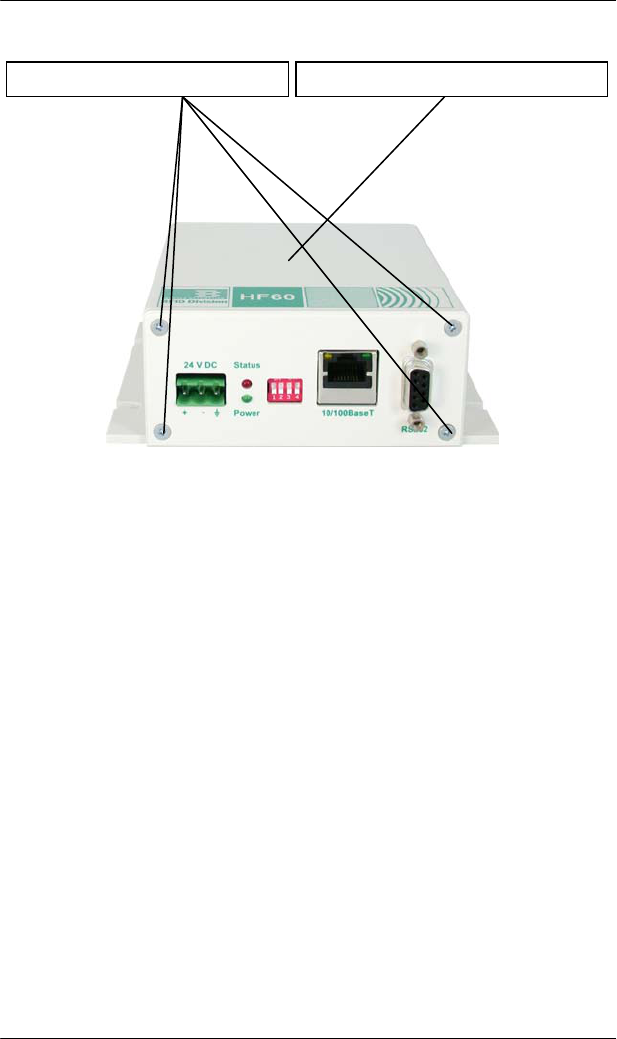
SERVICE AND ERROR HANDLING 6
143
HF80 Transponder Reader – HSMS, Release 1.3
Open the device:
6.5 Reader Does Not Respond
1 Check if the interface connection cable is undamaged and
correctly connected to both reader and host.
2 Check the status as indicated by the LED’s (see page 142).
3 If you are not sure about the active host interface then test both
interfaces (RS232 and Ethernet).
4 Contact BROOKS for the firmware file and the Firmware
Update Software to update the firmware of the reader.
If these measures do not solve the problem, contact the manufacturer.
6.6 Reset
In the case of software errors, a power reset can be carried out by
stopping and restarting the power supply.
After the reset, the reader implements a self-test. While the self-test is
running, the status LED is ON. If the test was successful, all LED’s
except the power LED, are extinguished.
2. Remove the upper part of the housing 1. Loose the 4 screws on the housing

6 SERVICE AND ERROR HANDLING
144 HF80 Transponder Reader – HSMS, Release 1.3
6.7 Power Cut
After a power cut, the reader carries out a reset with self-test. While
the self-test is running, the status LED is ON. If the test was
successful, all LED’s, except for the power LED, are extinguished.
6.8 Software Releases
Release Date Version Description
12/2008 RS2P15 First Version. (Fineversion 150)
01/2009 RS2P20
Fineversion 200. Data item DATASEGB
and DATAB for messages S18F5/F6,
S18F7/F8, S18F67/F68, S18F69/F70
implemented to address the tag data byte by
byte.
Polling functionality disabled.
02/2009 RS2P21
Messages S18F87 and S18F89 Æ Read
Write Counter without and with UID.
6.9 Customer Service
BROOKS Automation (Germany) GmbH
RFID Division
Gartenstraße 19
D-95490 Mistelgau
Germany
Tel: +49 9279 991 910
Fax: +49 9279 991 900
E-mail: rfid.support@brooks.com
24 hour technical support hotline (Brooks): +1 978 262 2900

DEINSTALLATION AND STORAGE 7
145
HF80 Transponder Reader – HSMS, Release 1.3
7 DEINSTALLATION AND STORAGE
7.1 Deinstallation
1 Disconnect the power supply.
2 Disconnect all cables.
3 Loosen and remove the mounting screws.
4 Remove the reader from its installation surface.
7.2 Storage
Store the reader and its components in a clean and dry environment
with the power supply disconnected. Make sure the contacts remain
clean. Observe the necessary storage conditions (for technical data, see
page 19).

8 TRANSPORTATION AND DISPOSAL
146 HF80 Transponder Reader – HSMS, Release 1.3
8 TRANSPORTATION AND DISPOSAL
8.1 Transportation
For transportation purposes such as mailing, use a firm cardboard box.
Use adequate padding material to protect the device on all sides.
8.2 Disposal
The transponder reader and its components consist of different
materials. Dispose of these materials separately in accordance with the
relevant legislation in your country. Do not throw them away with
everyday household trash.
Separate the interior electronic components from the case. Dispose of
The case as plastic trash
The electronic components, antennas and cables as electronic
trash.

ACCESSORIES 9
147
HF80 Transponder Reader – HSMS, Release 1.3
9 ACCESSORIES
9.1 Device Options
Type Part-No.
Transponder Reader with 5 antenna ports
and Ethernet- and serial interface, no
IO’s
THG-E3SM-2O00-T5-0000
Transponder Reader with 5 antenna ports
and Ethernet- and serial interface, 1
Input and 2 Outputs per antenna head
THG-E3SM-2O00-T5-00E2
Transponder Reader with 5 antenna ports
and Ethernet interface, no IO’s THG-T3SM-2O00-T5-0000
Transponder Reader with 5 antenna ports
and Ethernet interface, 1 Input and 2
Outputs per antenna head
THG-T3SM-2O00-T5-00E2
Transponder Reader with 1 antenna port
and Ethernet- and serial interface, no
IO’s
THG-E3SM-2O00-T1-0000
Transponder Reader with 1 antenna port
and Ethernet- and serial interface, 1
Input and 2 Outputs per antenna head
THG-E3SM-2O00-T1-00E2
Transponder Reader with 1 antenna port
and Ethernet interface, no IO’s THG-T3SM-2O00-T1-0000
Transponder Reader with 1 antenna port
and Ethernet interface, 1 Input and 2
Outputs per antenna head
THG-T3SM-2O00-T1-00E2
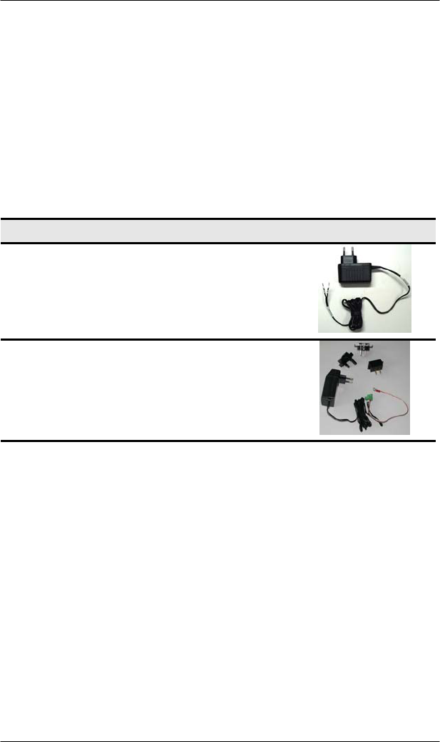
9 ACCESSORIES
148 HF80 Transponder Reader – HSMS, Release 1.3
9.2 Antennas
Different antenna types are available on request!
9.2.1 Reading and Writing Ranges
The reading and writing range depends on the type of antenna, the type
of tag, the power level at antenna and the installation environment
(metal close to antenna and/or tag).
9.3 Power Supply
Type Part-No. Picture
Power Supply 24VDC
EURO-Plug SVG 0,33 HF
Power Supply 24VDC
Adapters for different
countries
SVG0,6HF-UNI