Brooks Automation LF60C RFID Reader User Manual RFID Reader LF60C SoliD
Brooks Automation (Germany) GmbH RFID Division RFID Reader RFID Reader LF60C SoliD
UserManual.wiki
>
Brooks Automation
>
LF60C User Manual
User Manual
Navigation menu
Upload a User Manual
Namespaces
Wiki Guide
HTML
PDF
Info
Views
User Manual
Discussion / Help
Navigation

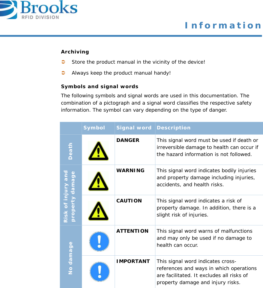
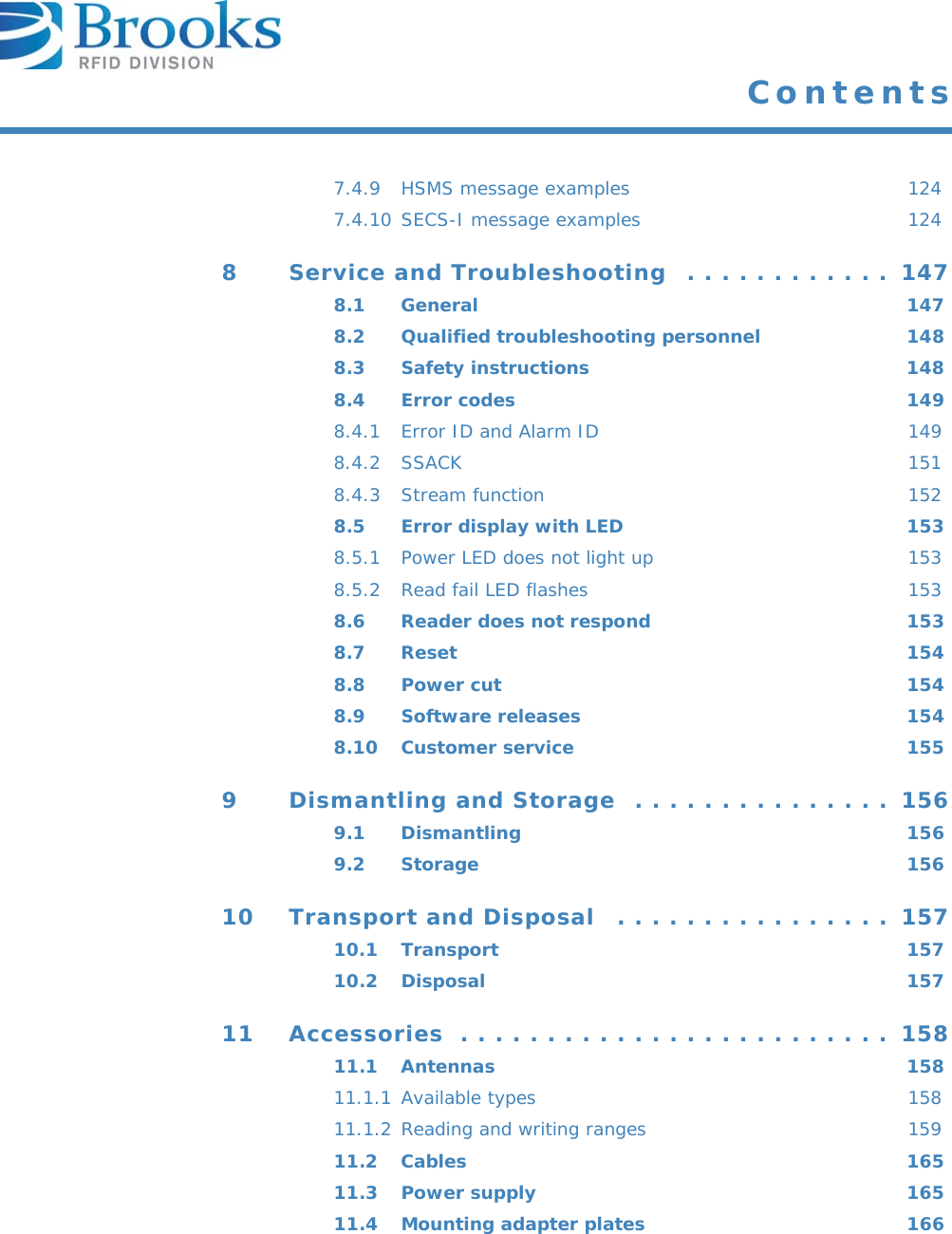


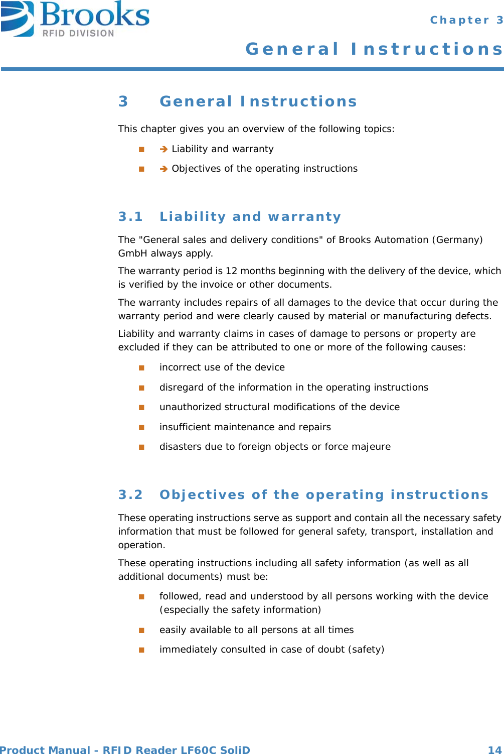


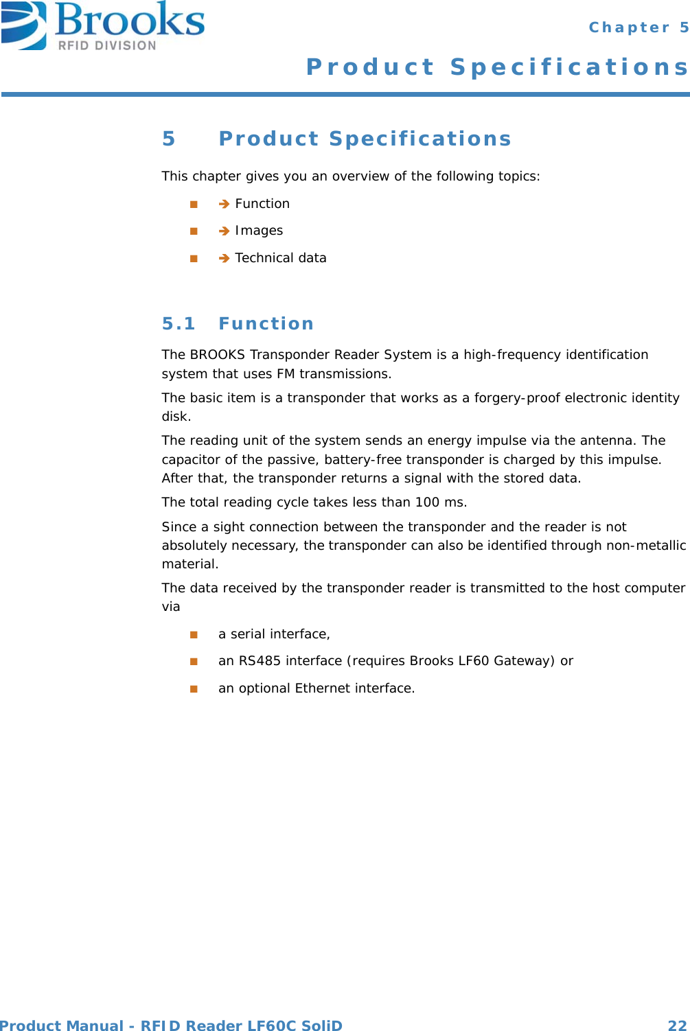


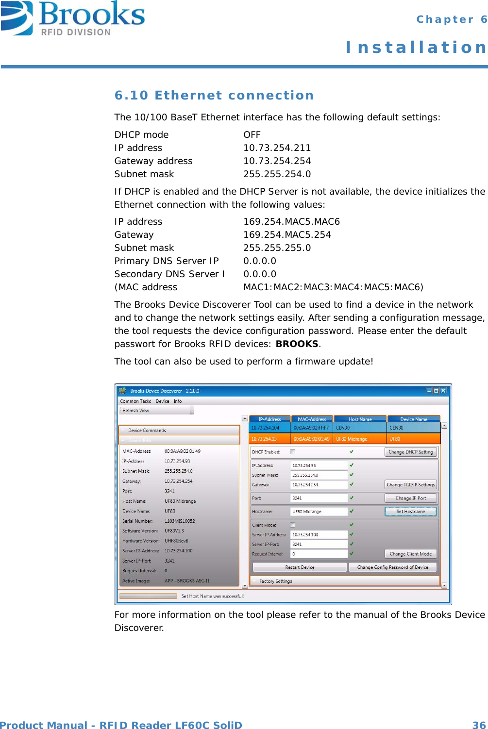
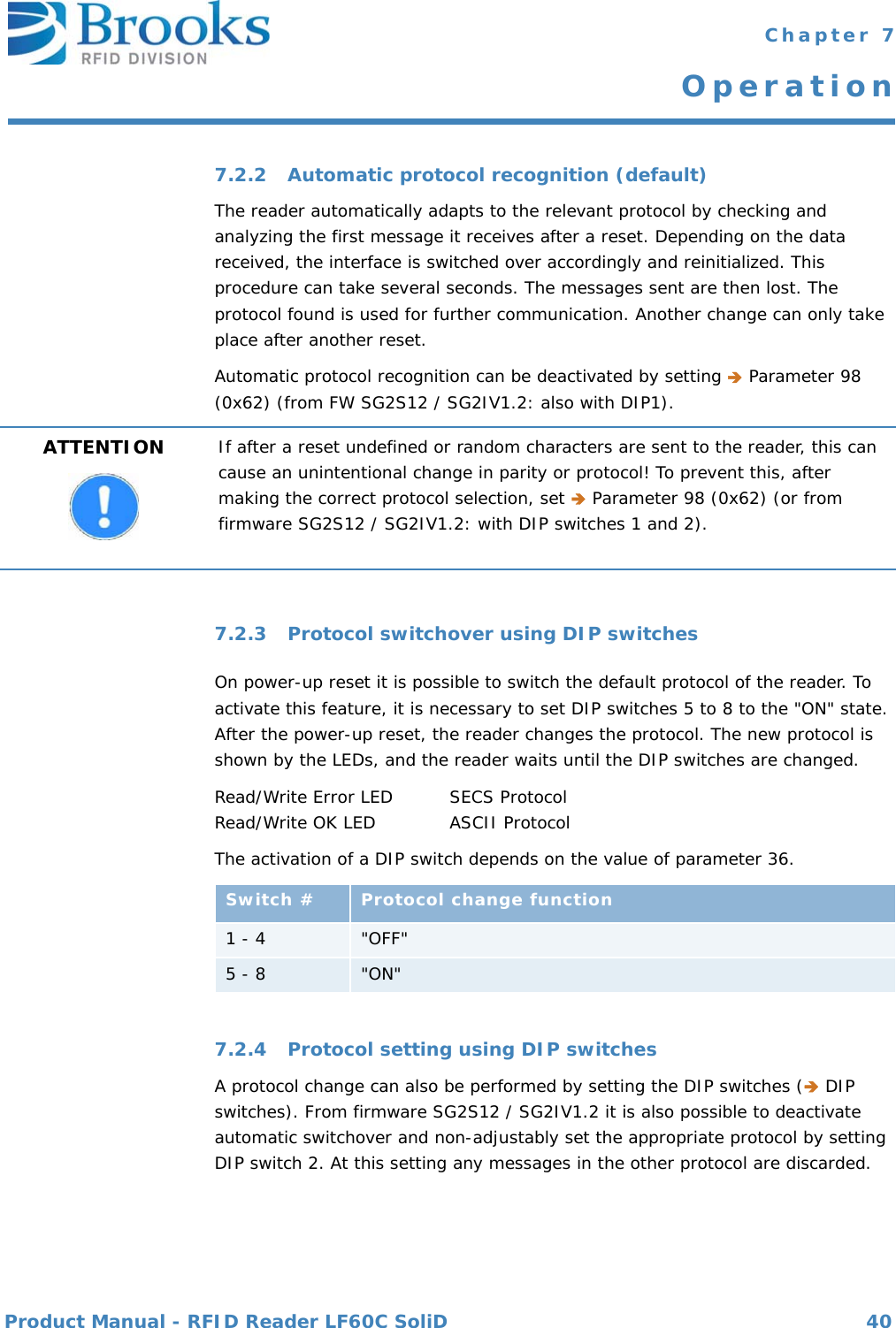
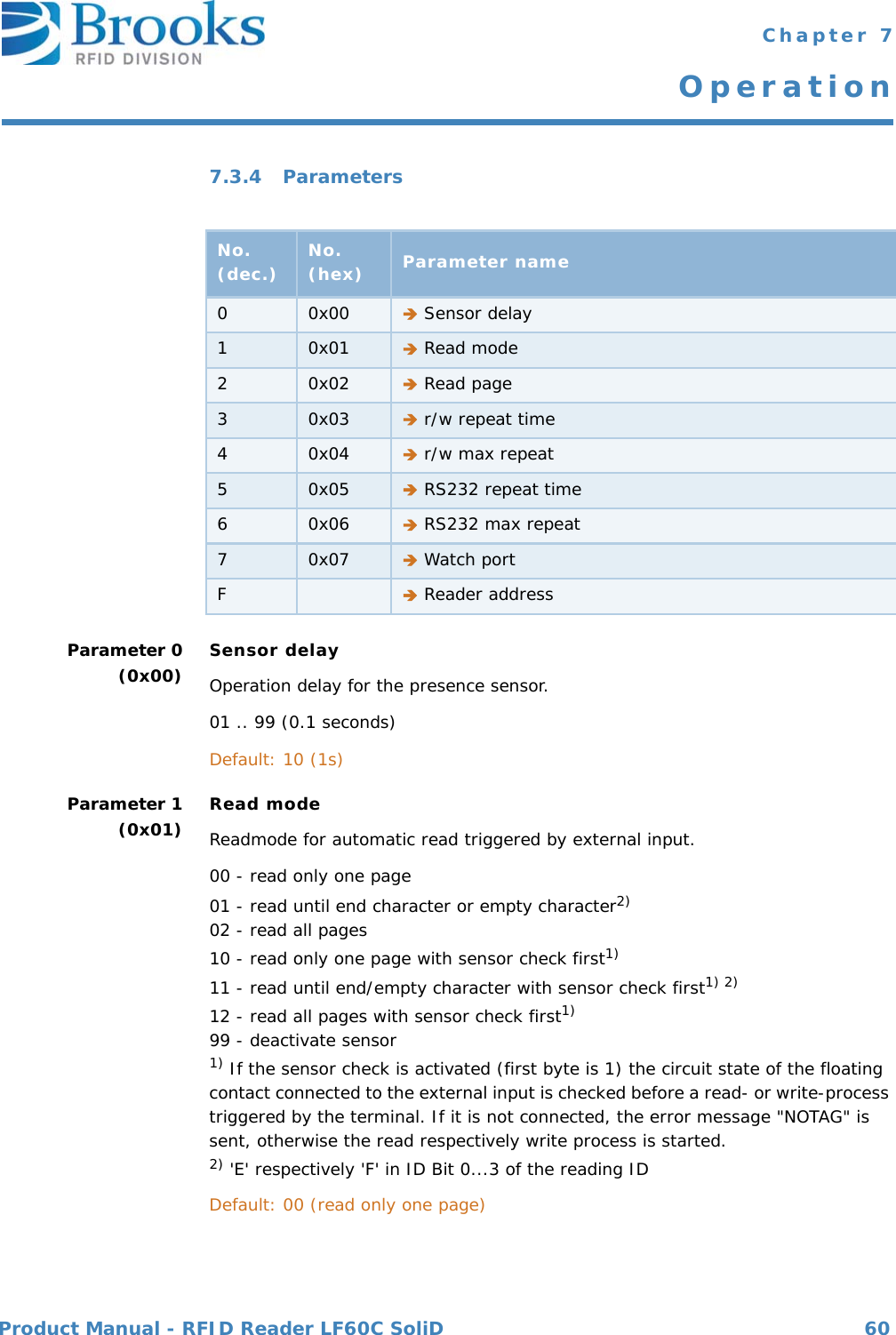
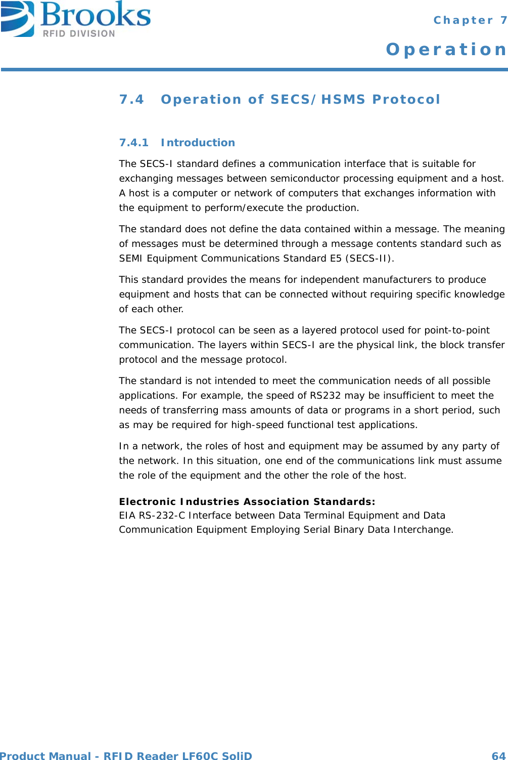
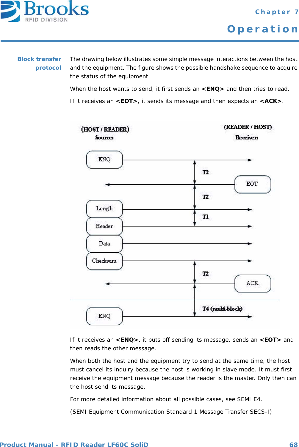
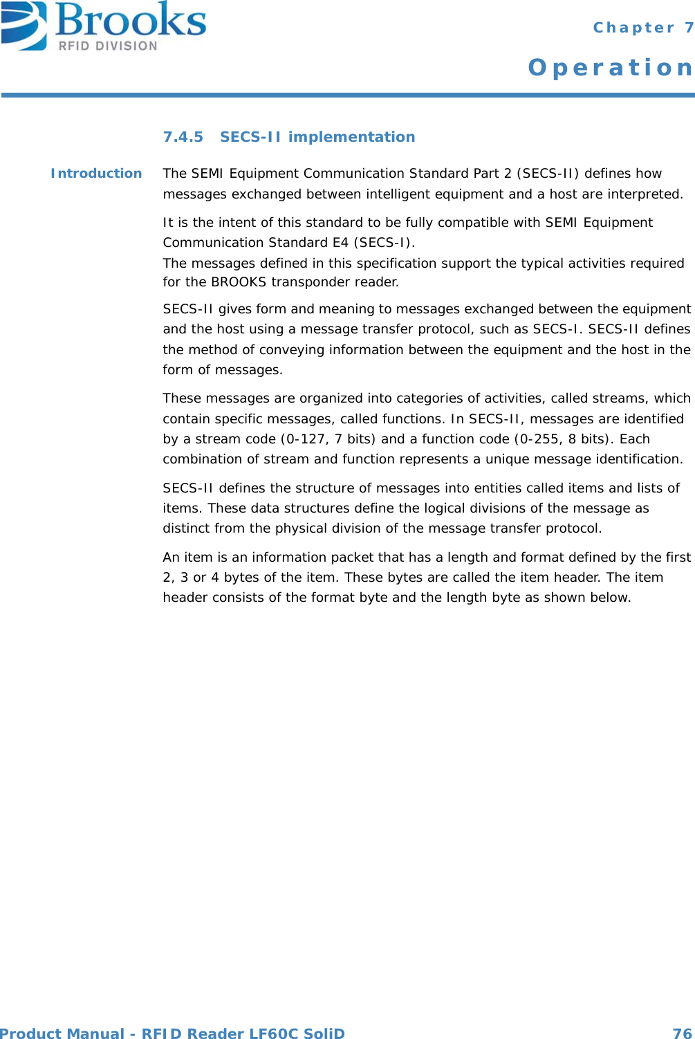
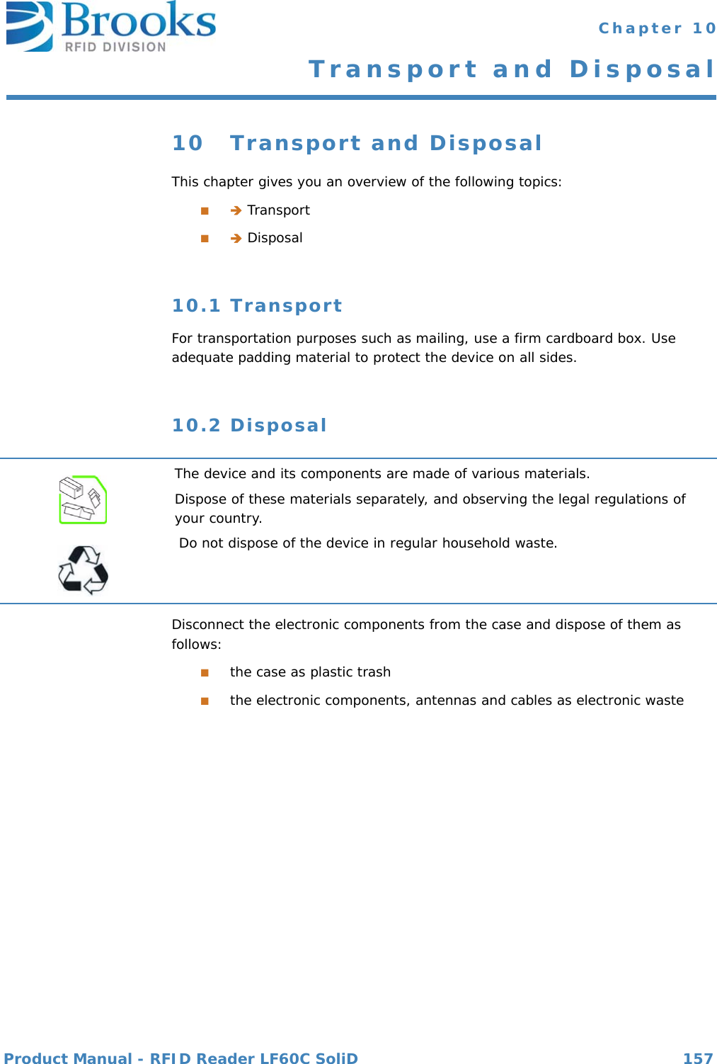
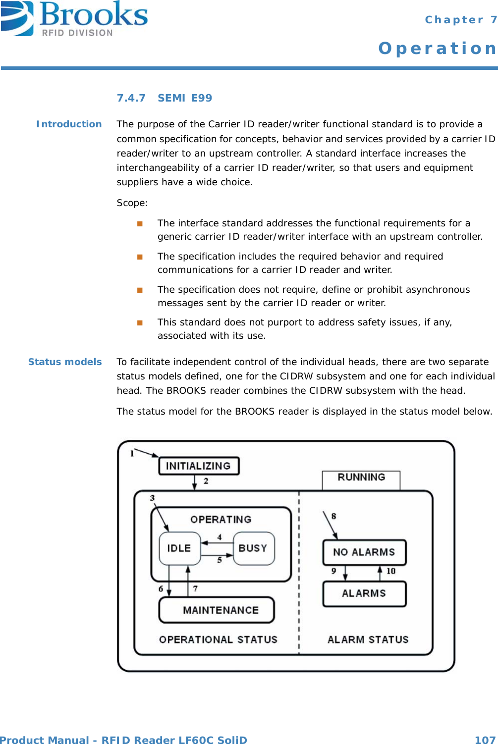
![Product Manual - RFID Reader LF60C SoliD 78 Chapter 7OperationData items The formats represent arrays of types: <type>[number of elements], whereby <type> is one of the following:Oct- code Hex-code Format Meaning Example00 01 List List element with the number of the "Length" data elements<L2> <A "Hello"> <B 0x00>11 25 Boolean 1-byte Booleanfalse = 00true = 01 <Boolean1 0x00>10 21 Binary Byte sequenceof the length "Length" <B1 0x01>20 41 ASCII Printable ASCII characters <A "Hello">31 65 I1 1-byte signed integer <I1 123>32 69 I2 2-byte signed integer <I2 -12345>34 71 I4 4-byte signed integer <I4 2147483647>30 61 I8 8-byte signed integer <I8 931372980293834>51 A5 U1 1-byte unsigned integer <U1 0>52 A9 U2 2-byte unsigned integer <U2 #empty>54 B1 U4 4-byte unsigned integer <U4 429489725>50 A1 U8 8-byte unsigned integer <U8 763468676756767>40 91 F8 8-byte floating point <F8 1.223 e204>44 81 F4 4-byte floating point <F4 -1.23 >](https://usermanual.wiki/Brooks-Automation/LF60C/User-Guide-2012591-Page-78.png)
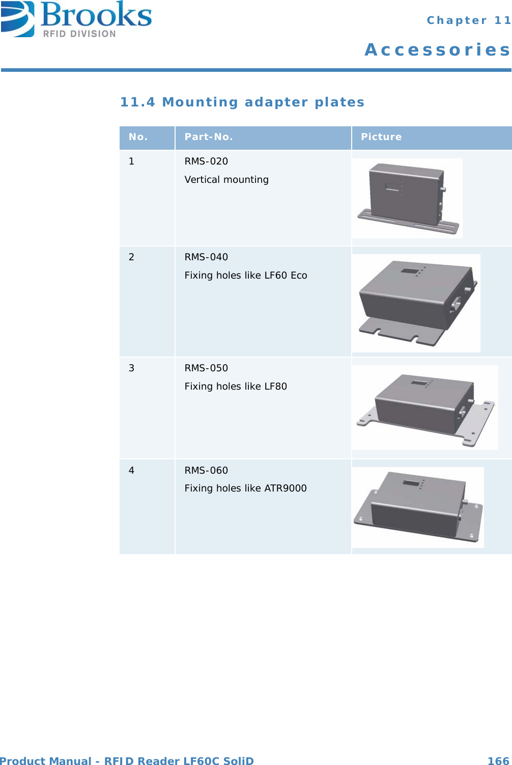
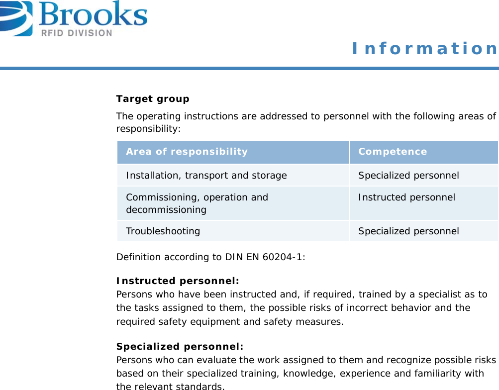
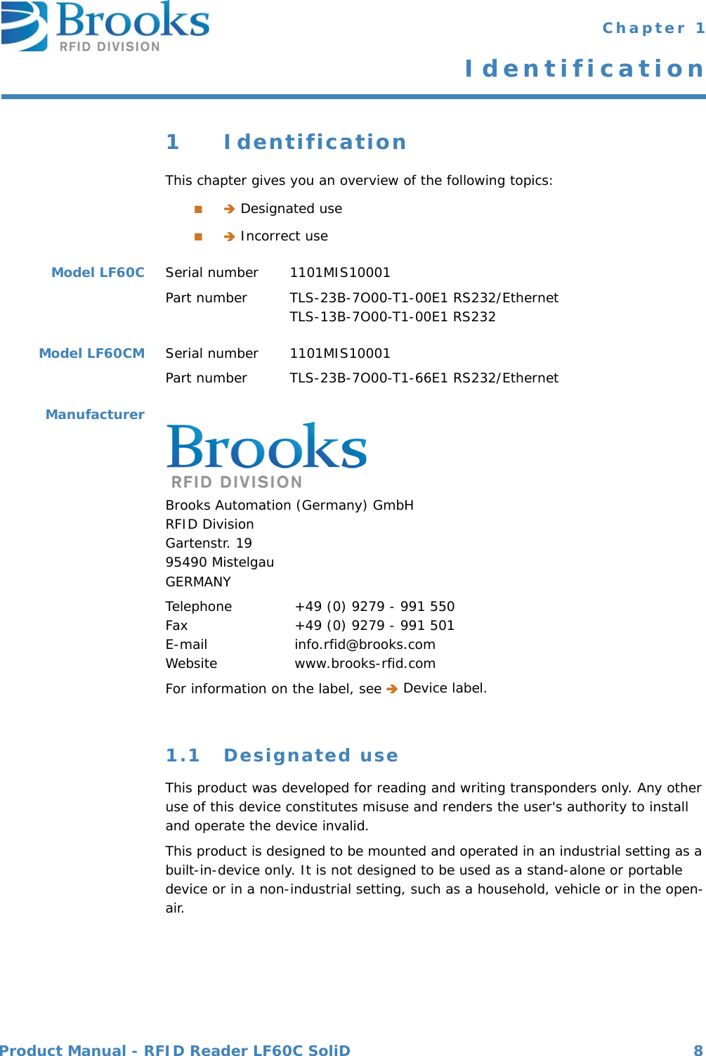
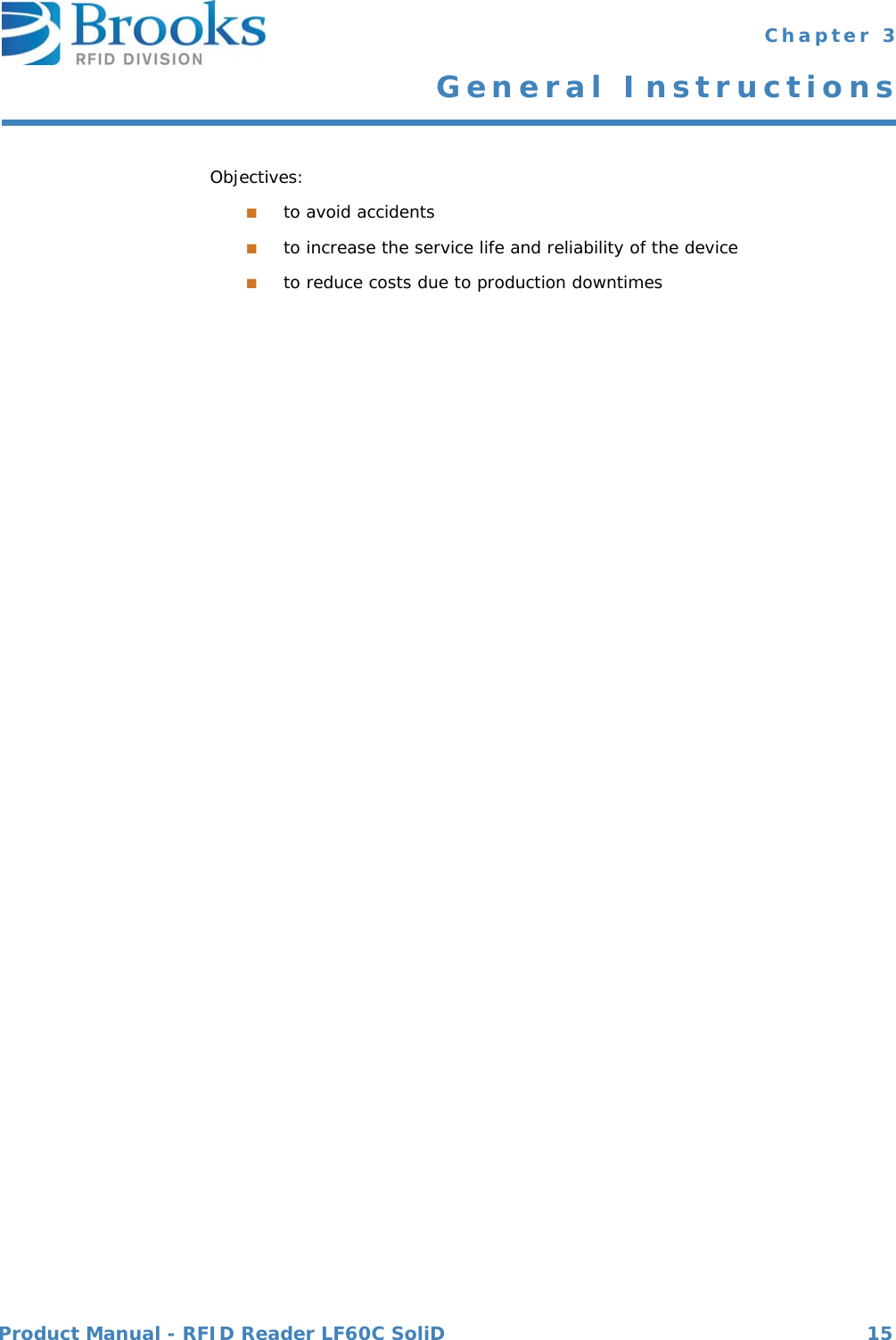
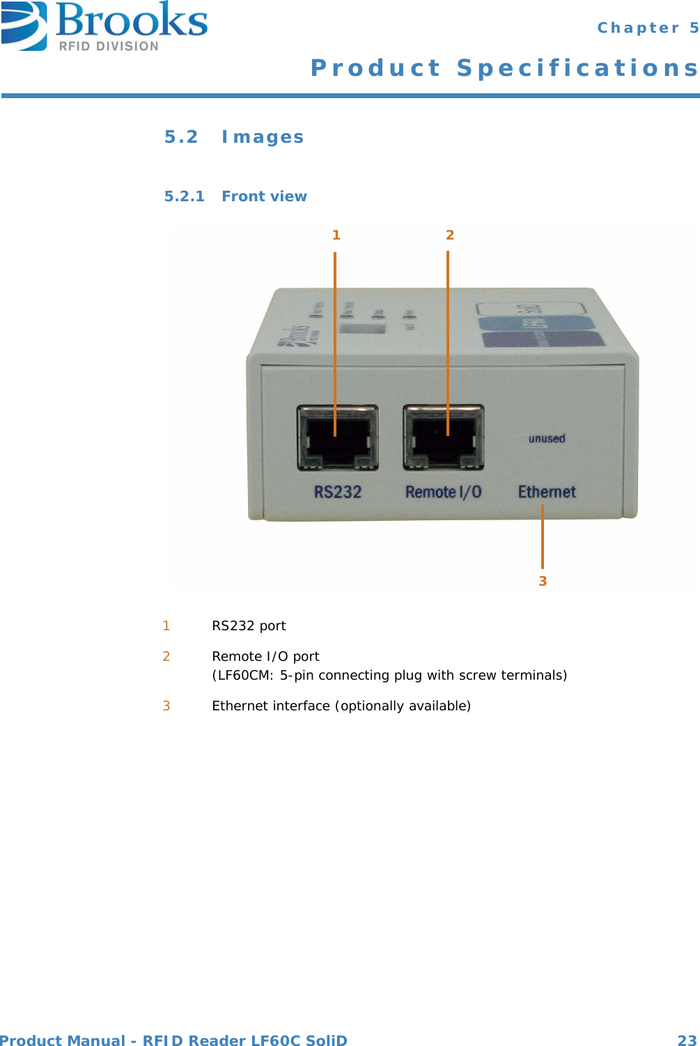
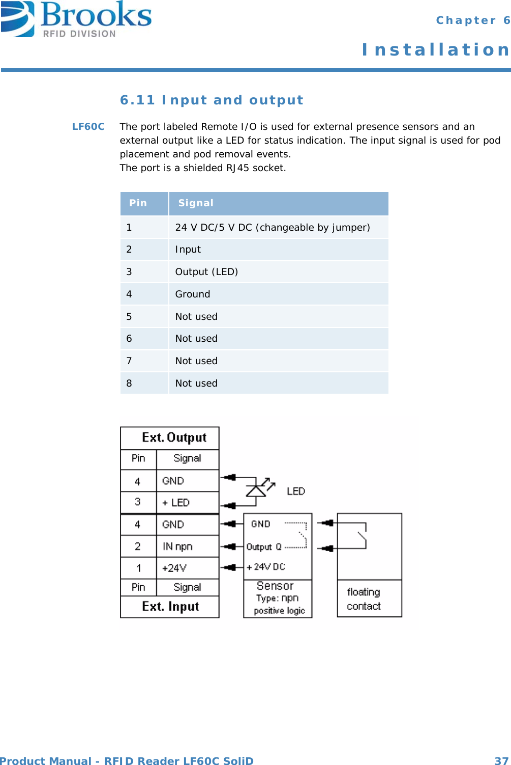
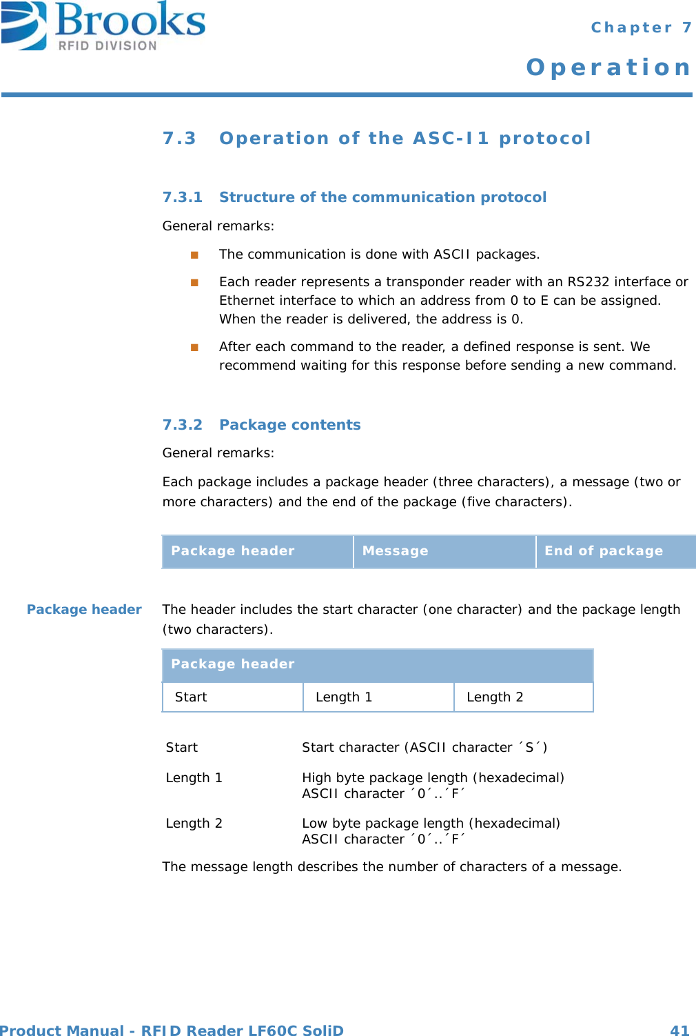
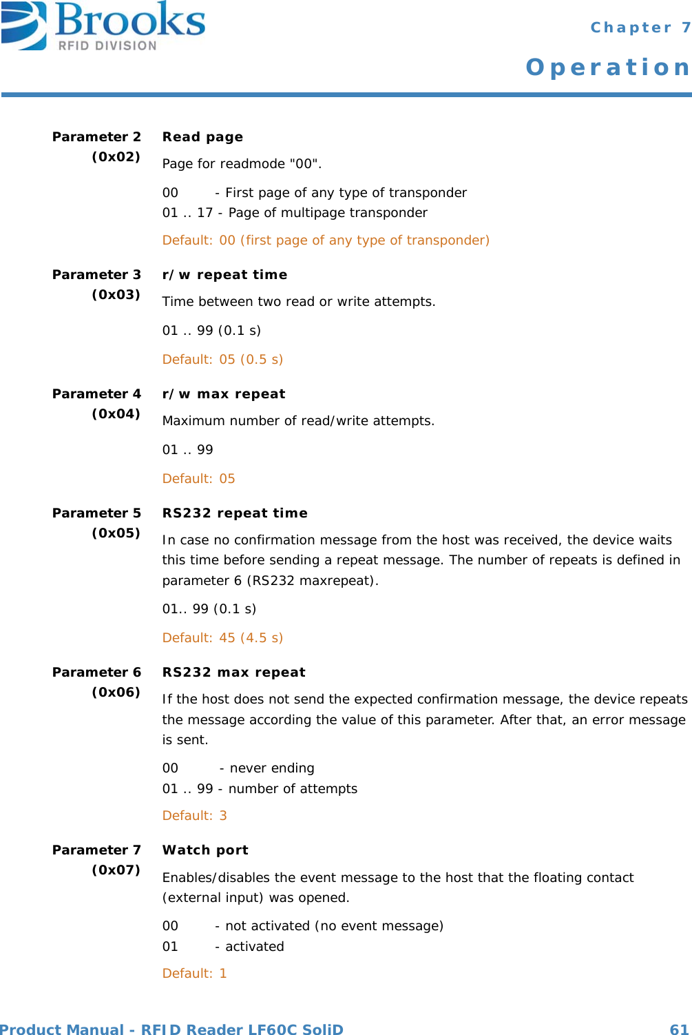
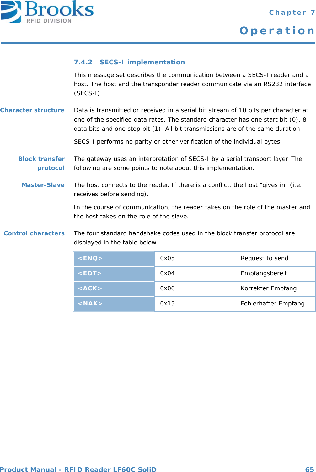
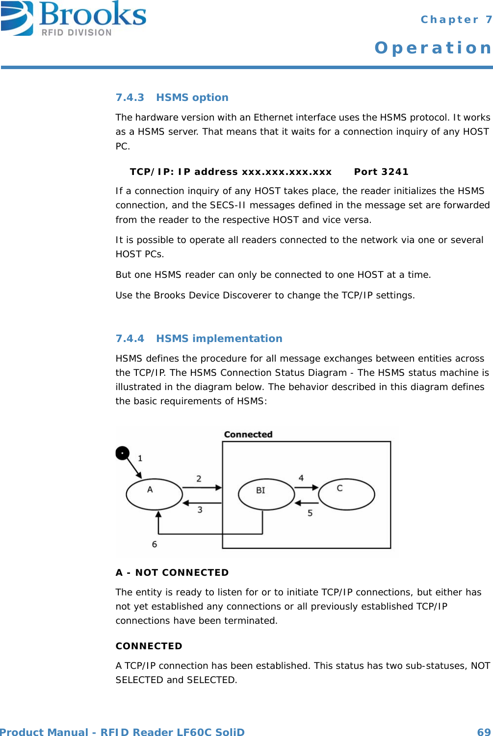
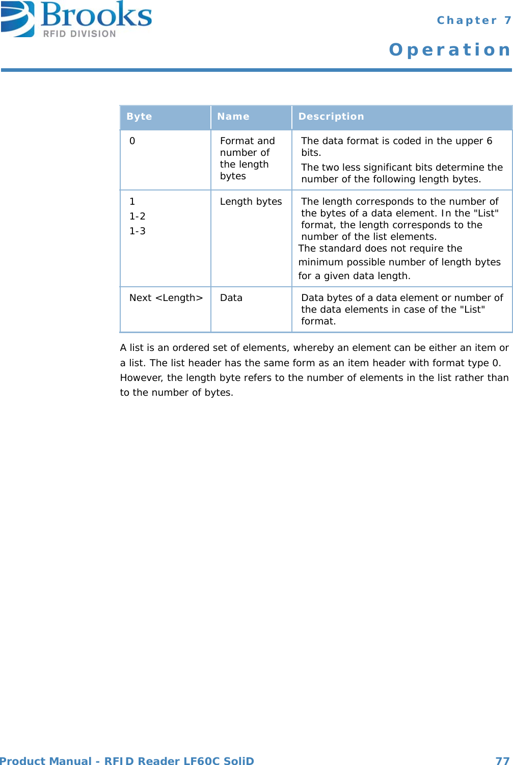
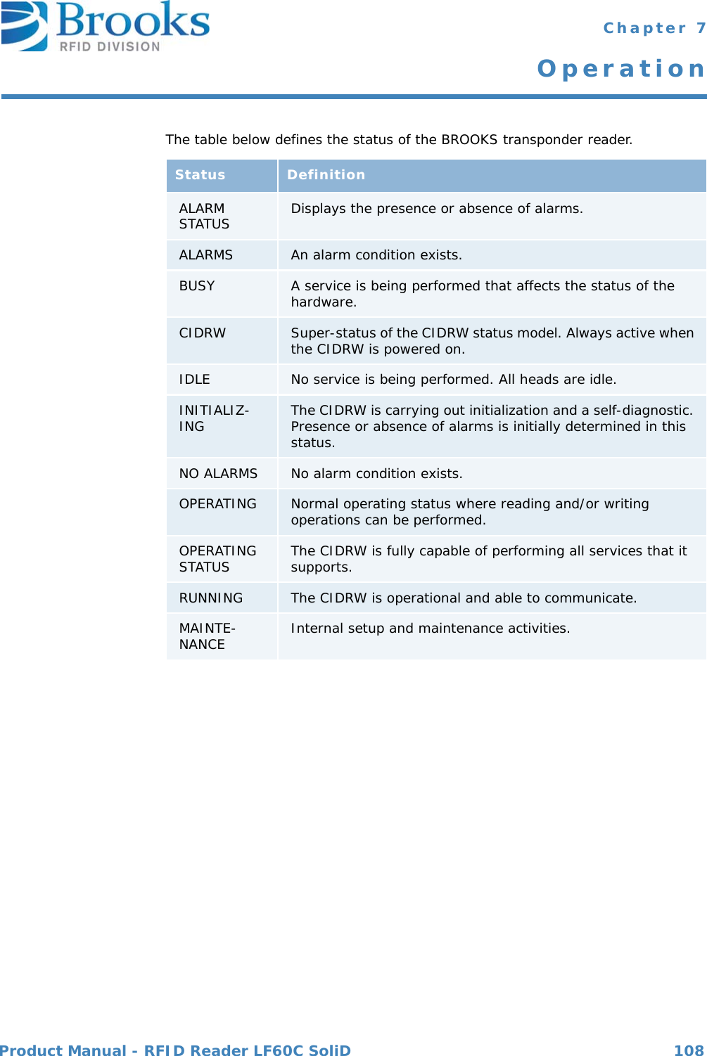
![Product Manual - RFID Reader LF60C SoliD 81 Chapter 7OperationData itemdictionary This section defines the data items used in the standard SECS-II messages described in the section "Message details".Syntax:Acknowledge code0 : Sensor 0 was the initiator>0 : Error, not acceptedWhere used S3F6, S3F8Acknowledge code0 : No error>0 : Error, not acceptedWhere used S5F2Name A unique name for this data item. This name is used in the message definitions.Format The permitted item format code which can be used for this standard data item.Item format codes are shown in hex and octal, as described in the chapter Data items.The notification "3()" indicates any of the signed integer formats (30, 31, 32, 34).Description A description of the data item, with the meanings of specific values.Where used The standard messages in which the data item appears.ACKC3 Format: B[1]ACKC5 Format: B[1]](https://usermanual.wiki/Brooks-Automation/LF60C/User-Guide-2012591-Page-81.png)
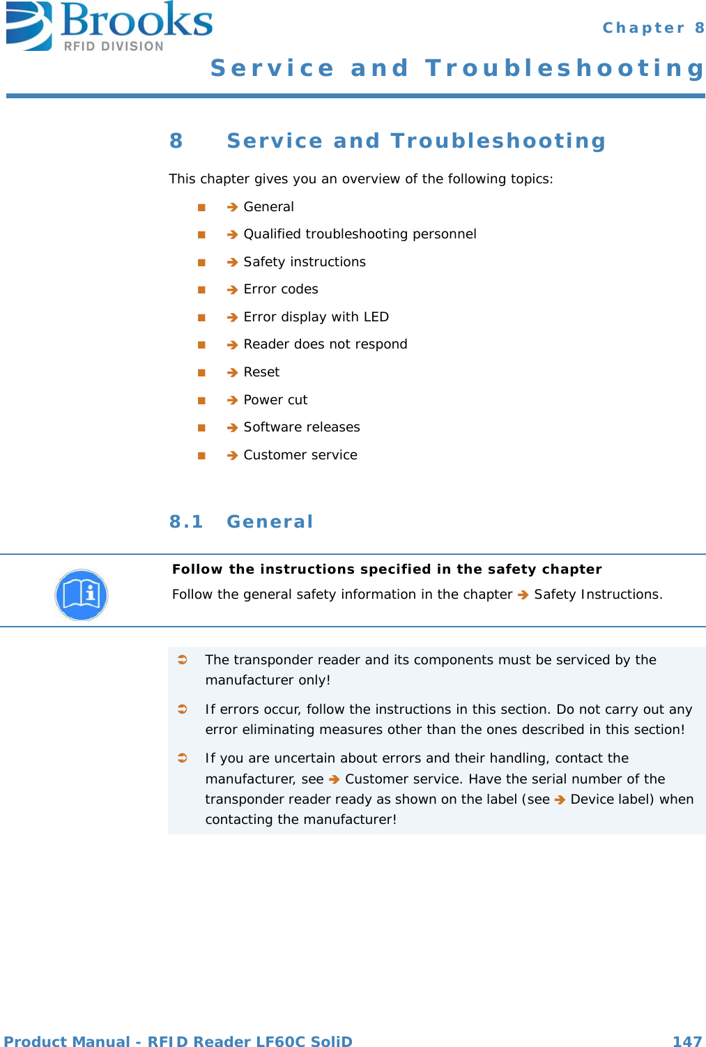
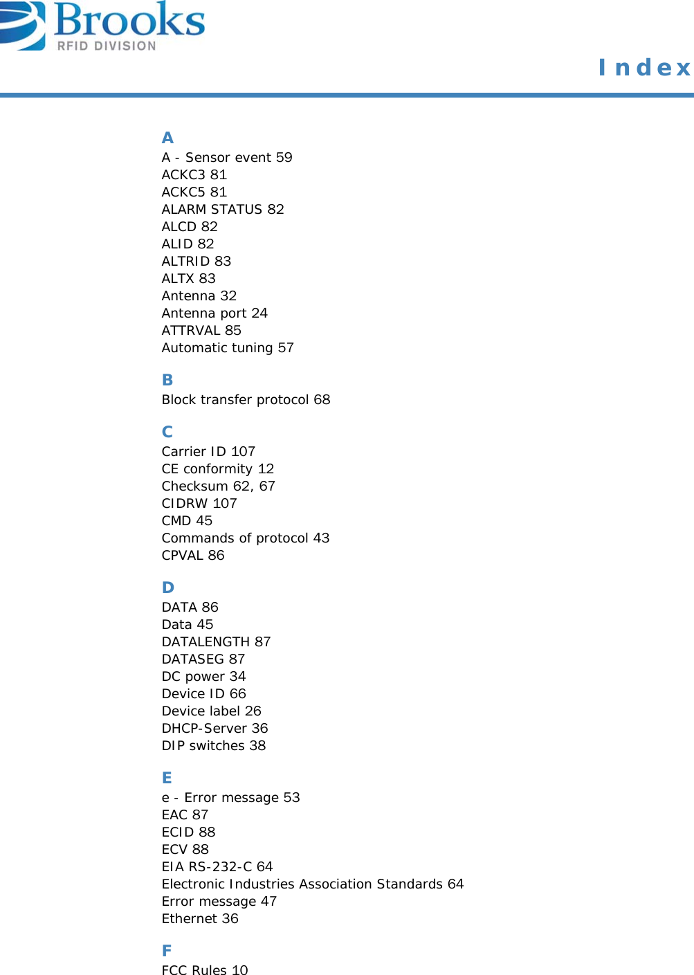
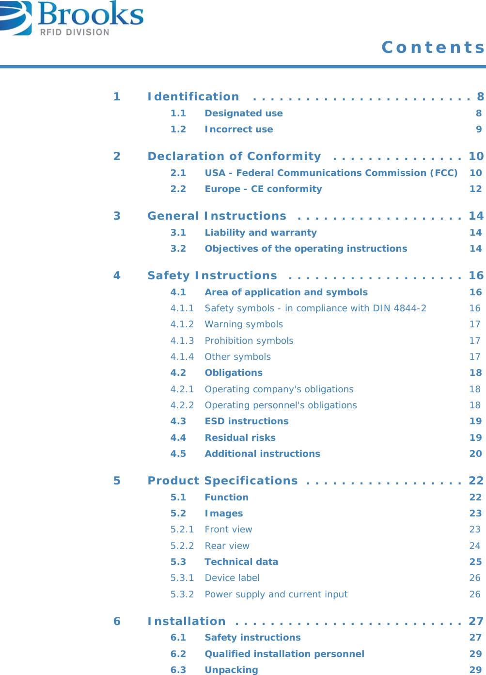
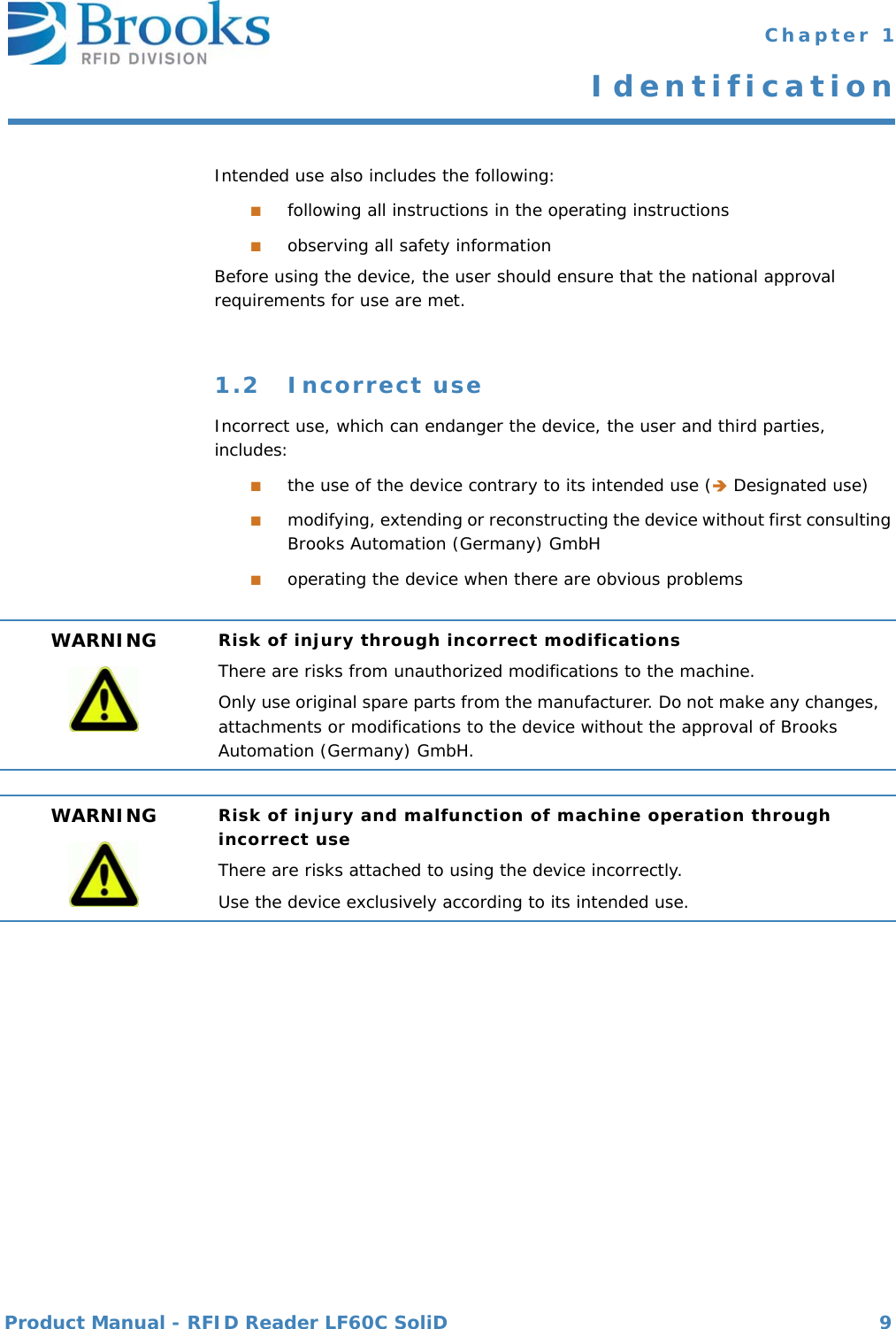
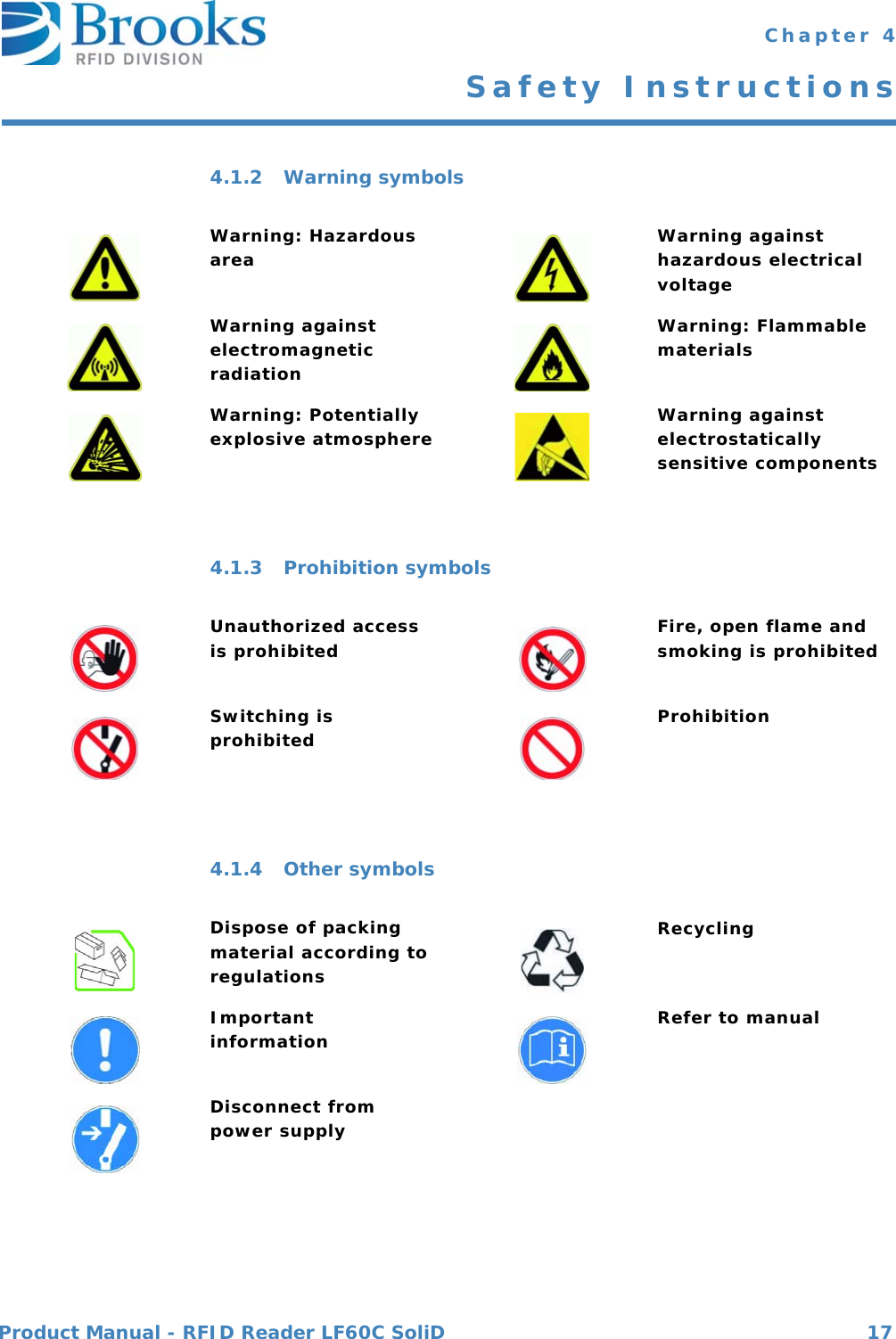
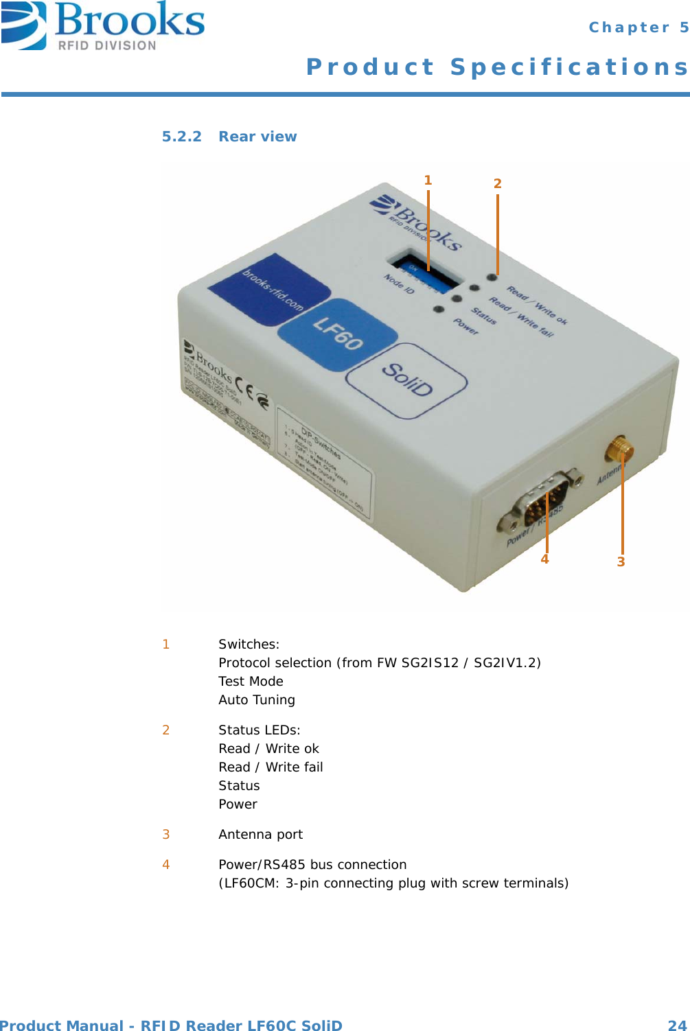
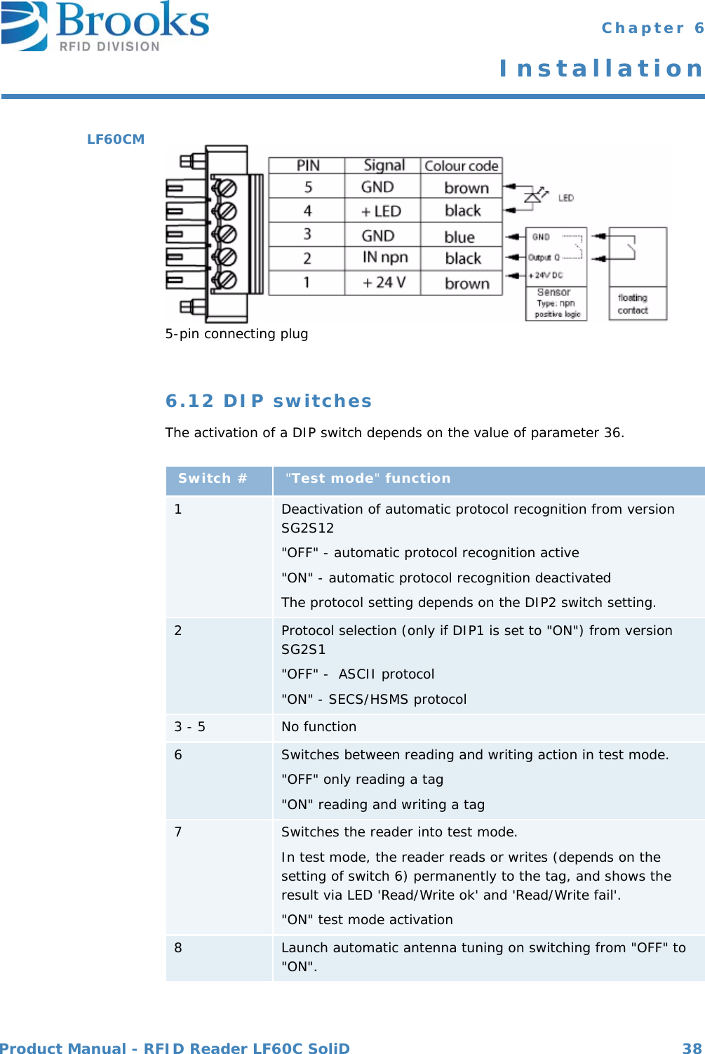
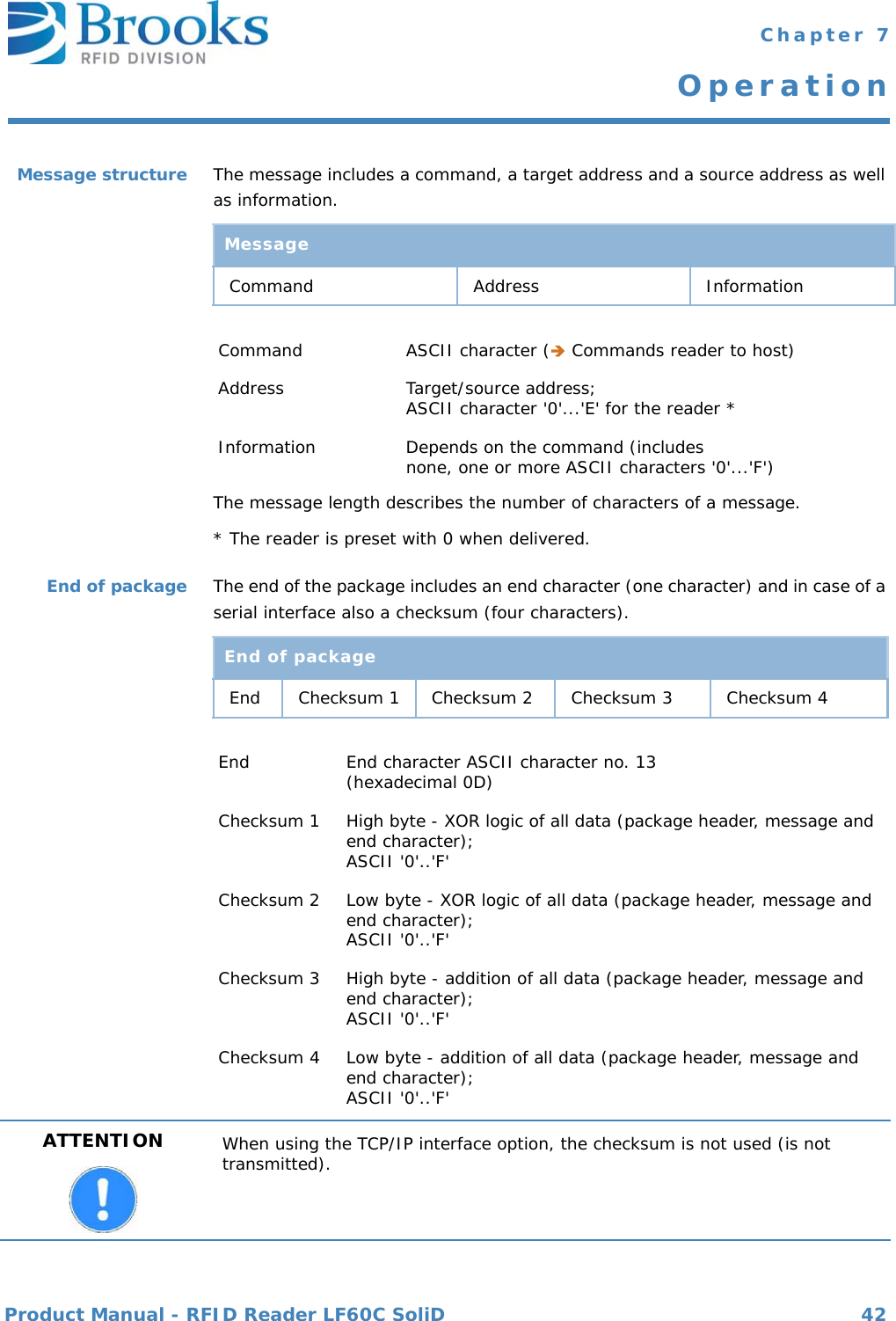
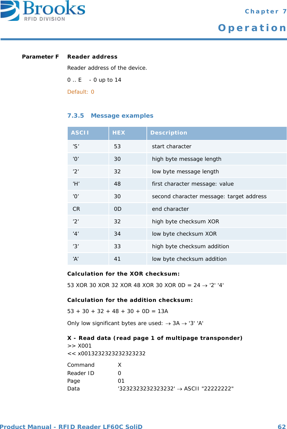
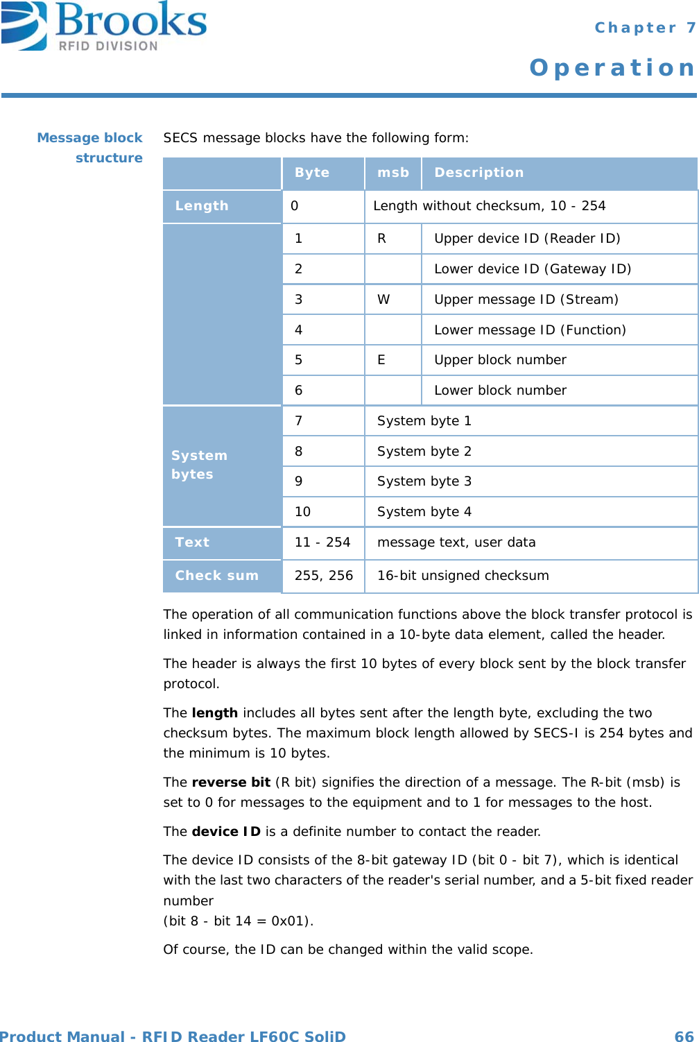
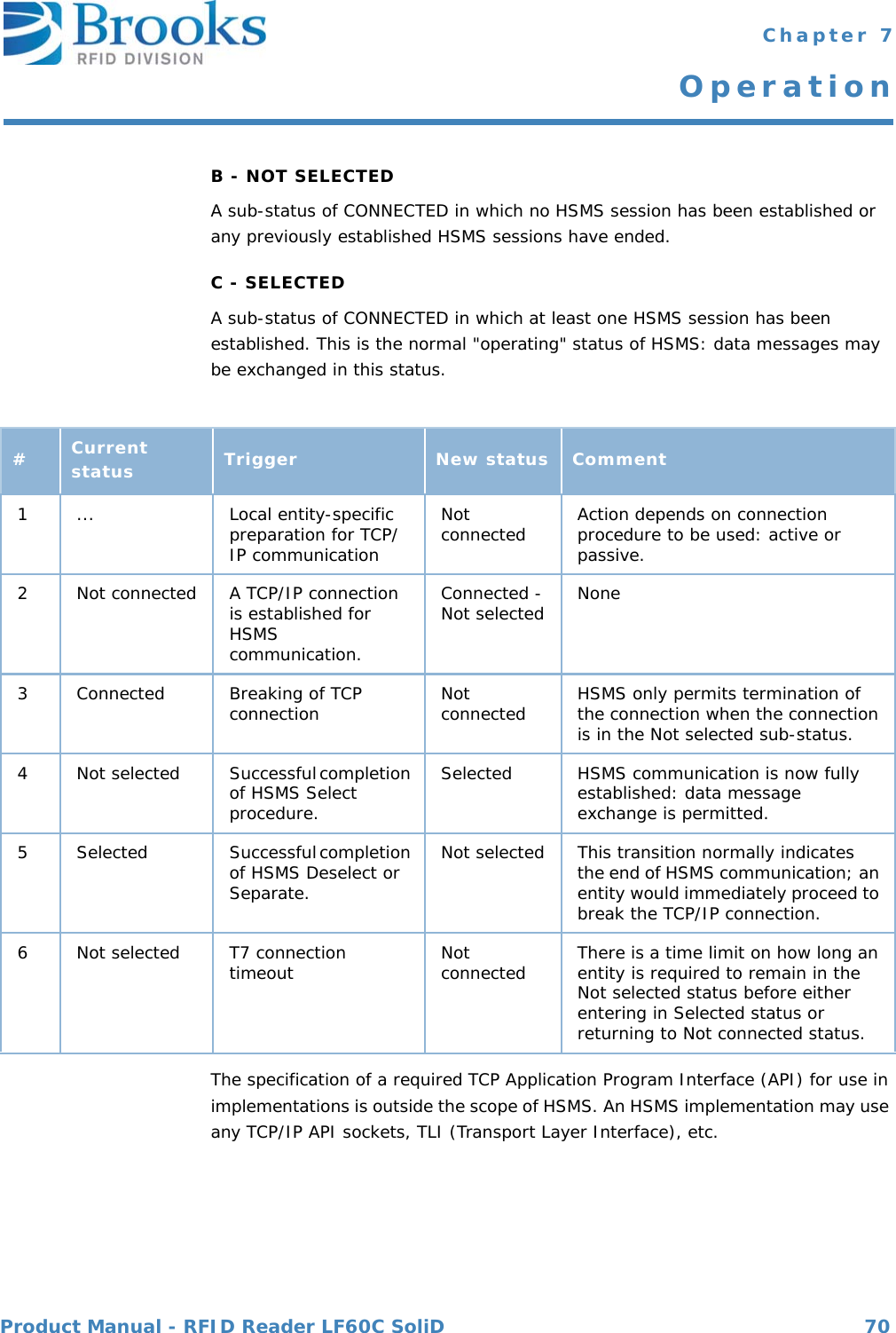
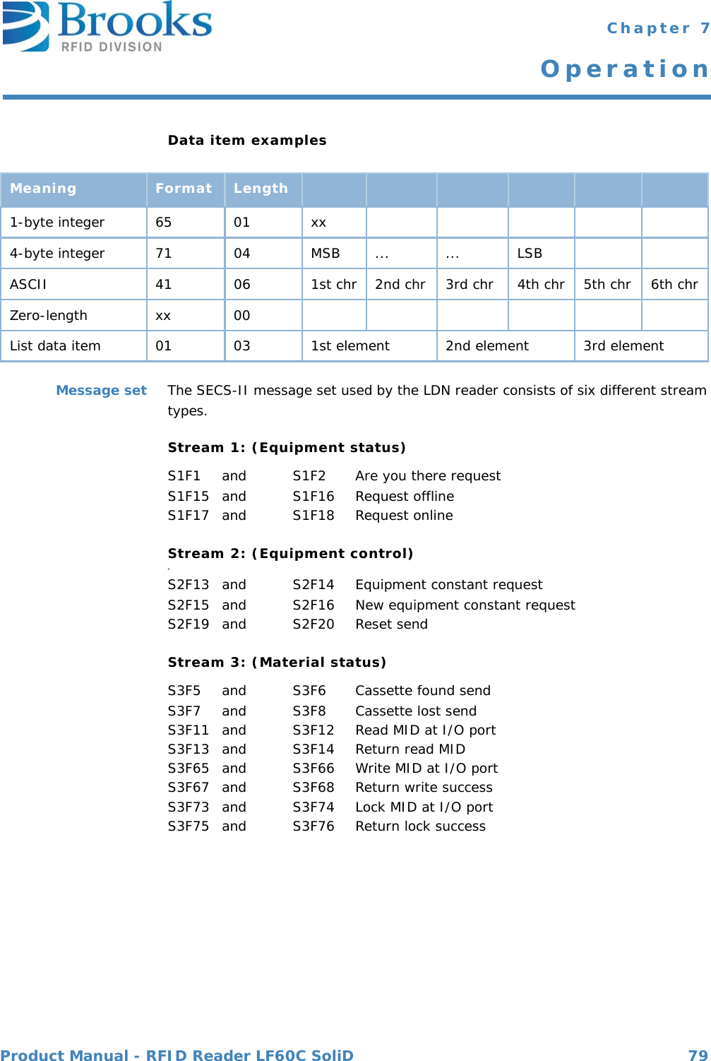
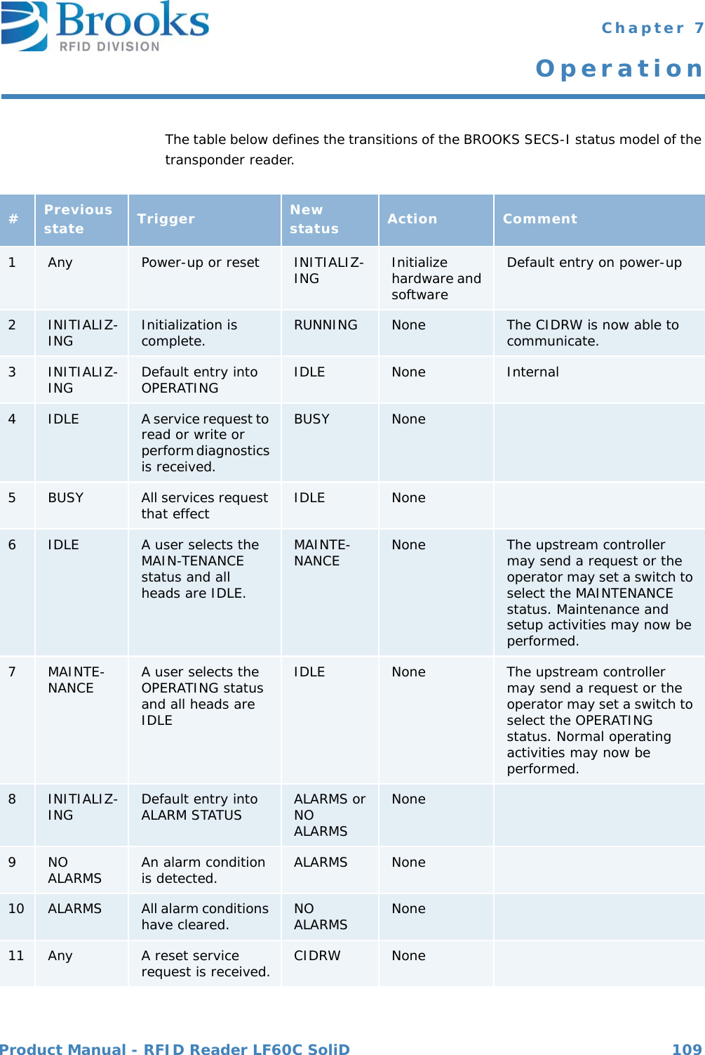
![Product Manual - RFID Reader LF60C SoliD 82 Chapter 7OperationDescription The value of the alarm status refers to the last reading process. If a read or write error occurs, the alarm status is set.A successful read or write resets the alarm status. When leaving maintenance mode, the alarm status is alsodeleted.0 ... No alarm1 ... AlarmWhere used S18F13Alarm code byteOnly the occurrence of an error is reported. Errors are not generally reset.bit 8 = 1 Alarm is setWhere used S5F1Alarm identifier0 No error1 Auto read failed, the reader is engaged 2 External read failed, the reader is engaged 3 External write failed, the reader is engaged 4 No tag could be recognized when the sensor was covered or the carrier had been removed prematurely (sensor uncovered)5 Invalid command or parameter detected6 Unknown error7Reserved8 Parity error or checksum error detected9 Unexpected confirmation was sent10 Locked page could not be written11 Reserved12 Incorrect type of transponder13 External read or write failed because the sensor is not covered14 Reserved15 Reserved16 ReservedFor more information on error codes and the corresponding correcting actions please refer to Error codes.Where used S5F1ALARM STATUS Format: A[1]ALCD Format: B[1]ALID Format: B[1]](https://usermanual.wiki/Brooks-Automation/LF60C/User-Guide-2012591-Page-82.png)
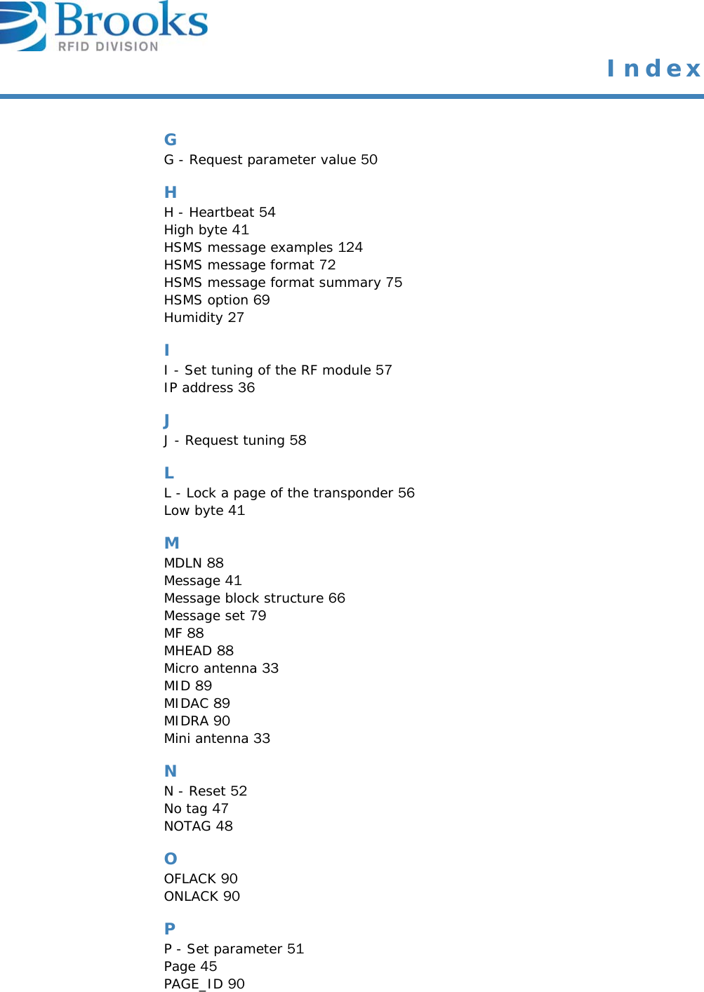
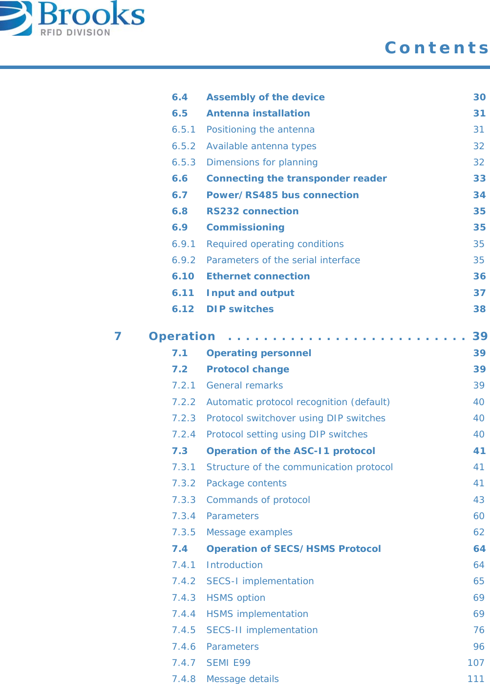
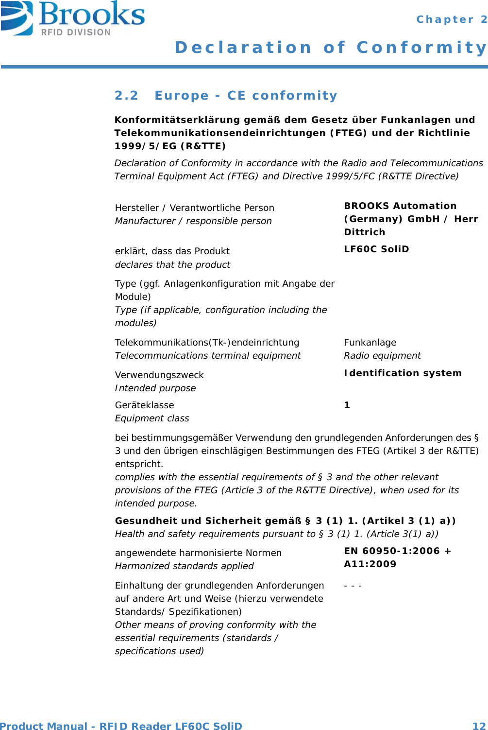
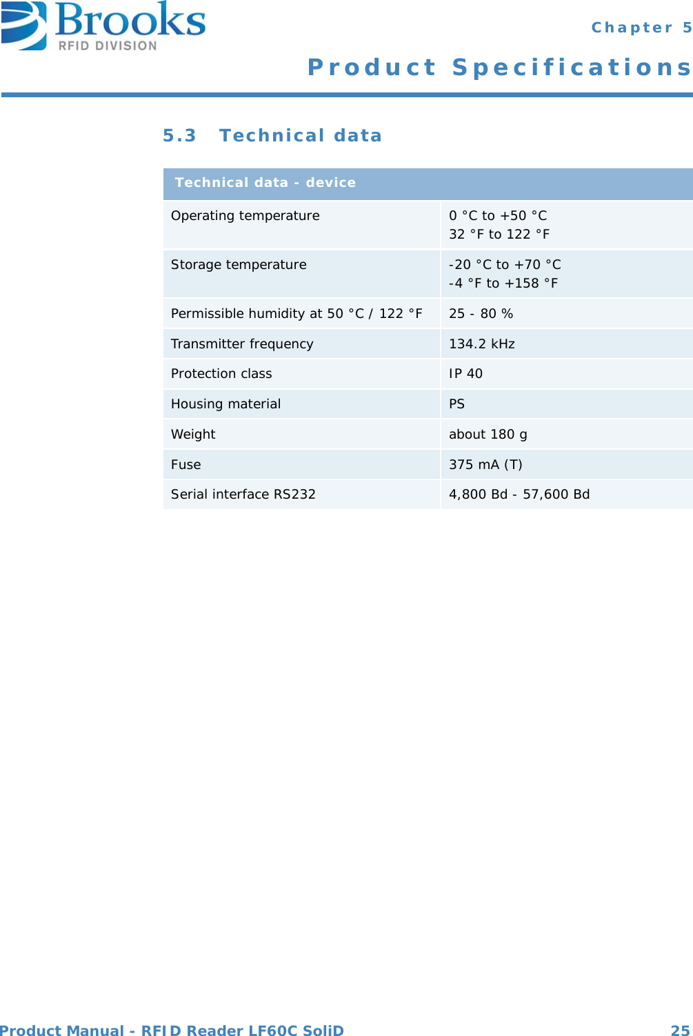
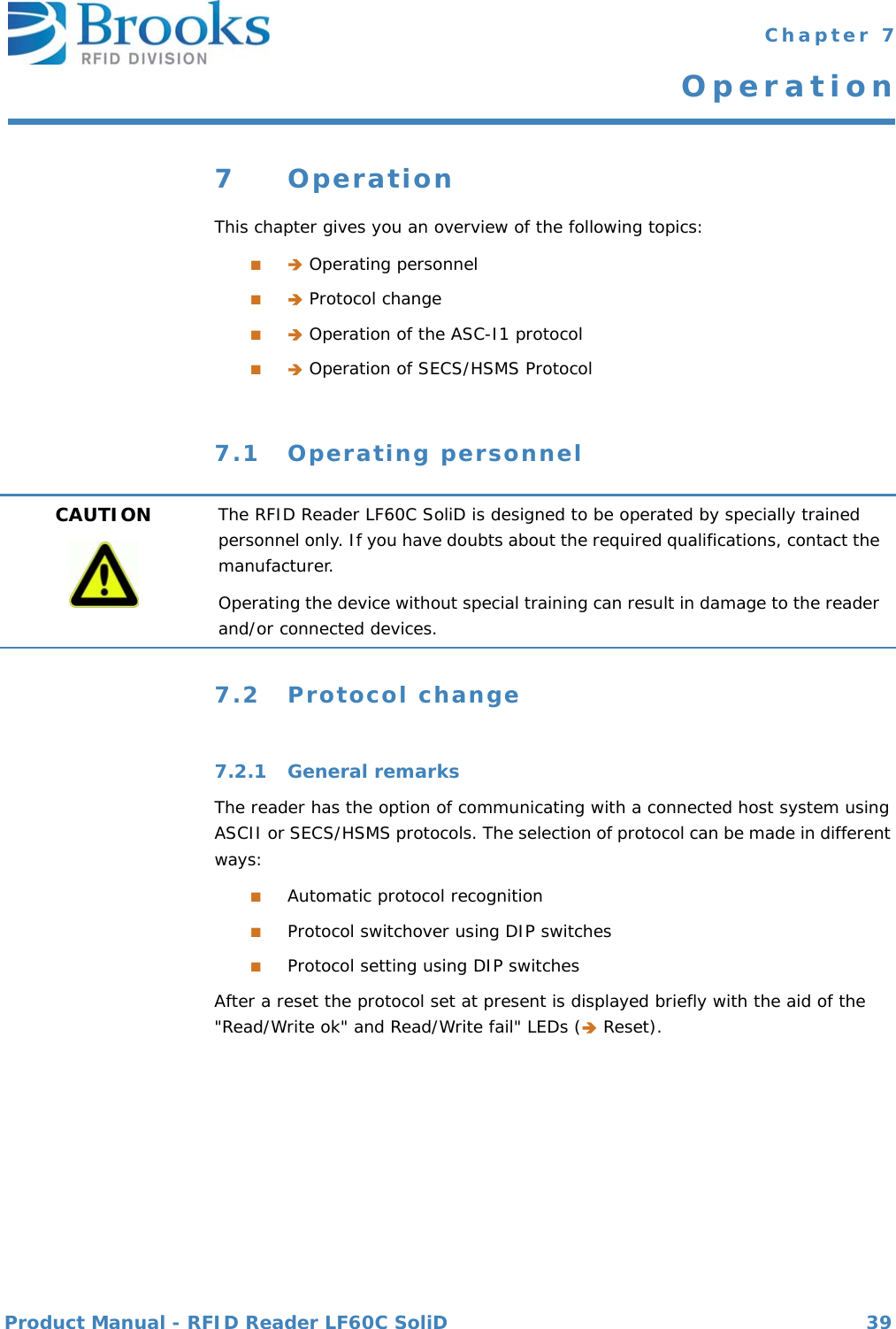
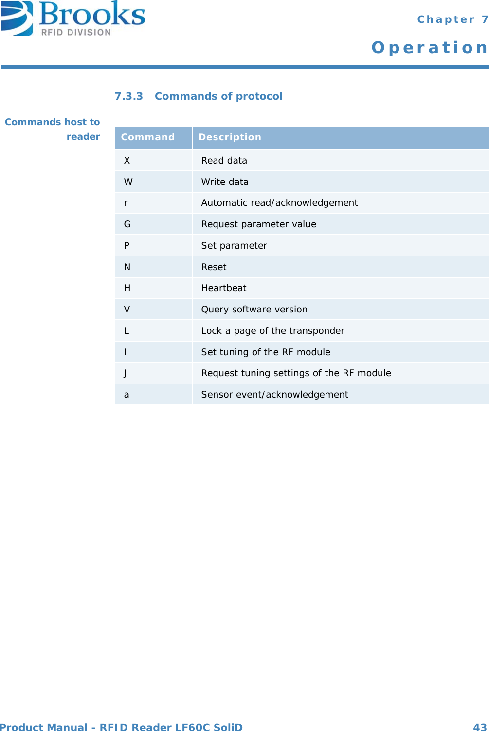
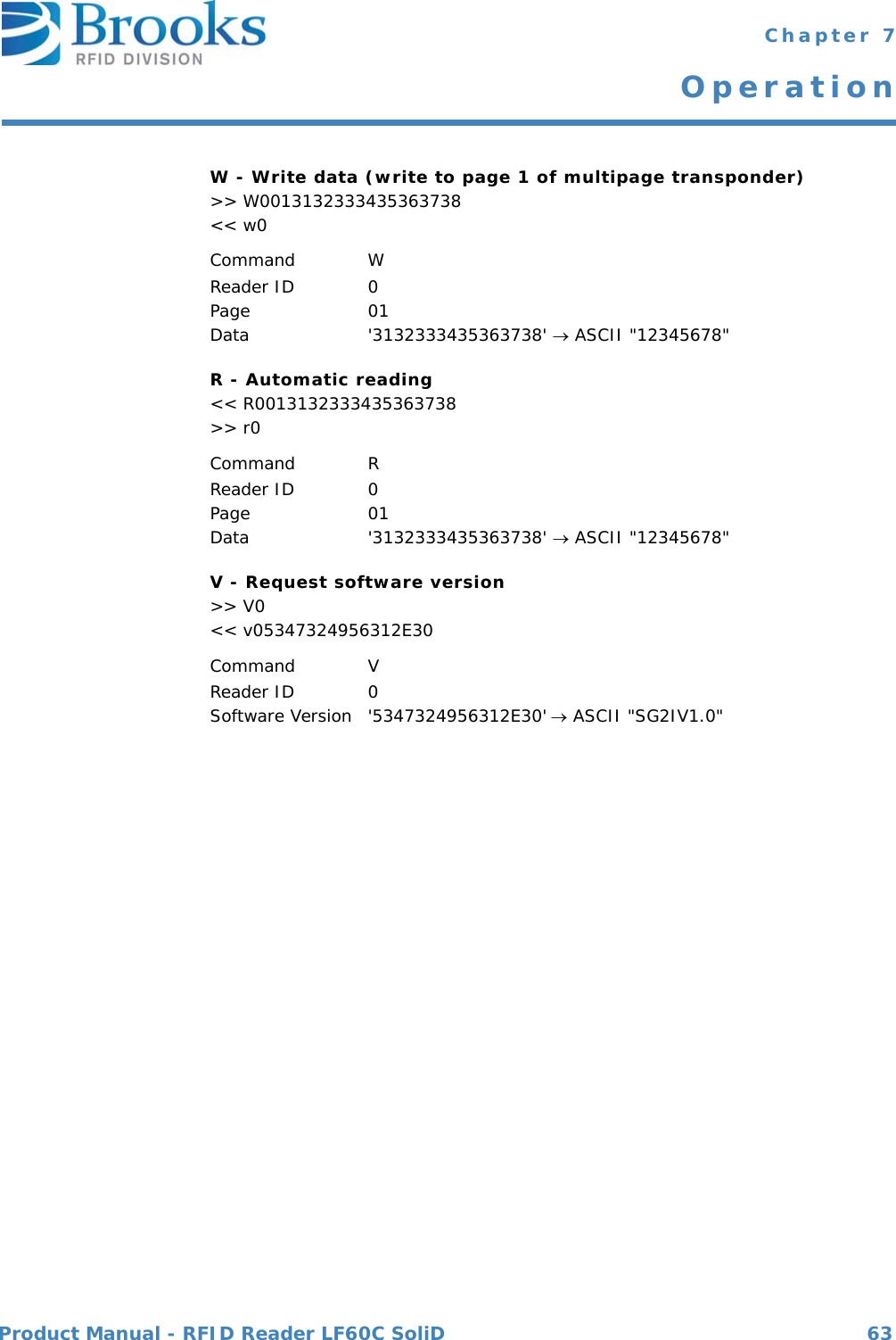
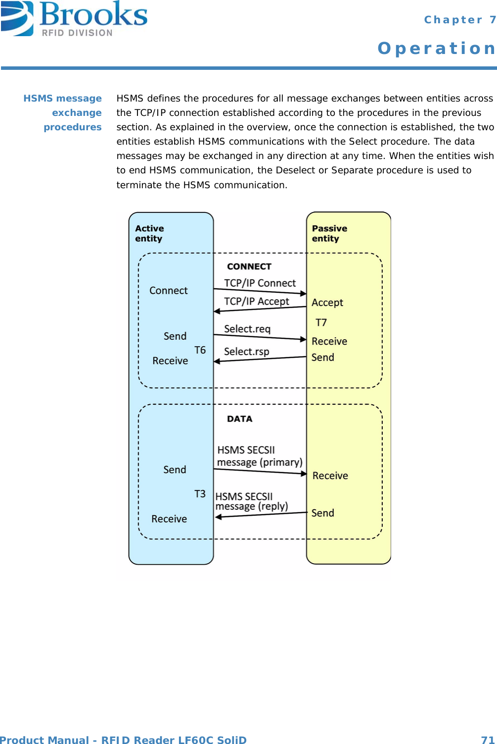
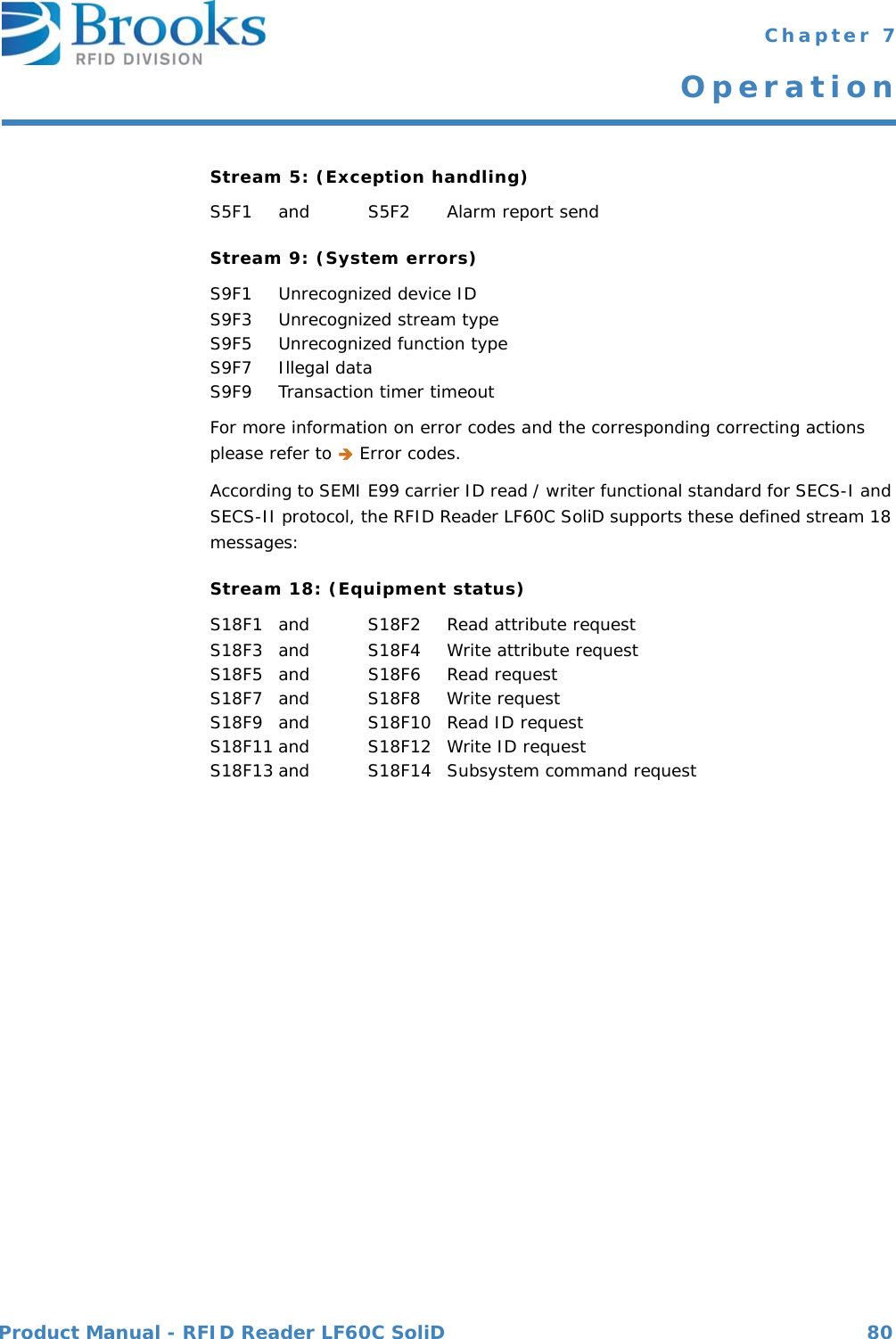
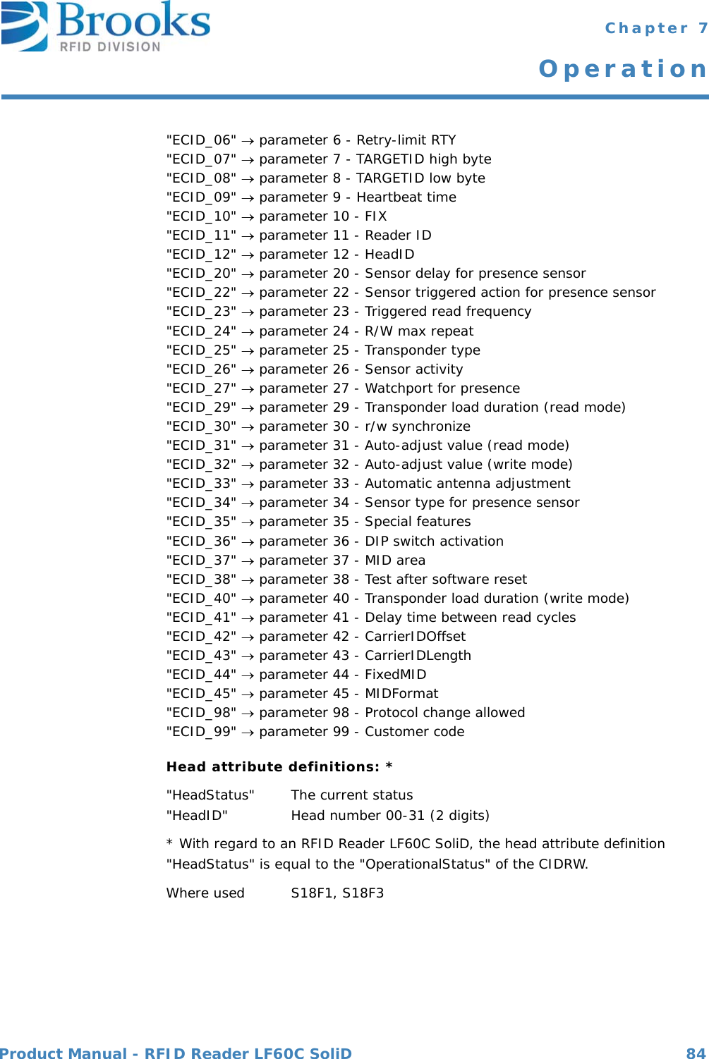
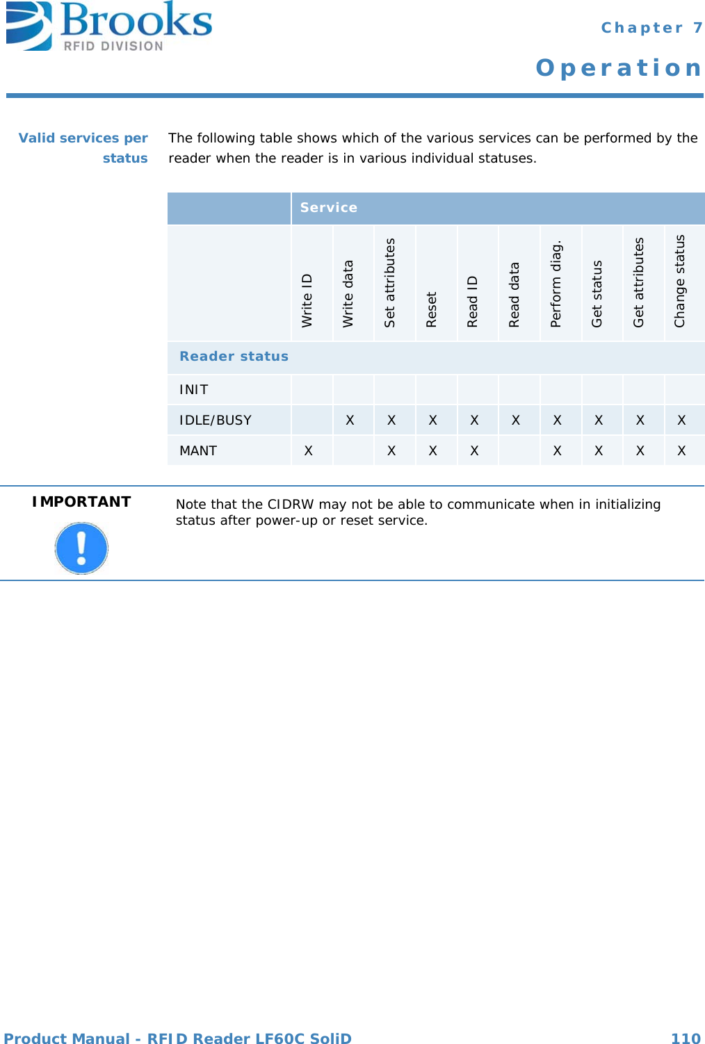
![Product Manual - RFID Reader LF60C SoliD 83 Chapter 7OperationAlarm textThe length of the alarm text is 0 to 40 characters.According to the reader version, status information about the sensor or sensors is also transmitted during a reader error message. The information should be interpreted as follows:ALTX[0] Initiator of an error message“0”: Sensor 0“1”: Sensor 1 (not available)“F”: Cannot be assignedALTX[1] Status of sensor 0“0”: Sensor not occupied“1”: Sensor is occupied“E”: Sensor status is not available“F”: Sensor not definedALTX[3] ‘:’ a colon separates the alarm text from the sensor statusesWhere used S5F1Description: Identifier for an attribute for a specific type of object.CIDRW attribute definitions:"Configuration"… Number of heads"AlarmStatus” Current CIDRW sub-status of ALARM STATUS"OperationalStatus" Current CIDRW sub-status of OPERATING"SoftwareRevisionLevel" Revision (version) of software - 8-byte maximum"CarrierIDOffset" Offset of CID in CID field (MID area)"CarrierIDLength" Length of CID in CID field (MID area)"SERIALNUM” String of Serial number"HARDWARE" String of hardware release"SELF_TEST_RESULT" Delivers the result from the last triggered self test"MANUFACTURER" String of manufacturer "ECID_00" parameter 0 - Gateway ID (ECID=0)"ECID_01" parameter 1 - Baudrate (ECID=1)"ECID_02" parameter 2 - Inter-character-timeout T1"ECID_03" parameter 3 - Block-protocol-timeout T2"ECID_04" parameter 4 - Reply-timeout T3"ECID_05" parameter 5 - Inter-block-timeout T4ALTX Format: A[max40]ALTRID Format: A[max25]](https://usermanual.wiki/Brooks-Automation/LF60C/User-Guide-2012591-Page-83.png)
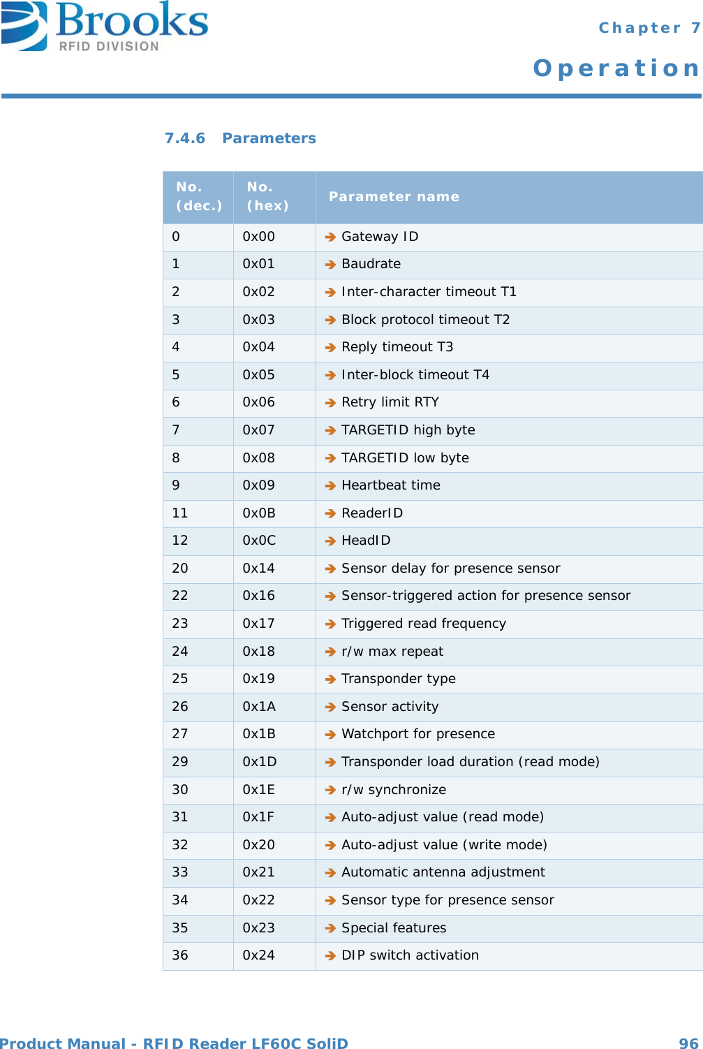
![Product Manual - RFID Reader LF60C SoliD 85 Chapter 7OperationDescription: Value of the specified attribute.CIDRW attribute definitions:"Configuration” Number of heads "01""AlarmStatus” Current CIDRW sub-status of ALARM STATUS"0" …NO"1" …ALARMS"OperationalStatus" Current CIDRW sub-status of OPERATING"IDLE” … Reader in IDLE mode"BUSY” … Reader is busy"MANT" … Maintenance mode"SoftwareRevisionLevel" Revision (version) of Software - 8-byte maximum"SERIALNUM" String of Serialnumber - 15 bytes maximum"HARDWARE" String of hardware release - 10 bytes maximum"SELF_TEST_RESULT" Delivers the result from the last triggered hardwareself test. A self test can be triggered by S18F13 withSSCMD "PerformDiagnostics""P" … No hardware errors detected"F" … Hardware errors detected"MANUFACTURER" String of manufacturer "BROOKS"ECID_00 to ECID_99 see data item ECV parameters 0 - 99Head attribute definitions:"HeadStatus" The current status"IDLE" ... Reader in IDLE mode"BUSY" ... Reader is busy"NOOP" ... Not operating"HeadID" Head number 00-31 (2 digits)"00" ... Reader 0"31" ... Reader 31Where used S18F2, S18F3ATTRVAL Format: A[max4]](https://usermanual.wiki/Brooks-Automation/LF60C/User-Guide-2012591-Page-85.png)
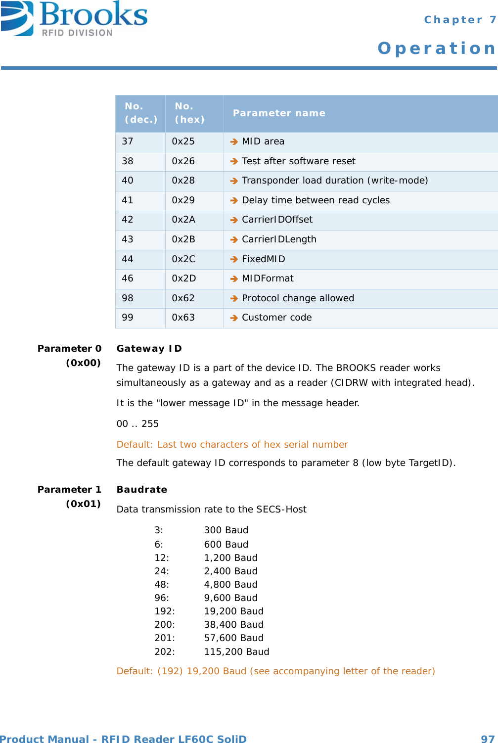
![Product Manual - RFID Reader LF60C SoliD 86 Chapter 7OperationDescription Status request valueOpStatusOperation status Maintenance or Idle "OP" ... Operating status"MT" ... Maintenance statusLEDStatus LED state "Off" ... Switch LED off"On" ... Switch LED on "Flash" ... Switch LED to flash with 1HzLedNOLED number, 1 byte "1" Status LED"2" Status LED"3" External output"4" Read OK LED"5" Read Fail LED TimeoutTimeout periodUnits SecondsRange "1" - "98""99" has a special meaning: it specifies "always". For example, a LED is turned on with the TIMEOUT value of 99; it will stay on until the host turns it off or the device is reset.Where used S18F13Description A vector or string of unformatted data.Multipage transponder DATA area depends on the MID area,can be page 1 - page 17 Read/write transponder DATA correspond to 8 byte MIDRead/only transponder DATA correspond to 8 byte MIDWhere used S18F6, S18F7CPVAL Format: A[]DATA Format: A [max 200]](https://usermanual.wiki/Brooks-Automation/LF60C/User-Guide-2012591-Page-86.png)
![Product Manual - RFID Reader LF60C SoliD 87 Chapter 7OperationMultipage-transponder (page 1 to page 17):Start the reading or writing on the following page of a multipage transponder:..."01" page 1 "81" Locked page 1... ..."11" page 17 "91" Locked page 17Read/only transponder "F0" Read only the one pageRead/only transponder "F1" Read or write only the one pageWhere used S18F5, S18F7Acknowledge code for new reader constant0 ... Parameter was set successfully1 ... Parameter could not be setWhere used S2F16DATALENGTH Format: U2Description Total bytes to be sent.The DATALENGTH corresponds to the quantity of bytes that are to be read or written. The valid range depends on the length of the MID area (parameter 37).Where used S18F5, S18F7DATASEG Format:A[2]Description Used to identify the data requested.The DATASEG corresponds to the page number (PAGEID) of the ISO 15693 transponder."00" First page of any type of transponder or first page of DATA area in case of a multipage transponder.EAC Format: B[1]](https://usermanual.wiki/Brooks-Automation/LF60C/User-Guide-2012591-Page-87.png)
![Product Manual - RFID Reader LF60C SoliD 88 Chapter 7OperationParameter number of reader (see data item ECV)Where used 2F13, S2F15Reader parameter definition. The values are displayed as decimal values.Equipment model number.Where used S1F2Material format code.20: The material port number corresponds to the sensor number and statusWhere used S3F5, S3F7 SECS message block header associated with message block in error.Where used S9F1, S9F3, S9F5, S9F7, S9F9ECID Format: U1ECV Format: U1MDLN Format: A[6]MF Format: B[1]MHEAD Format: B[10]](https://usermanual.wiki/Brooks-Automation/LF60C/User-Guide-2012591-Page-88.png)
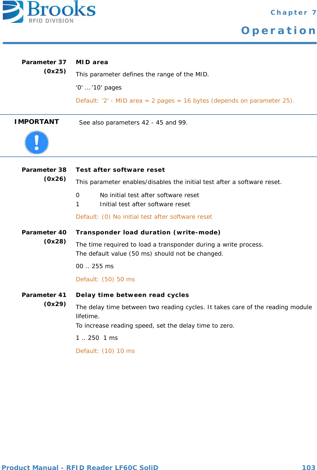
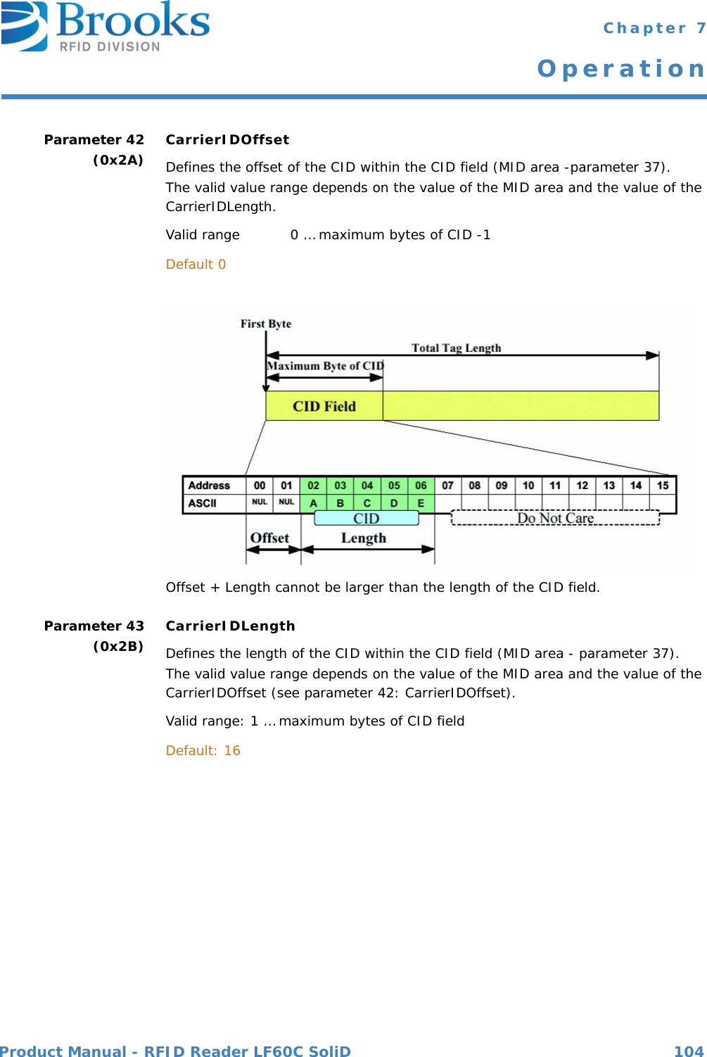
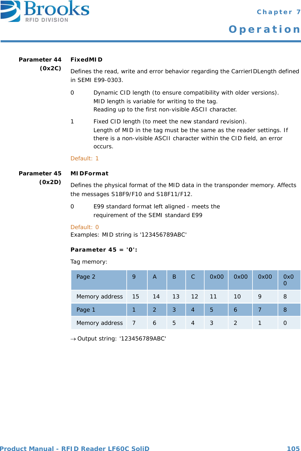
![Product Manual - RFID Reader LF60C SoliD 89 Chapter 7OperationDescription Material IDDepending on the type of transponder, it is possible to modify the length of the MID.Multipage transponder MID can be set from "0" (no MID) to "10" (MID occupies the first 10 pages (writeable))Read/write transponder MID corresponds to DATA (writeable)Read/only transponder MID corresponds to DATA (fix)Where used S18F10, S18F11 Material ID acknowledge code0 Material ID acknowledged; the presence sensor was the initiator1 Not defined 2 Material ID acknowledged - reaction on externally triggered action; the message cannot be related to any sensor>2 Material ID not acknowledgedThe data item port number PTN indicates the initiator. Where used S3F14, S3F68MID Format: AIMPORTANT Please note parameters 42 - 45.MIDAC Format: B[1]](https://usermanual.wiki/Brooks-Automation/LF60C/User-Guide-2012591-Page-89.png)
![Product Manual - RFID Reader LF60C SoliD 90 Chapter 7OperationMaterial ID acknowledge code2 Acknowledge, will send MID later in S3F13Where used S3F12Acknowledge code for OFF-LINE request.0 OFF-LINE acknowledge (reader is offline)Where used S1F16Acknowledge code for ON-LINE request.0 ON-LINE accepted (reader is online)Where used S1F18Page number of multipage, read/only and read/write transponders0x00 : First page of the data area of a multipage transponder.Multipage transponder (pages 1 to 17):If only one page of the multipage transponder is read, note the following:0x01 : (1) page 1 0x81 : (129) locked page 1... ...0x11 : (17) page 17 0x91 : (146) locked page 17Read-only transponder:0xF0 : (240) Read one page onlyRead/write transponder:0xF1 : (241) Read or write one page onlyWhere used S3F11MIDRA Format: B[1]OFLACK Format: B[1]ONLACK Format: B[1]PAGE_ID Format: B[1]](https://usermanual.wiki/Brooks-Automation/LF60C/User-Guide-2012591-Page-90.png)
![Product Manual - RFID Reader LF60C SoliD 91 Chapter 7OperationThe cassette identifier that has been read or will be written. The PAGEDATA corresponds to the value of a transponder page.PAGEDATA [0] Corresponds to the page number. The value of the page number is displayed in the data item "PAGE_ID". PAGEDATA [1] The 8 bytes (one page) of the transponder ID follow.PAGEDATA [8]Where used S3F7, S3F12, S3F13, S3F65 Information about the status of up to two sensors and the initiator of the message.The second sensor is not implemented yet.For special applications, the reading process of the transponder reader is triggered by two sensors. In this case it is necessary to distinguish between the two sensors. The initiator represents the number of the sensor that has caused the message.Default: Only sensor 0 is defined.bit 7 ........ bit 0Initiator Sensor 1 Sensor 0Sensor 0: bit 0 - bit 2The current status of sensor 0 is described in three bits.0 Sensor not occupied1 Sensor occupied7 Sensor not definedSensor 1: bit 3 - bit 5 (defined for future developments)The current status of sensor 1 is described in three bits.0 Sensor not occupied1 Sensor occupied7 Sensor not definedInitiator: bit 6 - bit 7The initiator represents the number of the sensor that has caused the message. 0Sensor 01 Sensor 1 (not implemented yet)3 Cannot be assignedWhere used S3F5, S3F7, S3F12, S3F13, S3F67PAGEDATA Format: B[9]PIN Format: B[1]](https://usermanual.wiki/Brooks-Automation/LF60C/User-Guide-2012591-Page-91.png)
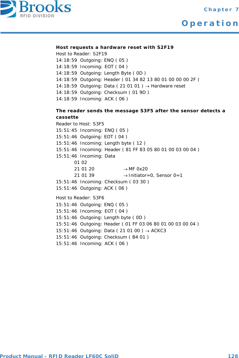
![Product Manual - RFID Reader LF60C SoliD 92 Chapter 7OperationDescription Preventive maintenance information"NE "… Normal execution"MR "… Maintenance requiredWhere used S18F2, S18F4, S18F8, S18F10, S18F12, S18F14Reset acknowledge code0 … Reset to be done1 … Reset could not be doneWhere used S2F20Reset code1… Power-up reset2 … Software reset Where used S2F19Stored SECS message block header. Only the last message is stored, which must still be confirmed by the host. Where used S9F9Software revision code.Where used S1F2PM Information Format: A[2]RAC Format: B[1]RIC Format: B[1]SHEAD Format: B[10]SOFTREV Format: A[max 6]](https://usermanual.wiki/Brooks-Automation/LF60C/User-Guide-2012591-Page-92.png)
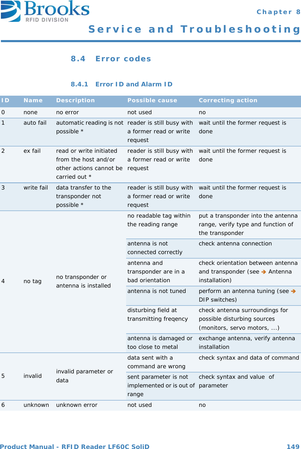
![Product Manual - RFID Reader LF60C SoliD 93 Chapter 7OperationDescription: Result information on the status of the request concerning the service request."NO" Normal operationIndicates the success of the requested action."EE" Execute errorCannot read tag data. Cannot read ID sequence.However, equipment is normal."CE" Communication errorSyntax error of message or message format or value."HE" Hardware errorID reader/writer head fault, ID reader/writer head is powered off."TE" Tag errorFor more information on error codes and the corresponding correcting actions please refer to Error codes.Where used S18F2, S18F4, S18F6, S18F8, S18F10, S18F12, S18F14SSACK Format: A[2]](https://usermanual.wiki/Brooks-Automation/LF60C/User-Guide-2012591-Page-93.png)
![Product Manual - RFID Reader LF60C SoliD 94 Chapter 7OperationDescription: Indicates an action to be performed by the subsystem.Used to differentiate between the different subsystem commands indicated."ChangeStatus" … Change statusCPVAL: <OpStatus>"GetStatus" … Get status"Reset" … Reset CIDRW"PerformDiagnostics"… A hardware self test is performed. To get the result read parameter "SELF_TEST_RESULT""ADJUST" … Triggers a automatic antenna adjustment"DefaultParams" … Set default reader parameters "SetLED" … Set one of the device LEDsCPVAL's: 1.<LEDStatus>2.<Timeout>3.<LEDNo>Where used S18F13 Description Provides status information of a subsystem component.Consists of PM Information and the current values of theCIDRW attributes AlarmStatus, OperatingStatus, and HeadStatus.List of a Status L,4 <PMInformation> <AlarmStatus> <OperatingStatus> <HeadStatus>For data items OperatingStatus and HeadStatus, see data item ATTRVAL.Where used S18F2, S18F4, S18F8, S18F10, S18F12, S18F14SSCMD Format: A[max 18]STATUS Format: A[max 5]](https://usermanual.wiki/Brooks-Automation/LF60C/User-Guide-2012591-Page-94.png)
![Product Manual - RFID Reader LF60C SoliD 95 Chapter 7OperationDescription Identifies where a request for action or data is to be applied. Alternatively, you can use the HeadID.See also reader parameter definitions (data item ECV) parameter 7, 8 and 12.The 4 ASCII character TARGETID is changeable, and definedin parameter 7 and 8 ("ECID_07", "ECID_08").The 2 ASCII character HeadID is changeable, and defined in parameter 12 ('ECID_12').Where used S18F1, S18F3, S18F5, S18F7, S18F9, S18F11, S18F13TARGETID Format: A[max 4]](https://usermanual.wiki/Brooks-Automation/LF60C/User-Guide-2012591-Page-95.png)
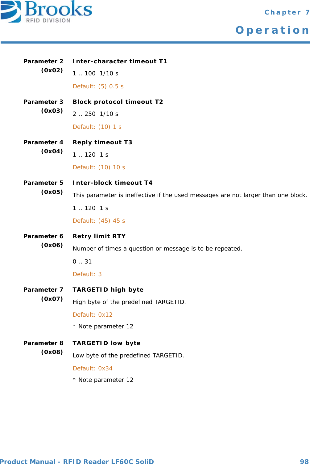
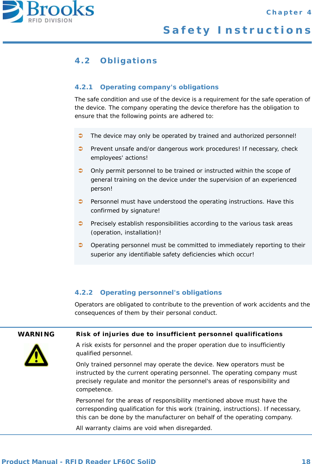
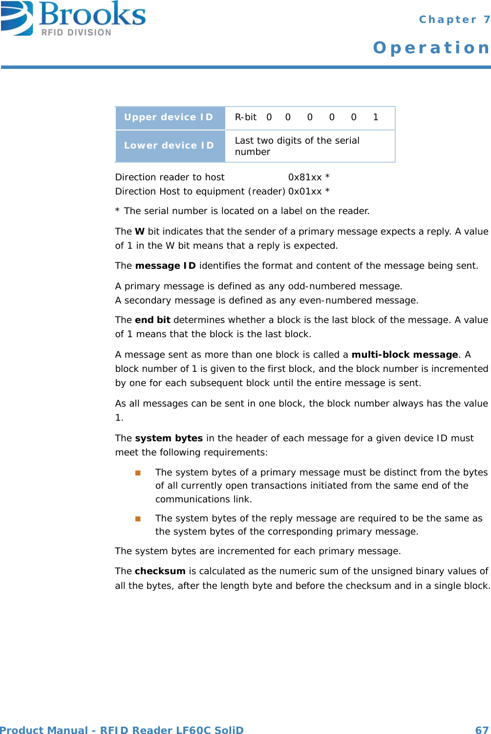
![Product Manual - RFID Reader LF60C SoliD 111 Chapter 7Operation7.4.8 Message detailsEquipment status S1F0: ABORT TRANSACTION (reader <-> host)Used instead of an expected reply to abort a transaction. Function 0 is defined in every stream and has the same meaning in every stream.S1F0 W . * Header onlyS1F1: ARE YOU THERE REQUEST (reader <-> host, reply)Establishes if the gateway/reader or host is online.S1F1 W . * Header onlyS1F2: ON-LINE DATA (host -> reader)The host signals that it is online.S1F2 <L[2] <A[6]MDLN > <A[6]SOFTREV > > S1F2: ON-LINE (reader -> host)The reader signals that it is online.S1F2 <L[2] <A[6]MDLN > <A[6]SOFTREV > >.S1F15: REQUEST OFF_LINE (host ->reader, reply)The reader is requested to change the communication status to offline.The reader can only be set online again by using message S1F17 (or reset S2F19); all other messages are aborted by the SxF0 message.S1F15 W. *Header onlyS1F16: OFFLINE ACKNOWLEDGE (reader -> host)Acknowledge.S1F16<B[1]OFLACK>.](https://usermanual.wiki/Brooks-Automation/LF60C/User-Guide-2012591-Page-111.png)
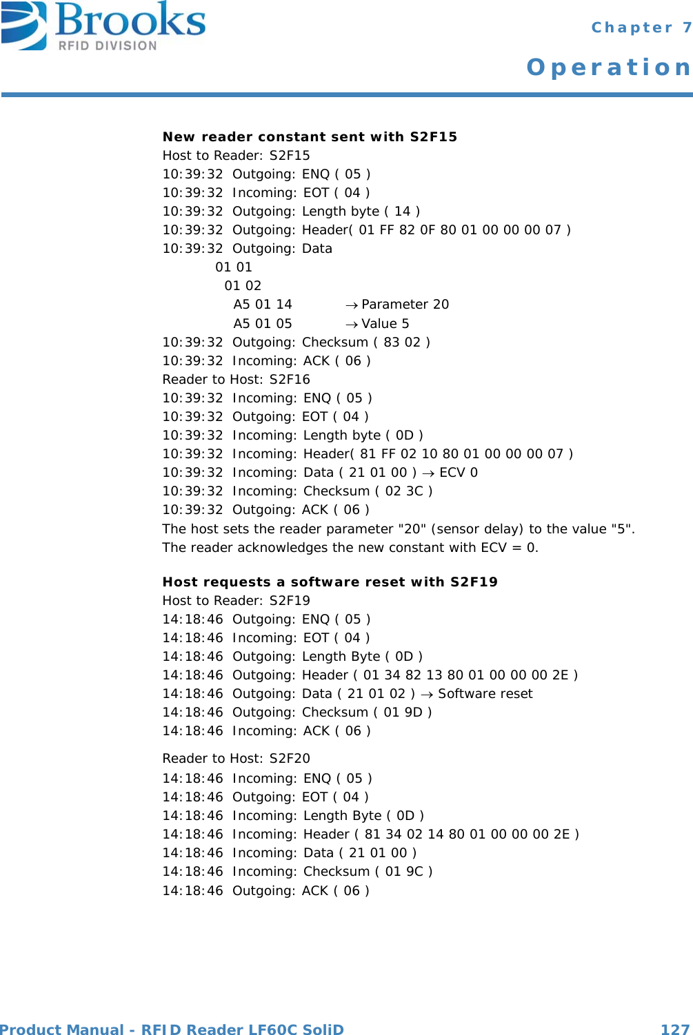
![Product Manual - RFID Reader LF60C SoliD 112 Chapter 7OperationS1F17: REQUEST ON_LINE (host -> reader, reply)The reader is requested to change the communication status to online.S1F17 W.*Header onlyS1F18: ONLINE ACKNOWLEDGE (reader -> host)Acknowledge.S1F18<B[1]ONLACK>.Equipment control S2F0: ABORT TRANSACTION (reader <-> host)Used instead of an expected reply to abort a transaction. Function 0 is defined in every stream and has the same meaning in every stream.S2F0 W . * Header onlyS2F13: EQUIPMENT CONSTANT REQUEST (host-> reader, reply)The host requests a constant from the reader.S2F13 W <L[1] <U1[1] ECID>>.S2F14: EQUIPMENT CONSTANT DATA (reader -> host)The reader sends the requested constant to the host.S2F14 <L[1] <U1[1] ECV> >.S2F15: NEW EQUIPMENT CONSTANT SENT (host-> reader, reply)The host changes a reader constant.S2F15 W <L[1] <L[2] <U1[1] ECID> <U1[1] ECV> > >.](https://usermanual.wiki/Brooks-Automation/LF60C/User-Guide-2012591-Page-112.png)
![Product Manual - RFID Reader LF60C SoliD 113 Chapter 7OperationS2F16: NEW EQUIPMENT CONSTANT ACKNOWLEDGE (reader -> host) The reader acknowledges the setting of the reader constant.S2F16 <B[1] EAC>.S2F19: RESET SEND (host -> reader, reply)The host requests the reader to reset the hardware and software.If a heartbeat time is set (parameter 9), the reader sends an S1F1 message when the reset is finished. The power-up reset requires a few seconds.S2F19 W <B[1] RIC>.S2F20: RESET ACKNOWLEDGE (reader -> host)The reader acknowledges the reset.This message will only appears if a software reset (RIC=2) is triggered.S2F20 <B[1] RAC>.Material status S3F0: ABORT TRANSACTION (reader <-> host)Used instead of an expected reply to abort a transaction. Function 0 is defined in every stream and has the same meaning in every stream.S3F0 W. * Header OnlyS3F5: CASSETTE FOUND SEND (reader -> host, reply)The reader sends the information that a cassette was detected by the presence sensor. This message is sent only if a sensor is connected and activated (see parameters 27 'watchport' and 26 'sensor activity').S3F5 W. <L[2] <B[1] MF> <B[1] PTN>>.S3F6: CASSETTE FOUND ACKNOWLEDGE (host -> reader)The host acknowledges the cassette found message.S3F6 <B[1] ACKC3>.](https://usermanual.wiki/Brooks-Automation/LF60C/User-Guide-2012591-Page-113.png)
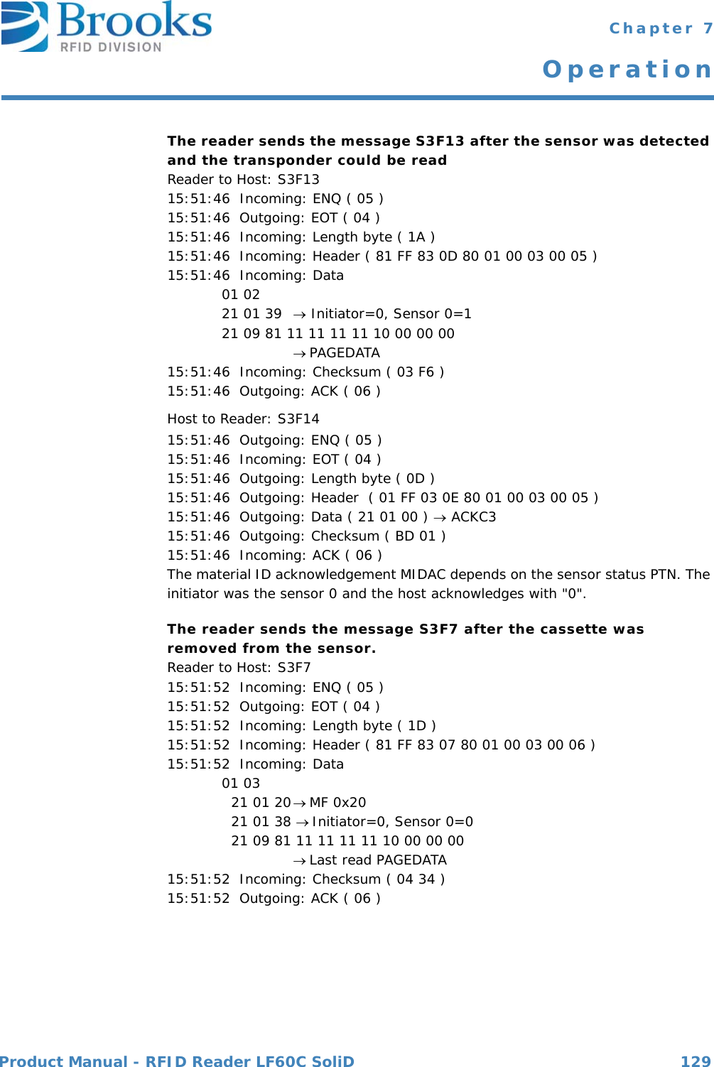
![Product Manual - RFID Reader LF60C SoliD 114 Chapter 7OperationS3F7: CASSETTE LOST SEND (reader -> host, reply)The reader sends the information that the cassette was removed from the I/O port (presence sensor).This message is sent only if a sensor is connected and activated (see parameters 27 'watchport' and 26 'sensor activity'). The PAGEDATA can be given only if the PAGEDATA that was read last is still available.S3F7 W. <L[3] <B[1] MF > <B[1] PTN > <B[9] PAGEDATA >* >.* a zero-length PAGEDATA indicates that no PAGEDATA is available (case of error)S3F8: CASSETTE LOST ACKNOWLEDGE (host -> reader)The host acknowledges the cassette lost message.S3F8 <B[1] ACKC3>.S3F11: READ MID AT I/O PORT (host -> reader, reply)The host requests the reader to read the PAGEDATA of the given PAGE_ID.S3F11 W <B[1] PAGE_ID>.S3F12: READ ACKNOWLEDGE (reader -> host)The reader only acknowledges the receipt of the reading command.The PAGEDATA is sent later.S3F12 <L[3] <B[1] PTN>* <B[1] MIDRA> <B[9] PAGEDATA>**>.* a zero-length PTN indicates that no PTN is available** a zero-length PAGEDATA indicates that no DATA is available](https://usermanual.wiki/Brooks-Automation/LF60C/User-Guide-2012591-Page-114.png)
![Product Manual - RFID Reader LF60C SoliD 115 Chapter 7OperationS3F13: RETURN READ MID (reader -> host, reply)The reader sends the ID of the cassette at the I/O port to the host.S3F13 W <L[2] <B[1] PTN> <B[9] PAGEDATA >>.S3F14: MID ACKNOWLEDGE (host -> reader)The host acknowledges the received data.S3F14 <B[1] MIDAC>.S3F65: WRITE MID AT I/O PORT (host -> reader, reply)The host requests that the reader write the PAGEDATA.S3F65 W <B[9] PAGEDATA >S3F66: WRITE ACKNOWLEDGE (reader -> host)The reader only acknowledges the receipt of the write command.The write acknowledge is sent later.S3F66 <L[2] <B[1] MIDRA> <B[9] PAGEDATA > >.S3F67: RETURN WRITE SUCCESS (reader -> host, reply)The reader reports the successful writing of the transponder. The reader sends information about the presence sensor.S3F67 W <B[1] PTN>.S3F68: WRITE SUCCESS ACKNOWLEDGE (host -> reader)The host acknowledges the received data.S3F68 <B[1] MIDAC>.](https://usermanual.wiki/Brooks-Automation/LF60C/User-Guide-2012591-Page-115.png)
![Product Manual - RFID Reader LF60C SoliD 116 Chapter 7OperationS3F73: LOCK MID AT I/O PORT (host -> reader, reply)The host requests the reader to lock the requested page.S3F73 W<B[1] PAGE_ID>.S3F74: LOCK ACKNOWLEDGE (reader -> host)The reader acknowledges the receipt of the locking command only.The locking acknowledgement is sent later.S3F74 <L[2] <B[1] MIDRA> <B[9] PAGEDATA > >.S3F75: RETURN LOCK SUCCESS (reader -> host, reply)The reader reports the successful locking of the given page. The reader sends information about the presence sensor.S3F75 W <B[1] PTN>.S3F76: LOCK SUCCESS ACKNOWLEDGE (host -> reader)The host acknowledges the receipt of the lock success message (S3F75).S3F76 <B[1] MIDAC>.Exception handling S5F0: ABORT TRANSACTION (reader <-> host)Used instead of an expected reply to abort a transaction. Function 0 is defined in every stream and has the same meaning in every stream.S5F0 W . * Header onlyATTENTION Locking a transponder page is permanent.You cannot unlock a transponder page.](https://usermanual.wiki/Brooks-Automation/LF60C/User-Guide-2012591-Page-116.png)
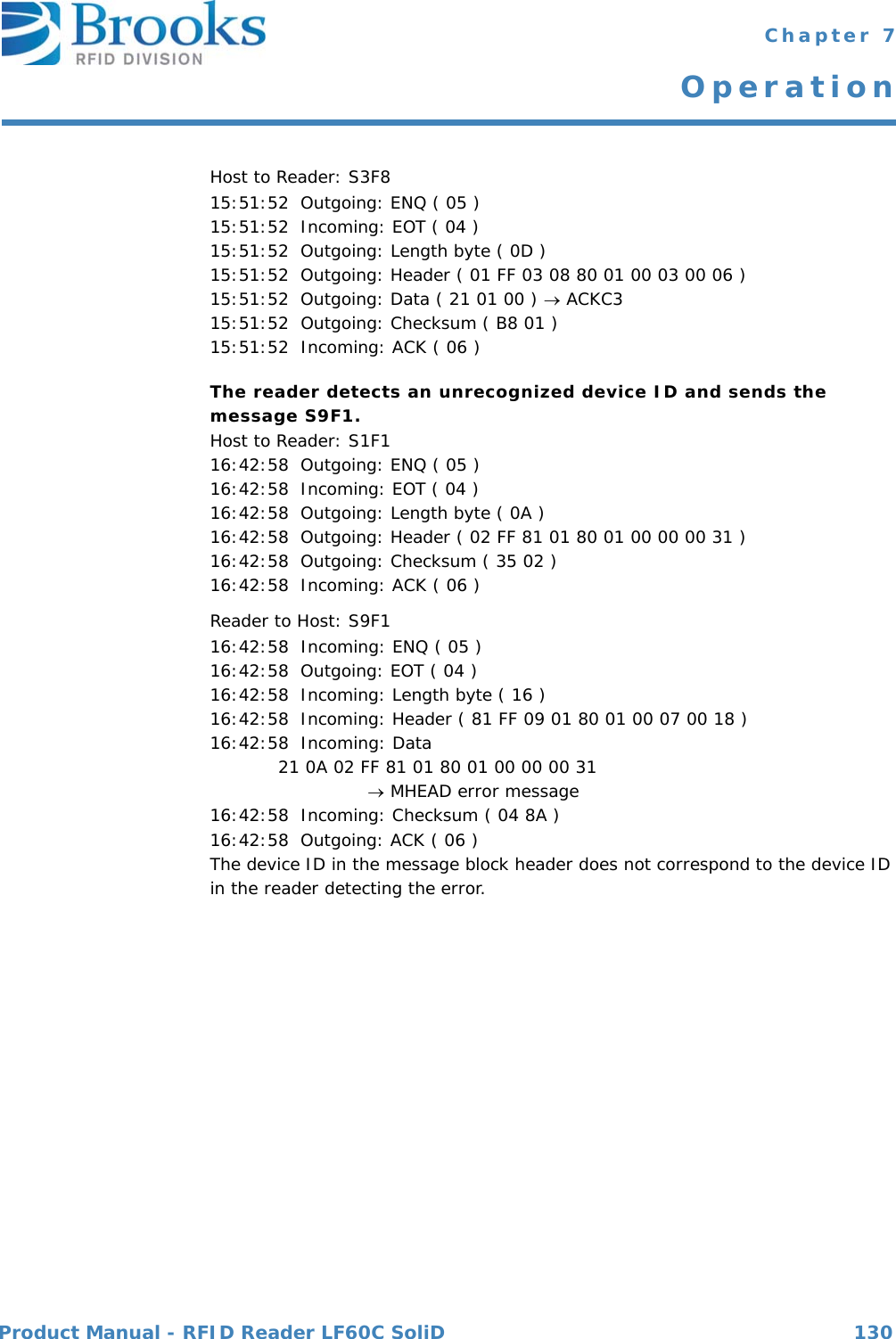
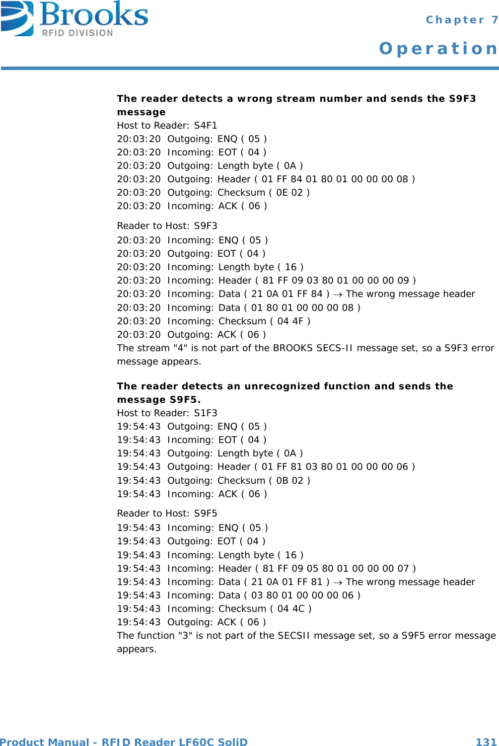
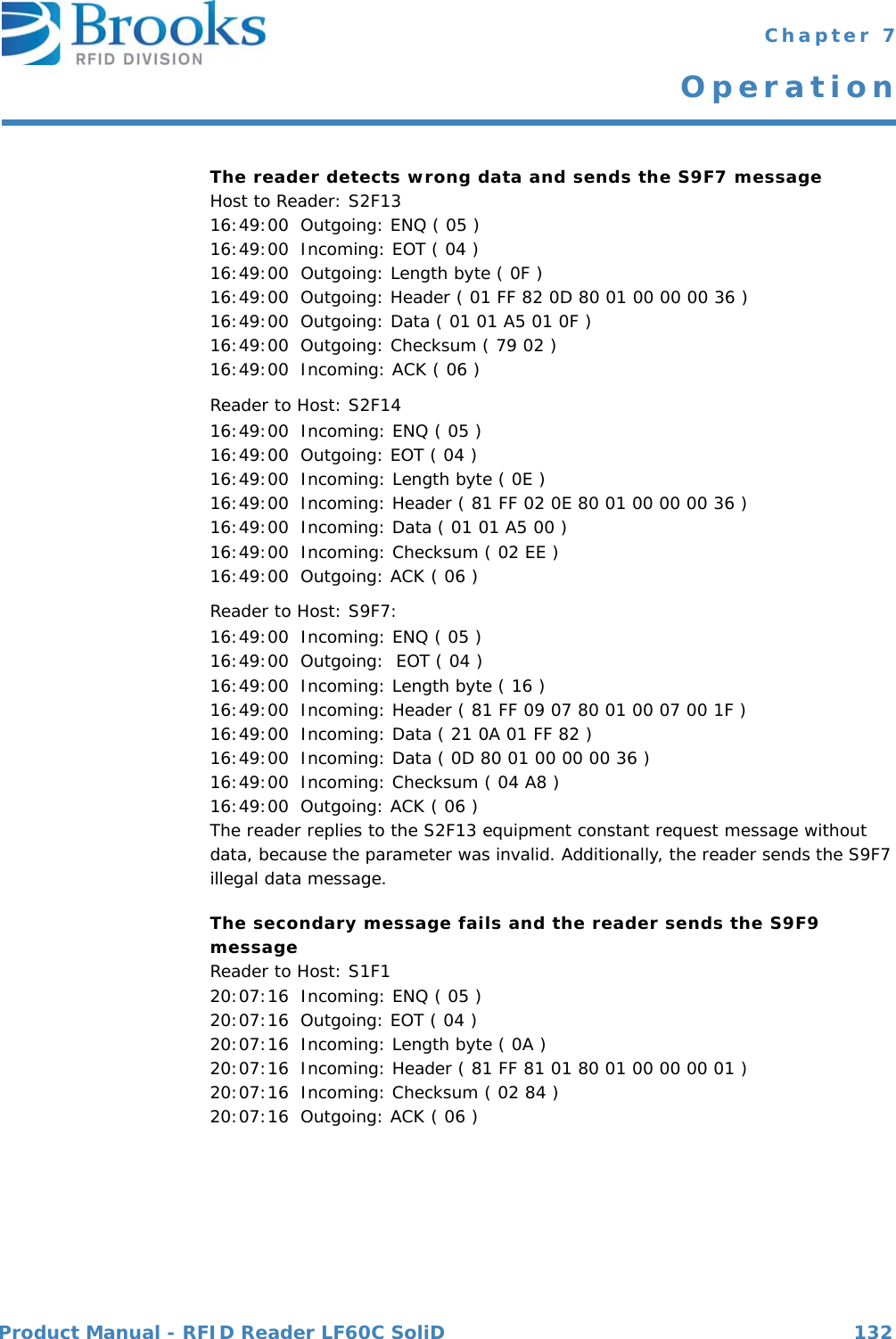
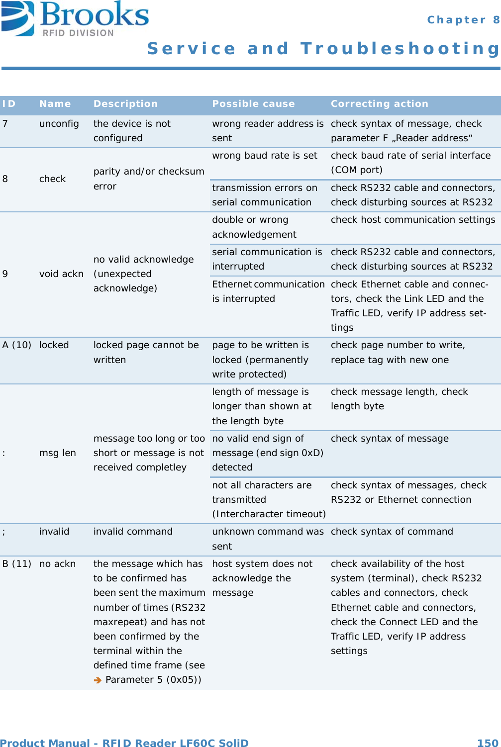
![Product Manual - RFID Reader LF60C SoliD 117 Chapter 7OperationS5F1: GATEWAY READER ALARM REPORT SEND (reader -> host, reply)The reader reports all errors to the host.S5F1 W <L[3] <B[1] ALCD >* alarm code byte <B[1] ALID > * alarm ID <A[MAX 40] ALTX >* alarm text >. S5F2: ALARM REPORT ACKNOWLEDGE (host -> reader)The host acknowledges an alarm.S5F2 <B[1] ACKC5>.Exception handlingSystem errors S9F1: UNRECOGNIZED DEVICE ID (reader -> host)The device ID in the message block header does not correspond to the equipment device ID.S9F1<B[10] MHEAD > .S9F3: UNRECOGNIZED STREAM TYPE (reader -> host)The reader does not recognize the stream type in the message block header.S9F3< B[10] MHEAD > .S9F5: UNRECOGNIZED FUNCTION TYPE (reader -> host)The reader does not recognize the function number in the message block header.S9F5< B[10] MHEAD > .S9F7: ILLEGAL DATA (reader -> host)The reader does not recognize the data in the message.S9F7 < B[10] MHEAD > .](https://usermanual.wiki/Brooks-Automation/LF60C/User-Guide-2012591-Page-117.png)
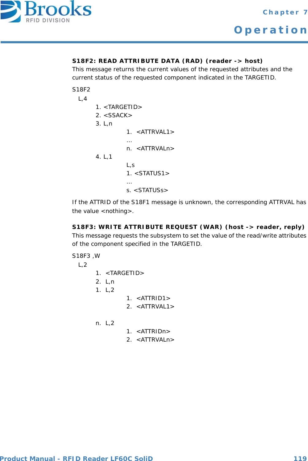
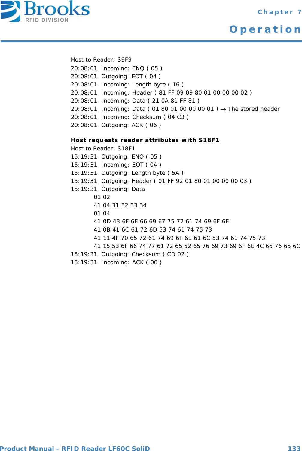
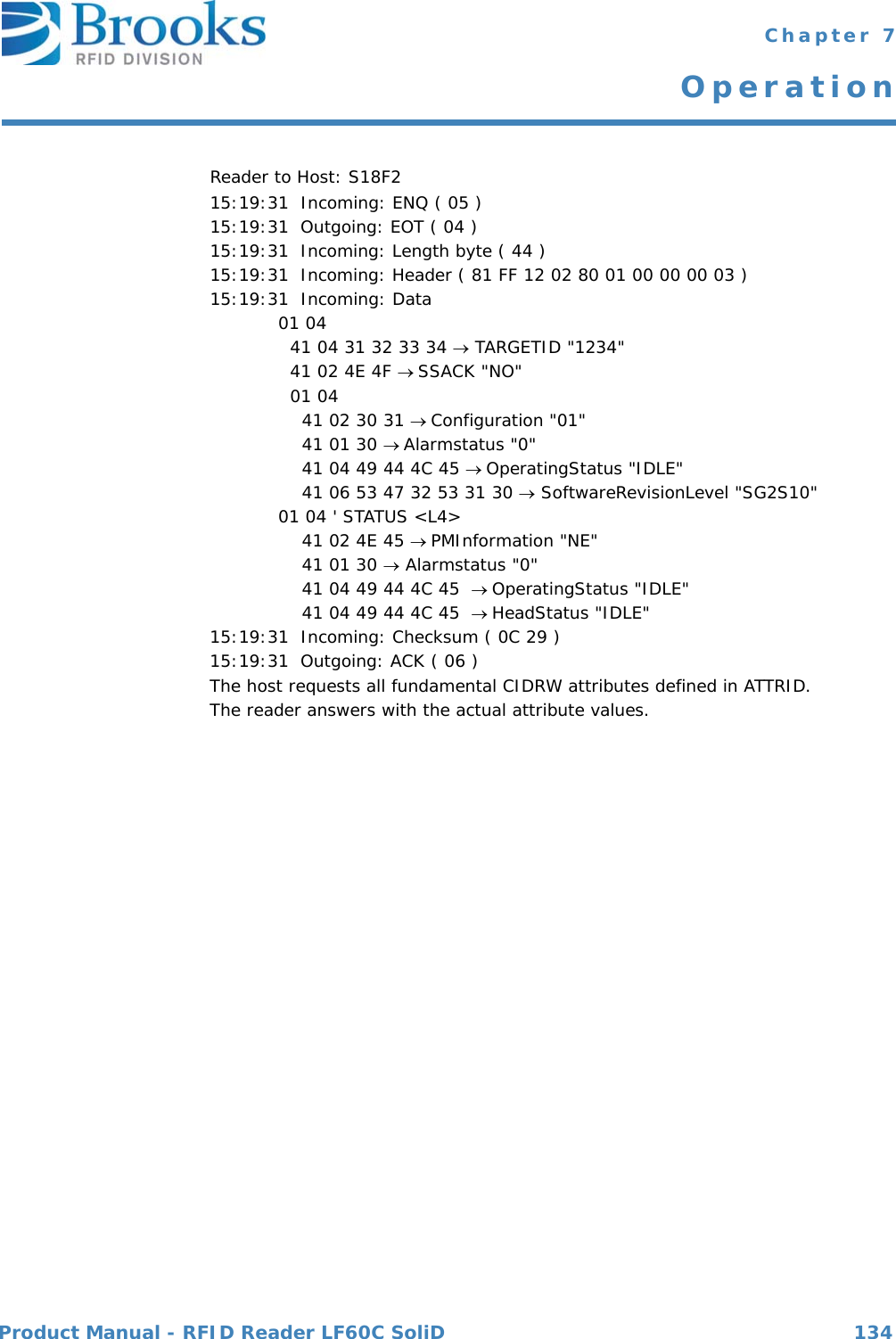
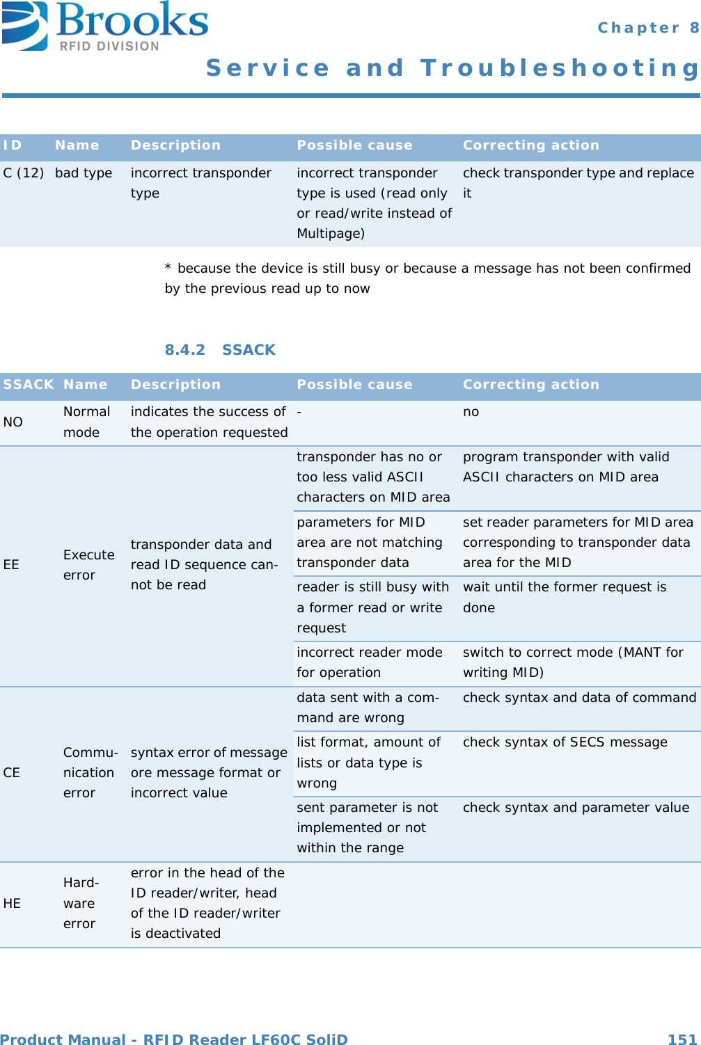
![Product Manual - RFID Reader LF60C SoliD 118 Chapter 7OperationS9F9: TRANSACTION TIMER TIMEOUT (reader -> host)This message indicates that a transaction timer has timed out and that the corresponding transaction was aborted. Only the last sent message (which must be confirmed by the host) is stored and controlled.S9F9 < B[10] SHEAD > .For more information on error codes and the corresponding correcting actions please refer toSubsystem controland data S18F0: ABORT TRANSACTION (reader <-> host)Used instead of an expected reply to abort a transaction. Function 0 is defined in every stream and has the same meaning in every stream.S18F0 W . * Header onlyS18F1: READ ATTRIBUTE REQUEST (RAR) (host -> reader, reply)This message requests the current values of specific attributes of the subsystem component indicated in the TARGETID.S18F1 WL,2 1. <TARGETID>2. L,n 1. <ATTRID1> …n. <ATTRIDn>](https://usermanual.wiki/Brooks-Automation/LF60C/User-Guide-2012591-Page-118.png)