Brooks Automation SAR Inductive Tag System User Manual 1 1
Brooks Automation (Germany) GmbH RFID Division Inductive Tag System 1 1
Users Manual

Page 1 of 15
2003-03-21
Release 1.1
ID: ID030017
Software Reticle Read-Write Station Stand Alone
Technical Reports

Software Reticle Read – Write Station – Stand Alone
Technical Reports, Release 1.1
Page 2 of 15
1 HARDWARE DESCRIPTION.................................................................. 3
2 SOFTWARE SPECIFICATION............................................................. 4
3 HARDWARE........................................................................................... 6
3.1 BAR CODE READER ............................................................................. 6
3.2 RETICLE READ / WRITE STATION ......................................................... 6
4 SOFTWARE............................................................................................ 7
4.1 FUNCTIONALITY OF BUTTONS.............................................................. 7
4.2 MENU MODE....................................................................................... 8
4.3 DOWNLOAD ........................................................................................ 9
5 FLOWCHARTS.................................................................................... 10
5.1 NORMAL MODE..................................................................................10
5.2 17 PAGE MODE ..................................................................................11
5.3 MENU MODE.....................................................................................12
5.4 BRIGHTNESS MODE ............................................................................13
6 ASCII TABLE ....................................................................................... 14
IMPORTANT NOTE.................................................................................. 3

Software Reticle Read – Write Station – Stand Alone
Technical Reports, Release 1.1
Page 3 of 15
1 Hardware Description
At the back side of the Reticle Read/Write Station is one RS232 Sub-D male
connector labeled with Barcode Reader. The barcode reader P302FZY has to be
connected there. The power supply for this unit has to be connected to the female
connector at the back.
Connect the external power supply (24V) to the connector which is labeled with
power supply, and the reader starts working. The RF Tag reader needs about 3
seconds for initialization. The antenna is justified and the display will be initiated.
After this the reader shows the current software version and it is in operation
mode.
Important Note
This device complies with Part 15 of the FCC rules. Operation is subject to the
following two conditions: (1) This device may not cause harmful interference, and
(2) this device must accept any interference received, including interference that
may cause undesired operation.
CAUTION:
Any changes or modifications not expressly approved by the party responsible for
compliance could void the user's authority to operate the equipment.
Software Reticle Read – Write Station – Stand Alone
Technical Reports, Release 1.1
Page 4 of 15
2 Software Specification
The Reticle Read/Write Station is used to write the RSP data, which will be read
from the barcode labels on the top of the RSP, to the RF tag of the RSP.
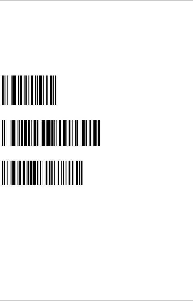
Barcode Data:
All bar codes are code 69 labels.
Label one is the product name, the second is the layer / version and the third is
the CID.
The information on the labels have to be written to the tag as follows:
Page1: lower CID right justified
Page2: upper CID right justified
Page3: first characters of product names left justified
Page4: remaining characters of product names left justified
Page5: layer / version left justified
Example:
BC data:
Product Name: 1X30SA
Layer / Version: MT52MB2
CID: 900630
RF tag data:
Byte 1 2 3 4 5 6 7 8
Page1 0 0 9 0 0 6 3 0
Page2 0 0 0 0 0 0 0 0
Page3 1 X 3 0 S A 0x00 0x00
Page4 0x00 0x00 0x00 0x00 0x00 0x00 0x00 0x00
Page5 M T 5 2 M B 2 0x00
Pages 6 .. 17 are filled with the blank byte filler character (see section 4.2).
The product name can be 1-16 characters long. The layer/version can be 1-8
characters long. Any unused bytes on the RF tag are filled with user configurable
filler characters (see section 4.2).

Software Reticle Read – Write Station – Stand Alone
Technical Reports, Release 1.1
Page 5 of 15
Logistical layout of functionality:
1. RSP will be placed on Reticle Read / Write Station.
2. The RF tag will be read automatically and the result will be shown on the
display.
3. The operator writes the label data to the tag. Therefore he reads the
labels with the bar code reader. If the bar codes were read correctly the
operator verifies the data. If everything was OK the operator presses the
‘Write’ button to transmit the data to the RF tag. Not used bytes will be
filled with values which are stored as parameters in the software.
4. After a successful writing the pod could be removed from the unit.
5. It is possible to verify the tag data against the bar code labels. Therefore
the operator presses the ‘Verify’ button and reads the labels ones more.
After that the tag reader gets the information from the RF tag. The
software checks the data of both the tag and the bar code and reports
any error.
6. If the operator reads a wrong label it is possible to clear the data /
memory by pressing the ‘Reset’ button.
Software Reticle Read – Write Station – Stand Alone
Technical Reports, Release 1.1
Page 6 of 15
3 Hardware
3.1 Bar Code Reader
The barcode works with an ASCII protocol which uses the following settings,
COM settings: 38.400,N,8,1 (baud rate, parity, data bits, stop bits).
The bar code reader is configured as follows:
1.Set all defaults:
2. Fujitsu RS-232C
3. Baud rate 38.400
Note: If the BCR is not configured you have to read these labels in the right order.
3.2 Reticle Read / Write Station
The tag reader includes an RF module which is working on the frequency of
134.2 kHz. To display the data, the device has a dot character display module
with four lines and 40 signs per line. Additional the unit includes a membrane
keyboard with four buttons. The equipment is designed to handle any SEMI-E111
compliant carrier.

Software Reticle Read – Write Station – Stand Alone
Technical Reports, Release 1.1
Page 7 of 15
4 Software
After the equipment was connected to the power supply, the tag reader tune the
antenna automatically. If no RSP is placed on the station, the software version is
displayed on the display.
4.1 Functionality of Buttons
The ‘Read’ button starts reading all 17 pages of the tag and displays the main
contents (product name, version/layer, CID) on the display. During the reading
the first line of the display shows “RF Tag is reading …”.
The ‘Write’ button initiate the data transfer of the read bar codes to the tag. At first
the barcode labels have to be read with the BCR gun. The first line of the display
shows which label has to be read. When all labels are read, the operator has to
verify the bar codes on the display. The message “to write RFID press WRITE
button” is shown on the display. Press the ‘Write’ button ones more to write the
bar code data to the tag. If the data were written to the tag, the reader reads the
data again from the tag to verify a successful writing.
After pressing the ‘Write’ button the following messages are displayed on the first
line of the display:
§ “writing tag …”
§ “RF Tag is verifying …”
§ “RFID data written – remove pod”
Otherwise an error message is displayed on the screen.
To verify the written tag data, press the ‘Verify’ button. Then the operator has to
read the bar codes in the same way as on write procedure. The RF reader starts
with the tag reading automatically after the last label was read. An appropriate
message will be displayed. The verification is successful if Product Name,
Layer/Version and the CID of the POD is exactly the same (depend on length of
the barcode labels!) as the data on the tag. If a label includes a string of 8 signs,
that string will be checked against the first 8 bytes of the tag area.
Read
Write
Verify

Software Reticle Read – Write Station – Stand Alone
Technical Reports, Release 1.1
Page 8 of 15
The ‘Reset’ button is used to clear the data in the reader memory or to clear the
whole tag. To clear the memory of the reader, only press the ‘Reset’ button. The
display shows “Buffer cleared” and blank data. To clear the whole tag, press the
‘Reset’ button for more than 3 seconds and confirm the following question with
the ‘Verify’ button. Page 1 to page 17 will be filled with the value 0x00. While
writing to the tag the message “Clearing RF tag …” is displayed on the screen.
After successful clearing the message “Buffer and RF tag cleared” will be
displayed on the screen.
17 page mode
A pod must be placed on the equipment, otherwise you cannot switch to this
mode. Press the ‘Verify’ button for more then 3 seconds to enter the ‘17 page
mode’. Confirm the following question with the ‘Verify’ button. Then the software
asks for the output format of the tag data. The available formats are ASCII or
hexadecimal.
In the ASCII mode all not presentable characters will be converted to inverse
blanks (out of 0x20 .. 0x7F).
In Hex mode the value is shown as two ASCII hex digits from 00 to FF.
This mode can be leaved either by pressing the ‘Reset’ button or removing the
pod.
An ‘L’ is displayed in the right column if the RF tag page is locked.
4.2 Menu Mode
To enter the menu mode, ensure that no pod is placed on the station otherwise
the menu mode is not available.
Press both the ‘Verify’ button and the ‘Reset’ button at the same time for more
than 3 seconds to enter the menu mode.
For menu structure and navigation see the menu flow chart.
The filler of product data and layer data are shown as hex value from ‘00’ to ‘FF’.
The filler bytes will be cut before the data is displayed on the screen.
e.g.: current Product Name filler is 0x21 = ‘!’
Product Name: X!34SA!!!!!!!!!! is displayed as X!34SA
(change filler to 0x23 = ‘#’)
Product Name: X!34SA!!!!!!!!!! displayed as X!34SA!!!!!!!!!!
Product Name: YSY#5023######## displayed as YSY#5023
Same behavior is valid for Layer/Version data.
Reset

Software Reticle Read – Write Station – Stand Alone
Technical Reports, Release 1.1
Page 9 of 15
The CID is defined as an ASCII value. Lowest value is <space> (0x20), up to
<DEL> (0x7F). The CID is displayed without of characters which are less than
0x31 hex = ASCII ‘1’ as leading digit.
e.g.:
CID: 0000000000120034 displayed as 120034 (leading ASCII ‘0’)
CID: 0x00..0x00 120034 displayed as 120034 (leading 0x00 hex)
CID: 5555555555120034 displayed as 5555555555120034 (leading ASCII ‘5’)
The sensor delay is the time between the moment the pod is placed on the
station and the sensor is switched. The sensor delay time is only valid for placing
the pod on the station, not for removing the pod.
Sensor delay is a two digit value for 01 to 99.
(01 = 100ms, 02 = 200ms, … , 99 = 9,9 seconds)
Blank byte is defined to fill not used pages of the tag. It is stored like product and
layer filler with identically range. The blank bytes will not checked by verification!
Follow the button description which is shown on the right side of the display.
4.3 Download
This option is needed to update the software of the equipment.
For this you need a software update tool which you can get from HERMOS. For
detailed information read the documentation of this tool.
Software Reticle Read – Write Station – Stand Alone
Technical Reports, Release 1.1
Page 10 of 15
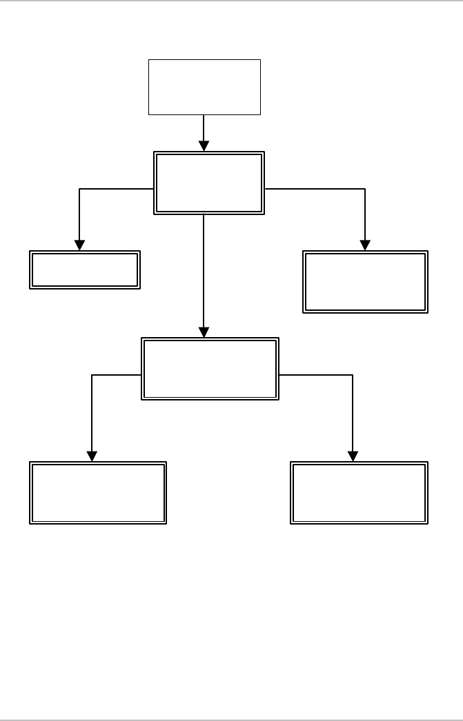
5 Flowcharts
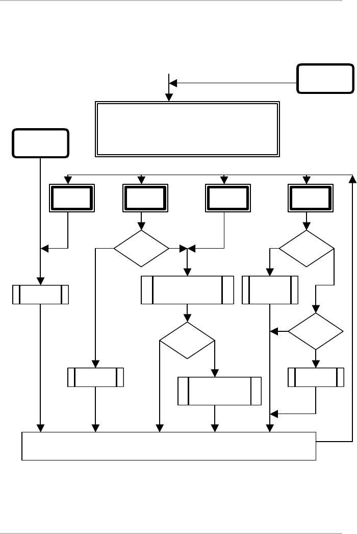
5.1 Normal Mode
Read
button
Write
button
Verify
button
Reset
button
Reticle SMIF Pod Read/Write Station
by HERMOS Informatik GmbH
Software Version: 1.3
update display
No
Yes
Power up
Event:
Remove pod
Event:
Place pod
barcode
read?
press
long?
Verify
button?
verify
button?
No
Yes
read 1. label /
read 2. label /
read 3. label
No
Yes
verify data
(BC labels / RF tag)
clear
buffers
clear buffer
and RF tag
Yes
No
write data to
RF tag
read data
from RF tag
Software Reticle Read – Write Station – Stand Alone
Technical Reports, Release 1.1
Page 11 of 15
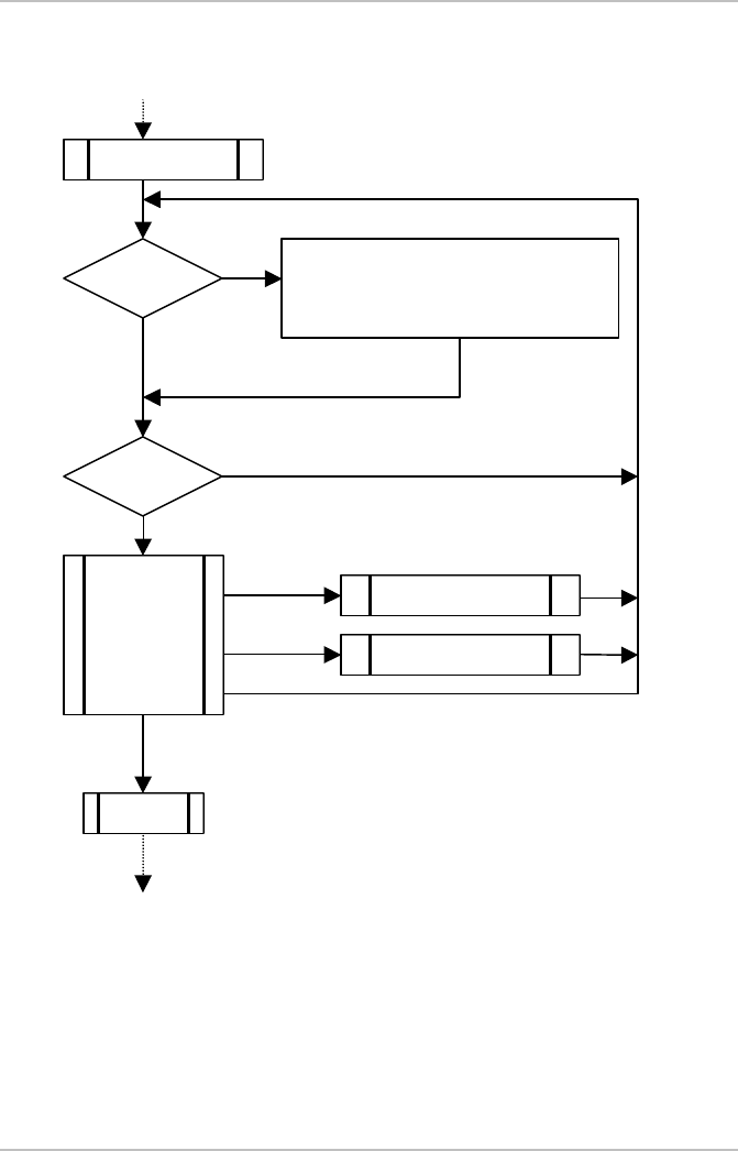
5.2 17 Page Mode
Press the ‘Reset’ button or remove pod to leave this state.
Use the ‘Read’ and ‘Write’ button to scroll the pages (step: 3 pages)
Do you want to enter 17 page state?
READ = Yes | WRITE = No
choose display format
READ = ASCII | WRITE = HEX
B:1|2|3|4|5|6|7|8|L
P01:0|0|9|0|0|6|3|0|
P02:0|0|0|0|0|0|0|0|
P03:1|X|3|0|S|A| | |
B:1 |2 |3 |4 |5 |6 |7 |8 |L
P01:30|30|39|30|30|36|33|30|
P02:30|30|30|30|30|30|30|30|
P03:31|58|33|30|53|41|00|00|
Enter 17 page mode
with Verify button
long
back to normal
operation / reading
POD
HEX
ASCII
No
Yes
Software Reticle Read – Write Station – Stand Alone
Technical Reports, Release 1.1
Page 12 of 15
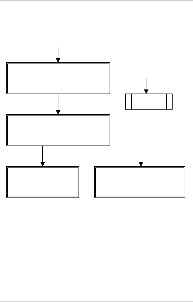
5.3 Menu Mode
Press the ‘Verify’ button for more than 3 seconds to save the parameters!
Press the ‘Reset’ button to leave the current menu level and return to the parent
menu level or to leave the menu.
Main menu
Display
Parameter
Download
Download Display Menu
-------------------
DSP bright up
DSP bright down
Parameter Menu
Filler
Reader Parameter
Not used
Display select
Download select
Parameter select
Menu Parameter
Sensor delay : 05
Blank byte : 00
Menu Filler
Product : 00
Layer : 00
CID : 0
Filler select
Reader
Parameter select
Enter menu with
Verify and Reset
b
utton long
(no pod present)
Software Reticle Read – Write Station – Stand Alone
Technical Reports, Release 1.1
Page 13 of 15
5.4 Brightness Mode
Display Menu | Read = up
----------------- | Write = down
DSP bright up | Reset = ESC
DSP bright down |
Verify button
DSP
changed?
select DSP bright up
DSP brightness + 1 step
select DSP bright down
DSP brightness - 1 step
switch button:
READ
WRITE
VERIFY
RESET
yes
no
key
pressed?
no
yes
Read button
Write button
Reset button
exit display
menu
Verify button to enter
Display menu
Software Reticle Read – Write Station – Stand Alone
Technical Reports, Release 1.1
Page 14 of 15
6 ASCII table
Dec Hex Ctrl Code Dec Hex Char
0 00 ^@ NUL 32 20
1 01 ^Â SOH 33 21 !
2 02 ^B STX 34 22 “
3 03 ^C ETX 35 23 #
4 04 ^D EOT 36 24 $
5 05 ^E ENQ 37 25 %
6 06 ^F ACK 38 26 &
7 07 ^G BEL 39 27 ‘
8 08 ^H BS 40 28 (
9 09 ^I HT 41 29 )
10 0A ^J LF 42 2A *
11 0B ^K VT 43 2B +
12 0C ^L FF 44 2C ,
13 0D ^M CR 45 2D -
14 0E ^N SO 46 2E .
15 0F ^O SI 47 2F /
16 10 ^P DLE 48 30 0
17 11 ^Q DC1 49 31 1
18 12 ^R DC2 50 32 2
19 13 ^S DC3 51 33 3
20 14 ^T DC4 52 34 4
21 15 ^U NAK 53 35 5
22 16 ^V SYN 54 36 6
23 17 ^W ETB 55 37 7
24 18 ^X CAN 56 38 8
25 19 ^Y EM 57 39 9
26 1A ^Z SUB 58 3A :
27 1B ^[ ESC 59 3B ;
28 1C ^\ FS 60 3C <
29 1D ^] GS 61 3D =
30 1E ^^ RS 62 3E >
31 1F ^_ US 63 3F ?
Software Reticle Read – Write Station – Stand Alone
Technical Reports, Release 1.1
Page 15 of 15
Dec Hex Char Dec Hex Char
64 40 @ 96 60 `
65 41 A 97 61 a
66 42 B 98 62 b
67 43 C 99 63 c
68 44 D 100 64 d
69 45 E 101 65 e
70 46 F 102 66 f
71 47 G 103 67 g
72 48 H 104 68 h
73 49 I 105 69 I
74 4A J 106 6A j
75 4B K 107 6B k
76 4C L 108 6C l
77 4D M 109 6D m
78 4E N 110 6E n
79 4F O 111 6F o
80 50 P 112 70 p
81 51 Q 113 71 q
82 52 R 114 72 r
83 53 S 115 73 s
84 54 T 116 74 t
85 55 U 117 75 u
86 56 V 118 76 v
87 57 W 119 77 w
88 58 X 120 78 x
89 59 Y 121 79 y
90 5A Z 122 7A z
91 5B [ 123 7B {
92 5C \ 124 7C |
93 5D ] 125 7D }
94 5E ^ 126 7E ~
95 5F _ 127 7F DEL
HERMOS Informatik GmbH Tel. +49-9279/991-910
Gartenstrasse 19, D-95490 Mistelgau Fax +49-9279/991-900