Brooks Automation TLG Transponder Reader System User Manual A5 E 2 2
Brooks Automation (Germany) GmbH RFID Division Transponder Reader System A5 E 2 2
Users manual
Page 1 of 22
2000-01-11
Release 2.2
LON Transponder Reader
Technical Reports

Hermos Technical Reports
Release 2.1 Page 2 of 22
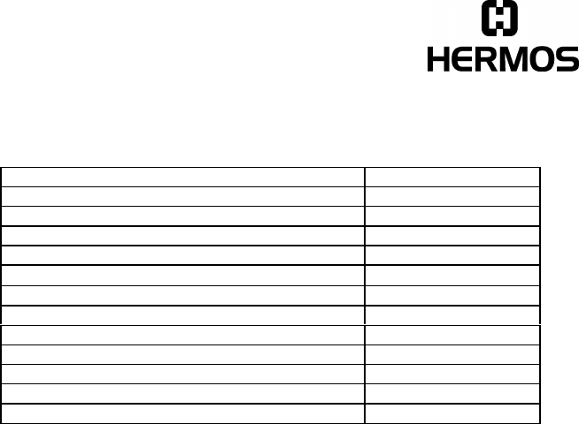
1SYSTEM DESCRIPTION 3
2IMPORTANT NOTES: 4
3HARDWARE 5
3.1 CONSTRUCTION 5
3.2 STANDARD HOUSING 7
3.3 TERMINAL CONNECTION 8
4TECHNICAL DATA 10
4.1 POWER SUPPLY AND CURRENT INPUT 11
4.2 ADDITIONAL INSTRUCTION FOR USE 11
5INSTALLATION DESCRIPTION OF THE LON-NETWORK 12
5.1 TRANSMISSION MEDIUM 12
5.2 NETWORK TOPOLOGY 12
6LICENSES AND CERTIFCATES 14
7WARRANTY AND LIABILITY 15
8READING AND WRITING RANGES 16
8.1 READING RANGE STICK ANTENNA 16
8.2 WRITING RANGE STICK ANTENNA 17
8.3 READING RANGE MICRO ANTENNA 18
8.4 WRITING RANGE MICRO ANTENNA 19
8.5 READING RANGE FRAME ANTENNA 20
8.6 WRITING RANGE FRAME ANTENNA 21
9ACCESSORIES 22
9.1 CABLING OF POWER AND LON 22
9.2 CONNECTION OF THE EXTERNAL SENSOR/ACTOR 22
9.3 POWER SUPPLY 22

Hermos Technical Reports
Release 2.1 Page 3 of 22
1 System Description
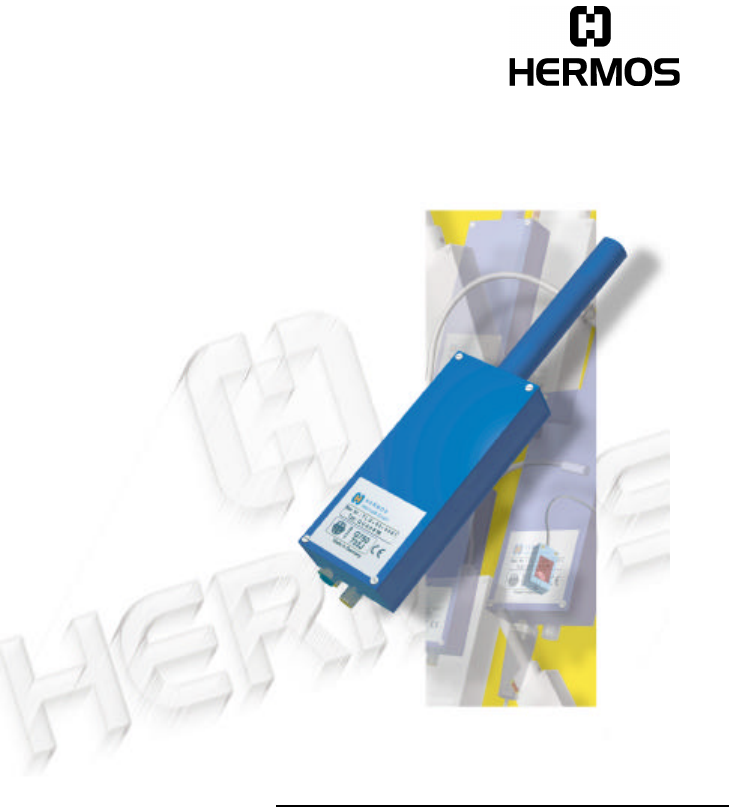
The HERMOS transponder reader system is used in the semiconductor industry for
the identification of the wafer-carrier. It is a high frequency identification system
using the FM-transmission.
The basic item is a transponder working as a forgery-proof electronic identity disc.
The reader of the system sends an energy impulse via the antenna. The capacitor
of the passive, battery-less transponder is charged by this impulse. After that, the
transponder returns a signal with the stored data.
The total reading cycle takes less than 100 ms.
As a sight-connection between transponder and reader is not absolutely necessary,
the transponder can also be identified through non-metallic material.
The HERMOS transponder reading unit is a LON-node. LON is a control network
for distributed systems and has been developed by the US company Echelon. The
LONWORKS-technology corresponds to the SEMI (Semiconductor Equipment
Materials International)-Standard (E54.6).
The data received by the transponder reader are transmitted to equipment,
terminalserver or host systems by the LON-network.

Hermos Technical Reports
Release 2.1 Page 4 of 22
2 Important Notes:
This device complies with Part 15 of the FCC Rules. Operation is subject to the
following two conditions:
1) this device may not cause harmful interference , and
2) this device must accept any interference received, including interference that
may cause undesired operation.
CAUTION:
Changes or modifications not expressly approved by the party responsible for
compliance could void the user’s authority to operate the equipment.
NOTE:
This equipment has been tested and found to comply with the limits for a Class B
digital device, pursuant to part 15 of the FCC Rules. These limits are designed to
provide reasonable protection against harmful interference in a residential
installation.
This equipment generates, uses and can radiate radio frequency energy and, if not
installed and used in accordance with the instructions,may cause harmful
interference to radio communications. However, there is no guarantee that
interference will not occur in a particular installation. If this equip-ment does cause
harmful interference to radio or television reception, which can be determined by
turning the equipment off and on, the user is encouraged to try to correct the
interference by one or more of the following measures:
—Reorient or relocate the receiving antenna.
—Increase the separation between the equip-ment and receiver.
—Connect the equipment into an outlet on a circuit different from that to
which the receiver is connected.
—Consult the dealer or an experienced radio/TV technician for help.
Hermos Technical Reports
Release 2.1 Page 5 of 22
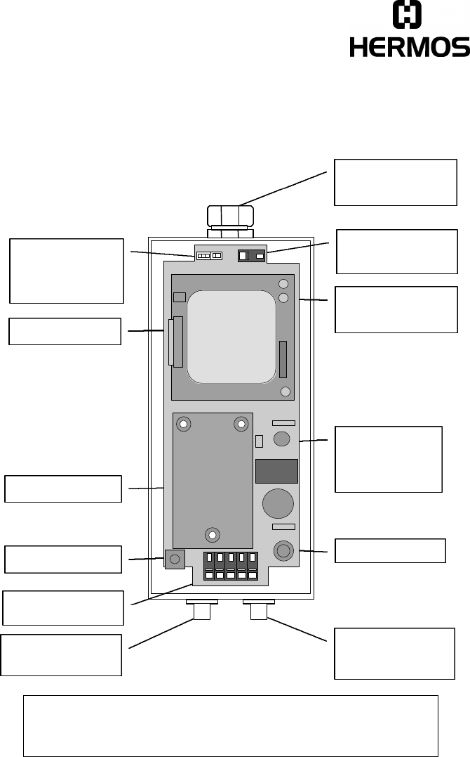
3 Hardware
3.1 Construction
SERVICE-key Fuse
Control-LED
red:SERVICE
green: READ
Control-module
Connection
terminal
Screw connection
for antenna
Shield connection
for antenna lead
HF-module
External input and
output
Attention:
ALL ANTENNA RESONANT CIRCUIT COMPONENTS CAN CARRY HIGH
VOLTAGE!
Connection for ext.
input and output
Conncection for
power and LON-
bus
Output for antenna
C C S - +
S
XS1 XS2

Hermos Technical Reports
Release 2.1 Page 6 of 22
Control-LED
The two-coloured control-LED (red/green) shows the actual operation status of the
device.
Red: The control-LED glows shortly red, if the SERVICE-button had been pushed.
If the LED blinks red or glows red continuously, the device is unconfigured or
applicationless. In this case, please contact the manufacturer.
Green: The control-LED glows shortly green, if the device tries to read or write.
SERVICE-button
The SERVICE-button can be used to install the reader into the network.
Terminal screw for antenna shielding
The shield of the antenna has to be sticked on the terminal screw.
Control-module
The control-module is the control unit of the device. On the module, there is the
controller (Neuron-chip), a plug-in program memory (FlashEEPROM) and the
FTT10-A transceiver for the communication on the LON-bus.
HF-module
The HF-module is the analog part of the device. It triggers the antenna and
transmits the received data to the control-module.
Hermos Technical Reports
Release 2.1 Page 7 of 22
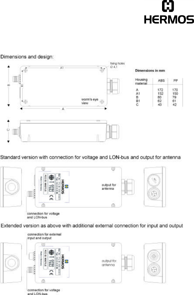
3.2 Standard Housing
Hermos Technical Reports
Release 2.1 Page 8 of 22
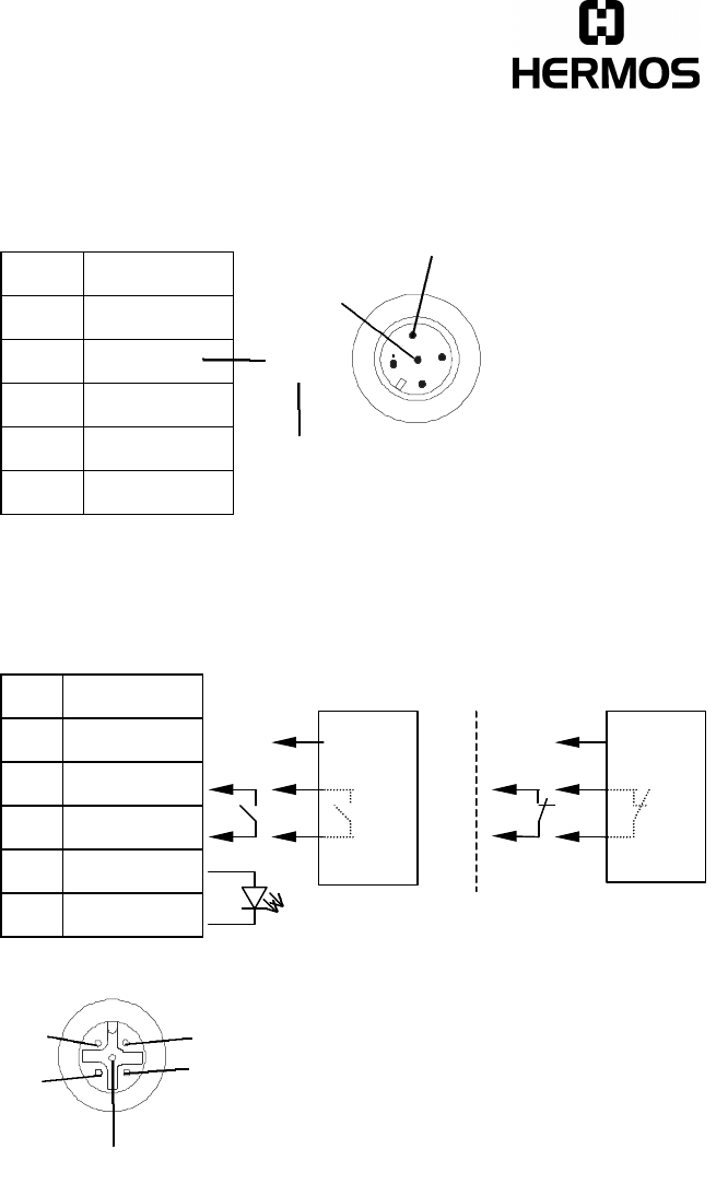
3.3 Terminal Connection
Built-in male plug, plastic (supply and LON)
PIN signal
1+24V
20V
3LON
4LON
5shield
Up to serial-no. TLG-00-1999: Pin 5 (shield) has to be connected!
Option: built-in female plug, metal (external sensor/actor)
PIN signal
1+24V Output
20V
3IN NPN
4+5V
5OUT LED
1
2
3
4
5
Sensor is not connected.
3
4
5
12
positive logic negative logic
+ 10..30V
DC
0 V
Type: NPN
Output Q
+ 10..30V
DC
0 V
Type: NPN
Output Q
Please advise in your order which
sensor logic will be used!

Hermos Technical Reports
Release 2.1 Page 9 of 22
For the actor signal a LED without a shunt (connection to PIN 4 and 5) is required.
For the sensor a potential free contact (connection to PIN 2 and 3) or a 24V-
sensor (3 wire version with npn-output, connection to PIN 1 to 3) is required.
Important:
Up to serial-no: TLG-00-1999
For devices which have been delivered before the end of November 1998,
please pay attention to the following when selecting the 24V-sensor:
In open wiring condition, maximally +5V may be applied to the npn-output!
Hermos Technical Reports
Release 2.1 Page 10 of 22
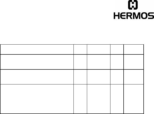
4 Technical Data
Parameter Value
Operation temperature 0 to +50°C
Stock temperature -25 to +70 °C
Permissible humidity @ 50C° 25 - 80 %
Transmitter frequency 134.2 kHz
Max. transmitting level in 3m distance 104 dBµV/m
Typ. period of charging impulse 50ms
Max. repeat of reading 4/s
Max. repeat of program 1/s
Protection mode IP 40
Housing ABS or PP
Weight (with rod antenna and presence sensor) about 440g
Fuse type TR4 500mA (T)
Hermos Technical Reports
Release 2.1 Page 11 of 22
4.1 Power Supply and Current Input
Description min type max unit
Voltage (proof against connecting to
the wrong terminal) 18 24 30 VDC
Current with/without presence sensor
(starting process excluded) 30 / 55 mA
Reading/writing impulse
rod antenna without/with presence
sensor
micro antenna without/with presence
sensor
160 / 185
140 / 165
mA
mA
Remark to the power supply:
During the starting process (charging of the capacitor in the input filter of the
device), you have to ensure that the power supply does not cut off the output
current. We recommend to use a power supply with stable current characteristic
up to 0V output voltage (for example our part-no. SVG2,5).
4.2 Additional Instruction for Use
Never expose the device to a intense change in temperature. Otherwise, water of
condensation can develop inside the device what can lead to damages.
Never bend or extend the antenna cable or expose it to other mechanical loads.
Hermos Technical Reports
Release 2.1 Page 12 of 22
5 Installation Description of the LON-Network
The installation can be carried out with the cables and distributors pre-manu-
factured by HERMOS (see 6. Accessories). Your own cabling is also possible
when the following points are noticed.
5.1 Transmission Medium
The bus cable is realized through an economy-priced twisted pair cable. With
carried along operation voltage with 4 cores.
For shielded cables, the shield has to be connected on both sides.
Realization with optical fibre, radio and infrared is also possible.
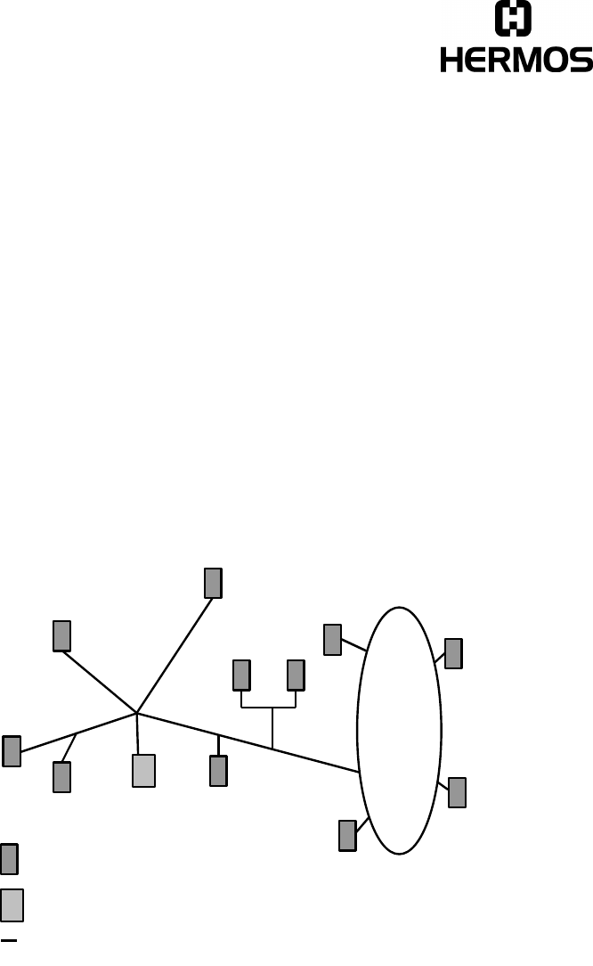
5.2 Network Topology
There are two possiblities of network topology:
-Free topology
-Bus-topology
The free topology allows a constellation in line-, star, ring- or tree-structure.
So it is able to correspond to the geometrical demands.
A mixed architecture is also possible.
Only one connector is required.
On account of the mode of transmission, it cannot be connected the wrong way
round.
T
Reader or gateway
Terminator (bus termination
Connection cable (bus + power supply)
T
Hermos Technical Reports
Release 2.1 Page 13 of 22
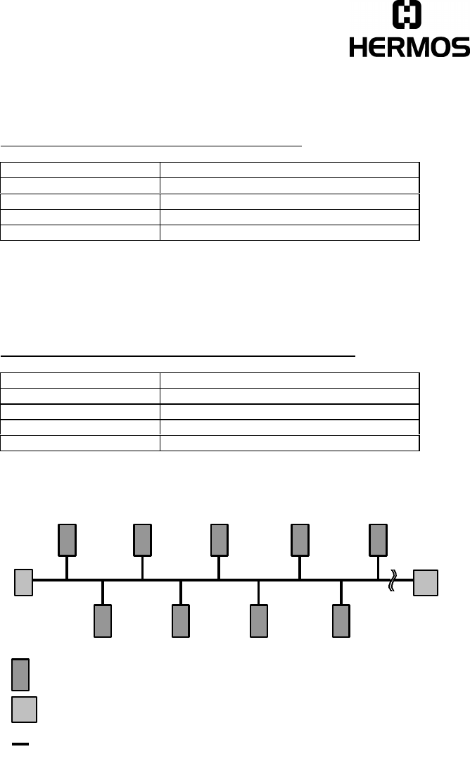
In the standard version, the devices are equipped with a FFT-10A transceiver.
For the transceiver FTT-10 following data are applied:
Cable type Max. length of node to node
Belden 85102 500m
Belden 8471 400m
Level IV, 22AWG 400m
JY (St) Y 2x2x0,8 320m
The bus-topology consists of a main cable on which the individual nodes will be
connected with short stub lines. Terminators have to be connected on both ends of
the cable.
For the transceivers FTT-10 following bus lengthes are applied:
Cable type Max. length of main cable
Belden 85102 2700m
Belden 8471 2700m
Level IV, 22AWG 1400m
JY (St) Y 2x2x0,8 900m
The maximal length of a stub line is 3m.
T T
Reader or gateway
Terminator (bus termination)
Connection cable (bus + power supply)
T

Hermos Technical Reports
Release 2.1 Page 14 of 22
6 Licenses and Certifcates
• BZT Number: G750733J
• EC-Type Certification Registration Number: B132424J
• FCC ID: N5GTLG

Hermos Technical Reports
Release 2.1 Page 15 of 22
7 Warranty and Liability
The warranty period is 6 months and starts with the moment of the delivery of the
device which has to be proved by invoice or other documents.
The warranty includes the repair of all damages of the device, occurring within the
warranty period, which are evidently caused by faults of the material or productional
defects.
Not included into the warranty are damages caused by not prescribed connection,
inappropriate handling and non-observance of the technical reports.
Hermos Technical Reports
Release 2.1 Page 16 of 22
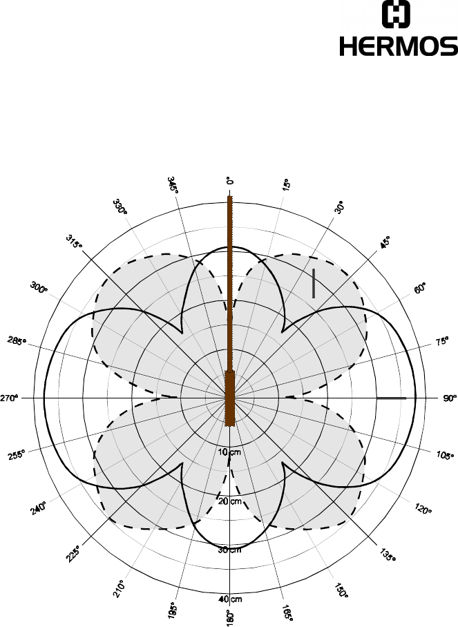
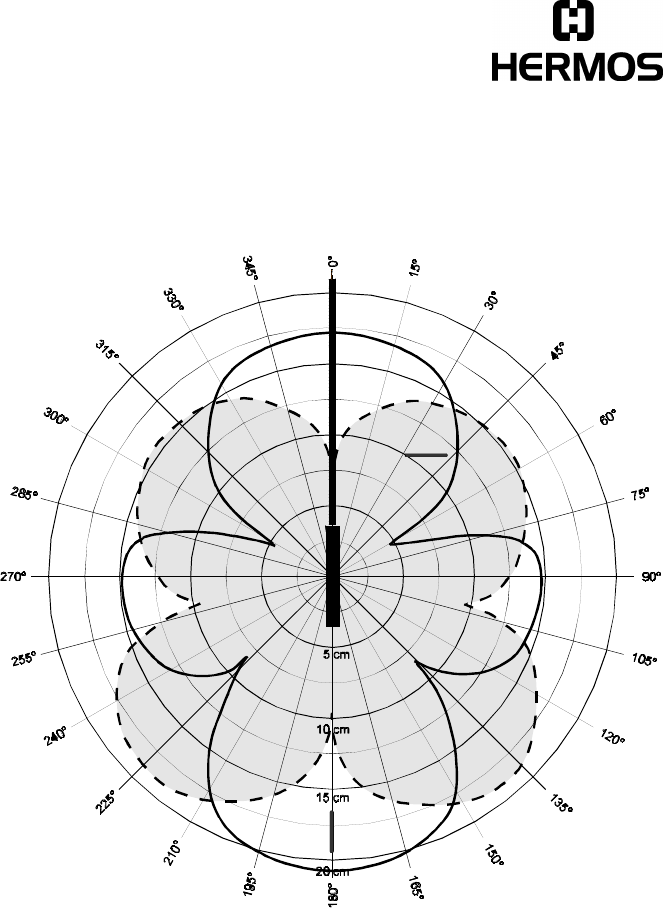
8 Reading and Writing Ranges
These diagrams have been taken at optimal conditions.
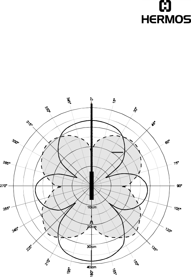
8.1 Reading Range Stick Antenna
Transponder: 32 mm multipage glass transponder
Antenna: HERMOS stick antenna
________ Transponder parallel to antenna
- - - - - - - - Transponder 90° to antenna
Hermos Technical Reports
Release 2.1 Page 17 of 22
8.2 Writing Range Stick Antenna
Transponder: 32 mm multipage glass transponder
Antenna: HERMOS stick antenna
________ Transponder parallel to antenna
- - - - - - - - Transponder 90° to antenna
Hermos Technical Reports
Release 2.1 Page 18 of 22
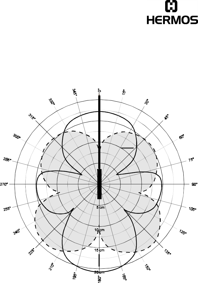
8.3 Reading Range Micro Antenna
Transponder: 32 mm multipage glass transponder
Antenna: HERMOS micro antenna
________ Transponder parallel to antenna
- - - - - - - - Transponder 90° to antenna
Hermos Technical Reports
Release 2.1 Page 19 of 22
8.4 Writing Range Micro Antenna
Transponder: 32 mm multipage glass transponder
Antenna: HERMOS micro antenna
________ Transponder parallel to antenna
- - - - - - - - Transponder 90° to antenna
Hermos Technical Reports
Release 2.1 Page 20 of 22
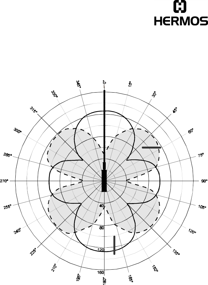
8.5 Reading Range Frame Antenna
Transponder: 32 mm multipage glass transponder
Antenna: HERMOS frame antenna
________ Transponder parallel to antenna
- - - - - - - - Transponder 90° to antenna
Hermos Technical Reports
Release 2.1 Page 21 of 22
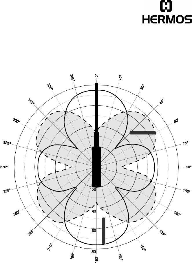
8.6 Writing Range Frame Antenna
Transponder: 32 mm multipage glass transponder
Antenna: HERMOS frame antenna
________ Transponder parallel to antenna
- - - - - - - - Transponder 90° to antenna
Hermos Technical Reports
Release 2.1 Page 22 of 22
9 Accessories
9.1 Cabling of Power and LON
• Female plug, straight : KBV-GK
• Female plug, angled : KBV-WK
• Male plug, straight : KSS-GK
• Current connector with two cores: KBV24
• Bus-cable connector with two male plugs, 0.2m : KVSS02
• Bus-cable with two female plugs (0.5m, 1m, 2m, 4m, 6m, 8m, 10m) :
BZK05, BZK10, BZK20, BZK40, BZK60, BZK80, BZK100
• Y-cable: one female plug, two male plugs : YKB2KS
• Bus-cable with 1 female plug (0.5m, 1m, 2m, 4m, 6m, 8m, 10m) :
BEK05, BEK10, BEK20, BEK40, BEK60, BEK80, BEK100
9.2 Connection of the external Sensor/Actor
• Male plug, metal : KSS-GM
• Angled male plug, metal : KSS-WM
• External optical coupler for top-hat rail installation (can be connected directly on
the LED, output data: 48V DC 100mA ) : LDOP
9.3 Power Supply
• Power supply, input: AC 120-230 V, output: DC 24 V / 2.5 A:
SVG2,5
• Power supply, input: AC 120-230 V, output: DC 24 V / 4 A:
SVG4
Hermos Informatik GmbH Tel. +49-9279/991-910
Gartenstrasse 19, D-95490 Mistelgau Fax +49-9279/991-900