Brooks Automation TSG Inductive TAG System User Manual RS232 A5 E 0 3 SECS1
Brooks Automation (Germany) GmbH RFID Division Inductive TAG System RS232 A5 E 0 3 SECS1
UserManual.wiki
>
Brooks Automation
>
TSG User Manual
Users Manual
Navigation menu
Upload a User Manual
Namespaces
Wiki Guide
HTML
PDF
Info
Views
User Manual
Discussion / Help
Navigation


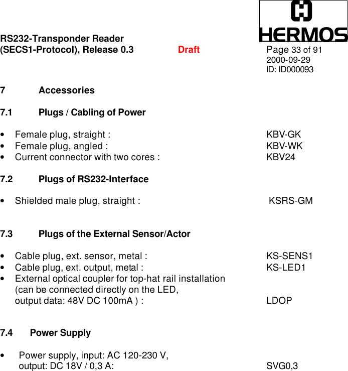
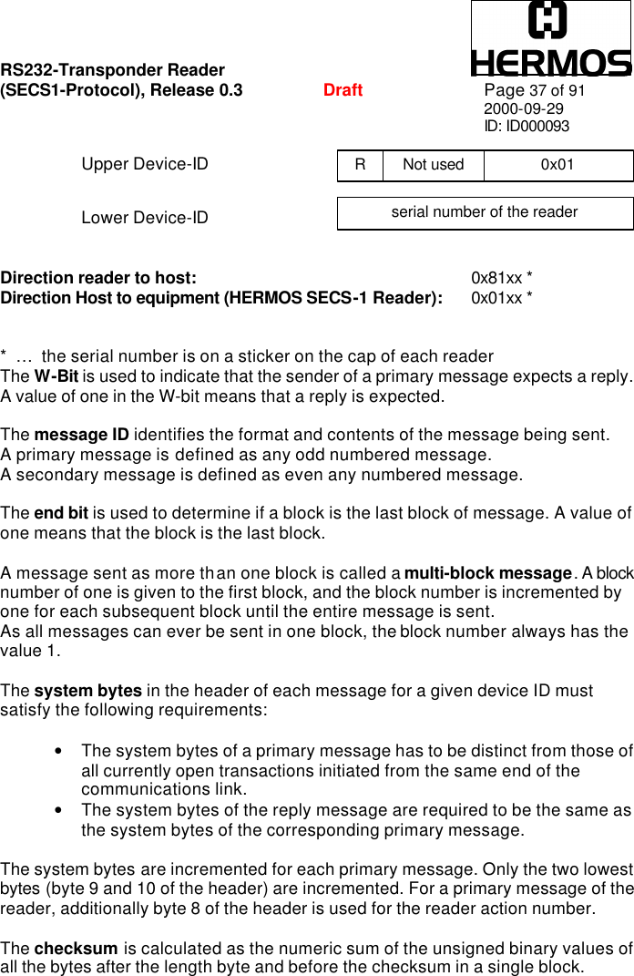
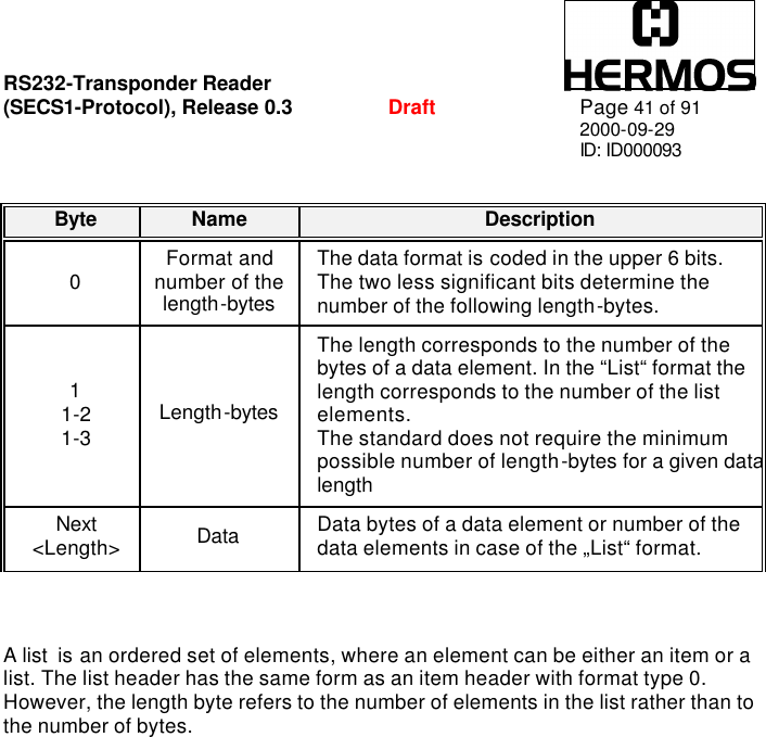
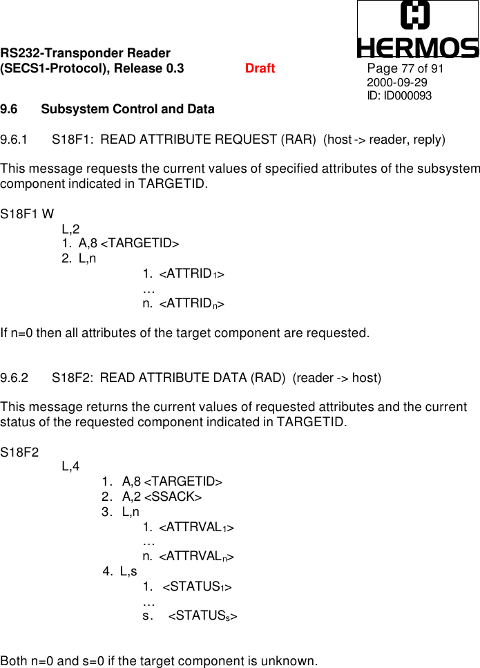
![RS232-Transponder Reader (SECS1-Protocol), Release 0.3 Draft Page 42 of 91 2000-09-29 ID: ID000093 8.2.2 Data Items: The formats represent arrays of types: <type>[number of elements] where <type> is one of the following: Data items examples: Oct-Code Hex-Code Format Meaning Example 00 01 List List element with the number of the „Length“ data elements <L2> <A “Hello“> <B 0x00> 11 25 Boolean 1 – Byte Boolean false = 00 ; true != 00 <I1 123> 10 21 Binary Byte sequence of the length „Length“ <I1 123> 20 41 Ascii Printable Ascii signs 31 65 I1 1 - Byte signed Integer <I1 123> 32 69 I2 2 - Byte signed Integer <I2 –12345> 34 71 I4 4 - Byte signed Integer <I4 2147483647> 30 61 I8 8 - Byte signed Integer <I8 –931372980293834> 51 A5 U1 1 - Byte unsigned Integer <U1 0> 52 A9 U2 2 - Byte unsigned Integer <U2 #empty> 54 B1 U4 4 - Byte unsigned Integer <U4 429489725> 50 A1 U8 8 - Byte unsigned Integer <U8 763468676756767> 40 91 F8 8 - Byte floating point <F8 1.223 e204> 44 81 F4 4 - Byte floating point <F4 -1.23 > Meaning Format Length 1- Byte Integer 65 01 xx 4- Byte Integer 71 04 MSB ... ... LSB ASCII 41 06 1.chr 2.chr 3.chr 4.chr 5.chr 6.chr zero-length xx 00 List Data Item 01 03 1. element 2. element 3. element](https://usermanual.wiki/Brooks-Automation/TSG/User-Guide-298198-Page-42.png)
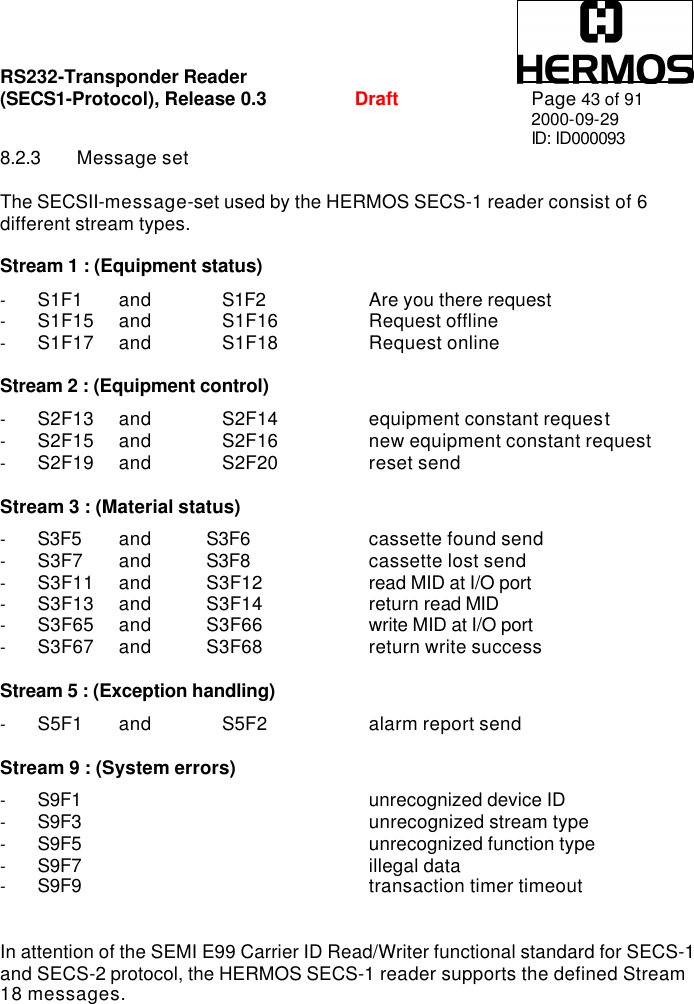
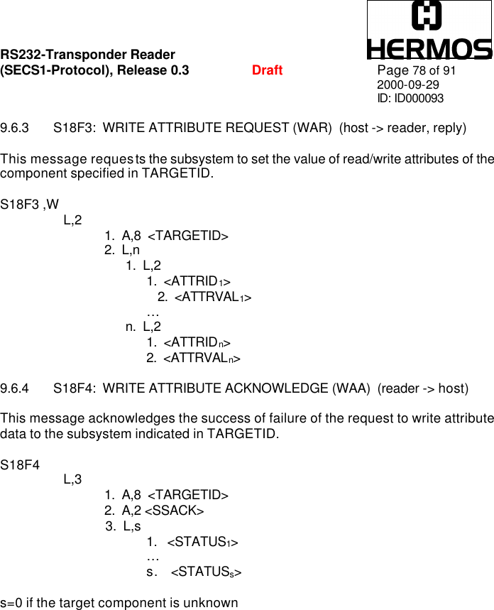
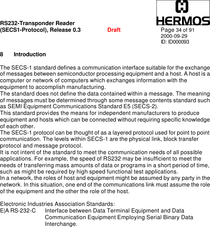
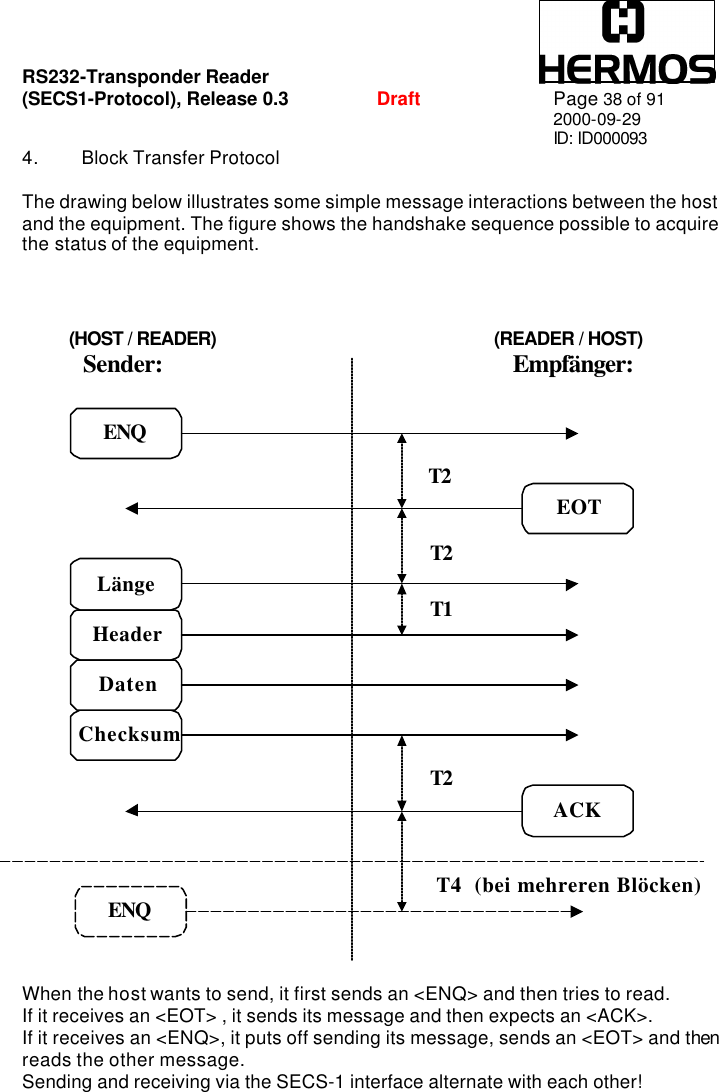
![RS232-Transponder Reader (SECS1-Protocol), Release 0.3 Draft Page 46 of 91 2000-09-29 ID: ID000093 8.2.5 Data Item Dictionary: ACKC3 Format: B[1] Acknowledge Code 0 : Sensor 0 was the initiator 1 : Sensor 1 was the initiator >1 : error, not accepted Where used: S3F6, S3F8 ACKC5 Format: B[1] Acknowledge Code 0 : no error >0 : error, not accepted Where used: S5F2 ALCD Format: B[1] Alarm Code Byte. Only the occurring of a failure is told. Failures will not be reset on principle. Bit 8 = 1 : alarm is set Where used: S5F1](https://usermanual.wiki/Brooks-Automation/TSG/User-Guide-298198-Page-46.png)
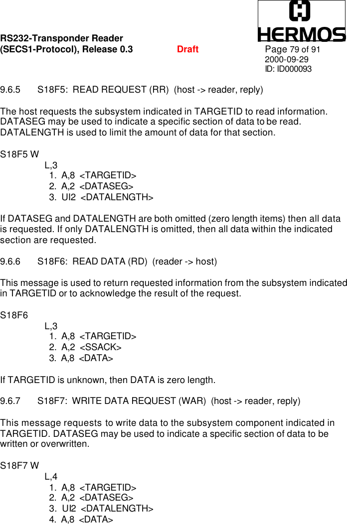
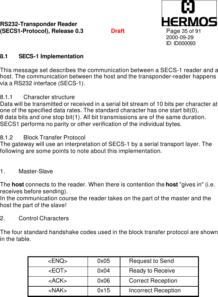
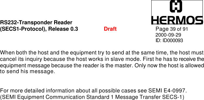
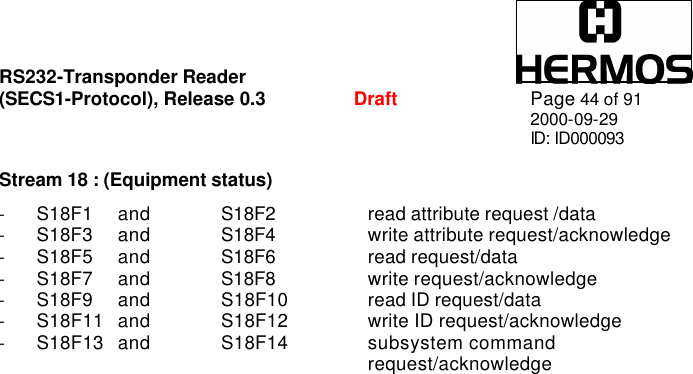
![RS232-Transponder Reader (SECS1-Protocol), Release 0.3 Draft Page 47 of 91 2000-09-29 ID: ID000093 ALID Format: U1[1] Alarm Identifier 0: none error 1: auto read failed, the reader is engaged in doing something 2: reserved 3: reserved 4: no tag could be recognized when the sensor was covered or carrier had been removed prematurely (sensor uncovered!) 5: invalid command or parameter detected 6: unknown error 7: reserved 8: parity- or checksum error detected 9: unexpected confirmation was sent 10: locked page could not write 11: reserved 12: bad type of transponder 13: external read or write failed because the sensor is not covered (no carrier detected) 14: reserved 15: reserved Where used: S5F1 ALTX Format: A[max40] Alarm Text The length of the alarm text is 0 to 40 signs. According to the reader version, state information of the sensor respectively of the sensors are also transmitted during a failure message of the reader. The information has to be interpreted as follows: ALTX[0] Initiator of a failure message “0”: Sensor 0 “1”: Sensor 1 “F”: cannot be assigned](https://usermanual.wiki/Brooks-Automation/TSG/User-Guide-298198-Page-47.png)
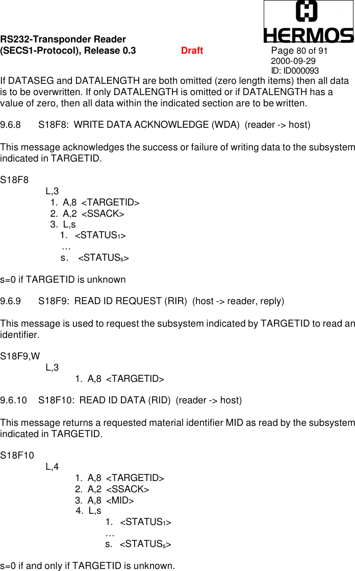
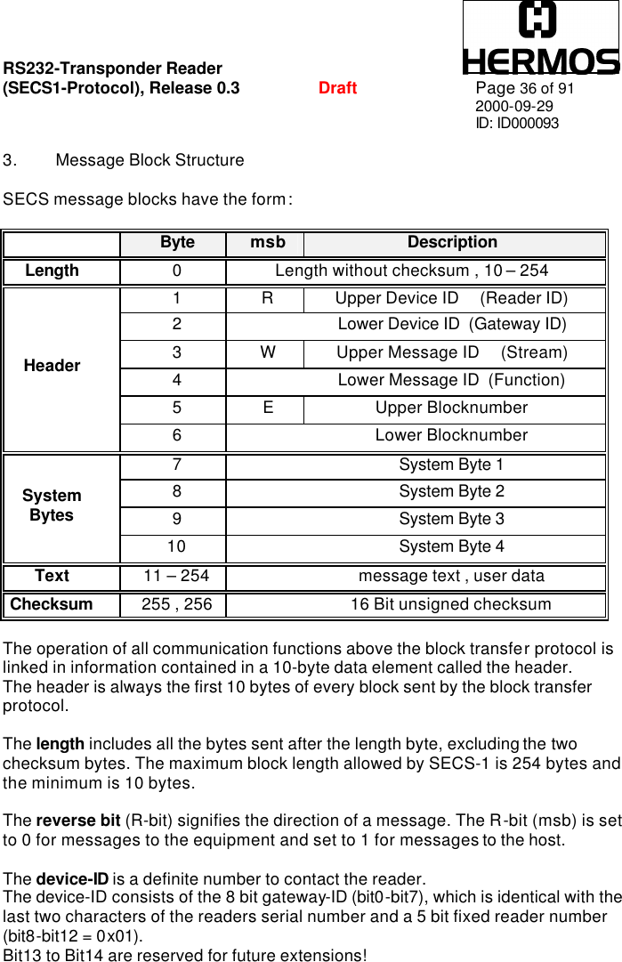
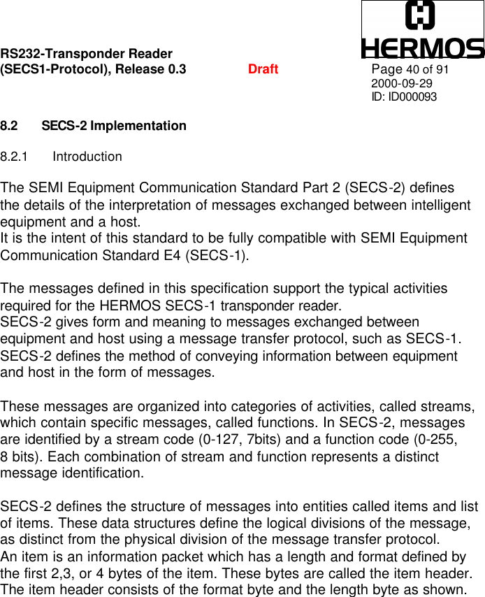
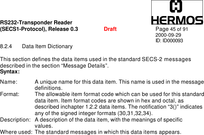
![RS232-Transponder Reader (SECS1-Protocol), Release 0.3 Draft Page 48 of 91 2000-09-29 ID: ID000093 ALTX[1] State of sensor 0 “0”: Sensor not occupied “1”: Sensor is occupied “E”: Sensorstate is not available “F”: Sensor not defined ALTX[2] State of sensor 1 “0”: Sensor not occupied “1”: Sensor is occupied “E”: Sensorstate is not available “F”: Sensor not defined ALTX[3] ‘:’ a colon separates the alarm text from the sensor states Where used: S5F1 ATTRID Format: A[max25] Description: Identifies for an attribute for a specific type of object. CIDRW Attributes definitions: “Configuration”… Number of heads “AlarmStatus” Current CIDRW substate of ALARM STATUS “OperationalStatus” Current CIDRW substate of OPERATIONAL “SoftwareRevisionLevel” Revision (version) of Software 8 byte maximum Head Attribute Definitions: “HeadStatus” The current state “HeadID” Head number 0-31 (2 digits) Where used: S18F1, S18F3](https://usermanual.wiki/Brooks-Automation/TSG/User-Guide-298198-Page-48.png)
![RS232-Transponder Reader (SECS1-Protocol), Release 0.3 Draft Page 49 of 91 2000-09-29 ID: ID000093 ATTRVAL Format: A[max4] Description: Value of the specified attribute. CIDRW Attributes definitions: “Configuration” Number of heads “01” “AlarmStatus” Current CIDRW substate of ALARM STATUS “0” … NO “1” … ALARMS “OperationalStatus” Current CIDRW substate of OPERATIONAL “IDLE” … reader in IDLE mode “BUSY” … reader is busy “MANT” … maintenance mode “SoftwareRevisionLevel” Revision (version) of Software 8 byte maximum Head Attribute Definitions: “HeadStatus” The current state “IDLE” … reader in IDLE mode “BUSY” … reader is busy “NOOP” … not operating “HeadID” Head number 0-31 (2 digits) “00” … Reader 0 “31” … Reader 31 Where used: S18F1, S18F3 CPVAL Format: A[max2] Description: State request value. “OP” … operating state “MT” … maintenance state Where used: S18F13](https://usermanual.wiki/Brooks-Automation/TSG/User-Guide-298198-Page-49.png)
![RS232-Transponder Reader (SECS1-Protocol), Release 0.3 Draft Page 50 of 91 2000-09-29 ID: ID000093 DATA Format: A[max8] Description: A vector or string of unformatted data. The first page (page 1) of each transponder contains the MID. Be careful: A modification of this page would also cause a modification of the MID! Multipage-transponder: DATA area page 2 – page 17 Read/Write-Transponder: DATA correspond to MID Read/Only-Transponder : DATA correspond to MID Where used: S18F6, S18F7 DATALENGTH Format: UI2 Description: Total bytes to be sent. The DATALENGTH corresponds to the quantity of bytes a transponder page consists of. Valid range is from 0x0001 up to 0x0008 Bytes. Where used: S18F5, S18F7 DATASEG Format: A[2] Description: Used to identify the data requested. The DATASEG corresponds to the page number (PAGEID) of multipage-, read/only- and read/write-transponders Multipage-transponder (page 1 up to page 17) : In case of reading only one page of the multipage-transponder, please note the following: “01” : page 1 “81” : locked page 1 ... ... “11” : page 17 “91” : locked page 17 Read/Only-Transponder : “F0” : read only the one page Read/Write-Transponder: “F1” : read or write only the one page Where used: S18F5, S18F7](https://usermanual.wiki/Brooks-Automation/TSG/User-Guide-298198-Page-50.png)
![RS232-Transponder Reader (SECS1-Protocol), Release 0.3 Draft Page 51 of 91 2000-09-29 ID: ID000093 EAC Format: B[1] Acknowledge code for new reader constant 0: parameter set successfully 1: parameter could not be set Where used: S2F16 ECID Format U1[1] Parameter number of reader (look data item ECV) Where used: S2F13, S2F15 ECV Format U1[1] Reader parameters definition. The values here are shown as decimal-values! Parameters: Parameter 0: Gateway-ID The gateway-ID is a part of the device-ID. The HERMOS SECS-1 reader works simultaneously as gateway and reader. In the header of a message it is the “lower message ID”. 00 .. 255 default: last two characters of serial number.](https://usermanual.wiki/Brooks-Automation/TSG/User-Guide-298198-Page-51.png)
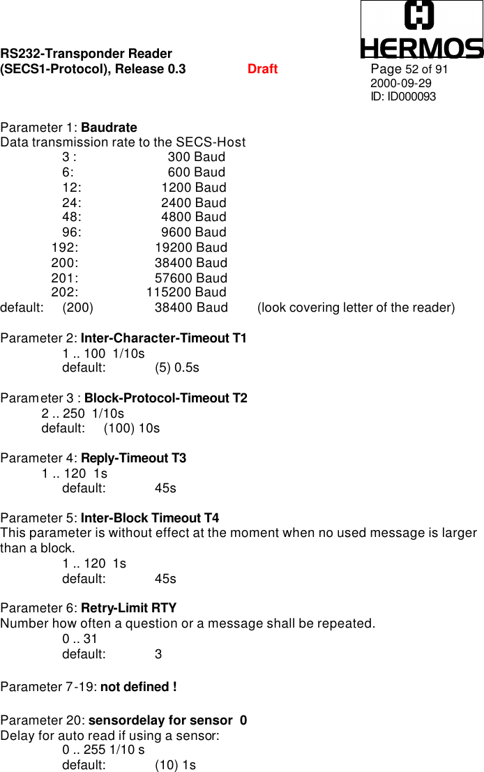
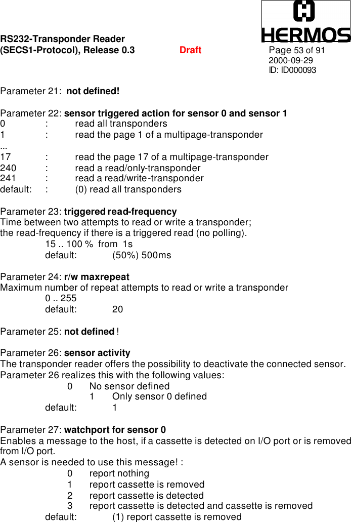
![RS232-Transponder Reader (SECS1-Protocol), Release 0.3 Draft Page 54 of 91 2000-09-29 ID: ID000093 Parameter 28: transmitter-level The intensity of field strength to load a transponder. The default value (1) should not change! 0 reduced field strength 1 maximum field strength default: (1) maximum field strength Parameter 29: transponder load duration The used time to load a transponder. The default value (50ms) should not change! 00 .. 255 ms default: (50) 50ms Parameter 30: not defined ! Parameter 31: not defined ! Parameter 32: not defined ! Parameter 33: automatic environment adjustment The influence of interferences in the environment of the readers can be minimized by an automatic adjustment during the operation. If the automatic adjustment is deactivated, an adjustment to the environment will only be effected in case of a reset. 0: deactivated automatic environment adjustment 1: activated automatic environment adjustment default: (0) deactivated Parameter 34: sensortype for sensor 0 Type of sensor signal to start the auto read if using one sensor: 0: auto read starts if sensor 0 is covered 1: auto read starts if sensor 0 is interrupted default: (0) sensor 0 is covered Where used: S2F13, S2F15 MDLN Format: A[6] Equipment Model Number. Where used: S1F2](https://usermanual.wiki/Brooks-Automation/TSG/User-Guide-298198-Page-54.png)
![RS232-Transponder Reader (SECS1-Protocol), Release 0.3 Draft Page 55 of 91 2000-09-29 ID: ID000093 MF Format: B[1] Material format code. 20: The material port number corresponds to the sensor number and state Where used: S3F5, S3F7 MHEAD Format: B[10] SECS Message Block Header associated with message block in error. Where used: S9F1, S9F3, S9F5, S9F7, S9F9 MID Format: A[max16] Description: Material ID. The MID corresponds to the first page (16 characters from ‘0’…’F’) of the TIRIS transponder. Depend on the transponder- type, it is possible to modify the MID. Multipage-transponder: MID is stored in page 1 (writeable) Read/Write-Transponder: MID correspond to DATA (writeable) Read/Only-Transponder : MID correspond to DATA (fix) Where used: S18F10, S18F11](https://usermanual.wiki/Brooks-Automation/TSG/User-Guide-298198-Page-55.png)
![RS232-Transponder Reader (SECS1-Protocol), Release 0.3 Draft Page 56 of 91 2000-09-29 ID: ID000093 MIDAC Format: B[1] Acknowledge Code 0 : material-ID acknowledged; the sensor 0 was the initiator 1 : not defined 2 : material-ID acknowledged - reaction on externally triggered action; the message cannot be related to any sensor >2 : material-ID not acknowledged The initiator can be determined from the data item Portnumber PTN. Where used: S3F14, S3F68 MIDRA Format: B[1] Material ID acknowledge code 2: acknowledge, will send MID later in S3F13 or S3F67 Where used: S3F12 OBJSPEC Format: A[x] Description: A text string that has an internal format and that is used to point to a specific object instance. The string is formed out of a sequence of formatted substrings, each specifying an object’s type and identifier. The substring format has the following four fields. Object type, colon character ”:” object identifier, greater-than symbol “>” Where the colon character “:” is used to terminate an object type and the greater than symbol “>” is used to terminate an identifier field. The object type field may be omitted where it may be otherwise determined. The final “>” is optional.](https://usermanual.wiki/Brooks-Automation/TSG/User-Guide-298198-Page-56.png)
![RS232-Transponder Reader (SECS1-Protocol), Release 0.3 Draft Page 57 of 91 2000-09-29 ID: ID000093 OFLACK Format: B[1] Acknowledge code for offline request. 0: gateway is offline Where used: S1F16 ONLACK Format: B[1] Acknowledge code for online request. 0: gateway is online Where used: S1F18 PAGE_ID Format: B[1] Page number of multipage-, read/only- and read/write-transponders Multipage-transponder (page 1 up to page 17) : In case of reading only one page of the multipage-transponder, please note the following: 0x01 : (1) page 1 0x81 : (129) locked page 1 ... ... 0x11 : (17) page 17 0x91 : (146) locked page 17 Read/Only-Transponder : 0xF0 : (240) read only the one page Read/Write-Transponder: 0xF1 : (241) read or write only the one page Where used: S3F11](https://usermanual.wiki/Brooks-Automation/TSG/User-Guide-298198-Page-57.png)
![RS232-Transponder Reader (SECS1-Protocol), Release 0.3 Draft Page 58 of 91 2000-09-29 ID: ID000093 PAGEDATA Format: B[9] The cassette identifier that has been read or shall be written. The PAGEDATA corresponds to the value of a transponder page. PAGEDATA [0] corresponds to the page number. The values of the page number (MID[0]) are shown in the data item “PAGE_ID”. PAGEDATA [1] – the 8 byte (one page) of the transponder-ID are following. PAGEDATA [8] Where used: S3F7, S3F12, S3F13, S3F65 PTN Format: B[1] Information about the state of up to 2 sensors and the initiator of the message. For special applications, the reading process of the transponder reader is triggered by 2 sensors. In this case it is necessary to be able to distinguish between the 2 sensors. The initiator represents the number of the sensor which has caused the generation of a message. Default: only sensor 0 is defined! bit 7 ........ bit 0 Initiator Sensor 1 Sensor 0 Sensor 0: bit0 – bit2 The actual state of sensor 0 is described in three bits 0 Sensor not occupied 1 Sensor occupied 7 Sensor not defined Sensor 1: bit3 – bit5 (defined for future developments) The actual state of sensor 1 is described in three bits 0 Sensor not occupied 1 Sensor occupied 7 Sensor not defined](https://usermanual.wiki/Brooks-Automation/TSG/User-Guide-298198-Page-58.png)
![RS232-Transponder Reader (SECS1-Protocol), Release 0.3 Draft Page 59 of 91 2000-09-29 ID: ID000093 Initiator: bit6 – bit7 The initiator represents the number of the sensor which has caused the generation of a message 0 Sensor 0 1 Sensor 1 (not realized at present) 3 cannot be assigned Where used: S3F5, S3F7, S3F12, S3F13, S3F67 RAC Format: B[1] Reset acknowledge code. 0: reset to be done 1: reset could not be done Where used: S2F20 RIC Format: B[1] Reset code. 1: Power up reset 2: Software reset Where used: S2F19 SHEAD Format: B[10] Stored SECS Message Block Header. Only the last message is stored which still has to be confirmed by the Host! Where used: S9F9](https://usermanual.wiki/Brooks-Automation/TSG/User-Guide-298198-Page-59.png)
![RS232-Transponder Reader (SECS1-Protocol), Release 0.3 Draft Page 60 of 91 2000-09-29 ID: ID000093 SSACK Format: A[2] Description: Indicates the success or failure of a requested action. “NO” … normal operation “EE” … execute error “CE” … communication error “HE” … hardware error “TE” … tag error Where used: S18F2, S18F4, S18F6, S18F8, S18F10, S18F12, S18F14 SSCMD Format: A[max18] Description: Indicates an action to be performed by the subsystem. Used to differentiate between different subsystem commands indicated. “ChangeState” … change state “GetStatus” … get state “PerformDiagnostics” … perform diagnostic “Reset” … reset CIDRW Where used: S18F13 STATUS Format: A[2] Description: Provides status information for a subsystem component. “NE” … normal execution “MR” … maintenance required Where used: S18F2, S18F12](https://usermanual.wiki/Brooks-Automation/TSG/User-Guide-298198-Page-60.png)
![RS232-Transponder Reader (SECS1-Protocol), Release 0.3 Draft Page 61 of 91 2000-09-29 ID: ID000093 TARGETID Format: A[max10] Description: Identifies where a request for action or data is to be applied. The text conforms to OBJSPEC. The TARGETID corresponds to the serial number situated on a sticker on top of the reader box Example : “TLG-00-xxxx” (xxxx … dependent on the individual reader) Where used: S18F1, S18F3, S18F5, S18F7, S18F9, S18F11, S18F13](https://usermanual.wiki/Brooks-Automation/TSG/User-Guide-298198-Page-61.png)
![RS232-Transponder Reader (SECS1-Protocol), Release 0.3 Draft Page 66 of 91 2000-09-29 ID: ID000093 9 MESSAGE DETAILS 9.1 Equipment status 9.1.1 S1F0: ABORT TRANSACTION (reader <-> host) Used in lieu of an expected reply to abort a transaction. Function 0 is defined in every stream and has the same meaning in every stream. S1F0 W . * Header Only 9.1.2 S1F1: ARE YOU THERE REQUEST ( reader <-> host, reply ) Establishes if the gateway or host is online. S1F1 W . * Header Only 9.1.3 S1F2: ON-LINE DATA ( host -> reader ) The host signifies that it is online. S1F2 <L[2] <A[6] MDLN > <A[6] SOFTREV > >. 9.1.4 S1F2: ON-LINE ( reader -> host ) The gateway signifies that it is online. S1F2 <L[2] <A[6] MDLN > <A[6] SOFTREV > >. 9.1.5 S1F15: REQUEST OFF_LINE ( host ->reader, reply ) The reader should change the communication state to offline. The reader can only be put online again by message S1F17 (or reset S2F19), and the other messages are aborted by the SxF0 message ! S1F15 W. *Header Only](https://usermanual.wiki/Brooks-Automation/TSG/User-Guide-298198-Page-66.png)
![RS232-Transponder Reader (SECS1-Protocol), Release 0.3 Draft Page 67 of 91 2000-09-29 ID: ID000093 9.1.6 S1F16: OFFLINE ACKNOWLEDGE ( reader -> host ) Acknowledge. S1F16 <B[1] OFLACK>. 9.1.7 S1F17: REQUEST ON_LINE ( host ->reader, reply ) The reader should change the communication state to online. S1F17 W. *Header Only 9.1.8 S1F18: ONLINE ACKNOWLEDGE ( reader -> host ) Acknowledge. S1F18 <B[1] ONLACK>.](https://usermanual.wiki/Brooks-Automation/TSG/User-Guide-298198-Page-67.png)
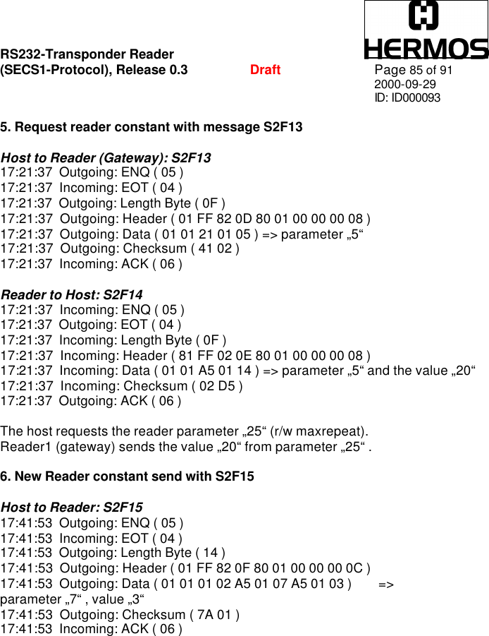
![RS232-Transponder Reader (SECS1-Protocol), Release 0.3 Draft Page 68 of 91 2000-09-29 ID: ID000093 9.2 Equipment Control 9.2.1 S2F0: ABORT TRANSACTION (reader <-> host) Used in lieu of an expected reply to abort a transaction. Function 0 is defined in every stream and has the same meaning in every stream. S2F0 W . * Header Only 9.2.2 S2F13: EQUIPMENT CONSTANT REQUEST (host-> reader , reply) The host requests one constant from the gateway or reader. S2F13 W <L[1] <U1[1] ECID> >. 9.2.3 S2F14: EQUIPMENT CONSTANT DATA (reader -> host ) The reader sends the requested constant to the host. S2F14 <L[1] <U1[1] ECV> >. 9.2.4 S2F15: NEW EQUIPMENT CONSTANT SEND ( host-> reader, reply ) The host changes one reader constant. S2F15 W <L[1] <L[2] <U1[1] ECID> <U1[1]ECV> > >.](https://usermanual.wiki/Brooks-Automation/TSG/User-Guide-298198-Page-68.png)
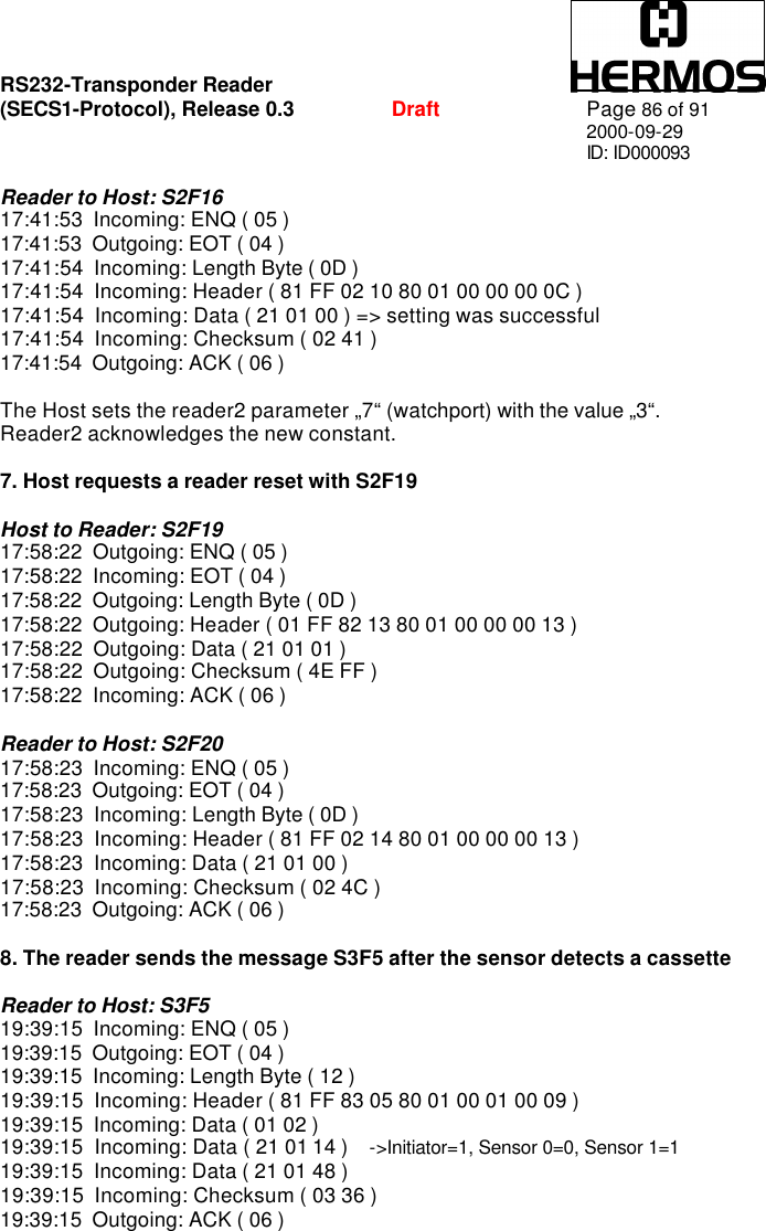
![RS232-Transponder Reader (SECS1-Protocol), Release 0.3 Draft Page 69 of 91 2000-09-29 ID: ID000093 9.2.5 S2F16: NEW EQUIPMENT CONSTANT ACKNOWLEDGE (reader -> host ) The reader acknowledges the new host constant. S2F16 <B[1] EAC>. 9.2.6 S2F19: RESET SEND ( host -> reader, reply ) The host requests the reader to reset the hard- and software. In both cases there will be a communication inquiry with S1F1. The powerup reset requires a few seconds. S2F19 W <B[1] RIC>. 9.2.7 S2F20: RESET ACKNOWLEDGE (reader -> host ) The reader acknowledges the reset. In case of a powerup-reset, the S2F20 message requires a few seconds. S2F20 <B[1] RAC>.](https://usermanual.wiki/Brooks-Automation/TSG/User-Guide-298198-Page-69.png)
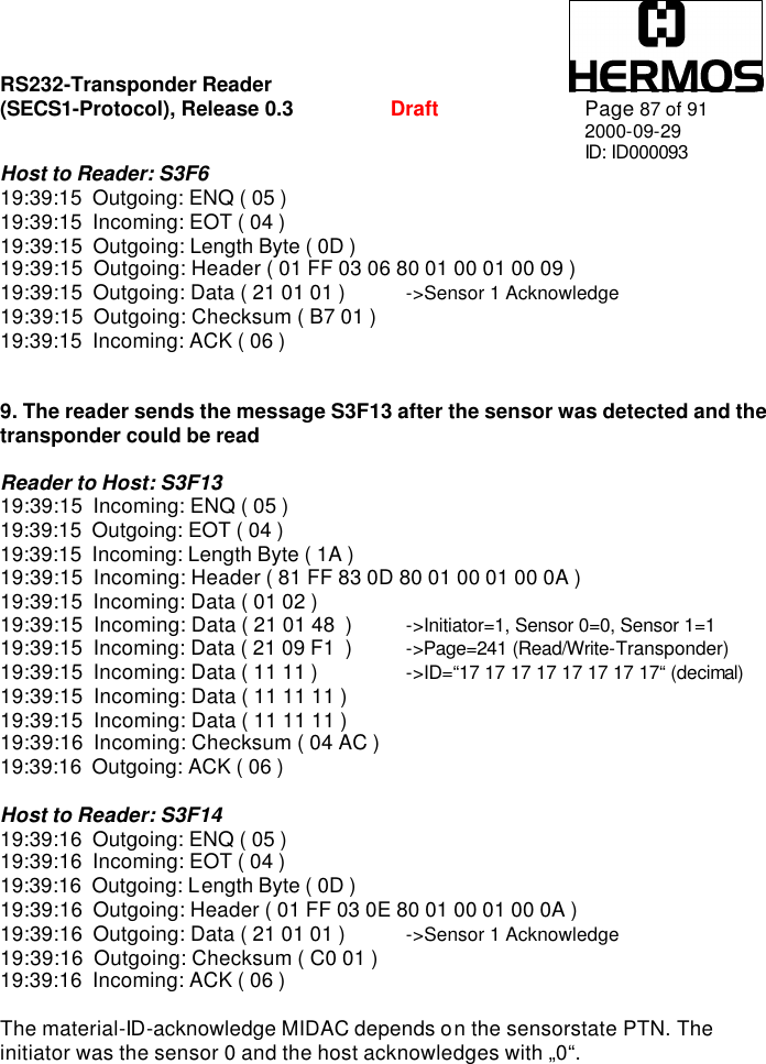
![RS232-Transponder Reader (SECS1-Protocol), Release 0.3 Draft Page 70 of 91 2000-09-29 ID: ID000093 9.3 Material Status 9.3.1 S3F0: ABORT TRANSACTION (reader <-> host) Used in lieu of an expected reply to abort a transaction. Function 0 is defined in every stream and has the same meaning in every stream. S3F0 W . * Header Only 9.3.2 S3F5: CASSETTE FOUND SEND ( reader -> host, reply ) The reader sends the information that a cassette was detected by the sensor. This message will only be sent, if a sensor is connected and activated (see ‘watchport’ and ‘sensor activity’). S3F5 W. <L[2] <B[1] MF> <B[1] PTN> > 9.3.3 S3F6: CASSETTE FOUND ACKNOWLEDGE ( host -> reader) The host acknowledges the cassette found message. S3F6 <B[1] ACKC3>.](https://usermanual.wiki/Brooks-Automation/TSG/User-Guide-298198-Page-70.png)
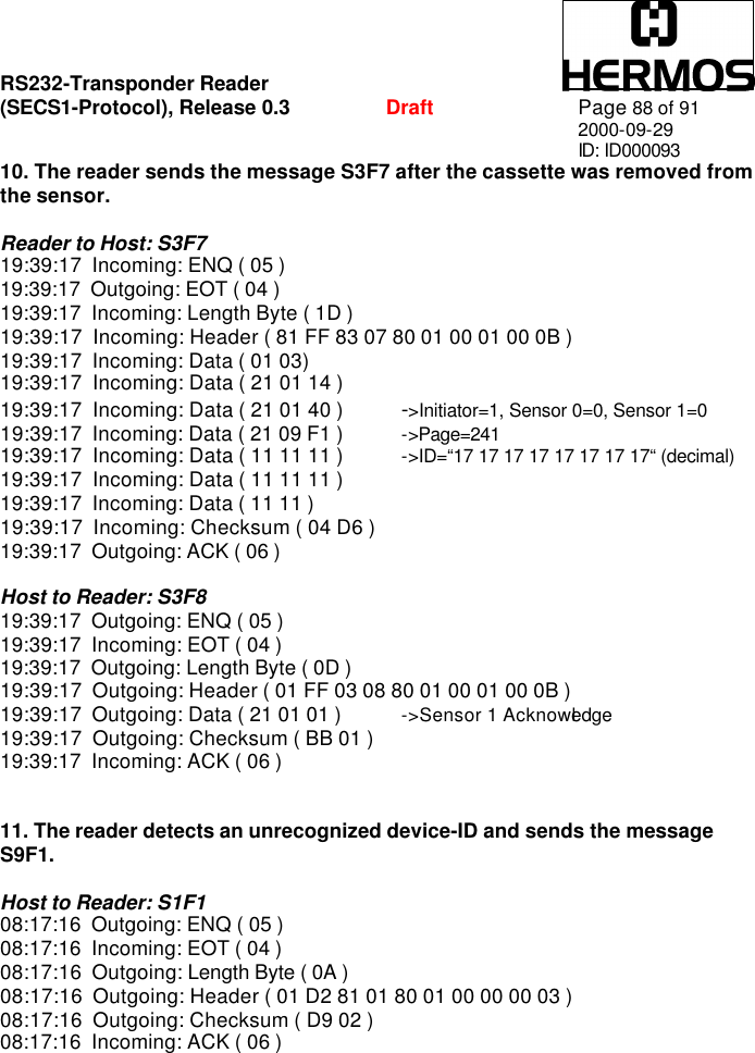
![RS232-Transponder Reader (SECS1-Protocol), Release 0.3 Draft Page 71 of 91 2000-09-29 ID: ID000093 9.3.4 S3F7: CASSETTE LOST SEND ( reader -> host, reply ) The reader sends the information that the cassette was removed from I/O port (sensor). This message will only be sent, if a sensor is connected and activated (see ‘watchport’ and ‘sensor activity’). The PAGEDATA can only be given, if the PAGEDATA read at last is still known. S3F7 W. <L[3] <B[1] MF > <B[1] PTN > <B[9] PAGEDATA > * a zero-length PAGEDATA indicates that no PAGEDATA is available (case of error) > 9.3.5 S3F8: CASSETTE LOST ACKNOWLEDGE ( host -> reader ) The host acknowledges the cassette lost message. S3F8 <B[1] ACKC3> 9.3.6 S3F11: READ MID AT I/O PORT (host ->reader , reply ) The host requests that the reader reads the PAGEDATA. S3F11 W <B[1] PAGE_ID>](https://usermanual.wiki/Brooks-Automation/TSG/User-Guide-298198-Page-71.png)
![RS232-Transponder Reader (SECS1-Protocol), Release 0.3 Draft Page 72 of 91 2000-09-29 ID: ID000093 9.3.7 S3F12: READ ACKNOWLEDGE ( reader -> host ) The reader only acknowledges the receipt of the reading command. The reading ID will be sent later! S3F12 <L[3] <B[1] PTN> * a zero-length PTN indicates that no PTN is available <B[1] MIDRA> <B[9] PAGEDATA> * a zero-length PAGEDATA indicates that no DATA is available >. 9.3.8 S3F13: RETURN READ MID ( reader -> host, reply ) The reader sends the ID of the cassette at the I/O port to the host. S3F13 W <L[2] <B[1] PTN> <B[9] PAGEDATA > >. 9.3.9 S3F14: MID ACKNOWLEDGE ( host -> reader ) The host acknowledges the received data. S3F14 <B[1] MIDAC>. 9.3.10 S3F65: WRITE MID AT I/O PORT ( host -> reader, reply ) The host requests that the reader writes the PAGEDATA. S3F65 W <B[9] PAGEDATA >](https://usermanual.wiki/Brooks-Automation/TSG/User-Guide-298198-Page-72.png)
![RS232-Transponder Reader (SECS1-Protocol), Release 0.3 Draft Page 73 of 91 2000-09-29 ID: ID000093 9.3.11 S3F66: WRITE ACKNOWLEDGE ( reader -> host ) The reader only acknowledges the receipt of the writing command. The writing acknowledge will be sent later! S3F66 <L[2] <B[1] MIDRA> <B[9] PAGEDATA > >. 9.3.12 S3F67: RETURN WRITE SUCCESS ( reader -> host, reply ) The reader reports the successful writing of the transponder. The reader sends information about sensor 0. S3F67 W <B[1] PTN>. 9.3.13 S3F68: WRITE SUCCESS ACKNOWLEDGE ( host -> reader) The host acknowledges the received data. S3F68 <B[1] MIDAC>. 9.3.14 S3F73: LOCK MID AT I/O PORT ( host -> reader, reply ) The host requests that the reader lockes the wanted page. S3F73 W <B[1] PAGE_ID>. 9.3.15 S3F74: LOCK ACKNOWLEDGE ( reader -> host ) The reader only acknowledges the receipt of the locking command. The locking acknowledge will be sent later! S3F74 <L[2] <B[1] MIDRA> <B[9] PAGEDATA > >.](https://usermanual.wiki/Brooks-Automation/TSG/User-Guide-298198-Page-73.png)
![RS232-Transponder Reader (SECS1-Protocol), Release 0.3 Draft Page 74 of 91 2000-09-29 ID: ID000093 9.3.16 S3F75: RETURN LOCK SUCCESS ( reader -> host, reply ) The reader reports the successful writing of the transponder. The reader sends information about sensor 0. S3F75 W <B[1] PTN>. 9.3.17 S3F76: LOCK SUCCESS ACKNOWLEDGE ( host -> reader) The host acknowledges the received lock success message (S3F67). S3F76 <B[1] MIDAC>.](https://usermanual.wiki/Brooks-Automation/TSG/User-Guide-298198-Page-74.png)
![RS232-Transponder Reader (SECS1-Protocol), Release 0.3 Draft Page 75 of 91 2000-09-29 ID: ID000093 9.4 Exception Handling 9.4.1 S5F0: ABORT TRANSACTION (reader <-> host) Used in lieu of an expected reply to abort a transaction. Function 0 is defined in every stream and has the same meaning in every stream. S5F0 W . * Header Only 9.4.2 S5F1: GATEWAY READER ALARM REPORT SEND (reader -> host, reply ) The reader reports all errors to the host. S5F1 W <L[3] <B[1] ALCD > * alarm code byte <U1[1] ALID > * alarm ID <A[MAX 40] ALTX > * alarm text > . 9.4.3 S5F2: ALARM REPORT ACKNOWLEDGE (host-> reader) The host acknowledges an alarm. S5F2 <B[1] MIDAC>.](https://usermanual.wiki/Brooks-Automation/TSG/User-Guide-298198-Page-75.png)
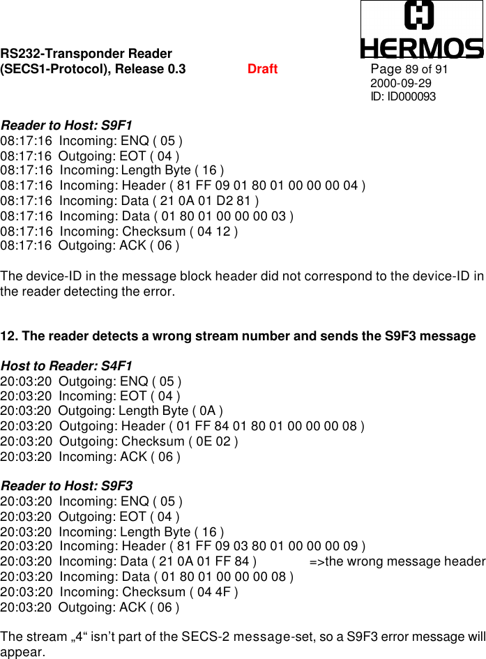
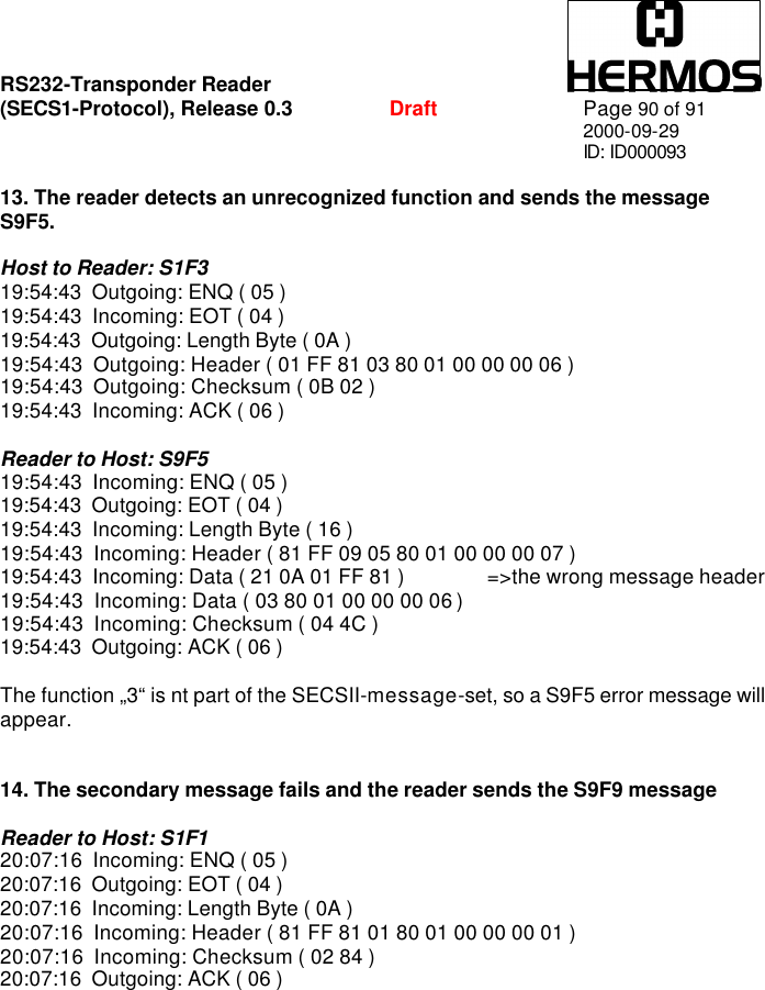
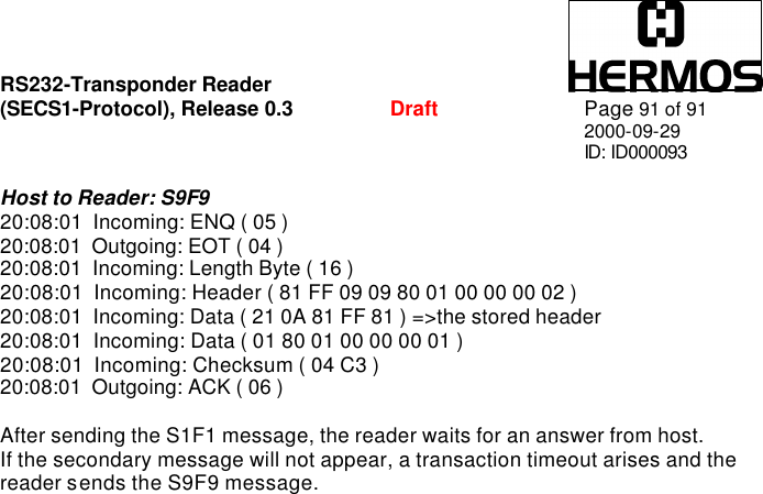
![RS232-Transponder Reader (SECS1-Protocol), Release 0.3 Draft Page 76 of 91 2000-09-29 ID: ID000093 9.5 System Errors 9.5.1 S9F1: UNRECOGNIZED DEVICE ID ( reader -> host ) The device-ID in the message block header did not correspond to the equipment device ID’s. S9F1 <B[10] MHEAD > . 9.5.2 S9F3: UNRECOGNIZED STREAM TYPE (reader -> host ) The reader does not recognize the stream type in the message block header. S9F3 <B[10] MHEAD > . 9.5.3 S9F5: UNRECOGNIZED FUNCTION TYPE (reader -> host ) The reader does not recognize the function number in the message block header. S9F5 <B[10] MHEAD > . 9.5.4 S9F7: ILLEGAL DATA (reader -> host ) The reader does not recognize the data in the message block header. S9F5 <B[10] MHEAD > . 9.5.5 S9F9: TRANSACTION TIMER TIME-OUT ( reader -> host ) This message indicates that a transaction timer has timed out and that the corresponding transaction has been aborted. Only the last sent message which has to be confirmed by the host is stored and controlled. S9F9 <B[10] SHEAD > .](https://usermanual.wiki/Brooks-Automation/TSG/User-Guide-298198-Page-76.png)