Brooks Automation TSG Inductive TAG System User Manual RS232 A5 E 0 3 SECS1
Brooks Automation (Germany) GmbH RFID Division Inductive TAG System RS232 A5 E 0 3 SECS1
Users Manual

Page 1 of 91
2000-09-29
Release: 0.3
ID: ID000093
*** Draft ***
RS232
-
Transponder Reader
(SEMI SECS-1-
Protocol)
Technical Reports

RS232-Transponder Reader
(SECS1-Protocol), Release 0.3 Draft Page 2 of 91
2000-09-29
ID: ID000093
1 SYSTEM DESCRIPTION.......................................................................................5
2 IMPORTANT NOTES:............................................................................................6
3 HARDWARE..............................................................................................................7
3.1 CONSTRUCTION..................................................................................................... 7
3.2 STANDARD-HOUSING........................................................................................... 9
3.3 HOUSING LID ....................................................................................................... 10
3.3.1 Without Membrane Keyboard ............................................................................. 10
3.3.2 With Membrane Keyboard ................................................................................. 12
3.4 TERMINAL CONNECTION.................................................................................... 15
3.5 ANTENNA.............................................................................................................. 18
3.5.1 Rod Antenna..................................................................................................... 18
3.5.2 Mini Antenna.................................................................................................... 18
3.5.3 Micro Antenna.................................................................................................. 19
3.5.4 Frame Antenna................................................................................................. 20
3.6 TECHNICAL DATA ANTENNA CABLE............................................................... 21
3.6.1 Cable of Rod Antenna and Frame Antenna.......................................................... 21
3.6.2 Cable of Mini Antenna and Micro Antenna .......................................................... 21
3.7 TECHNICAL DATA TRANSPONDER-READER.................................................... 21
3.8 POWER SUPPLY AND CURRENT INPUT ............................................................. 22
3.9 EXTERNAL OUTPUT (LED) ................................................................................ 22
3.10 ADDITIONAL INSTRUCTION FOR USE............................................................ 22
4 LICENSES AND CERTIFICATES ....................................................................23
5 WARRANTY AND LIABILITY.........................................................................24
6 READING AND WRITING RANGES ..............................................................25
6.1 READING RANGE ROD ANTENNA..................................................................... 25
6.2 WRITING RANGE ROD ANTENNA...................................................................... 26
6.3 READING RANGE MINI ANTENNA.................................................................... 27
6.4 WRITING RANGE MINI ANTENNA..................................................................... 28
6.5 READING RAGEN MICRO ANTENNA................................................................. 29
6.6 WRITING RANGE MICRO ANTENNA................................................................. 30
6.7 READING RANGE FRAME ANTENNA................................................................. 31
6.8 WRITING RANGE FRAME ANTENNA................................................................. 32
7 ACCESSORIES ........................................................................................................33
7.1 PLUGS / CABLING OF POWER............................................................................. 33

RS232-Transponder Reader
(SECS1-Protocol), Release 0.3 Draft Page 3 of 91
2000-09-29
ID: ID000093
7.2 PLUGS OF RS232-INTERFACE............................................................................ 33
7.3 PLUGS OF THE EXTERNAL SENSOR/ACTOR..................................................... 33
7.4 POWER SUPPLY.................................................................................................... 33
8 INTRODUCTION....................................................................................................34
8.1 SECS-1 IMPLEMENTATION................................................................................ 35
8.1.1 Character structure........................................................................................... 35
8.1.2 Block Transfer Protocol..................................................................................... 35
8.2 SECS-2 IMPLEMENTATION................................................................................ 40
8.2.1 Introduction...................................................................................................... 40
8.2.2 Data Items: ...................................................................................................... 42
8.2.3 Message set...................................................................................................... 43
8.2.4 Data Item Dictionary......................................................................................... 45
8.2.5 Data Item Dictionary:........................................................................................ 46
8.3 SEMI E99-0600.................................................................................................. 62
8.3.1 Introduction...................................................................................................... 62
8.3.2 State Models..................................................................................................... 63
9 MESSAGE DETAILS .............................................................................................66
9.1 EQUIPMENT STATUS............................................................................................ 66
9.1.1 S1F0: ABORT TRANSACTION (reader <-> host).............................................. 66
9.1.2 S1F1: ARE YOU THERE REQUEST ( reader <-> host, reply )............................ 66
9.1.3 S1F2: ON-LINE DATA ( host -> reader )........................................................... 66
9.1.4 S1F2: ON-LINE ( reader -> host ).................................................................... 66
9.1.5 S1F15: REQUEST OFF_LINE ( host ->reader, reply )........................................ 66
9.1.6 S1F16: OFFLINE ACKNOWLEDGE ( reader -> host )....................................... 67
9.1.7 S1F17: REQUEST ON_LINE ( host ->reader, reply ).......................................... 67
9.1.8 S1F18: ONLINE ACKNOWLEDGE ( reader -> host )......................................... 67
9.2 EQUIPMENT CONTROL........................................................................................ 68
9.2.1 S2F0: ABORT TRANSACTION (reader <-> host).............................................. 68
9.2.2 S2F13: EQUIPMENT CONSTANT REQUEST (host-> reader , reply).................. 68
9.2.3 S2F14: EQUIPMENT CONSTANT DATA (reader -> host )................................ 68
9.2.4 S2F15: NEW EQUIPMENT CONSTANT SEND ( host-> reader, reply ).............. 68
9.2.5 S2F16: NEW EQUIPMENT CONSTANT ACKNOWLEDGE (reader -> host )...... 69
9.2.6 S2F19: RESET SEND ( host -> reader, reply ).................................................... 69
9.2.7 S2F20: RESET ACKNOWLEDGE (reader -> host )............................................ 69
9.3 MATERIAL STATUS............................................................................................. 70
9.3.1 S3F0: ABORT TRANSACTION (reader <-> host).............................................. 70
9.3.2 S3F5: CASSETTE FOUND SEND ( reader -> host, reply ).................................. 70
9.3.3 S3F6: CASSETTE FOUND ACKNOWLEDGE ( host -> reader) ........................... 70
9.3.4 S3F7: CASSETTE LOST SEND ( reader -> host, reply )....................................... 71
9.3.5 S3F8: CASSETTE LOST ACKNOWLEDGE ( host -> reader )............................... 71
9.3.6 S3F11: READ MID AT I/O PORT (host ->reader , reply )................................... 71
9.3.7 S3F12: READ ACKNOWLEDGE ( reader -> host ) ........................................... 72
9.3.8 S3F13: RETURN READ MID ( reader -> host, reply ) ........................................ 72
9.3.9 S3F14: MID ACKNOWLEDGE ( host -> reader ).............................................. 72
9.3.10 S3F65: WRITE MID AT I/O PORT ( host -> reader, reply )................................. 72
9.3.11 S3F66: WRITE ACKNOWLEDGE ( reader -> host ).......................................... 73

RS232-Transponder Reader
(SECS1-Protocol), Release 0.3 Draft Page 4 of 91
2000-09-29
ID: ID000093
9.3.12 S3F67: RETURN WRITE SUCCESS ( reader -> host, reply ).............................. 73
9.3.13 S3F68: WRITE SUCCESS ACKNOWLEDGE ( host -> reader) ............................ 73
9.3.14 S3F73: LOCK MID AT I/O PORT ( host -> reader, reply ).................................. 73
9.3.15 S3F74: LOCK ACKNOWLEDGE ( reader -> host )........................................... 73
9.3.16 S3F75: RETURN LOCK SUCCESS ( reader -> host, reply )............................... 74
9.3.17 S3F76: LOCK SUCCESS ACKNOWLEDGE ( host -> reader)............................. 74
9.4 EXCEPTION HANDLING....................................................................................... 75
9.4.1 S5F0: ABORT TRANSACTION (reader <-> host).............................................. 75
9.4.2 S5F1: GATEWAY READER ALARM REPORT SEND (reader -> host, reply )....... 75
9.4.3 S5F2: ALARM REPORT ACKNOWLEDGE (host-> reader)................................ 75
9.5 SYSTEM ERRORS.................................................................................................. 76
9.5.1 S9F1: UNRECOGNIZED DEVICE ID ( reader -> host )..................................... 76
9.5.2 S9F3: UNRECOGNIZED STREAM TYPE (reader -> host )................................. 76
9.5.3 S9F5: UNRECOGNIZED FUNCTION TYPE (reader -> host ) ............................ 76
9.5.4 S9F7: ILLEGAL DATA (reader -> host ) ........................................................... 76
9.5.5 S9F9: TRANSACTION TIMER TIME-OUT ( reader -> host ) .............................. 76
9.6 SUBSYSTEM CONTROL AND DATA.................................................................... 77
9.6.1 S18F1: READ ATTRIBUTE REQUEST (RAR) (host -> reader, reply)................... 77
9.6.2 S18F2: READ ATTRIBUTE DATA (RAD) (reader -> host).................................. 77
9.6.3 S18F3: WRITE ATTRIBUTE REQUEST (WAR) (host -> reader, reply)................ 78
9.6.4 S18F4: WRITE ATTRIBUTE ACKNOWLEDGE (WAA) (reader -> host)............... 78
9.6.5 S18F5: READ REQUEST (RR) (host -> reader, reply)........................................ 79
9.6.6 S18F6: READ DATA (RD) (reader -> host)....................................................... 79
9.6.7 S18F7: WRITE DATA REQUEST (WAR) (host -> reader, reply).......................... 79
9.6.8 S18F8: WRITE DATA ACKNOWLEDGE (WDA) (reader -> host)........................ 80
9.6.9 S18F9: READ ID REQUEST (RIR) (host -> reader, reply) .................................. 80
9.6.10 S18F10: READ ID DATA (RID) (reader -> host)................................................ 80
9.6.11 S18F11: WRITE ID REQUEST (WIR) (host -> reader, reply) .............................. 81
9.6.12 S18F12: WRITE ID ACKNOWLEDGE (WIA) (reader -> host)............................. 81
9.6.13 S18F13: SUBSYSTEM COMMAND REQUEST (SCR) (host -> reader, reply)...... 81
9.6.14 S18F14: SUBSYSTEM COMMAND ACKNOWLEDGE (SCA) (reader -> host)..... 82
10 SECS-1 MESSAGE EXAMPLES........................................................................83

RS232-Transponder Reader
(SECS1-Protocol), Release 0.3 Draft Page 5 of 91
2000-09-29
ID: ID000093
1 System Description
The HERMOS Transponder Reader System is a high frequency identification
system using the FM-transmission.
The basic item is a transponder working as a forgery-proof electronic identity disc.
The reading unit of the system sends an energy impulse via the antenna. The
capacitor of the passive, battery-less transponder is charged by this impulse. After
that, the transponder returns a signal with the stored data.
The total reading cycle takes less than 100 ms.
As a sight-connection between transponder and reader is not absolutely necessary,
the transponder can also be identified through non-metallic material.
The data received by the transponder reader are transmitted via the serial interface.

RS232-Transponder Reader
(SECS1-Protocol), Release 0.3 Draft Page 6 of 91
2000-09-29
ID: ID000093
2 Important Notes:
This device complies with Part 15 of the FCC Rules. Operation is subject to the
following two conditions:
1) this device may not cause harmful interference , and
2) this device must accept any interference received, including interference that
may cause undesired operation.
CAUTION:
Changes or modifications not expressly approved by the party responsible for
compliance could void the user’s authority to operate the equipment.
NOTE:
This equipment has been tested and found to comply with the limits for a Class B
digital device, pursuant to part 15 of the FCC Rules. These limits are designed to
provide reasonable protection against harmful interference in a residential
installation.
This equipment generates, uses and can radiate radio frequency energy and, if not
installed and used in accordance with the instructions, may cause harmful
interference to radio communications. However, there is no guarantee that
interference will not occur in a particular installation. If this equipment does cause
harmful interference to radio or television reception, which can be determined by
turning the equipment off and on, the user is encouraged to try to correct the
interference by one or more of the following measures:
—Reorient or relocate the receiving antenna.
—Increase the separation between the equipment and receiver.
—Connect the equipment into an outlet on a circuit different from that to
which the receiver is connected.
—Consult the dealer or an experienced radio/TV technician for help.
RS232-Transponder Reader
(SECS1-Protocol), Release 0.3 Draft Page 7 of 91
2000-09-29
ID: ID000093
3 Hardware
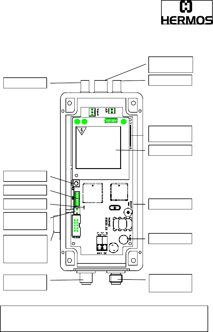
3.1 Construction
Attention:
ALL ANTENNA RESONANT CIRCUIT COMPONENTS CAN CARRY HIGH VOLTAGE
!
Fuse
Read LED
External output
HF
-
module
External input
connecto
r for
power
Plug for
antenna
Po
wer LED
RS232
interface
Reset button
RS232
interface
9 contacts Sub-
D female plug
Tuning
pushbutton
Prog. Port
Tuning LED’s

RS232-Transponder Reader
(SECS1-Protocol), Release 0.3 Draft Page 8 of 91
2000-09-29
ID: ID000093
The power LED signalizes whether 5V are existing on the board.
The HF-module is the analog part of the device. It triggers the antenna and
transmits the received data to the controller.
The 6 tuning LED’s show the switch status of the adjustment-relays (only valid if
automatic tuning integrated).
The data are passed down serially at the RS232 interface (9 contact Sub-D female
plug) with the different protocols. Baudrates of 300 Bd up to 115,2 kBd are possible.
Tuning-pushbutton, the reader start an automatic antenna tuning (only valid if
automatic tuning integrated).
The read-LED shortly flashes green, if the device tries to read respectively write.
The programming-port is scheduled for service purposes.
The external output, usually a LED, shows the switch status of the device
(depends on the software).
A sensor (for example an optical sensor) can be connected at the external input.
Fuse
TR5-housing, 500 mA T (low breaking)
RS232-Transponder Reader
(SECS1-Protocol), Release 0.3 Draft Page 9 of 91
2000-09-29
ID: ID000093
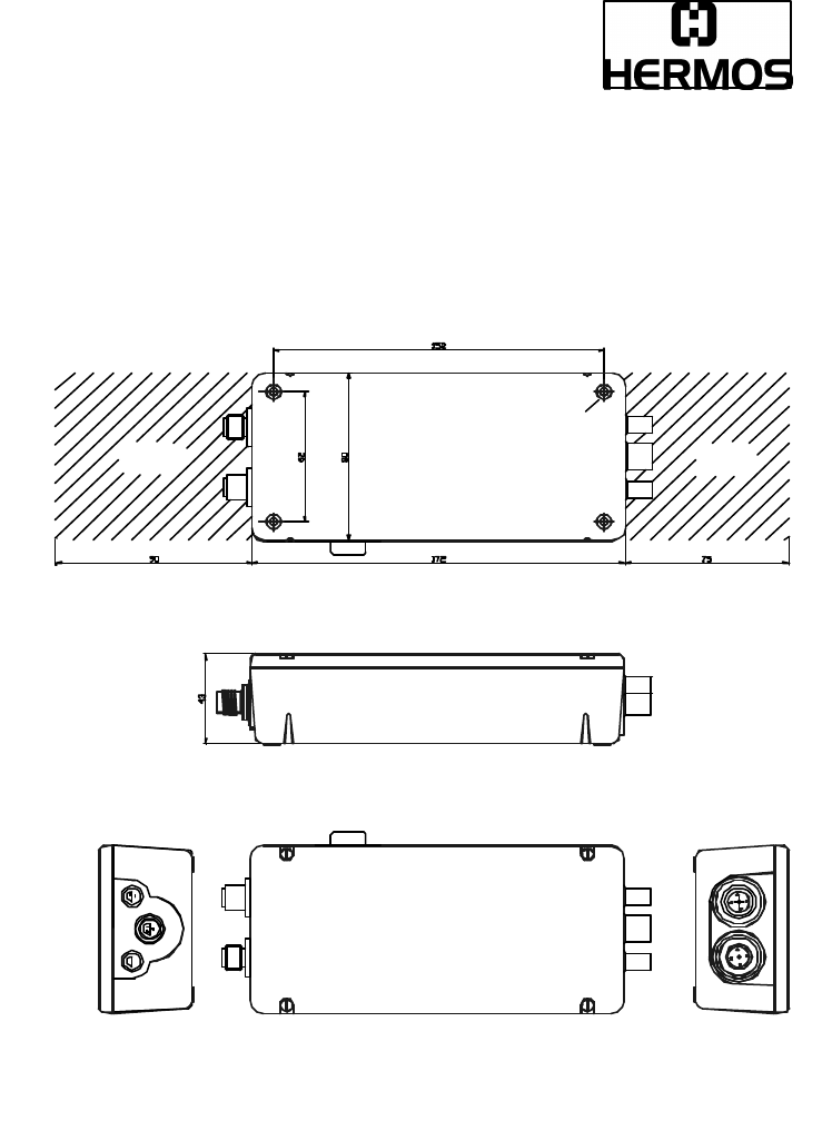
3.2 Standard-Housing
Fixing holes (4xØ4,2mm)
RS232-
Interface
Connector for
power
Connectors for
ext. input
antenna
ext. output
space for
plugs * space for
plugs *
* Keep space free for plugs. Dimensions
for straight cable plugs. Angled cable plugs
decrease space

RS232-Transponder Reader
(SECS1-Protocol), Release 0.3 Draft Page 10 of 91
2000-09-29
ID: ID000093
3.3 Housing Lid
3.3.1 Without Membrane Keyboard
Tuning
pushbutton
Power LED

RS232-Transponder Reader
(SECS1-Protocol), Release 0.3 Draft Page 11 of 91
2000-09-29
ID: ID000093
Power LED:
The LED lights after the device had been connected to the power supply.
Tuning pushbutton:
The automatic calibration is carried out after pushing the button which can be
reached by a drilled hole at the side of the housing (only valid if automatic tuning
integrated).
RS232-Transponder Reader
(SECS1-Protocol), Release 0.3 Draft Page 12 of 91
2000-09-29
ID: ID000093
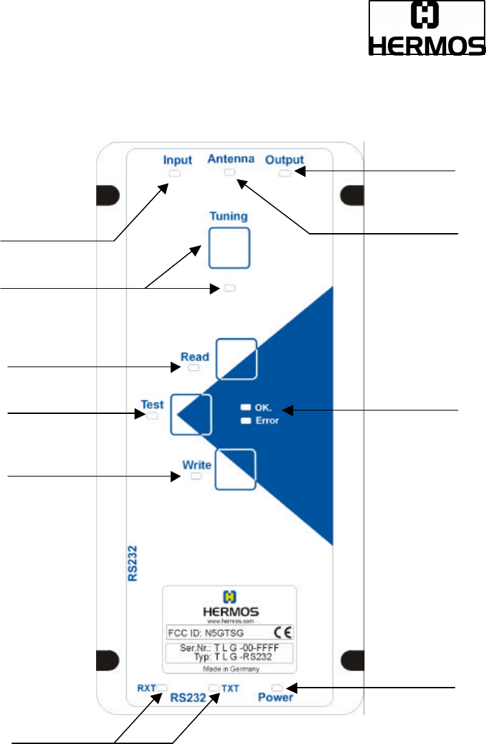
3.3.2 With Membrane Keyboard
RXT
-
/ TXT
-
LED
Write / LED
Test / LED
Read / LED
Tuning / LED
Input - LED
Power - LED
Status LED’s
Antenna - LED
Output - LED

RS232-Transponder Reader
(SECS1-Protocol), Release 0.3 Draft Page 13 of 91
2000-09-29
ID: ID000093
Power - LED:
If the device is connected to a power supply, the LED lights green and the reader is
ready for use.
Tuning / LED:
The antenna’s efficiency is optimized by pushing the automatic calibration key. The
LED lights up red during the calibration process and subsequently goes out when
the tuning had been successful. If a fault occurs, then the LED flashes as long as a
calibration initialized again had proceeded positively.
Possible faults could be a defect antenna or a strong metallic surrounding at the
antenna.
Antenna - LED:
If the antenna sends HF-signals (for example for loading a transponder or for
sending data), the LED is activated for this period.
Input - LED:
The input-LED signalizes a triggering of the external sensor respectively the
actuating of an external potential-free contact.
Output - LED:
If the external output is set, the LED lights; otherwise is does not light.
For a detailed description please see 3.9
RXT - und TXT - LED:
When data are transmitted via the RS232-interface the corresponding transmit- or
receive-LED lights.
TXT-LED (transmit) : Data are transmitted from the reader to the terminal. R ? T
RXT-LED (receive) : Data from the terminal are received in the reader. R ? T

RS232-Transponder Reader
(SECS1-Protocol), Release 0.3 Draft Page 14 of 91
2000-09-29
ID: ID000093
Test / LED:
The test mode serves for the checking of the most important reader features, the
reading respectively the writing, which are operated by pushing the corresponding
key in polling mode. If the device is in test mode, this is signalised by the test - LED.
The test-key has to be pushed again to leave the mode.
Read / - and Write / LED:
If the test mode is activated, then it is possible to bring the reader to permanent
reading respectively writing (polling) by pushing the read- respectively write-key.
This state is shown by a LED next to Read or Write.
By pushing the key which is not activated currently, the device changes its state
from Read to Write or vice versa. But if the activated key is pushed, the polling
mode is left, and the LED at Read respectively Write goes out.
If the reader is in one of these two states, the status-LED’s are showing whether the
process had been successful (green OK) or not (red ERROR).
RS232-Transponder Reader
(SECS1-Protocol), Release 0.3 Draft Page 15 of 91
2000-09-29
ID: ID000093
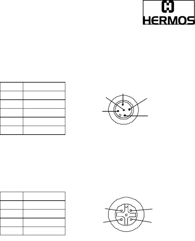
3.4 Terminal Connection
Built-in male plug, plastic (supply )
PIN Signal
1 +24V
2 0V
3 NC
4 NC
5 NC
Built-in female plug, metal (RS232-interface)
PIN Signal
1 NC
2 GND
3 RxD
4 TxD
1
2
3
4
5
3
4
1 2
RS232-Transponder Reader
(SECS1-Protocol), Release 0.3 Draft Page 16 of 91
2000-09-29
ID: ID000093
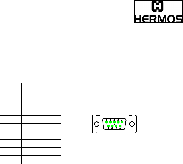
Sub-D female plug
The serial interface is also carried out with the Sub-D female plug (9 contacts), a
serial connection line (switched 1:1) can be used.
PIN DB9
1 NC
2 TXD
3 RxD
4 NC
5 GND
6 NC
7 NC
8 NC
9 NC
RS232-Transponder Reader
(SECS1-Protocol), Release 0.3 Draft Page 17 of 91
2000-09-29
ID: ID000093
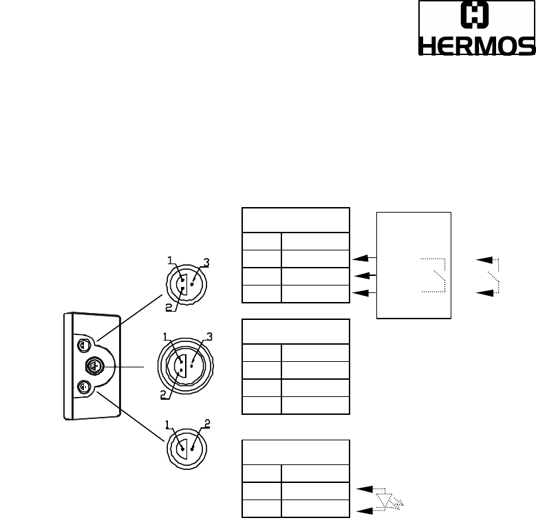
Ext. Output
Pin Signal
1
+5V
2
OUT LED
Ext. Input
Pin Signal
1
GND
2
+24V
3
IN npn
Antenna
Pin Signal
1
Antenna “+”
2
Antenna “-“
3
NC
GND
Output Q
+ 24V DC
positive
logic
The ext. output
is dimensioned
for connecting
a LED (without
resistor).
Sensor
Type:
NPN
floating
contact
RS232-Transponder Reader
(SECS1-Protocol), Release 0.3 Draft Page 18 of 91
2000-09-29
ID: ID000093
3.5 Antenna
3.5.1 Rod Antenna
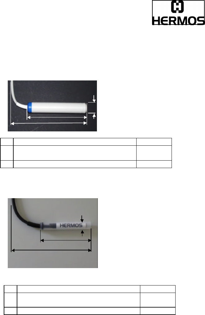
3.5.2 Mini Antenna
a2
a1 length of antenna cylinder 125mm
a2 complete mounting dimensions
(cable with 90° angle) 150mm
b1 diameter of antenna cylinder 23.0mm
b1
a1
a2
a1
b1
a1 length of antenna cylinder 68mm
a2 complete mounting dimensions
(cable with 90° angle) 85mm
b1 diameter of antenna cylinder 10.0mm
RS232-Transponder Reader
(SECS1-Protocol), Release 0.3 Draft Page 19 of 91
2000-09-29
ID: ID000093
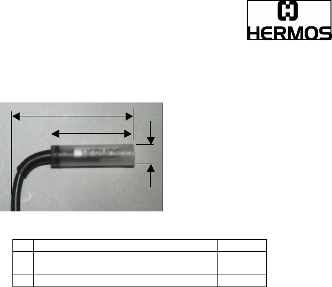
3.5.3 Micro Antenna
a2
a1
b1
a1 length of antenna cylinder 40mm
a2 complete mounting dimensions
(cable with 90° angle) 60mm
b1 diameter of antenna cylinder 10.0mm
RS232-Transponder Reader
(SECS1-Protocol), Release 0.3 Draft Page 20 of 91
2000-09-29
ID: ID000093
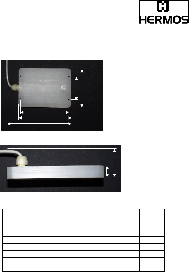
3.5.4 Frame Antenna
a1
a2
a3
b1
b2
c1
c2
a1 distance between the mounting holes (length) 148mm
a2 length frame antenna 161mm
a3 complete mounting dimensions length
(cable screwing at the side) 210mm
b1 distance between the mounting holes (width) 70mm
b2 width frame antenna 120mm
c1 high frame antenna 19mm
c2 complete mounting dimensions high
(cable screwing at the top) 70mm

RS232-Transponder Reader
(SECS1-Protocol), Release 0.3 Draft Page 21 of 91
2000-09-29
ID: ID000093
3.6 Technical Data Antenna Cable
3.6.1 Cable of Rod Antenna and Frame Antenna
diameter : 5,5mm
bending radius: 15 x diameter, only once 6 x diameter
material: PVC
3.6.2 Cable of Mini Antenna and Micro Antenna
diameter : 4,1mm
bending radius: 20 x diameter, only once 5 x diameter
material: PVC
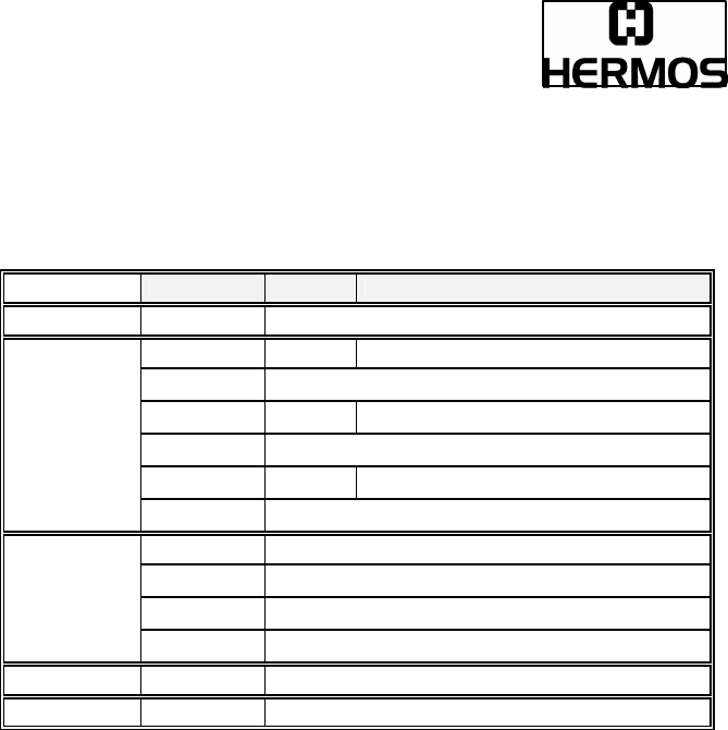
3.7 Technical Data Transponder-Reader
Parameter Value
Operation temperature 0 to +50°C
Stock temperature -25 to +70 °C
Permissible humidity @ 50C° 25 - 80 %
Transmitter frequency 134.2 kHz
Max. transmitting level in 3m distance 104 dBµV/m
Typ. period of charging impulse 50ms
Max. repeat of reading 4/s
Max. repeat of programming 1/s
Protection mode IP 40
Housing material ABS (UL94-V0)
Weight (with rod antenna and presence sensor) about 440g
Fuse type TR5 500mA (T)
Serial interface RS232 300 Bd – 115,2 kBd

RS232-Transponder Reader
(SECS1-Protocol), Release 0.3 Draft Page 22 of 91
2000-09-29
ID: ID000093
3.8 Power Supply and Current Input
Description
min Type max
unit
Voltage (proof against connecting to
the wrong terminal)
18 24 30 VDC
Current with/without presence sensor
(starting process excluded)
30 / 55 mA
Reading/writing impulse
rod antenna without/with presence
sensor
micro antenna without/with presence
sensor
160 / 185
140 / 165
mA
mA
3.9 External Output (LED)
Normally a LED is connected to the external output which is only relevant combined
with a read triggered by the external input.
The LED lights as long as a page is automatically read from a transponder.
If several pages are read in succession, the LED pulses because an
acknowledgement of the terminal has to follow each page.
If the terminal does not return any acknowledgement after a page of the automatic
read, the LED blinks as long as either a read process initialized again had been
completed successfully or a reset had been triggered.
If the reader cannot identify any transponder during the automatic read, the LED
lights permanently. This state can be reset by a reset or by a faultless automatic
reading cycle.
3.10 Additional Instruction for Use
Never expose the device to a intense change in temperature. Otherwise, water of
condensation can develop inside the device what can lead to damages.
Never bend or extend the antenna cable or expose it to other mechanical loads.

RS232-Transponder Reader
(SECS1-Protocol), Release 0.3 Draft Page 23 of 91
2000-09-29
ID: ID000093
4 Licenses and Certificates
• EC-Type Certification Registration Number: in preparation
• FCC ID: N5GTSG

RS232-Transponder Reader
(SECS1-Protocol), Release 0.3 Draft Page 24 of 91
2000-09-29
ID: ID000093
5 Warranty and Liability
The warranty period is 6 months and starts with the moment of the delivery of the
device which has to be proved by invoice or other documents.
The warranty includes the repair of all damages of the device, occurring within the
warranty period, which are evidently caused by faults of the material or productional
defects.
Not included into the warranty are damages caused by not prescribed connection,
inappropriate handling and non-observance of the technical reports.
RS232-Transponder Reader
(SECS1-Protocol), Release 0.3 Draft Page 25 of 91
2000-09-29
ID: ID000093
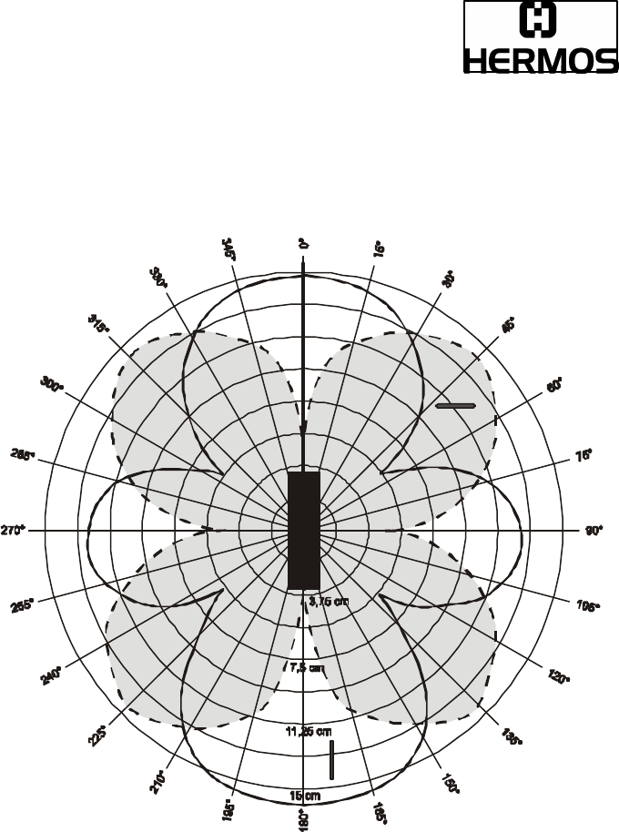
6 Reading and Writing Ranges
These diagrams have been taken at optimal conditions.
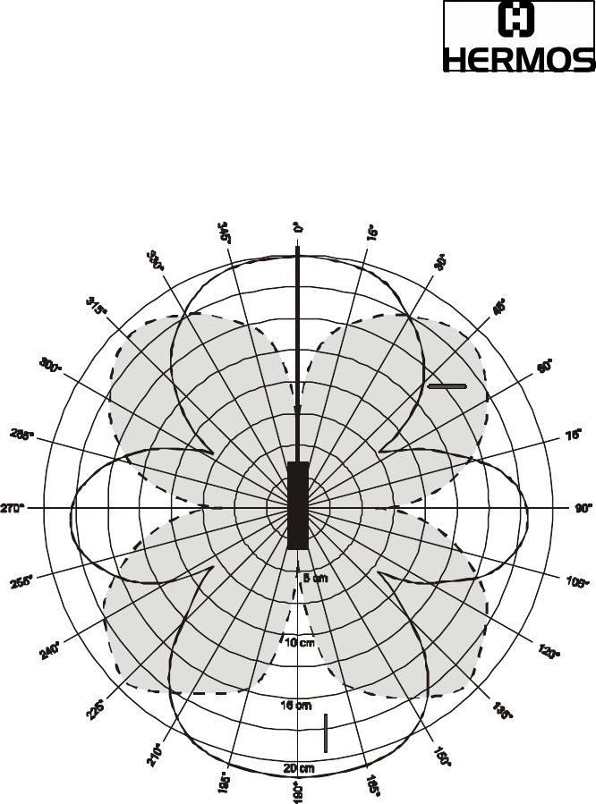
6.1 Reading Range Rod Antenna
Transponder: 32 mm multipage glass transponder
Antenna: HERMOS rod antenna (up to 1000mm lead)
________ Transponder parallel to antenna
- - - - - - - - Transponder 90° to antenna
RS232-Transponder Reader
(SECS1-Protocol), Release 0.3 Draft Page 26 of 91
2000-09-29
ID: ID000093
6.2 Writing Range Rod Antenna
Transponder: 32 mm multipage glass transponder
Antenna: HERMOS rod antenna (up to 1000mm lead)
________ Transponder parallel to antenna
- - - - - - - - Transponder 90° to antenna
RS232-Transponder Reader
(SECS1-Protocol), Release 0.3 Draft Page 27 of 91
2000-09-29
ID: ID000093
6.3 Reading Range Mini Antenna
Transponder: 32 mm multipage glass transponder
Antenna: HERMOS mini antenna (up to 1000mm lead)
________ Transponder parallel to antenna
- - - - - - - - Transponder 90° to antenna
RS232-Transponder Reader
(SECS1-Protocol), Release 0.3 Draft Page 28 of 91
2000-09-29
ID: ID000093
6.4 Writing Range Mini Antenna
Transponder: 32 mm multipage glass transponder
Antenna: HERMOS mini antenna (up to 1000mm lead)
________ Transponder parallel to antenna
- - - - - - - - Transponder 90° to antenna

RS232-Transponder Reader
(SECS1-Protocol), Release 0.3 Draft Page 29 of 91
2000-09-29
ID: ID000093
6.5 Reading Ragen Micro Antenna
Transponder: 32 mm multipage glass transponder
Antenna: HERMOS micro antenna (up to 1000mm lead)
________ Transponder parallel to antenna
- - - - - - - - Transponder 90° to antenna

RS232-Transponder Reader
(SECS1-Protocol), Release 0.3 Draft Page 30 of 91
2000-09-29
ID: ID000093
6.6 Writing Range Micro Antenna
Transponder: 32 mm multipage glass transponder
Antenna: HERMOS micro antenna (up to 1000mm lead)
________ Transponder parallel to antenna
- - - - - - - - Transponder 90° to antenna

RS232-Transponder Reader
(SECS1-Protocol), Release 0.3 Draft Page 31 of 91
2000-09-29
ID: ID000093
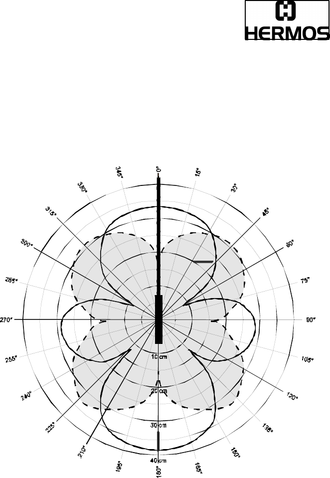
6.7 Reading Range Frame Antenna
Transponder: 32 mm multipage glass transponder
Antenna: HERMOS frame antenna (up to 1000mm lead)
________ Transponder parallel to antenna
- - - - - - - - Transponder 90° to antenna

RS232-Transponder Reader
(SECS1-Protocol), Release 0.3 Draft Page 32 of 91
2000-09-29
ID: ID000093
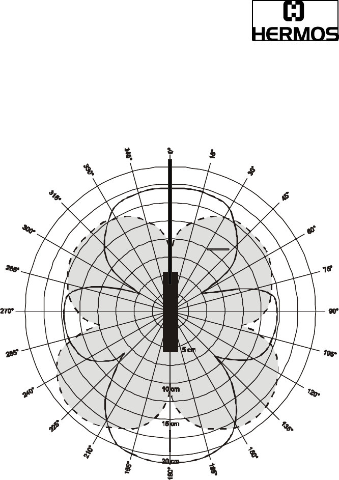
6.8 Writing Range Frame Antenna
Transponder: 32 mm multipage glass transponder
Antenna: HERMOS frame antenna (up to 1000mm lead)
________ Transponder parallel to antenna
- - - - - - - - Transponder 90° to antenna

RS232-Transponder Reader
(SECS1-Protocol), Release 0.3 Draft Page 33 of 91
2000-09-29
ID: ID000093
7 Accessories
7.1 Plugs / Cabling of Power
• Female plug, straight : KBV-GK
• Female plug, angled : KBV-WK
• Current connector with two cores : KBV24
7.2 Plugs of RS232-Interface
• Shielded male plug, straight : KSRS-GM
7.3 Plugs of the External Sensor/Actor
• Cable plug, ext. sensor, metal : KS-SENS1
• Cable plug, ext. output, metal : KS-LED1
• External optical coupler for top-hat rail installation
(can be connected directly on the LED,
output data: 48V DC 100mA ) : LDOP
7.4 Power Supply
• Power supply, input: AC 120-230 V,
output: DC 18V / 0,3 A: SVG0,3

RS232-Transponder Reader
(SECS1-Protocol), Release 0.3 Draft Page 34 of 91
2000-09-29
ID: ID000093
8 Introduction
The SECS-1 standard defines a communication interface suitable for the exchange
of messages between semiconductor processing equipment and a host. A host is a
computer or network of computers which exchanges information with the
equipment to accomplish manufacturing.
The standard does not define the data contained within a message. The meaning
of messages must be determined through some message contents standard such
as SEMI Equipment Communications Standard E5 (SECS-2).
This standard provides the means for independent manufacturers to produce
equipment and hosts which can be connected without requiring specific knowledge
of each other.
The SECS-1 protocol can be thought of as a layered protocol used for point to point
communication. The levels within SECS-1 are the physical link, block transfer
protocol and message protocol.
It is not intent of the standard to meet the communication needs of all possible
applications. For example, the speed of RS232 may be insufficient to meet the
needs of transferring mass amounts of data or programs in a short period of time,
such as might be required by high speed functional test applications.
In a network, the roles of host and equipment might be assumed by any party in the
network. In this situation, one end of the communications link must assume the role
of the equipment and the other the role of the host.
Electronic Industries Association Standards:
E|A RS-232-C Interface between Data Terminal Equipment and Data
Communication Equipment Employing Serial Binary Data
Interchange.

RS232-Transponder Reader
(SECS1-Protocol), Release 0.3 Draft Page 35 of 91
2000-09-29
ID: ID000093
8.1 SECS-1 Implementation
This message set describes the communication between a SECS-1 reader and a
host. The communication between the host and the transponder-reader happens
via a RS232 interface (SECS-1).
8.1.1 Character structure
Data will be transmitted or received in a serial bit stream of 10 bits per character at
one of the specified data rates. The standard character has one start bit(0),
8 data bits and one stop bit(1). All bit transmissions are of the same duration.
SECS1 performs no parity or other verification of the individual bytes.
8.1.2 Block Transfer Protocol
The gateway will use an interpretation of SECS-1 by a serial transport layer. The
following are some points to note about this implementation.
1. Master-Slave
The host connects to the reader. When there is contention the host "gives in" (i.e.
receives before sending).
In the communication course the reader takes on the part of the master and the
host the part of the slave!
2. Control Characters
The four standard handshake codes used in the block transfer protocol are shown
in the table.
<ENQ> 0x05 Request to Send
<EOT> 0x04 Ready to Receive
<ACK> 0x06 Correct Reception
<NAK> 0x15 Incorrect Reception
RS232-Transponder Reader
(SECS1-Protocol), Release 0.3 Draft Page 36 of 91
2000-09-29
ID: ID000093
3. Message Block Structure
SECS message blocks have the form:
Byte msb Description
Length 0 Length without checksum , 10 – 254
1 R Upper Device ID (Reader ID)
2 Lower Device ID (Gateway ID)
3 W Upper Message ID (Stream)
4 Lower Message ID (Function)
5 E Upper Blocknumber
Header
6 Lower Blocknumber
7 System Byte 1
8 System Byte 2
9 System Byte 3
System
Bytes
10 System Byte 4
Text 11 – 254 message text , user data
Checksum 255 , 256 16 Bit unsigned checksum
The operation of all communication functions above the block transfer protocol is
linked in information contained in a 10-byte data element called the header.
The header is always the first 10 bytes of every block sent by the block transfer
protocol.
The length includes all the bytes sent after the length byte, excluding the two
checksum bytes. The maximum block length allowed by SECS-1 is 254 bytes and
the minimum is 10 bytes.
The reverse bit (R-bit) signifies the direction of a message. The R-bit (msb) is set
to 0 for messages to the equipment and set to 1 for messages to the host.
The device-ID is a definite number to contact the reader.
The device-ID consists of the 8 bit gateway-ID (bit0-bit7), which is identical with the
last two characters of the readers serial number and a 5 bit fixed reader number
(bit8-bit12 = 0x01).
Bit13 to Bit14 are reserved for future extensions!

RS232-Transponder Reader
(SECS1-Protocol), Release 0.3 Draft Page 37 of 91
2000-09-29
ID: ID000093
Upper Device-ID
Lower Device-ID
Direction reader to host: 0x81xx *
Direction Host to equipment (HERMOS SECS-1 Reader): 0x01xx *
* … the serial number is on a sticker on the cap of each reader
The W-Bit is used to indicate that the sender of a primary message expects a reply.
A value of one in the W-bit means that a reply is expected.
The message ID identifies the format and contents of the message being sent.
A primary message is defined as any odd numbered message.
A secondary message is defined as even any numbered message.
The end bit is used to determine if a block is the last block of message. A value of
one means that the block is the last block.
A message sent as more than one block is called a multi-block message. A block
number of one is given to the first block, and the block number is incremented by
one for each subsequent block until the entire message is sent.
As all messages can ever be sent in one block, the block number always has the
value 1.
The system bytes in the header of each message for a given device ID must
satisfy the following requirements:
• The system bytes of a primary message has to be distinct from those of
all currently open transactions initiated from the same end of the
communications link.
• The system bytes of the reply message are required to be the same as
the system bytes of the corresponding primary message.
The system bytes are incremented for each primary message. Only the two lowest
bytes (byte 9 and 10 of the header) are incremented. For a primary message of the
reader, additionally byte 8 of the header is used for the reader action number.
The checksum is calculated as the numeric sum of the unsigned binary values of
all the bytes after the length byte and before the checksum in a single block.
R
Not used
0x01
serial number of the reader
RS232-Transponder Reader
(SECS1-Protocol), Release 0.3 Draft Page 38 of 91
2000-09-29
ID: ID000093
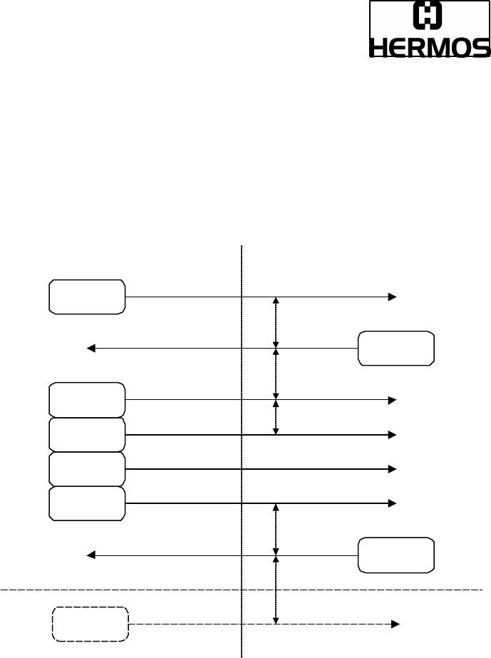
4. Block Transfer Protocol
The drawing below illustrates some simple message interactions between the host
and the equipment. The figure shows the handshake sequence possible to acquire
the status of the equipment.
When the host wants to send, it first sends an <ENQ> and then tries to read.
If it receives an <EOT> , it sends its message and then expects an <ACK>.
If it receives an <ENQ>, it puts off sending its message, sends an <EOT> and then
reads the other message.
Sending and receiving via the SECS-1 interface alternate with each other!
ENQ
EOT
Länge
Header
Checksum
Daten
ACK
ENQ
Sender: Empfänger:
T2
T2
T1
T2
T4 (bei mehreren Blöcken)
(HOST / READER) (READER / HOST)

RS232-Transponder Reader
(SECS1-Protocol), Release 0.3 Draft Page 39 of 91
2000-09-29
ID: ID000093
When both the host and the equipment try to send at the same time, the host must
cancel its inquiry because the host works in slave mode. First he has to receive the
equipment message because the reader is the master. Only now the host is allowed
to send his message.
For more detailed information about all possible cases see SEMI E4-0997.
(SEMI Equipment Communication Standard 1 Message Transfer SECS-1)

RS232-Transponder Reader
(SECS1-Protocol), Release 0.3 Draft Page 40 of 91
2000-09-29
ID: ID000093
8.2 SECS-2 Implementation
8.2.1 Introduction
The SEMI Equipment Communication Standard Part 2 (SECS-2) defines
the details of the interpretation of messages exchanged between intelligent
equipment and a host.
It is the intent of this standard to be fully compatible with SEMI Equipment
Communication Standard E4 (SECS-1).
The messages defined in this specification support the typical activities
required for the HERMOS SECS-1 transponder reader.
SECS-2 gives form and meaning to messages exchanged between
equipment and host using a message transfer protocol, such as SECS-1.
SECS-2 defines the method of conveying information between equipment
and host in the form of messages.
These messages are organized into categories of activities, called streams,
which contain specific messages, called functions. In SECS-2, messages
are identified by a stream code (0-127, 7bits) and a function code (0-255,
8 bits). Each combination of stream and function represents a distinct
message identification.
SECS-2 defines the structure of messages into entities called items and list
of items. These data structures define the logical divisions of the message,
as distinct from the physical division of the message transfer protocol.
An item is an information packet which has a length and format defined by
the first 2,3, or 4 bytes of the item. These bytes are called the item header.
The item header consists of the format byte and the length byte as shown.

RS232-Transponder Reader
(SECS1-Protocol), Release 0.3 Draft Page 41 of 91
2000-09-29
ID: ID000093
A list is an ordered set of elements, where an element can be either an item or a
list. The list header has the same form as an item header with format type 0.
However, the length byte refers to the number of elements in the list rather than to
the number of bytes.
Byte Name Description
0 Format and
number of the
length-bytes
The data format is coded in the upper 6 bits.
The two less significant bits determine the
number of the following length-bytes.
1
1-2
1-3
Length-bytes
The length corresponds to the number of the
bytes of a data element. In the “List“ format the
length corresponds to the number of the list
elements.
The standard does not require the minimum
possible number of length-
bytes for a given data
length
Next
<Length> Data
Data bytes of a data element or number of the
data elements in case of the „List“ format.

RS232-Transponder Reader
(SECS1-Protocol), Release 0.3 Draft Page 42 of 91
2000-09-29
ID: ID000093
8.2.2 Data Items:
The formats represent arrays of types: <type>[number of elements] where <type> is
one of the following:
Data items examples:
Oct-Code
Hex-Code
Format Meaning Example
00 01 List List element with the
number of the „Length“
data elements
<L2>
<A “H
ello“>
<B 0x00>
11 25 Boolean
1 – Byte Boolean
false = 00 ; true != 00
<I1 123>
10 21 Binary Byte sequence of the
length „Length“
<I1 123>
20 41 Ascii Printable Ascii signs
31 65 I1 1 - Byte signed Integer
<I1 123>
32 69 I2 2 - Byte signed Integer
<I2
–12345>
34 71 I4 4 - Byte signed Integer
<I4 2147483647>
30 61 I8 8 - Byte signed Integer
<I8
–931372980293834>
51 A5 U1 1 - Byte unsigned Integer
<U1 0>
52 A9 U2 2 - Byte unsigned Integer
<U2 #empty>
54 B1 U4 4 - Byte unsigned Integer
<U4 429489725>
50 A1 U8 8 - Byte unsigned Integer
<U8 763468676756767>
40 91 F8 8 - Byte floating point
<F8 1.223 e204>
44 81 F4 4 - Byte floating point
<F4
-1.23 >
Meaning Format
Length
1- Byte Integer 65 01 xx
4- Byte Integer 71 04 MSB ... ... LSB
ASCII 41 06 1.chr
2.chr
3.chr
4.chr
5.chr
6.chr
zero-length xx 00
List Data Item 01 03 1. element 2. element 3. element

RS232-Transponder Reader
(SECS1-Protocol), Release 0.3 Draft Page 43 of 91
2000-09-29
ID: ID000093
8.2.3 Message set
The SECSII-message-set used by the HERMOS SECS-1 reader consist of 6
different stream types.
Stream 1 : (Equipment status)
- S1F1 and S1F2 Are you there request
- S1F15 and S1F16 Request offline
- S1F17 and S1F18 Request online
Stream 2 : (Equipment control)
- S2F13 and S2F14 equipment constant request
- S2F15 and S2F16 new equipment constant request
- S2F19 and S2F20 reset send
Stream 3 : (Material status)
- S3F5 and S3F6 cassette found send
- S3F7 and S3F8 cassette lost send
- S3F11 and S3F12 read MID at I/O port
- S3F13 and S3F14 return read MID
- S3F65 and S3F66 write MID at I/O port
- S3F67 and S3F68 return write success
Stream 5 : (Exception handling)
- S5F1 and S5F2 alarm report send
Stream 9 : (System errors)
- S9F1 unrecognized device ID
- S9F3 unrecognized stream type
- S9F5 unrecognized function type
- S9F7 illegal data
- S9F9 transaction timer timeout
In attention of the SEMI E99 Carrier ID Read/Writer functional standard for SECS-1
and SECS-2 protocol, the HERMOS SECS-1 reader supports the defined Stream
18 messages.

RS232-Transponder Reader
(SECS1-Protocol), Release 0.3 Draft Page 44 of 91
2000-09-29
ID: ID000093
Stream 18 : (Equipment status)
- S18F1 and S18F2 read attribute request /data
- S18F3 and S18F4 write attribute request/acknowledge
- S18F5 and S18F6 read request/data
- S18F7 and S18F8 write request/acknowledge
- S18F9 and S18F10 read ID request/data
- S18F11 and S18F12 write ID request/acknowledge
- S18F13 and S18F14 subsystem command
request/acknowledge

RS232-Transponder Reader
(SECS1-Protocol), Release 0.3 Draft Page 45 of 91
2000-09-29
ID: ID000093
8.2.4 Data Item Dictionary
This section defines the data items used in the standard SECS-2 messages
described in the section “Message Details”.
Syntax:
Name: A unique name for this data item. This name is used in the message
definitions.
Format: The allowable item format code which can be used for this standard
data item. Item format codes are shown in hex and octal, as
described inchapter 1.2.2 data items. The notification “3()” indicates
any of the signed integer formats (30,31,32,34).
Description: A description of the data item, with the meanings of specific
values.
Where used: The standard messages in which this data items appears.
RS232-Transponder Reader
(SECS1-Protocol), Release 0.3 Draft Page 46 of 91
2000-09-29
ID: ID000093
8.2.5 Data Item Dictionary:
ACKC3 Format: B[1]
Acknowledge Code
0 : Sensor 0 was the initiator
1 : Sensor 1 was the initiator
>1 : error, not accepted
Where used: S3F6, S3F8
ACKC5 Format: B[1]
Acknowledge Code
0 : no error
>0 : error, not accepted
Where used: S5F2
ALCD Format: B[1]
Alarm Code Byte.
Only the occurring of a failure is told. Failures will not be reset on principle.
Bit 8 = 1 : alarm is set
Where used: S5F1

RS232-Transponder Reader
(SECS1-Protocol), Release 0.3 Draft Page 47 of 91
2000-09-29
ID: ID000093
ALID Format: U1[1]
Alarm Identifier
0: none error
1: auto read failed, the reader is engaged in doing something
2: reserved
3: reserved
4: no tag could be recognized when the sensor was covered or carrier had
been removed prematurely (sensor uncovered!)
5: invalid command or parameter detected
6: unknown error
7: reserved
8: parity- or checksum error detected
9: unexpected confirmation was sent
10: locked page could not write
11: reserved
12: bad type of transponder
13: external read or write failed because the sensor is not covered
(no carrier detected)
14: reserved
15: reserved
Where used: S5F1
ALTX Format: A[max40]
Alarm Text
The length of the alarm text is 0 to 40 signs.
According to the reader version, state information of the sensor respectively of the
sensors are also transmitted during a failure message of the reader.
The information has to be interpreted as follows:
ALTX[0] Initiator of a failure message
“0”: Sensor 0
“1”: Sensor 1
“F”: cannot be assigned

RS232-Transponder Reader
(SECS1-Protocol), Release 0.3 Draft Page 48 of 91
2000-09-29
ID: ID000093
ALTX[1] State of sensor 0
“0”: Sensor not occupied
“1”: Sensor is occupied
“E”: Sensorstate is not available
“F”: Sensor not defined
ALTX[2] State of sensor 1
“0”: Sensor not occupied
“1”: Sensor is occupied
“E”: Sensorstate is not available
“F”: Sensor not defined
ALTX[3] ‘:’ a colon separates the alarm text from the sensor states
Where used: S5F1
ATTRID Format: A[max25]
Description: Identifies for an attribute for a specific
type of object.
CIDRW Attributes definitions:
“Configuration”… Number of heads
“AlarmStatus” Current CIDRW substate of ALARM STATUS
“OperationalStatus” Current CIDRW substate of OPERATIONAL
“SoftwareRevisionLevel” Revision (version) of Software 8 byte maximum
Head Attribute Definitions:
“HeadStatus” The current state
“HeadID” Head number 0-31 (2 digits)
Where used: S18F1, S18F3

RS232-Transponder Reader
(SECS1-Protocol), Release 0.3 Draft Page 49 of 91
2000-09-29
ID: ID000093
ATTRVAL Format: A[max4]
Description: Value of the specified attribute.
CIDRW Attributes definitions:
“Configuration” Number of heads
“01”
“AlarmStatus” Current CIDRW substate of ALARM STATUS
“0” … NO
“1” … ALARMS
“OperationalStatus” Current CIDRW substate of OPERATIONAL
“IDLE” … reader in IDLE mode
“BUSY” … reader is busy
“MANT” … maintenance mode
“SoftwareRevisionLevel” Revision (version) of Software 8 byte
maximum
Head Attribute Definitions:
“HeadStatus” The current state
“IDLE” … reader in IDLE mode
“BUSY” … reader is busy
“NOOP” … not operating
“HeadID” Head number 0-31 (2 digits)
“00” … Reader 0
“31” … Reader 31
Where used: S18F1, S18F3
CPVAL Format: A[max2]
Description: State request value.
“OP” … operating state
“MT” … maintenance state
Where used: S18F13
RS232-Transponder Reader
(SECS1-Protocol), Release 0.3 Draft Page 50 of 91
2000-09-29
ID: ID000093
DATA Format: A[max8]
Description: A vector or string of unformatted data.
The first page (page 1) of each transponder contains the MID.
Be careful: A modification of this page would also cause a
modification of the MID!
Multipage-transponder: DATA area page 2 – page 17
Read/Write-Transponder: DATA correspond to MID
Read/Only-Transponder : DATA correspond to MID
Where used: S18F6, S18F7
DATALENGTH Format: UI2
Description: Total bytes to be sent.
The DATALENGTH corresponds to the quantity of bytes a
transponder page consists of.
Valid range is from 0x0001 up to 0x0008 Bytes.
Where used: S18F5, S18F7
DATASEG Format: A[2]
Description: Used to identify the data requested.
The DATASEG corresponds to the page number (PAGEID) of
multipage-, read/only- and read/write-transponders
Multipage-transponder (page 1 up to page 17) :
In case of reading only one page of the multipage-transponder, please note the
following:
“01” : page 1 “81” : locked page 1
... ...
“11” : page 17 “91” : locked page 17
Read/Only-Transponder : “F0” : read only the one page
Read/Write-Transponder: “F1” : read or write only the one page
Where used: S18F5, S18F7
RS232-Transponder Reader
(SECS1-Protocol), Release 0.3 Draft Page 51 of 91
2000-09-29
ID: ID000093
EAC Format: B[1]
Acknowledge code for new reader constant
0: parameter set successfully
1: parameter could not be set
Where used: S2F16
ECID Format U1[1]
Parameter number of reader (look data item ECV)
Where used: S2F13, S2F15
ECV Format U1[1]
Reader parameters definition. The values here are shown as decimal-values!
Parameters:
Parameter 0: Gateway-ID
The gateway-ID is a part of the device-ID. The HERMOS SECS-1 reader works
simultaneously as gateway and reader.
In the header of a message it is the “lower message ID”.
00 .. 255
default: last two characters of serial number.

RS232-Transponder Reader
(SECS1-Protocol), Release 0.3 Draft Page 52 of 91
2000-09-29
ID: ID000093
Parameter 1: Baudrate
Data transmission rate to the SECS-Host
3 : 300 Baud
6: 600 Baud
12: 1200 Baud
24: 2400 Baud
48: 4800 Baud
96: 9600 Baud
192: 19200 Baud
200: 38400 Baud
201: 57600 Baud
202: 115200 Baud
default: (200) 38400 Baud (look covering letter of the reader)
Parameter 2: Inter-Character-Timeout T1
1 .. 100 1/10s
default: (5) 0.5s
Parameter 3 : Block-Protocol-Timeout T2
2 .. 250 1/10s
default: (100) 10s
Parameter 4: Reply-Timeout T3
1 .. 120 1s
default: 45s
Parameter 5: Inter-Block Timeout T4
This parameter is without effect at the moment when no used message is larger
than a block.
1 .. 120 1s
default: 45s
Parameter 6: Retry-Limit RTY
Number how often a question or a message shall be repeated.
0 .. 31
default: 3
Parameter 7-19: not defined !
Parameter 20: sensordelay for sensor 0
Delay for auto read if using a sensor:
0 .. 255 1/10 s
default: (10) 1s

RS232-Transponder Reader
(SECS1-Protocol), Release 0.3 Draft Page 53 of 91
2000-09-29
ID: ID000093
Parameter 21: not defined!
Parameter 22: sensor triggered action for sensor 0 and sensor 1
0 : read all transponders
1 : read the page 1 of a multipage-transponder
...
17 : read the page 17 of a multipage-transponder
240 : read a read/only-transponder
241 : read a read/write-transponder
default: : (0) read all transponders
Parameter 23: triggered read-frequency
Time between two attempts to read or write a transponder;
the read-frequency if there is a triggered read (no polling).
15 .. 100 % from 1s
default: (50%) 500ms
Parameter 24: r/w maxrepeat
Maximum number of repeat attempts to read or write a transponder
0 .. 255
default: 20
Parameter 25: not defined !
Parameter 26: sensor activity
The transponder reader offers the possibility to deactivate the connected sensor.
Parameter 26 realizes this with the following values:
0 No sensor defined
1 Only sensor 0 defined
default: 1
Parameter 27: watchport for sensor 0
Enables a message to the host, if a cassette is detected on I/O port or is removed
from I/O port.
A sensor is needed to use this message! :
0 report nothing
1 report cassette is removed
2 report cassette is detected
3 report cassette is detected and cassette is removed
default: (1) report cassette is removed

RS232-Transponder Reader
(SECS1-Protocol), Release 0.3 Draft Page 54 of 91
2000-09-29
ID: ID000093
Parameter 28: transmitter-level
The intensity of field strength to load a transponder.
The default value (1) should not change!
0 reduced field strength
1 maximum field strength
default: (1) maximum field strength
Parameter 29: transponder load duration
The used time to load a transponder.
The default value (50ms) should not change!
00 .. 255 ms
default: (50) 50ms
Parameter 30: not defined !
Parameter 31: not defined !
Parameter 32: not defined !
Parameter 33: automatic environment adjustment
The influence of interferences in the environment of the readers can be minimized
by an automatic adjustment during the operation. If the automatic adjustment is
deactivated, an adjustment to the environment will only be effected in case of a
reset.
0: deactivated automatic environment adjustment
1: activated automatic environment adjustment
default: (0) deactivated
Parameter 34: sensortype for sensor 0
Type of sensor signal to start the auto read if using one sensor:
0: auto read starts if sensor 0 is covered
1: auto read starts if sensor 0 is interrupted
default: (0) sensor 0 is covered
Where used: S2F13, S2F15
MDLN Format: A[6]
Equipment Model Number.
Where used: S1F2

RS232-Transponder Reader
(SECS1-Protocol), Release 0.3 Draft Page 55 of 91
2000-09-29
ID: ID000093
MF Format: B[1]
Material format code.
20: The material port number corresponds to the sensor number and state
Where used: S3F5, S3F7
MHEAD Format: B[10]
SECS Message Block Header associated with message block in error.
Where used: S9F1, S9F3, S9F5, S9F7, S9F9
MID Format: A[max16]
Description: Material ID.
The MID corresponds to the first page (16 characters from
‘0’…’F’) of the TIRIS transponder. Depend on the transponder-
type, it is possible to modify the MID.
Multipage-transponder: MID is stored in page 1 (writeable)
Read/Write-Transponder: MID correspond to DATA (writeable)
Read/Only-Transponder : MID correspond to DATA (fix)
Where used: S18F10, S18F11

RS232-Transponder Reader
(SECS1-Protocol), Release 0.3 Draft Page 56 of 91
2000-09-29
ID: ID000093
MIDAC Format: B[1]
Acknowledge Code
0 : material-ID acknowledged; the sensor 0 was the initiator
1 : not defined
2 : material-ID acknowledged - reaction on externally triggered action;
the message cannot be related to any sensor
>2 : material-ID not acknowledged
The initiator can be determined from the data item Portnumber PTN.
Where used: S3F14, S3F68
MIDRA Format: B[1]
Material ID acknowledge code
2: acknowledge, will send MID later in S3F13 or S3F67
Where used: S3F12
OBJSPEC Format: A[x]
Description: A text string that has an internal format and that is used to point to
a specific object instance. The string is formed out of a sequence
of formatted substrings, each specifying an object’s type and
identifier. The substring format has the following four fields.
Object type, colon character ”:” object identifier, greater-than symbol “>”
Where the colon character “:” is used to terminate an object type
and the greater than symbol “>” is used to terminate an identifier
field. The object type field may be omitted where it may be
otherwise determined. The final “>” is optional.

RS232-Transponder Reader
(SECS1-Protocol), Release 0.3 Draft Page 57 of 91
2000-09-29
ID: ID000093
OFLACK Format: B[1]
Acknowledge code for offline request.
0: gateway is offline
Where used: S1F16
ONLACK Format: B[1]
Acknowledge code for online request.
0: gateway is online
Where used: S1F18
PAGE_ID Format: B[1]
Page number of multipage-, read/only- and read/write-transponders
Multipage-transponder (page 1 up to page 17) :
In case of reading only one page of the multipage-transponder, please note the
following:
0x01 : (1) page 1 0x81 : (129) locked page 1
... ...
0x11 : (17) page 17 0x91 : (146) locked page 17
Read/Only-Transponder :
0xF0 : (240) read only the one page
Read/Write-Transponder:
0xF1 : (241) read or write only the one page
Where used: S3F11
RS232-Transponder Reader
(SECS1-Protocol), Release 0.3 Draft Page 58 of 91
2000-09-29
ID: ID000093
PAGEDATA Format: B[9]
The cassette identifier that has been read or shall be written. The PAGEDATA
corresponds to the value of a transponder page.
PAGEDATA [0] corresponds to the page number. The values of the
page number (MID[0]) are shown in the data item “PAGE_ID”.
PAGEDATA [1] – the 8 byte (one page) of the transponder-ID are following.
PAGEDATA [8]
Where used: S3F7, S3F12, S3F13, S3F65
PTN Format: B[1]
Information about the state of up to 2 sensors and the initiator of the message.
For special applications, the reading process of the transponder reader is triggered
by 2 sensors. In this case it is necessary to be able to distinguish between the 2
sensors. The initiator represents the number of the sensor which has caused the
generation of a message.
Default: only sensor 0 is defined!
bit 7 ........ bit 0
Initiator Sensor 1 Sensor 0
Sensor 0: bit0 – bit2
The actual state of sensor 0 is described in three bits
0 Sensor not occupied
1 Sensor occupied
7 Sensor not defined
Sensor 1: bit3 – bit5 (defined for future developments)
The actual state of sensor 1 is described in three bits
0 Sensor not occupied
1 Sensor occupied
7 Sensor not defined

RS232-Transponder Reader
(SECS1-Protocol), Release 0.3 Draft Page 59 of 91
2000-09-29
ID: ID000093
Initiator: bit6 – bit7
The initiator represents the number of the sensor which has caused the generation
of a message
0 Sensor 0
1 Sensor 1 (not realized at present)
3 cannot be assigned
Where used: S3F5, S3F7, S3F12, S3F13, S3F67
RAC Format: B[1]
Reset acknowledge code.
0: reset to be done
1: reset could not be done
Where used: S2F20
RIC Format: B[1]
Reset code.
1: Power up reset
2: Software reset
Where used: S2F19
SHEAD Format: B[10]
Stored SECS Message Block Header. Only the last message is stored which still
has to be confirmed by the Host!
Where used: S9F9
RS232-Transponder Reader
(SECS1-Protocol), Release 0.3 Draft Page 60 of 91
2000-09-29
ID: ID000093
SSACK Format: A[2]
Description: Indicates the success or failure of a requested action.
“NO” … normal operation
“EE” … execute error
“CE” … communication error
“HE” … hardware error
“TE” … tag error
Where used: S18F2, S18F4, S18F6, S18F8, S18F10, S18F12, S18F14
SSCMD Format: A[max18]
Description: Indicates an action to be performed by
the subsystem.
Used to differentiate between different subsystem commands indicated.
“ChangeState” … change state
“GetStatus” … get state
“PerformDiagnostics” … perform diagnostic
“Reset” … reset CIDRW
Where used: S18F13
STATUS Format: A[2]
Description: Provides status information for a subsystem component.
“NE” … normal execution
“MR” … maintenance required
Where used: S18F2, S18F12

RS232-Transponder Reader
(SECS1-Protocol), Release 0.3 Draft Page 61 of 91
2000-09-29
ID: ID000093
TARGETID Format: A[max10]
Description: Identifies where a request for action or data is to be applied. The
text conforms to OBJSPEC. The TARGETID corresponds to the
serial number situated on a sticker on top of the reader box
Example : “TLG-00-xxxx” (xxxx … dependent on the individual reader)
Where used: S18F1, S18F3, S18F5, S18F7, S18F9, S18F11, S18F13

RS232-Transponder Reader
(SECS1-Protocol), Release 0.3 Draft Page 62 of 91
2000-09-29
ID: ID000093
8.3 SEMI E99-0600
8.3.1 Introduction
The purpose of the Carrier ID Read/Writer Functional Standard effort is to provide a
common specification for concepts, behavior, and services provided by a Carrier ID
Reader/Writer to an upstream controller. A standard interface will increase
interchangeability of Carrier ID Reader/Writer so that users and equipment
suppliers have a wide range of choices.
Scope:
1. The Interface Standard addresses the functional requirements for a generic
Carrier ID Reader/Writer interface with an upstream controller.
2. The specification includes required behavior and required communications
for a Carrier ID Reader and Writer.
3. The specification does not require, define or prohibit asynchronous
messages sent by the Carrier ID Reader or Writer.
4. This standard does not purport to address safety issues, if any, associated
with its use.
RS232-Transponder Reader
(SECS1-Protocol), Release 0.3 Draft Page 63 of 91
2000-09-29
ID: ID000093
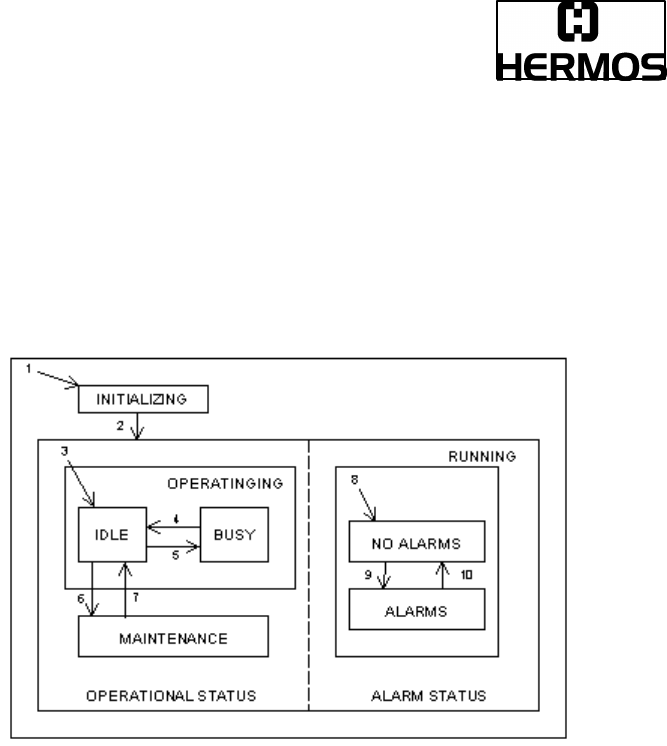
8.3.2 State Models
To facilitate independent control of the individual heads, there are two separate
state models defined, one for CIDRW subsystem and one for each individual head.
The HERMOS SECS-1 reader combines the CIDRW subsystem and the head
together.
The state model for the HERMOS reader is shown in the state model.

RS232-Transponder Reader
(SECS1-Protocol), Release 0.3 Draft Page 64 of 91
2000-09-29
ID: ID000093
The shown table defines the states of the HERMOS SECS-1 transponder reader.
State Definition
ALARM STATUS Shows the presence or absence of alarms.
ALARMS An alarm condition exists.
BUSY A service is being performed that affects the state of
the hardware
CIDWR Superstate of CIDRW state model. Always active
when CIDRW powered on.
IDLE No service is being performed. All heads are idle.
INITIALIZING CIDRW is performing initialization and self
diagnostic. Presence or absence of alarms is initially
determined in this state.
NO ALARMS No alarm condition exists.
OPERATING Normal operational states where reading and/or
writing operations can be performed
OPERATIONAL STATUS The CIDRW is fully capable of performing all
services that it supports.
RUNNING The CIDRW is operational and able to communicate.
MAINTENANCE Internal setup and maintenance activities.

RS232-Transponder Reader
(SECS1-Protocol), Release 0.3 Draft Page 65 of 91
2000-09-29
ID: ID000093
The shown table defines the transitions of the HERMOS SECS-1 transponder
reader state model.
#
Previous
State Trigger New State Actions
Comment
1
Any Powerup or reset INITIALIZING Initialize
hard- and
software
Default entry on
powerup
2
INITIALIZING Initialization is
complete RUNNING None The CIDRW is now
able to communicate
3
INITIALIZING Default entry into
OPERATING IDLE None Internal
4
IDLE
A service request
to read or write or
perform
diagnostic
is received.
BUSY None
5
BUSY All services
request that affect
IDLE None
6
IDLE
A user selects the
MAINTENANCE
state and all
heads are IDLE
MAINTENANCE
None
The upstream
controller may send
a request or the
operator may set a
switch to select the
MAINTENANCE
state. Maintenance
and setup activities
may now be
performed.
7
MAINTENANCE
A user selects the
OPERATING
state and all
heads are IDLE
IDLE None
The upstream
controller may send
a request or the
operator may set a
switch to select the
OPERATING state.
Normal operating
activities may now be
performed.
8
INITIALIZING Default entry into
ALARM STATUS ALARMS or
NO ALARMS None
9
NO ALARMS An alarm
condition is
detected. ALARMS None
10
ALARMS All alarm
conditions have
cleared. NO ALARMS None
11
Any A reset service
request is received
CIDRW None

RS232-Transponder Reader
(SECS1-Protocol), Release 0.3 Draft Page 66 of 91
2000-09-29
ID: ID000093
9 MESSAGE DETAILS
9.1 Equipment status
9.1.1 S1F0: ABORT TRANSACTION (reader <-> host)
Used in lieu of an expected reply to abort a transaction. Function 0 is defined in
every stream and has the same meaning in every stream.
S1F0 W . * Header Only
9.1.2 S1F1: ARE YOU THERE REQUEST ( reader <-> host, reply )
Establishes if the gateway or host is online.
S1F1 W . * Header Only
9.1.3 S1F2: ON-LINE DATA ( host -> reader )
The host signifies that it is online.
S1F2
<L[2]
<A[6] MDLN >
<A[6] SOFTREV >
>.
9.1.4 S1F2: ON-LINE ( reader -> host )
The gateway signifies that it is online.
S1F2
<L[2]
<A[6] MDLN >
<A[6] SOFTREV >
>.
9.1.5 S1F15: REQUEST OFF_LINE ( host ->reader, reply )
The reader should change the communication state to offline.
The reader can only be put online again by message S1F17 (or reset S2F19), and
the other messages are aborted by the SxF0 message !
S1F15 W. *Header Only

RS232-Transponder Reader
(SECS1-Protocol), Release 0.3 Draft Page 67 of 91
2000-09-29
ID: ID000093
9.1.6 S1F16: OFFLINE ACKNOWLEDGE ( reader -> host )
Acknowledge.
S1F16
<B[1] OFLACK>.
9.1.7 S1F17: REQUEST ON_LINE ( host ->reader, reply )
The reader should change the communication state to online.
S1F17 W. *Header Only
9.1.8 S1F18: ONLINE ACKNOWLEDGE ( reader -> host )
Acknowledge.
S1F18
<B[1] ONLACK>.

RS232-Transponder Reader
(SECS1-Protocol), Release 0.3 Draft Page 68 of 91
2000-09-29
ID: ID000093
9.2 Equipment Control
9.2.1 S2F0: ABORT TRANSACTION (reader <-> host)
Used in lieu of an expected reply to abort a transaction. Function 0 is defined in
every stream and has the same meaning in every stream.
S2F0 W . * Header Only
9.2.2 S2F13: EQUIPMENT CONSTANT REQUEST (host-> reader , reply)
The host requests one constant from the gateway or reader.
S2F13 W
<L[1]
<U1[1] ECID>
>.
9.2.3 S2F14: EQUIPMENT CONSTANT DATA (reader -> host )
The reader sends the requested constant to the host.
S2F14
<L[1]
<U1[1] ECV>
>.
9.2.4 S2F15: NEW EQUIPMENT CONSTANT SEND
( host-> reader, reply )
The host changes one reader constant.
S2F15 W
<L[1]
<L[2]
<U1[1] ECID>
<U1[1]ECV>
>
>.

RS232-Transponder Reader
(SECS1-Protocol), Release 0.3 Draft Page 69 of 91
2000-09-29
ID: ID000093
9.2.5 S2F16: NEW EQUIPMENT CONSTANT ACKNOWLEDGE
(reader -> host )
The reader acknowledges the new host constant.
S2F16
<B[1] EAC>.
9.2.6 S2F19: RESET SEND ( host -> reader, reply )
The host requests the reader to reset the hard- and software.
In both cases there will be a communication inquiry with S1F1.
The powerup reset requires a few seconds.
S2F19 W
<B[1] RIC>.
9.2.7 S2F20: RESET ACKNOWLEDGE (reader -> host )
The reader acknowledges the reset.
In case of a powerup-reset, the S2F20 message requires a few seconds.
S2F20
<B[1] RAC>.

RS232-Transponder Reader
(SECS1-Protocol), Release 0.3 Draft Page 70 of 91
2000-09-29
ID: ID000093
9.3 Material Status
9.3.1 S3F0: ABORT TRANSACTION (reader <-> host)
Used in lieu of an expected reply to abort a transaction. Function 0 is defined in
every stream and has the same meaning in every stream.
S3F0 W . * Header Only
9.3.2 S3F5: CASSETTE FOUND SEND ( reader -> host, reply )
The reader sends the information that a cassette was detected by the sensor.
This message will only be sent, if a sensor is connected and activated (see
‘watchport’ and ‘sensor activity’).
S3F5 W.
<L[2]
<B[1] MF>
<B[1] PTN>
>
9.3.3 S3F6: CASSETTE FOUND ACKNOWLEDGE ( host -> reader)
The host acknowledges the cassette found message.
S3F6
<B[1] ACKC3>.

RS232-Transponder Reader
(SECS1-Protocol), Release 0.3 Draft Page 71 of 91
2000-09-29
ID: ID000093
9.3.4 S3F7: CASSETTE LOST SEND ( reader -> host, reply )
The reader sends the information that the cassette was removed from I/O port
(sensor).
This message will only be sent, if a sensor is connected and activated (see
‘watchport’ and ‘sensor activity’). The PAGEDATA can only be given, if the
PAGEDATA read at last is still known.
S3F7 W.
<L[3]
<B[1] MF >
<B[1] PTN >
<B[9] PAGEDATA > * a zero-length PAGEDATA indicates that no
PAGEDATA is available (case of error)
>
9.3.5 S3F8: CASSETTE LOST ACKNOWLEDGE ( host -> reader )
The host acknowledges the cassette lost message.
S3F8
<B[1] ACKC3>
9.3.6 S3F11: READ MID AT I/O PORT (host ->reader , reply )
The host requests that the reader reads the PAGEDATA.
S3F11 W
<B[1] PAGE_ID>

RS232-Transponder Reader
(SECS1-Protocol), Release 0.3 Draft Page 72 of 91
2000-09-29
ID: ID000093
9.3.7 S3F12: READ ACKNOWLEDGE ( reader -> host )
The reader only acknowledges the receipt of the reading command.
The reading ID will be sent later!
S3F12
<L[3]
<B[1] PTN> * a zero-length PTN indicates that no PTN is available
<B[1] MIDRA>
<B[9] PAGEDATA> * a zero-length PAGEDATA indicates that no
DATA is available
>.
9.3.8 S3F13: RETURN READ MID ( reader -> host, reply )
The reader sends the ID of the cassette at the I/O port to the host.
S3F13 W
<L[2]
<B[1] PTN>
<B[9] PAGEDATA >
>.
9.3.9 S3F14: MID ACKNOWLEDGE ( host -> reader )
The host acknowledges the received data.
S3F14
<B[1] MIDAC>.
9.3.10 S3F65: WRITE MID AT I/O PORT ( host -> reader, reply )
The host requests that the reader writes the PAGEDATA.
S3F65 W
<B[9] PAGEDATA >

RS232-Transponder Reader
(SECS1-Protocol), Release 0.3 Draft Page 73 of 91
2000-09-29
ID: ID000093
9.3.11 S3F66: WRITE ACKNOWLEDGE ( reader -> host )
The reader only acknowledges the receipt of the writing command.
The writing acknowledge will be sent later!
S3F66
<L[2]
<B[1] MIDRA>
<B[9] PAGEDATA >
>.
9.3.12 S3F67: RETURN WRITE SUCCESS ( reader -> host, reply )
The reader reports the successful writing of the transponder. The reader sends
information about sensor 0.
S3F67 W
<B[1] PTN>.
9.3.13 S3F68: WRITE SUCCESS ACKNOWLEDGE ( host -> reader)
The host acknowledges the received data.
S3F68
<B[1] MIDAC>.
9.3.14 S3F73: LOCK MID AT I/O PORT ( host -> reader, reply )
The host requests that the reader lockes the wanted page.
S3F73 W
<B[1] PAGE_ID>.
9.3.15 S3F74: LOCK ACKNOWLEDGE ( reader -> host )
The reader only acknowledges the receipt of the locking command.
The locking acknowledge will be sent later!
S3F74
<L[2]
<B[1] MIDRA>
<B[9] PAGEDATA >
>.

RS232-Transponder Reader
(SECS1-Protocol), Release 0.3 Draft Page 74 of 91
2000-09-29
ID: ID000093
9.3.16 S3F75: RETURN LOCK SUCCESS ( reader -> host, reply )
The reader reports the successful writing of the transponder. The reader sends
information about sensor 0.
S3F75 W
<B[1] PTN>.
9.3.17 S3F76: LOCK SUCCESS ACKNOWLEDGE ( host -> reader)
The host acknowledges the received lock success message (S3F67).
S3F76
<B[1] MIDAC>.

RS232-Transponder Reader
(SECS1-Protocol), Release 0.3 Draft Page 75 of 91
2000-09-29
ID: ID000093
9.4 Exception Handling
9.4.1 S5F0: ABORT TRANSACTION (reader <-> host)
Used in lieu of an expected reply to abort a transaction. Function 0 is defined in
every stream and has the same meaning in every stream.
S5F0 W . * Header Only
9.4.2 S5F1: GATEWAY READER ALARM REPORT SEND
(reader -> host, reply )
The reader reports all errors to the host.
S5F1 W
<L[3]
<B[1] ALCD > * alarm code byte
<U1[1] ALID > * alarm ID
<A[MAX 40] ALTX > * alarm text
> .
9.4.3 S5F2: ALARM REPORT ACKNOWLEDGE (host-> reader)
The host acknowledges an alarm.
S5F2
<B[1] MIDAC>.

RS232-Transponder Reader
(SECS1-Protocol), Release 0.3 Draft Page 76 of 91
2000-09-29
ID: ID000093
9.5 System Errors
9.5.1 S9F1: UNRECOGNIZED DEVICE ID ( reader -> host )
The device-ID in the message block header did not correspond to the equipment
device ID’s.
S9F1
<B[10] MHEAD > .
9.5.2 S9F3: UNRECOGNIZED STREAM TYPE (reader -> host )
The reader does not recognize the stream type in the message block header.
S9F3
<B[10] MHEAD > .
9.5.3 S9F5: UNRECOGNIZED FUNCTION TYPE (reader -> host )
The reader does not recognize the function number in the message block header.
S9F5
<B[10] MHEAD > .
9.5.4 S9F7: ILLEGAL DATA (reader -> host )
The reader does not recognize the data in the message block header.
S9F5
<B[10] MHEAD > .
9.5.5 S9F9: TRANSACTION TIMER TIME-OUT ( reader -> host )
This message indicates that a transaction timer has timed out and that the
corresponding transaction has been aborted. Only the last sent message which has
to be confirmed by the host is stored and controlled.
S9F9
<B[10] SHEAD > .

RS232-Transponder Reader
(SECS1-Protocol), Release 0.3 Draft Page 77 of 91
2000-09-29
ID: ID000093
9.6 Subsystem Control and Data
9.6.1 S18F1: READ ATTRIBUTE REQUEST (RAR) (host -> reader, reply)
This message requests the current values of specified attributes of the subsystem
component indicated in TARGETID.
S18F1 W
L,2
1. A,8 <TARGETID>
2. L,n 1. <ATTRID1>
…
n. <ATTRIDn>
If n=0 then all attributes of the target component are requested.
9.6.2 S18F2: READ ATTRIBUTE DATA (RAD) (reader -> host)
This message returns the current values of requested attributes and the current
status of the requested component indicated in TARGETID.
S18F2
L,4 1. A,8 <TARGETID>
2. A,2 <SSACK>
3. L,n 1. <ATTRVAL1>
…
n. <ATTRVALn>
4. L,s 1. <STATUS1>
…
s. <STATUSs>
Both n=0 and s=0 if the target component is unknown.

RS232-Transponder Reader
(SECS1-Protocol), Release 0.3 Draft Page 78 of 91
2000-09-29
ID: ID000093
9.6.3 S18F3: WRITE ATTRIBUTE REQUEST (WAR) (host -> reader, reply)
This message requests the subsystem to set the value of read/write attributes of the
component specified in TARGETID.
S18F3 ,W
L,2 1. A,8 <TARGETID>
2. L,n
1. L,2
1. <ATTRID1>
2. <ATTRVAL1>
…
n. L,2
1. <ATTRIDn>
2. <ATTRVALn>
9.6.4 S18F4: WRITE ATTRIBUTE ACKNOWLEDGE (WAA) (reader -> host)
This message acknowledges the success of failure of the request to write attribute
data to the subsystem indicated in TARGETID.
S18F4
L,3 1. A,8 <TARGETID>
2. A,2 <SSACK>
3. L,s 1. <STATUS1>
…
s. <STATUSs>
s=0 if the target component is unknown

RS232-Transponder Reader
(SECS1-Protocol), Release 0.3 Draft Page 79 of 91
2000-09-29
ID: ID000093
9.6.5 S18F5: READ REQUEST (RR) (host -> reader, reply)
The host requests the subsystem indicated in TARGETID to read information.
DATASEG may be used to indicate a specific section of data to be read.
DATALENGTH is used to limit the amount of data for that section.
S18F5 W
L,3
1. A,8 <TARGETID>
2. A,2 <DATASEG>
3. UI2 <DATALENGTH>
If DATASEG and DATALENGTH are both omitted (zero length items) then all data
is requested. If only DATALENGTH is omitted, then all data within the indicated
section are requested.
9.6.6 S18F6: READ DATA (RD) (reader -> host)
This message is used to return requested information from the subsystem indicated
in TARGETID or to acknowledge the result of the request.
S18F6
L,3
1. A,8 <TARGETID>
2. A,2 <SSACK>
3. A,8 <DATA>
If TARGETID is unknown, then DATA is zero length.
9.6.7 S18F7: WRITE DATA REQUEST (WAR) (host -> reader, reply)
This message requests to write data to the subsystem component indicated in
TARGETID. DATASEG may be used to indicate a specific section of data to be
written or overwritten.
S18F7 W
L,4
1. A,8 <TARGETID>
2. A,2 <DATASEG>
3. UI2 <DATALENGTH>
4. A,8 <DATA>

RS232-Transponder Reader
(SECS1-Protocol), Release 0.3 Draft Page 80 of 91
2000-09-29
ID: ID000093
If DATASEG and DATALENGTH are both omitted (zero length items) then all data
is to be overwritten. If only DATALENGTH is omitted or if DATALENGTH has a
value of zero, then all data within the indicated section are to be written.
9.6.8 S18F8: WRITE DATA ACKNOWLEDGE (WDA) (reader -> host)
This message acknowledges the success or failure of writing data to the subsystem
indicated in TARGETID.
S18F8
L,3
1. A,8 <TARGETID>
2. A,2 <SSACK>
3. L,s
1. <STATUS1>
…
s. <STATUSs>
s=0 if TARGETID is unknown
9.6.9 S18F9: READ ID REQUEST (RIR) (host -> reader, reply)
This message is used to request the subsystem indicated by TARGETID to read an
identifier.
S18F9,W
L,3 1. A,8 <TARGETID>
9.6.10 S18F10: READ ID DATA (RID) (reader -> host)
This message returns a requested material identifier MID as read by the subsystem
indicated in TARGETID.
S18F10
L,4 1. A,8 <TARGETID>
2. A,2 <SSACK>
3. A,8 <MID>
4. L,s 1. <STATUS1>
…
s. <STATUSs>
s=0 if and only if TARGETID is unknown.

RS232-Transponder Reader
(SECS1-Protocol), Release 0.3 Draft Page 81 of 91
2000-09-29
ID: ID000093
9.6.11 S18F11: WRITE ID REQUEST (WIR) (host -> reader, reply)
This message is used to request the subsystem indicated by TARGETID to write an
identifier.
S18F11 W
L,2
1. A,8 <TARGETID>
2. A,8 <MID>
9.6.12 S18F12: WRITE ID ACKNOWLEDGE (WIA) (reader -> host)
This message acknowledges the success or failure of writing the ID to the
subsystem indicated in TARGETID.
S18F12
L,3 1. A,8 <TARGETID>
2. A,2 <SSACK>
3. L,s 1. <STATUS1>
…
s. <STATUSs>
s=0 if TARGETID is unknown
9.6.13 S18F13: SUBSYSTEM COMMAND REQUEST (SCR)
(host -> reader, reply)
This message is used to request the subsystem indicated in TARGETID to perform
a specific action.
S18F13 W
L,2
1. A,8 <TARGETID>
2. A,18 <SSCMD>
3. L,n 1. <CPVAL>
…
n. <CPVALn>
If n=0 no parameters are provided.

RS232-Transponder Reader
(SECS1-Protocol), Release 0.3 Draft Page 82 of 91
2000-09-29
ID: ID000093
9.6.14 S18F14: SUBSYSTEM COMMAND ACKNOWLEDGE (SCA)
(reader -> host)
This message reports the result from the subsystem specified in TARGETID for the
requested action.
S18F14
L,3 1. A,8 <TARGETID>
2. A,2 <SSACK>
3. L,s 1. <STATUS1>
…
t. <STATUSs>
s=0 if and only if TARGETID is unknown.

RS232-Transponder Reader
(SECS1-Protocol), Release 0.3 Draft Page 83 of 91
2000-09-29
ID: ID000093
10 SECS-1 MESSAGE EXAMPLES
All examples are produced with the default gateway-ID 255 (decimal) or 0x00FF
(hexadecimal) !
1. S1F1 Message from the reader to the host
Gateway to Host: S1F1
16:54:47 Incoming: ENQ ( 05 )
16:54:47 Outgoing: EOT ( 04 )
16:54:47 Incoming: Length Byte ( 0A )
16:54:47 Incoming: Header ( 81 FF 81 01 80 01 00 00 00 01 )
16:54:47 Incoming: Checksum ( 02 84 )
16:54:47 Outgoing: ACK ( 06 )
Host to Gateway: S1F2
16:54:48 Outgoing: ENQ ( 05 )
16:54:48 Incoming: EOT ( 04 )
16:54:48 Outgoing: Length Byte ( 10 )
16:54:48 Outgoing: Header ( 01 FF 01 02 80 01 00 00 00 01 )
16:54:48 Outgoing: Data ( 01 02 41 00 41 00 )
16:54:48 Outgoing: Checksum ( 09 03 )
16:54:48 Incoming: ACK ( 06 )
2. S1F1 Message from the host to the reader
Host to Reader: S1F1
16:59:20 Outgoing: ENQ ( 05 )
16:59:20 Incoming: EOT ( 04 )
16:59:20 Outgoing: Length Byte ( 0A )
16:59:20 Outgoing: Header ( 01 FF 81 01 80 01 00 00 00 01 )
16:59:20 Outgoing: Checksum ( 03 03 )
16:59:20 Incoming: ACK ( 06 )
Reader to Host: S1F2
16:59:20 Incoming: ENQ ( 05 )
16:59:20 Outgoing: EOT ( 04 )
16:59:20 Incoming: Length Byte ( 1C )
16:59:20 Incoming: Header ( 81 FF 01 02 80 01 00 00 00 01 )
16:59:20 Incoming: Data ( 01 02 41 06 67 61 74 65 53 32 41 06 56 )
16:59:20 Incoming: Data ( 31 2E 31 2E 30 )
16:59:20 Incoming: Checksum ( 06 00 )
16:59:20 Outgoing: ACK ( 06 )

RS232-Transponder Reader
(SECS1-Protocol), Release 0.3 Draft Page 84 of 91
2000-09-29
ID: ID000093
3. Message S1F15 sets the reader offline
Host to Reader: S1F15
17:06:57 Outgoing: ENQ ( 05 )
17:06:57 Incoming: EOT ( 04 )
17:06:57 Outgoing: Length Byte ( 0A )
17:06:57 Outgoing: Header ( 01 FF 81 0F 80 01 00 00 00 03 )
17:06:57 Outgoing: Checksum ( 13 03 )
17:06:57 Incoming: ACK ( 06 )
Reader to Host: S1F16
17:06:57 Incoming: ENQ ( 05 )
17:06:57 Outgoing: EOT ( 04 )
17:06:57 Incoming: Length Byte ( 0D )
17:06:57 Incoming: Header ( 81 FF 01 10 80 01 00 00 00 03 )
17:06:57 Incoming: Data ( 21 01 00 )
17:06:57 Incoming: Checksum ( 02 37 )
17:06:57 Outgoing: ACK ( 06 )
4. Message S1F17 sets the reader online
Host to Reader: S1F17
17:10:00 Outgoing: ENQ ( 05 )
17:10:00 Incoming: EOT ( 04 )
17:10:00 Outgoing: Length Byte ( 0A )
17:10:00 Outgoing: Header ( 01 FF 81 11 80 01 00 00 00 05 )
17:10:00 Outgoing: Checksum ( 17 03 )
17:10:00 Incoming: ACK ( 06 )
Reader to Host: S1F18
17:10:00 Incoming: ENQ ( 05 )
17:10:00 Outgoing: EOT ( 04 )
17:10:00 Incoming: Length Byte ( 0D )
17:10:00 Incoming: Header ( 81 FF 01 12 80 01 00 00 00 05 )
17:10:00 Incoming: Data ( 21 01 00 )
17:10:00 Incoming: Checksum ( 02 3B )
17:10:00 Outgoing: ACK ( 06 )

RS232-Transponder Reader
(SECS1-Protocol), Release 0.3 Draft Page 85 of 91
2000-09-29
ID: ID000093
5. Request reader constant with message S2F13
Host to Reader (Gateway): S2F13
17:21:37 Outgoing: ENQ ( 05 )
17:21:37 Incoming: EOT ( 04 )
17:21:37 Outgoing: Length Byte ( 0F )
17:21:37 Outgoing: Header ( 01 FF 82 0D 80 01 00 00 00 08 )
17:21:37 Outgoing: Data ( 01 01 21 01 05 ) => parameter „5“
17:21:37 Outgoing: Checksum ( 41 02 )
17:21:37 Incoming: ACK ( 06 )
Reader to Host: S2F14
17:21:37 Incoming: ENQ ( 05 )
17:21:37 Outgoing: EOT ( 04 )
17:21:37 Incoming: Length Byte ( 0F )
17:21:37 Incoming: Header ( 81 FF 02 0E 80 01 00 00 00 08 )
17:21:37 Incoming: Data ( 01 01 A5 01 14 ) => parameter „5“ and the value „20“
17:21:37 Incoming: Checksum ( 02 D5 )
17:21:37 Outgoing: ACK ( 06 )
The host requests the reader parameter „25“ (r/w maxrepeat).
Reader1 (gateway) sends the value „20“ from parameter „25“ .
6. New Reader constant send with S2F15
Host to Reader: S2F15
17:41:53 Outgoing: ENQ ( 05 )
17:41:53 Incoming: EOT ( 04 )
17:41:53 Outgoing: Length Byte ( 14 )
17:41:53 Outgoing: Header ( 01 FF 82 0F 80 01 00 00 00 0C )
17:41:53 Outgoing: Data ( 01 01 01 02 A5 01 07 A5 01 03 ) =>
parameter „7“ , value „3“
17:41:53 Outgoing: Checksum ( 7A 01 )
17:41:53 Incoming: ACK ( 06 )

RS232-Transponder Reader
(SECS1-Protocol), Release 0.3 Draft Page 86 of 91
2000-09-29
ID: ID000093
Reader to Host: S2F16
17:41:53 Incoming: ENQ ( 05 )
17:41:53 Outgoing: EOT ( 04 )
17:41:54 Incoming: Length Byte ( 0D )
17:41:54 Incoming: Header ( 81 FF 02 10 80 01 00 00 00 0C )
17:41:54 Incoming: Data ( 21 01 00 ) => setting was successful
17:41:54 Incoming: Checksum ( 02 41 )
17:41:54 Outgoing: ACK ( 06 )
The Host sets the reader2 parameter „7“ (watchport) with the value „3“.
Reader2 acknowledges the new constant.
7. Host requests a reader reset with S2F19
Host to Reader: S2F19
17:58:22 Outgoing: ENQ ( 05 )
17:58:22 Incoming: EOT ( 04 )
17:58:22 Outgoing: Length Byte ( 0D )
17:58:22 Outgoing: Header ( 01 FF 82 13 80 01 00 00 00 13 )
17:58:22 Outgoing: Data ( 21 01 01 )
17:58:22 Outgoing: Checksum ( 4E FF )
17:58:22 Incoming: ACK ( 06 )
Reader to Host: S2F20
17:58:23 Incoming: ENQ ( 05 )
17:58:23 Outgoing: EOT ( 04 )
17:58:23 Incoming: Length Byte ( 0D )
17:58:23 Incoming: Header ( 81 FF 02 14 80 01 00 00 00 13 )
17:58:23 Incoming: Data ( 21 01 00 )
17:58:23 Incoming: Checksum ( 02 4C )
17:58:23 Outgoing: ACK ( 06 )
8. The reader sends the message S3F5 after the sensor detects a cassette
Reader to Host: S3F5
19:39:15 Incoming: ENQ ( 05 )
19:39:15 Outgoing: EOT ( 04 )
19:39:15 Incoming: Length Byte ( 12 )
19:39:15 Incoming: Header ( 81 FF 83 05 80 01 00 01 00 09 )
19:39:15 Incoming: Data ( 01 02 )
19:39:15 Incoming: Data ( 21 01 14 ) ->Initiator=1, Sensor 0=0, Sensor 1=1
19:39:15 Incoming: Data ( 21 01 48 )
19:39:15 Incoming: Checksum ( 03 36 )
19:39:15 Outgoing: ACK ( 06 )

RS232-Transponder Reader
(SECS1-Protocol), Release 0.3 Draft Page 87 of 91
2000-09-29
ID: ID000093
Host to Reader: S3F6
19:39:15 Outgoing: ENQ ( 05 )
19:39:15 Incoming: EOT ( 04 )
19:39:15 Outgoing: Length Byte ( 0D )
19:39:15 Outgoing: Header ( 01 FF 03 06 80 01 00 01 00 09 )
19:39:15 Outgoing: Data ( 21 01 01 ) ->Sensor 1 Acknowledge
19:39:15 Outgoing: Checksum ( B7 01 )
19:39:15 Incoming: ACK ( 06 )
9. The reader sends the message S3F13 after the sensor was detected and the
transponder could be read
Reader to Host: S3F13
19:39:15 Incoming: ENQ ( 05 )
19:39:15 Outgoing: EOT ( 04 )
19:39:15 Incoming: Length Byte ( 1A )
19:39:15 Incoming: Header ( 81 FF 83 0D 80 01 00 01 00 0A )
19:39:15 Incoming: Data ( 01 02 )
19:39:15 Incoming: Data ( 21 01 48 ) ->Initiator=1, Sensor 0=0, Sensor 1=1
19:39:15 Incoming: Data ( 21 09 F1 ) ->Page=241 (Read/Write-Transponder)
19:39:15 Incoming: Data ( 11 11 ) ->ID=“17 17 17 17 17 17 17 17“ (decimal)
19:39:15 Incoming: Data ( 11 11 11 )
19:39:15 Incoming: Data ( 11 11 11 )
19:39:16 Incoming: Checksum ( 04 AC )
19:39:16 Outgoing: ACK ( 06 )
Host to Reader: S3F14
19:39:16 Outgoing: ENQ ( 05 )
19:39:16 Incoming: EOT ( 04 )
19:39:16 Outgoing: Length Byte ( 0D )
19:39:16 Outgoing: Header ( 01 FF 03 0E 80 01 00 01 00 0A )
19:39:16 Outgoing: Data ( 21 01 01 ) ->Sensor 1 Acknowledge
19:39:16 Outgoing: Checksum ( C0 01 )
19:39:16 Incoming: ACK ( 06 )
The material-ID-acknowledge MIDAC depends on the sensorstate PTN. The
initiator was the sensor 0 and the host acknowledges with „0“.

RS232-Transponder Reader
(SECS1-Protocol), Release 0.3 Draft Page 88 of 91
2000-09-29
ID: ID000093
10. The reader sends the message S3F7 after the cassette was removed from
the sensor.
Reader to Host: S3F7
19:39:17 Incoming: ENQ ( 05 )
19:39:17 Outgoing: EOT ( 04 )
19:39:17 Incoming: Length Byte ( 1D )
19:39:17 Incoming: Header ( 81 FF 83 07 80 01 00 01 00 0B )
19:39:17 Incoming: Data ( 01 03)
19:39:17 Incoming: Data ( 21 01 14 )
19:39:17 Incoming: Data ( 21 01 40 ) ->Initiator=1, Sensor 0=0, Sensor 1=0
19:39:17 Incoming: Data ( 21 09 F1 ) ->Page=241
19:39:17 Incoming: Data ( 11 11 11 ) ->ID=“17 17 17 17 17 17 17 17“ (decimal)
19:39:17 Incoming: Data ( 11 11 11 )
19:39:17 Incoming: Data ( 11 11 )
19:39:17 Incoming: Checksum ( 04 D6 )
19:39:17 Outgoing: ACK ( 06 )
Host to Reader: S3F8
19:39:17 Outgoing: ENQ ( 05 )
19:39:17 Incoming: EOT ( 04 )
19:39:17 Outgoing: Length Byte ( 0D )
19:39:17 Outgoing: Header ( 01 FF 03 08 80 01 00 01 00 0B )
19:39:17 Outgoing: Data ( 21 01 01 ) ->Sensor 1 Acknowledge
19:39:17 Outgoing: Checksum ( BB 01 )
19:39:17 Incoming: ACK ( 06 )
11. The reader detects an unrecognized device-ID and sends the message
S9F1.
Host to Reader: S1F1
08:17:16 Outgoing: ENQ ( 05 )
08:17:16 Incoming: EOT ( 04 )
08:17:16 Outgoing: Length Byte ( 0A )
08:17:16 Outgoing: Header ( 01 D2 81 01 80 01 00 00 00 03 )
08:17:16 Outgoing: Checksum ( D9 02 )
08:17:16 Incoming: ACK ( 06 )

RS232-Transponder Reader
(SECS1-Protocol), Release 0.3 Draft Page 89 of 91
2000-09-29
ID: ID000093
Reader to Host: S9F1
08:17:16 Incoming: ENQ ( 05 )
08:17:16 Outgoing: EOT ( 04 )
08:17:16 Incoming: Length Byte ( 16 )
08:17:16 Incoming: Header ( 81 FF 09 01 80 01 00 00 00 04 )
08:17:16 Incoming: Data ( 21 0A 01 D2 81 )
08:17:16 Incoming: Data ( 01 80 01 00 00 00 03 )
08:17:16 Incoming: Checksum ( 04 12 )
08:17:16 Outgoing: ACK ( 06 )
The device-ID in the message block header did not correspond to the device-ID in
the reader detecting the error.
12. The reader detects a wrong stream number and sends the S9F3 message
Host to Reader: S4F1
20:03:20 Outgoing: ENQ ( 05 )
20:03:20 Incoming: EOT ( 04 )
20:03:20 Outgoing: Length Byte ( 0A )
20:03:20 Outgoing: Header ( 01 FF 84 01 80 01 00 00 00 08 )
20:03:20 Outgoing: Checksum ( 0E 02 )
20:03:20 Incoming: ACK ( 06 )
Reader to Host: S9F3
20:03:20 Incoming: ENQ ( 05 )
20:03:20 Outgoing: EOT ( 04 )
20:03:20 Incoming: Length Byte ( 16 )
20:03:20 Incoming: Header ( 81 FF 09 03 80 01 00 00 00 09 )
20:03:20 Incoming: Data ( 21 0A 01 FF 84 ) =>the wrong message header
20:03:20 Incoming: Data ( 01 80 01 00 00 00 08 )
20:03:20 Incoming: Checksum ( 04 4F )
20:03:20 Outgoing: ACK ( 06 )
The stream „4“ isn’t part of the SECS-2 message-set, so a S9F3 error message will
appear.

RS232-Transponder Reader
(SECS1-Protocol), Release 0.3 Draft Page 90 of 91
2000-09-29
ID: ID000093
13. The reader detects an unrecognized function and sends the message
S9F5.
Host to Reader: S1F3
19:54:43 Outgoing: ENQ ( 05 )
19:54:43 Incoming: EOT ( 04 )
19:54:43 Outgoing: Length Byte ( 0A )
19:54:43 Outgoing: Header ( 01 FF 81 03 80 01 00 00 00 06 )
19:54:43 Outgoing: Checksum ( 0B 02 )
19:54:43 Incoming: ACK ( 06 )
Reader to Host: S9F5
19:54:43 Incoming: ENQ ( 05 )
19:54:43 Outgoing: EOT ( 04 )
19:54:43 Incoming: Length Byte ( 16 )
19:54:43 Incoming: Header ( 81 FF 09 05 80 01 00 00 00 07 )
19:54:43 Incoming: Data ( 21 0A 01 FF 81 ) =>the wrong message header
19:54:43 Incoming: Data ( 03 80 01 00 00 00 06 )
19:54:43 Incoming: Checksum ( 04 4C )
19:54:43 Outgoing: ACK ( 06 )
The function „3“ is nt part of the SECSII-message-set, so a S9F5 error message will
appear.
14. The secondary message fails and the reader sends the S9F9 message
Reader to Host: S1F1
20:07:16 Incoming: ENQ ( 05 )
20:07:16 Outgoing: EOT ( 04 )
20:07:16 Incoming: Length Byte ( 0A )
20:07:16 Incoming: Header ( 81 FF 81 01 80 01 00 00 00 01 )
20:07:16 Incoming: Checksum ( 02 84 )
20:07:16 Outgoing: ACK ( 06 )

RS232-Transponder Reader
(SECS1-Protocol), Release 0.3 Draft Page 91 of 91
2000-09-29
ID: ID000093
Host to Reader: S9F9
20:08:01 Incoming: ENQ ( 05 )
20:08:01 Outgoing: EOT ( 04 )
20:08:01 Incoming: Length Byte ( 16 )
20:08:01 Incoming: Header ( 81 FF 09 09 80 01 00 00 00 02 )
20:08:01 Incoming: Data ( 21 0A 81 FF 81 ) =>the stored header
20:08:01 Incoming: Data ( 01 80 01 00 00 00 01 )
20:08:01 Incoming: Checksum ( 04 C3 )
20:08:01 Outgoing: ACK ( 06 )
After sending the S1F1 message, the reader waits for an answer from host.
If the secondary message will not appear, a transaction timeout arises and the
reader sends the S9F9 message.