Brother Dh4 B980 Users Manual S91980 302
Brother-Db2-B797-Owner-S-Manual brother-db2-b797-owner-s-manual
Dh4-B980 Instructions DH4-B980 INSTRUCTIONS DH4-B980 INSTRUCTIONS BROTHER a.teamworksales.com
Rh-9800 Instructions RH-9800 INSTRUCTIONS RH-9800 INSTRUCTIONS BROTHER a.teamworksales.com
DH4-B980 to the manual 87392bf9-21de-422b-b248-9a00b5c81dc1
2015-01-25
: Brother Brother-Dh4-B980-Users-Manual-213499 brother-dh4-b980-users-manual-213499 brother pdf
Open the PDF directly: View PDF ![]() .
.
Page Count: 66
- COVER-A
- PL
- CONTENTS
- 1. NAMES OF EACH PART
- 2. SPECIFICATIONS
- 3. INSTALLATION
- 3-1. Table processing diagram
- 3-2. Installing the motor
- 3-3. Installing the machine head
- 3-4. Installing the oil container
- 3-5. Installing the spool stand
- 3-6. Tightening the V-belt
- 3-7. Installing the control box
- 3-8. Installing the air unit and the valve assembly
- 3-9. Connecting the ground wires and the wirings
- 3-10. Connecting the air tubes
- 3-11. Installing the air hoses
- 3-12. Connecting the power cord
- 4. LUBRICATION
- 5. CORRECT USE
- 6. USING THE OPERATION PANEL AND FRONT PANEL
- 6-1. Panel button and switch names
- 6-2. Selecting a program number
- 6-3. Changing the mode
- 6-4. Changing the cutting timing
- 6-5. Setting a program
- A.Setting the sewing speed
- B.Setting the shape of the eyelet
- C.Setting the buttonhole length
- D.Setting the tacking length
- E.Setting the offset
- F. Setting the stitch pitch
- G. Setting the number of eyelet stitches
- H. Setting the cutting space
- I. Setting the knife position compensation
- P1. Setting X correction
- P2. Setting Y correction
- P3.Setting θ1 correction
- P4. Setting θ 2 correction
- 6-6. Using the memory switch
- 6-7. List of error codes
- 7. SEWING
- 7-1. Using the EMERGENCY STOP switch
- 7-2. Sewing
- 7-3. Adjusting the thread tension
- 7-4. Needle and knife position
- 7-5. Using the production counter
- 7-6. Using a cycle program
- 7-7. Setting the feed bracket to the front position
- 7-8. Switching between single-pedal and dual-pedal operation (Switching the foot controller)
- 7-9. Using feed mode
- 7-10. Using manual mode
- 7-11. Changing the cycle program counter
- 7-12. Setting the number of home position cycles
- 7-13. Returning to the home position
- 8. CLEANING AND MAINTENANCE
- 9. STANDARD ADJUSTMENTS
- 9-1. Adjusting the height of the spreader and looper
- 9-2. Adjusting the needle and looper timing
- 9-3. Adjusting the loop stroke
- 9-4. Adjusting the height of the needle bar
- 9-5. Adjusting the clearance between the looper and needle
- 9-6. Adjusting the needle guard
- 9-7. Adjusting the spreader mounting positions
- 9-8. Adjusting the spreader timing
- 9-9. Adjusting the needle racking width (stitch width)
- 9-10.Changing the knife cutting length (Replacing the cutting block)
- 9-11. Adjusting the contact between the knife and the cutting block
- 9-12. Replacing the knife
- 9-13. Adjusting the cutting pressure
- 9-14. Adjusting the cloth opening amount
- 9-15. Adjusting the trimming of the upper thread
- 9-16. Adjusting the trimming of the lower thread and gimp
- 9-17. Adjusting the gimp length after trimming (-02)
- 9-18. Lower thread presser (-02)
- 9-19. Sub presser (-02)
- 10. SUMMARY OF DIP SWITCHES
- 11. TROUBLESHOOTING
- COVER-B

DH4-B980
RH-9800
Please read this manual before using the machine.
Please keep this manual within easy reach for quick reference.
ELECTRONIC EYELET BUTTON HOLER
INSTRUCTION MANUAL
RH-9800
i
Thank you very much for buying a BROTHER sewing machine. Before using your new machine, please read the safety
instructions below and the explanations given in the instruction manual.
With industrial sewing machines, it is normal to carry out work while positioned directly in front of moving parts such as
the needle and thread take-up lever, and consequently there is always a danger of injury that can be caused by these
parts. Follow the instructions from training personnel and instructors regarding safe and correct operation before
operating the machine so that you will know how to use it correctly.
SAFETY INSTRUCTIONS
1. Safety indications and their meanings
This instruction manual and the indications and symbols that are used on the machine itself are provided in order to
ensure safe operation of this machine and to prevent accidents and injury to yourself or other people.
The meanings of these indications and symbols are given below.
Indications
DANGER The instructions which follow this term indicate situations where failure to follow the
instructions will almost certainly result in death or severe injury.
CAUTION The instructions which follow this term indicate situations where failure to follow the
instructions could cause injury when using the machine or physical damage to
equipment and surroundings.
Symbols
........................................This symbol ( ) indicates something that you should be careful of. The
picture inside the triangle indicates the nature of the caution that must be
taken.
(For example, the symbol at left means “beware of injury”.)
........................................This symbol ( ) indicates something that you must not do.
........................................This symbol ( ) indicates something that you must do. The picture
inside the circle indicates the nature of the thing that must be done.
(For example, the symbol at left means “you must make the ground
connection”.)
RH-9800 ii
2. Notes on safety
DANGER
Wait at least 5 minutes after turnin
g
off the
p
ower switch and disconnectin
g
the
p
ower cord from the wall outlet
before o
p
enin
g
the face
p
late of the control box. Touchin
g
areas where hi
g
h volta
g
es are
p
resent can result in
severe injury.
CAUTION
Environmental requirements
Use the sewing machine in an area which is free
from sources of stron
g
electrical noise such as
high-frequency welders.
Sources of stron
g
electrical noise ma
y
cause
problems with correct operation.
Any fluctuations in the power supply voltage
should be within 10% of the rated voltage for
the machine.
Voltage fluctuations which are greater than this
may cause problems with correct operation.
The
p
ower su
pp
l
y
ca
p
acit
y
should be
g
reater than
the re
q
uirements for the sewin
g
machine’s
electrical consumption.
Insufficient
p
ower su
pp
l
y
ca
p
acit
y
ma
y
cause
problems with correct operation.
The
p
neumatic deliver
y
ca
p
abilit
y
should be
g
reater than the re
q
uirements for the sewin
g
machine's total air consumption.
Insufficient
p
neumatic deliver
y
ca
p
abilit
y
ma
y
cause problems with correct operation.
The ambient tem
p
erature should be within the
range of 5 to 35 during use.
Tem
p
eratures which are lower or hi
g
her than this
may cause problems with correct operation.
The relative humidit
y
should be within the ran
g
e of
45% to 85% durin
g
use, and no dew formation
should occur in any devices.
Excessivel
y
dr
y
or humid environments and dew
formation ma
y
cause
p
roblems with correct
operation.
Avoid exposure to direct sunlight during use.
Ex
p
osure to direct sunli
g
ht ma
y
cause
p
roblems
with correct operation.
In the event of an electrical storm, turn off the
p
ower and disconnect the
p
ower cord from the
wall outlet.
Li
g
htnin
g
ma
y
cause
p
roblems with correct
operation.
Installation
Machine installation should onl
y
be carried out b
y
a qualified technician.
Contact your Brother dealer or a qualified electrician
for any electrical work that may need to be done.
The sewin
g
machine wei
g
hs more than 87 k
g
.
The installation should be carried out b
y
two or
more people.
Do not connect the
p
ower cord until installation is
com
p
lete, otherwise the machine ma
y
o
p
erate if
the start switch is
p
ressed b
y
mistake, which could
result in injury.
Be sure to connect the
g
round. If the
g
round
connection is not secure, you run a high risk of
receiving a serious electric shock, and problems
with correct operation may also occur.
A
ll cords should be secured at least 25 mm awa
y
from an
y
movin
g
p
arts. Furthermore, do not
excessivel
y
bend the cords or secure them too
firml
y
with sta
p
les, otherwise there is the dan
g
er
that fire or electric shocks could occur.
Install the belt covers to the machine head and
motor.
If usin
g
a work table which has casters, the casters
should be secured in such a wa
y
so that the
y
cannot move.
Be sure to wear
p
rotective
g
o
gg
les and
g
loves
when handlin
g
the lubricatin
g
oil and
g
rease, so
that the
y
do not
g
et into
y
our e
y
es or onto
y
our
skin, otherwise inflammation can result.
Furthermore, do not drink the oil or eat the
g
rease
under an
y
circumstances, as the
y
can cause
vomiting and diarrhoea.
Keep the oil out of the reach of children.
RH-9800
iii
CAUTION
Sewing
This sewing machine should only be used by
operators who have received the necessary
training in safe use beforehand.
The sewin
g
machine should not be used for an
y
applications other than sewing.
Be sure to wear
p
rotective
g
o
gg
les when usin
g
the
machine.
If
g
o
gg
les are not worn, there is the dan
g
er that if a
needle breaks,
p
arts of the broken needle ma
y
enter your eyes and injury may result.
Turn off the power switch at the following times,
otherwise the machine ma
y
o
p
erate if the start
switch is
p
ressed b
y
mistake, which could result in
injury.
When threading the needle
When replacing the needle
When not usin
g
the machine and when leavin
g
the machine unattended
If usin
g
a work table which has casters, the casters
should be secured in such a wa
y
so that the
y
cannot move.
A
ttach all safet
y
devices before usin
g
the sewin
g
machine. If the machine is used without these
devices attached, injury may result.
Do not touch an
y
of the movin
g
p
arts or
p
ress an
y
ob
j
ects a
g
ainst the machine while sewin
g
, as this
ma
y
result in
p
ersonal in
j
ur
y
or dama
g
e to the
machine.
If an error occurs in machine o
p
eration, or if abnormal
noises or smells are noticed, immediatel
y
turn off the
p
ower switch. Then contact
y
our nearest Brother
dealer or a qualified technician.
If the machine develo
p
s a
p
roblem, contact
y
our
nearest Brother dealer or a qualified technician.
Cleaning
Turn off the
p
ower switch before carr
y
in
g
out
cleaning, otherwise the machine may operate if
the start switch is
p
ressed b
y
mistake, which could
result in injury.
Be sure to wear
p
rotective
g
o
gg
les and
g
loves
when handlin
g
the lubricatin
g
oil and
g
rease, so
that the
y
do not
g
et into
y
our e
y
es or onto
y
our
skin, otherwise inflammation can result.
Furthermore, do not drink the oil or eat the
g
rease
under an
y
circumstances, as the
y
can cause
vomiting and diarrhoea.
Keep the oil out of the reach of children.
Maintenance and inspection
Maintenance and inspection of the sewing
machine should only be carried out by a qualified
technician.
Ask your Brother dealer or a qualified electrician to
carry out any maintenance and inspection of the
electrical system.
Turn off the power switch and disconnect the
power cord from the wall outlet at the following
times, otherwise the machine may operate if the
start switch is pressed by mistake, which could
result in injury.
When carrying out inspection, adjustment and
maintenance
When replacing consumable parts such as the
loopers and knife
Disconnect the air hoses from the air supply and
wait for the needle on the pressure gauge to drop
to “0” before carrying out inspection, adjustment
and repair of any parts which use the pneumatic
equipment.
If the power switch and air need to be left on when
carrying out some adjustment, be extremely
careful to observe all safety precautions.
Use only the proper replacement parts as
specified by Brother.
If any safety devices have been removed, be
absolutely sure to re-install them to their original
positions and check that they operate correctly
before using the machine.
Any problems in machine operation which result
from unauthorized modifications to the machine
will not be covered by the warranty.
RH-9800 iv
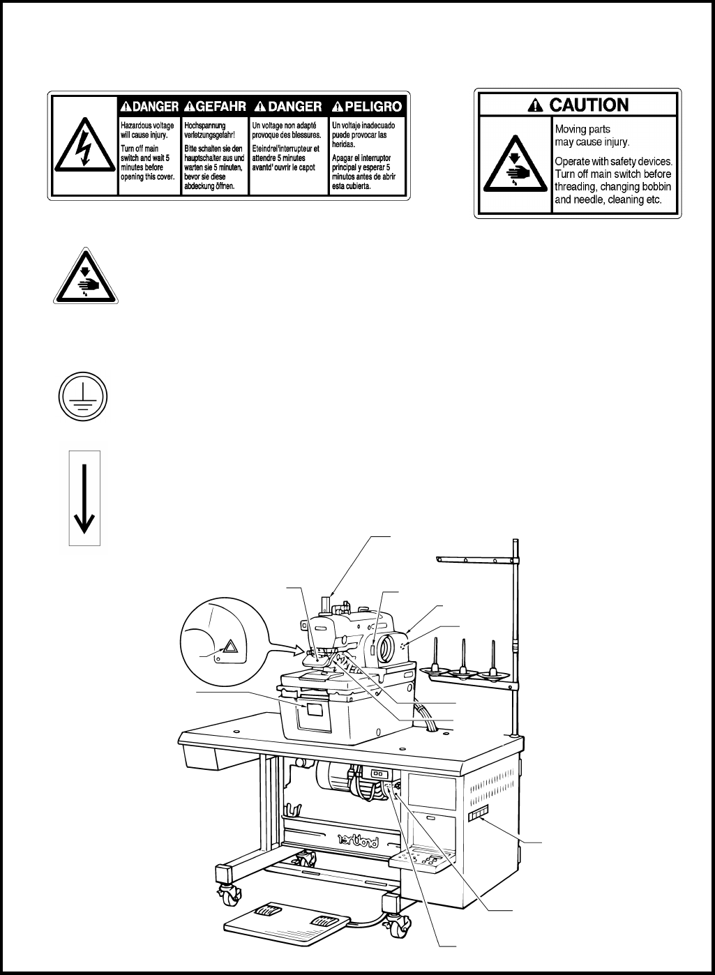
3. Warning labels
The following warning labels appear on the sewing machine.
Please follow the instructions on the labels at all times when using the machine. If the labels have been removed
or are difficult to read, please contact your nearest Brother dealer.
Safety devices
Eye guard
Finger guard
Needle bar guard
Belt cover, etc.
3Do not touch the knife or press any objects
against the machine while sewing, as this
may result in personal injury or damage to
the machine.
4
Be sure to connect the ground. If the ground connection is not secure, you run a high risk o
f
receiving a serious electric shock, and problems with correct operation may also occur.
5Direction of operation
Belt cover
Needle bar guard
Eye guard 5
2
Finger
guard
1
2010Q
12
4 (Rear)
Belt cover
Winding prevention bar
3
3

CONTENTS
1. NAMES OF EACH PART ............................1
2. SPECIFICATIONS ..........................................2
2-1. Specifications .......................................................2
3. INSTALLATION.................................................3
3-1. Table processing diagram .................................3
3-2. Installing the motor .............................................4
3-3. Installing the machine head ...............................4
3-4. Installing the oil container ...................................5
3-5. Installing the spool stand ....................................6
3-6. Tightening the V-belt ..........................................6
3-7. Installing the control box ....................................7
3-8.
Installing the air unit and the valve assembly
.......7
3-9.
Connecting the ground wires and the wirings
.......8
3-10. Connecting the air tubes ....................................9
3-11. Installing the air hoses ......................................10
3-12. Connecting the power cord ..............................11
4. LUBRICATION..................................................12
4-1. Adding oil ..........................................................12
4-2. Lubrication ........................................................12
5. CORRECT USE ..............................................14
5-1. Initializing settings .............................................14
5-2.
Changing the lower thread and gimp trimming
........14
5-3.
Checking the direction of machine operation
.......15
5-4. Installing the needle ..........................................16
5-5. Threading the upper thread ..............................16
5-6. Threading the lower thread...............................17
5-7. Threading the gimp ..........................................18
5-8. Setting the material ...........................................18
6. USING THE OPERATION PANEL
AND FRONT PANEL ...................................19
6-1. Panel button and switch names ......................19
6-2. Selecting a program number ...........................20
6-3. Changing the mode ..........................................20
6-4. Changing the cutting timing .............................20
6-5. Setting a program .............................................21
A. Setting the sewing speed ...............................22
B. Setting the shape of the eyelet.......................22
C. Setting the buttonhole length .........................22
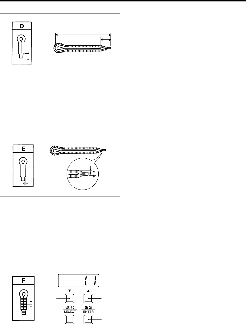
D. Setting the tacking length ...............................23
E. Setting the offset .............................................23
F. Setting the stitch pitch.....................................23
G. Setting the number of eyelet stitches.............24
H. Setting the cutting space ................................24
I. Setting the knife position compensation ........24
P1. Setting X correction .......................................25
P2. Setting Y correction .......................................25
P3. Setting θ1 correction.......................................25
P4. Setting θ2 correction.......................................26
6-6. Using the memory switch .................................27
6-7. List of error codes .............................................29
7. SEWING .............................................................. 30
7-1. Using the EMERGENCY STOP switch .......... 30
7-2. Sewing .............................................................. 31
7-3. Adjusting the thread tension ............................ 32
7-4. Needle and knife position ................................ 33
7-5. Using the production counter .......................... 35
7-6. Using a cycle program ..................................... 36
7-7.
Setting the feed bracket to the front position
...... 37
7-8.
Switching between single-pedal and dual-pedal
operation (Switching the foot controller)
............. 37
7-9. Using feed mode ............................................. 38
7-10. Using manual mode ........................................ 39
7-11. Changing the cycle program counter ............. 40
7-12.
Setting the number of home position cycles
...... 40
7-13. Returning to the home position ....................... 41
8.
CLEANING AND MAINTENANCE
......42
8-1. Cleaning ........................................................... 42
8-2. Draining the oil ................................................. 42
8-3. Checking the air filter ....................................... 42
9. STANDARD ADJUSTMENTS ............... 43
9-1.
Adjusting the height of the spreader and looper
....... 43
9-2. Adjusting the needle and looper timing ........... 44
9-3. Adjusting the loop stroke .................................. 45
9-4. Adjusting the height of the needle bar ............. 46
9-5. Adjusting the clearance between the
looper and needle............................................. 46
9-6. Adjusting the needle guard .............................. 47
9-7.
Adjusting the spreader mounting positions
......... 47
9-8. Adjusting the spreader timing .......................... 48
9-9. Adjusting the needle racking width
(stitch width) ...................................................... 48
9-10. Changing the knife cutting length
(Replacing the cutting block)............................ 49
9-11. Adjusting the contact between the knife
and the cutting block ........................................ 50
9-12. Replacing the knife .......................................... 51
9-13. Adjusting the cutting pressure ......................... 51
9-14. Adjusting the cloth opening amount ............... 52
9-15.
Adjusting the trimming of the upper thread
...... 53
9-16. Adjusting the trimming of the lower thread
and gimp .......................................................... 53
9-17.
Adjusting the gimp length after trimming (-02)
... 54
9-18. Lower thread presser (-02) .............................. 55
9-19. Sub presser (-02) ............................................. 55
10.
SUMMARY OF DIP SWITCHES
......... 56
10-1. Front panel DIP switches .............................. 56
10-2. Circuit board DIP switches ............................ 57
11. TROUBLESHOOTING ............................ 58

1. NAMES OF EACH PART
RH-9800 1
1. NAMES OF EACH PART
(1) Front cover (2) EMERGENCY STOP switch (3) Upper shaft pulley (4) Control panel
(5) Control box (6) Front panel (7) Start switch (8) Cloth presser switch
(9) Foot controller (10) Power switch (11) Motor
(8)
(10)
(9)
(1)
(2)
(4)
(7)
(3)
(5)
1096
Q
(11)
(6)
2. SPECIFICATIONS
RH-9800
2
2. SPECIFICATIONS
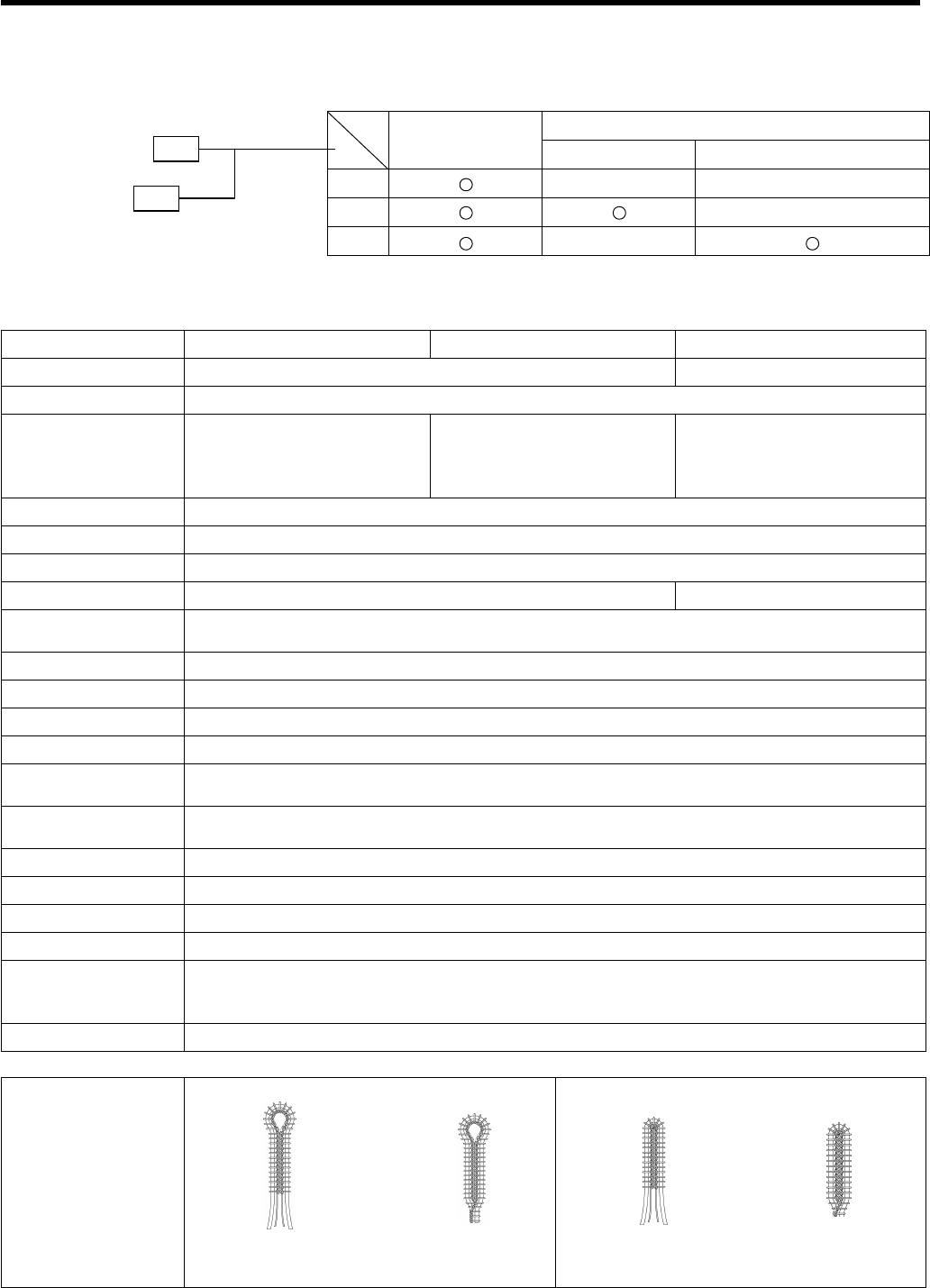
2-1. Specifications
Lower thread trimmer
Upper thread
trimmer Long type Short type
-00 - -
-01 -
-02 - *
Specification -00 -01 -02
Application Men's clothes and ladies' clothes Jeans and work clothes
Sewing speed 1,000 - 2,000 rpm (100 rpm steps)
Button hole length 10 – 50 mm 10 – 38 mm
L1 14 – 18 mm L5 28 – 32 mm
L2 18 – 22 mm L6 32 – 36 mm
L3 22 – 26 mm L7 36 – 40 mm
L4 26 – 30 mm
Stitch pitch 0.5 - 2.0 mm (0.1 mm steps)
Stitch width 1.5 - 3.2 mm
Tacking length 3 – 43 mm (1 mm steps) or none
Cloth presser height 12 mm 16 mm
Stitch shape
changing Selected by a program
Cut timing selection Selected by a switch
Starting method Dual switch (cloth presser switch and start switch) or single switch
Feed method Intermittent feed by three pulse motors (X, Y, θ)
Needle DO x 558 Nm 80 – Nm 120 (Schmetz)
Safety equipment Built-in emergency stop function and automatic stopping device which stops the machine when
the safety circuit is activated
Air pressure Main regulator: 0.5 MPa
Knife pressure regulator: 0.3 MPa
Air consumption 43.2 l/min. (8 cycles/min.)
Noise level 81 dB at max. speed of 2,000 rpm, measured according to ISO 10821
Dimensions 1,200 mm (W) x 590 mm (D) x 1,120 mm (H)
Work table legs T-shaped height-adjustable type
Power supply Single-phase 110, 200, 220, 230, 240 V
3-phase 220, 380, 415 V
Maximum electric power consumption: 1 kVA
Weight 175 kg
Eyelet buttonhole Straight buttonhole
Sewing shape
Eyelet buttonhole Eyelet buttonhole with
taper Straight buttonhole Straight buttonhole
with taper
* -02 is further divided into L1 - L7 specifications in accordance with the stitch
length. Please be sure to specify the stitch length when ordering.
DH4-B980-
RH-9800-
0793Q 0794Q 0795Q 0796Q
3.INSTALLATION
RH-9800 3
3. INSTALLATION
CAUTION
Machine installation should only be carried out by
a qualified technician.
Contact your Brother dealer or a qualified electrician
for any electrical work that may need to be done.
The sewing machine weighs more than 87 kg. The
installation should be carried out by two or more
people.
Do not connect the power cord until installation is
complete, otherwise the machine may operate if
the start switch is pressed by mistake, which could
result in injury.
All cords should be secured at least 25 mm away
from any moving parts. Furthermore, do not
excessively bend the cords or secure them too
firmly staples, otherwise there is the danger that
fire or electric shocks could occur.
Be sure to connect the ground. If the ground
connection is not secure, you run a high risk of
receiving a serious electric shock, and problems
with correct operation may also occur.
Install the belt covers to the machine head and
motor.
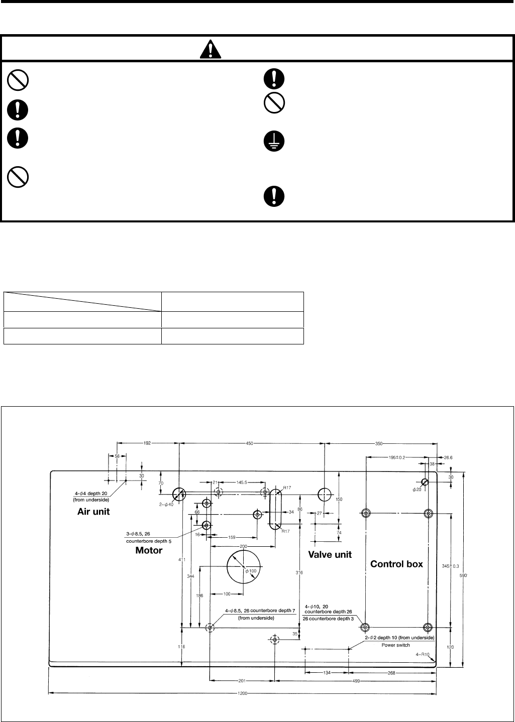
3-1. Table processing diagram
Use the special table indicated below.
Thread trimmer Product code
Upper thread trimmer 127-980-000-01
Upper and lower thread trimmer 127-980-001-01
If using a commercially-available table, process it as shown in the illustration below.
Note: The thickness of the table should be at least 50 mm, and it should b e strong enough to bear the weight and
vibration of the sewing machine.
2011Q
3. INSTALLATION
RH-9800
4
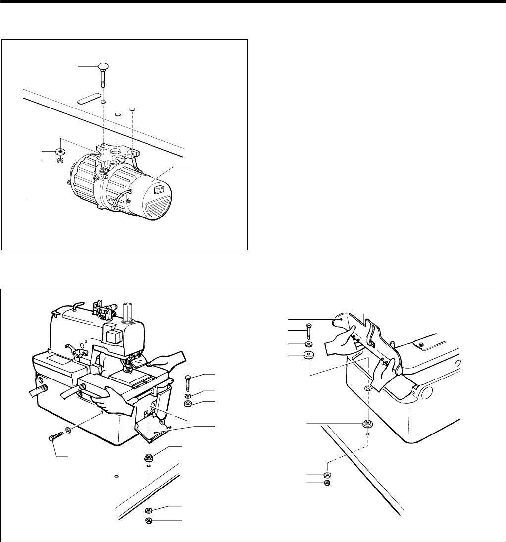
3-2. Installing the motor
1. Insert the three bolts (1) into the work table.
2. Turn the work table upside down to make it easier to
install the motor (2).
3. Align the motor (2) with the bolts (1), and then install
the motor (2) to the underside of the work table with
the three washers (3) and the three nuts (4).
Note: Do not use the cushion rubber. If you use it, V
belt tension cannot be adjusted.
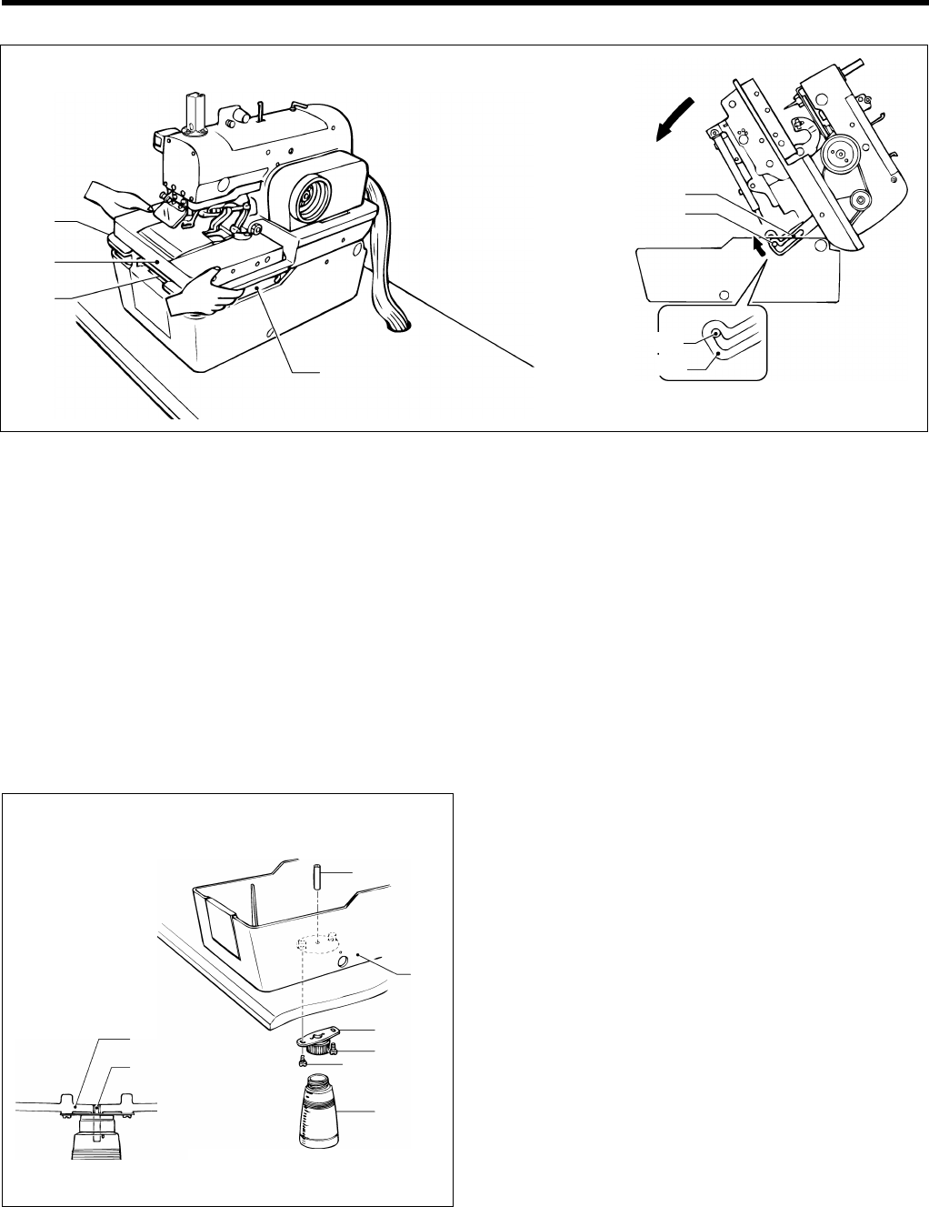
3-3. Installing the machine head
1. Insert the accessory bed stand cushions A (1) into the bed stand, and then place the machine head on top of the work
table.
Note: When placing the machine head on top of the work table, have two or more people there to hold the handles A
and B and the rear of the head C.
2. Open the front cover (2), and then use the bed stand mounting bolt (3), washer (4), cushioning rubber (5), bed stand
cushion A (1), large washer (6) and nut (7) to attach the front right corner of the bed stand to the work table.
3. Open the rear cover (8), and then attach the bed stand to the work table in two places inside the stand in the same
way as in step 2. above.
4. Remove the fixing bolt (9) and the washer.
Note: The fixing bolt (9) and washer should be kept, as they will be needed again if the machine head is moved.
5. Raise the machine head, and then attach the front left corner of the bed stand to the work table in the same way as in
the steps above.
Note: Make sure that steps 2. to 4. above have been completed before raising the machine head.
(2)
(4)
(3)
(1)
1098Q
(3)
(4)
(5)
(2)
(9)
(1)
(7)
(1)
(3)
(4)
(5)
0808Q
(6)
(8)
(6)
(7)
1099Q
3.INSTALLATION
RH-9800 5
Raising the machine head
1. While holding the handles of the machine head (1) with both hands, gently raise the machine head.
Note: Be sure to turn the power supply off before raising the machine head.
2. If you wish to keep the machine head in the raised position, insert the head support lever (2) securely into the hinge
lever support shaft (3).
Note: Always check that the head support lever (2) and the hinge lever support shaft (3) are meshed.
Lowering the machine head
Pull the machine head down toward you gently, remove the head support lever (2) from the hinge lever support shaft
(3), and then gently lower the machine head.
Note: Do not hold the machine head by the feed bracket (4) or X feed shaft A (5) when it is being raised and
lowered.
3-4. Installing the oil container
1. Install the oil draining cap support (2) to the base of
the bed stand (1) with the two screws (3).
2. Screw the oil container (4) into the oil draining cap
support (2).
3. Push the oil draining spring pin (5) into the bed stand
(1) until the pin is flush with the surface of the stand.
4. Lower the machine head. (Refer to "Lowering the
machine head" above.)
When machine head is raised 0810Q0809Q
When machine
head is lowered
(
2
)
(
3
)
(1)
(5)
0811Q
0812Q
(5)
(1)
(5)
(1)
(2)
(3)
(3)
(4)
(4)
(1)
(2)
(3)
3. INSTALLATION
RH-9800
6
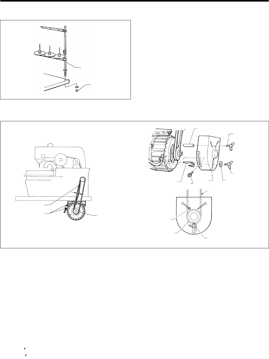
3-5. Installing the spool stand
1. To assemble the spool stand (1), follow the instructions in
the manual that came with the spool stand (1).
2. Secure the spool stand (1) to the rear right corner of
the work table with the washer and nut (2).
3-6. Tightening the V-belt
1. Open the rear cover.
2. Pass the V-belt (1) through the base of the bed stand and through the hole in the work table.
3. Loosen the two screws (2) and then remove the motor pulley cover (3).
4. Place the V-belt (1) onto the motor pulley (4).
5. Check that there is approximately 10 mm of deflection in the V-belt (1) when it is pushed in the middle with a load of 0.1 N.
If the tightness needs adjusting, loosen the two nuts (5) and move the motor up or down.
6. Install the belt casting prevention bracket (8) to the pulley cover (3) with the wing bolt (6) and washer (7).
Align the center of the washer (7) with the gradation (7) 0 shown on the outside of the pulley at this time.
7. Provisionally tighten the winding prevention bar (9) to the pulley cover (3) with the wing bolt (10).
8. Install the pulley cover (3) and tighten it with the two screws (2).
Note: Check that the V-belt is not touching the belt casting prevention bracket (8).
9. Align the winding prevention bar (9) with the point in between the V-belt and the motor pulley, and then secure it by
tightening the wing bolt (10).
Note: Check that the winding prevention bar (9) does not touching the V-belt or the motor pulley.
After a long period of use, the V-belt will become run in and will loosen around the motor pulley. When this
happens, turn off the power and adjust by the procedure given in step 5. above.
0815Q
(1)
(2)
1100Q 1101Q
1198Q
(4)
(1)
(5)
(9)
(1)
(7)
(2)
(8) (3) (7)
(6)
(9)
(1) (10)
Motor pulley
Approx.
10 mm
0.1N
3.INSTALLATION
RH-9800 7
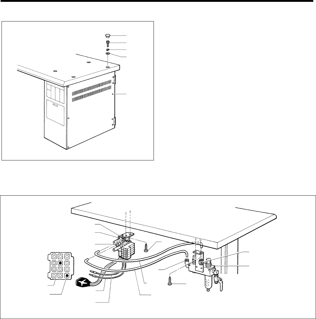
3-7. Installing the control box
1. Align the four bolt holes in the control box (1) with the
four holes in the work table.
2. Install the control box (1) with the four bolts (2), spring
washers (3) and flat washers (4)
3. Push the four caps (5) in over the top of the bolts (2).
3-8. Installing the air unit and the valve assembly
Refer to the work table processing diagram on page 3 for the installation position.
1. Install the air unit (1) to the underside of the work table with the two screws (2).
2. Install the valve assembly (3) with the two screws (4).
3. Connect air hose No. 15 to the intermediate joint (5) of the air unit (1) and to the joint (6) of the valve assembly (3), and
connect air hose No. 16 to joints (7) and (8).
Connecting the knife valve cables
Connect the two black knife valve cables to terminal No.4 and No.6 of the 12-pin connector of the air harness.
1103Q
12-pin connector
No.6 (black)
No.4 (black) Black cable
12-pin connector
Black cable
(1)
(5)
(2)
(7)
(4)
(8)
(3)
(6)
No. 15
No. 16
1102Q
(5)
(2)
(3)
(4)
(1)
3. INSTALLATION
RH-9800
8
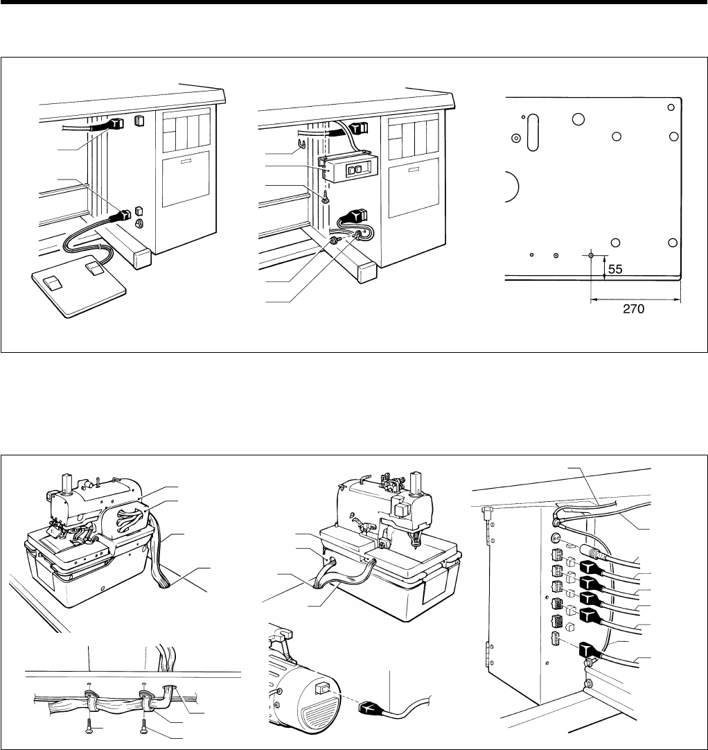
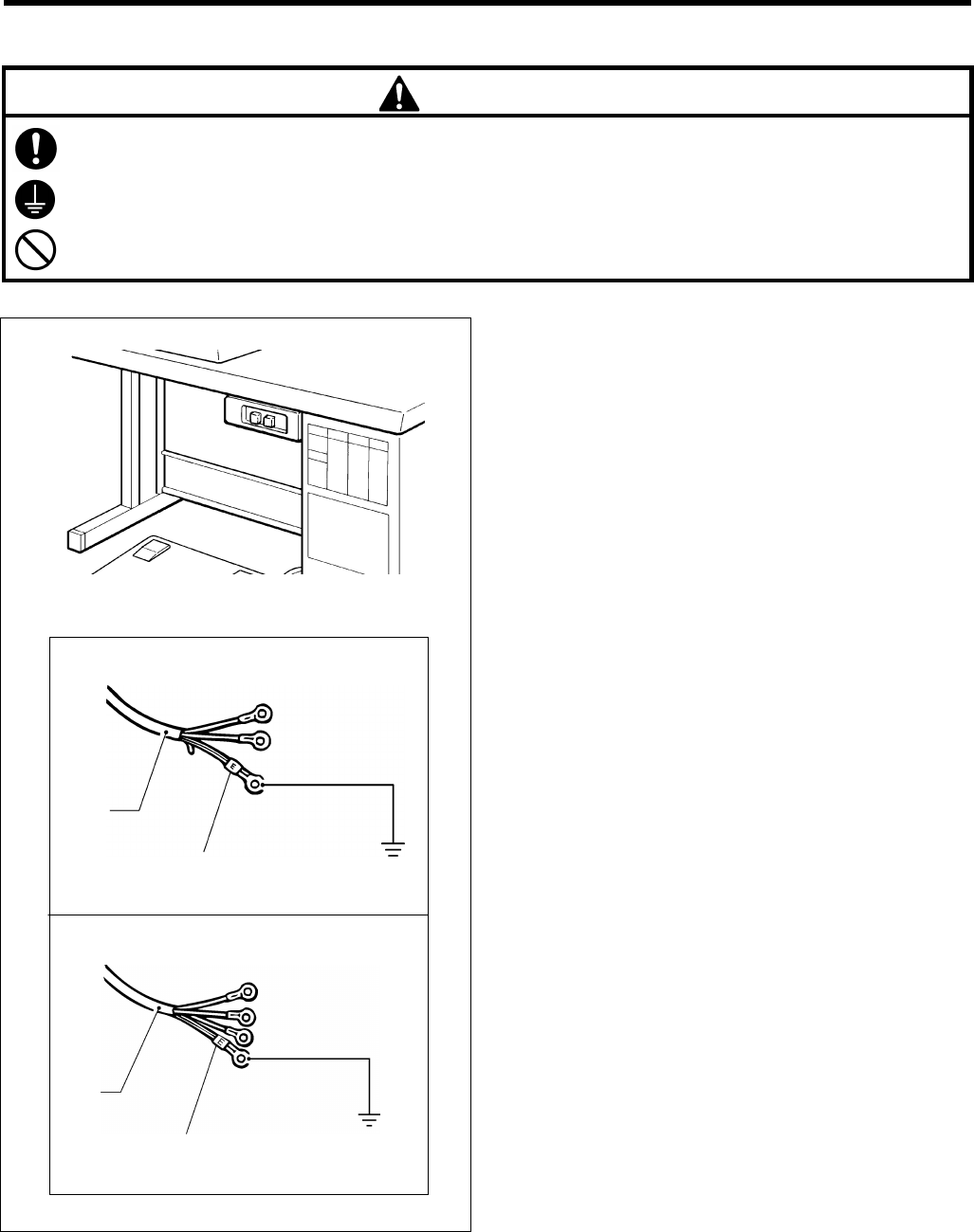
3-9. Connecting the ground wires and the wirings
1. Connect the foot controller cable (1) and the motor cable (2) to the control box.
2. Install the power switch (3) to the underside of the work table with the two screws (4).
3. Clamp the foot controller cable (1) with the two cable clips (5) and then secure the cable clips (5) with the screws (6).
4. Install the motor cable (2) and the power switch cable to the underside of the work table with the staple (7).
5. Pass the cable and air tube which are coming out of the feed bracket (8) and the left side of the bed stand (9) through
the cable hole (10) in the work table.
6. Pass the cable and air tube which are coming out of the belt cover (11) and the machine head (12) through the cable
hole (13) in the work table.
7. Insert each of the connectors into the connectors on the control box. (Refer to the illustration above.)
8. Pass the cables and air hoses through the two cable holders (14), and then secure the cable holders (14) to the
underside of the work table with the two screws (15).
9. The ground wires (16), (17) should always be connected to the control box.
10.Connect the accessory ground wire (18) to the ground terminal of the control box and to the table leg installation bolt.
Note: If the ground wire is not connected, mis-operation due to discharges of static electricity may occur.
11. Connect the power switch connector (19) to the motor.
1106Q
(2)
(1)
(7)
(3)
(4)
Needle
position sensor
1110Q 1111Q1108Q
1107Q 1109Q
(9)
(8)
(12)
(11)
(16)
(13) (10)
(17)
(19)
(10)
(14)
(15)
(15)
(16)
(17)
(18) 4P
12P
6P
6P
6P
White
Blue
Black
White
White
White
(5)
(6)
Power switch installation position
1104Q 1105Q
3.INSTALLATION
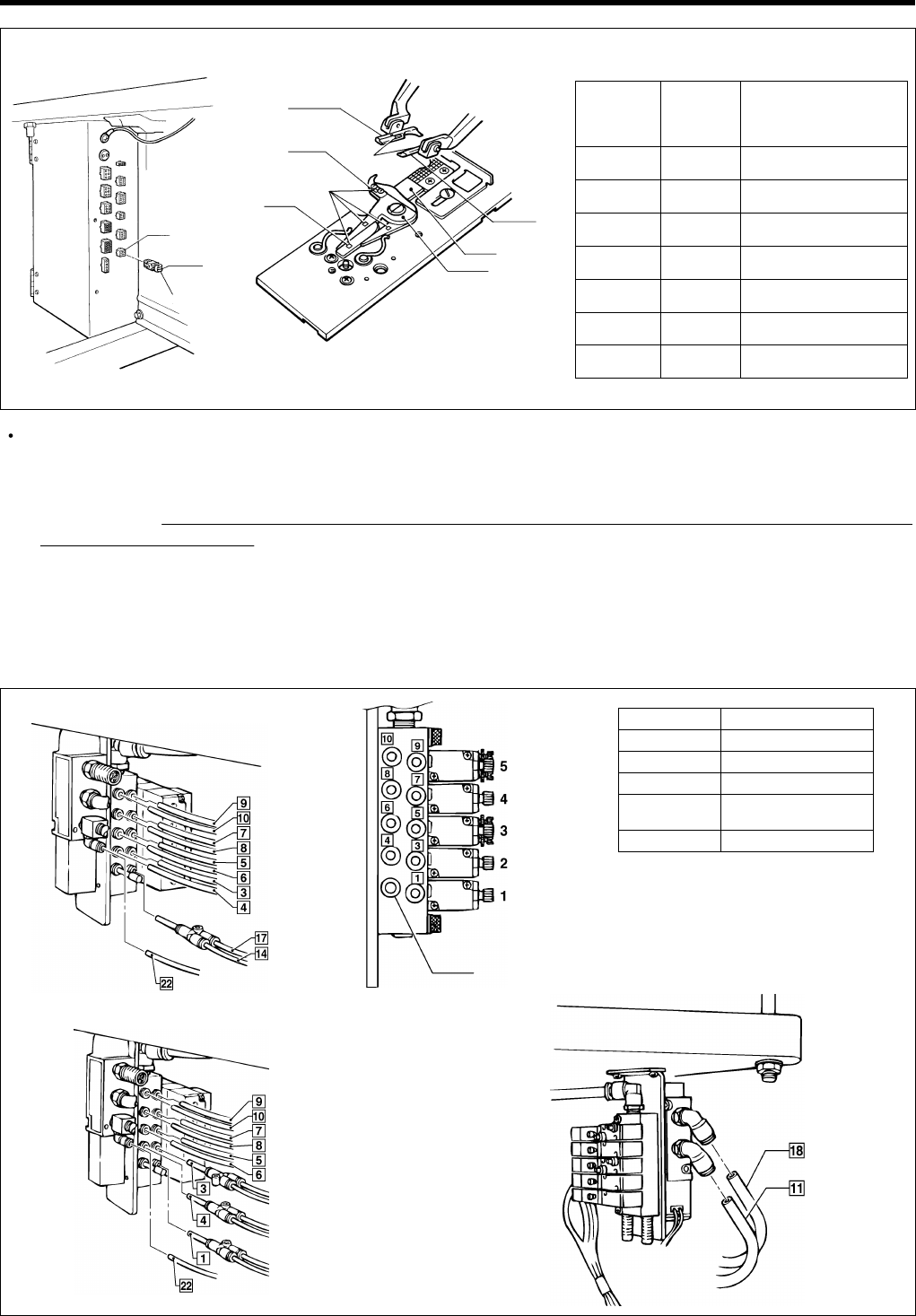
RH-9800 9
Insert the harness (L1 - L7) (1) to connector No. 10 (9-pin).
* When connecting the harness (1), check that its label number is the same as the numbers on the right movable
knife (2), left movable knife (3), thread handler (4), right cloth presser (5), left cloth presser (6) and movable knife
driving cam (7). (If a connector with a different label number is inserted, the machine could be damaged or thread
trimming errors could result.)
* There is 10 mm of difference in the knife installation positions between L1 - L4 and L5 - L7.
3-10. Connecting the air tubes
Connect the air tubes to the joints of the solenoid valve assembly, using the illustration below as a reference.
Numbers are marked on each of the air hoses which come out of the sewing machine.
Specification Label No. of
harness
Right/left cloth presser No.
Right/left movable knife No.
Thread handler No.
L1 11
L2 22
L3 33
L4 44
L5 5 5
L6 6 6
L7 7 7
< -02 >
No.10
Label No.
(1)
1112Q 1113Q
No.
No.
(5)
(2)
(3)
(7)
(4)
(6)
Label No. Solenoid valve
5Upper thread trimming
4Upper thread tightening
3
Lower thread tr
i
mm
i
ng *1
2Cloth spreading
(Sub presser *2)
1Cloth presser
*1 If the lower thread trimmer is not
installed, solenoid valve [3] is not
used.
*2 The sub presser can only be used
for machines with -02 specification.
< -00,-01 >
< -02 >
0826Q
0827Q
Plug 4
0828Q 0829Q
3. INSTALLATION
RH-9800
10
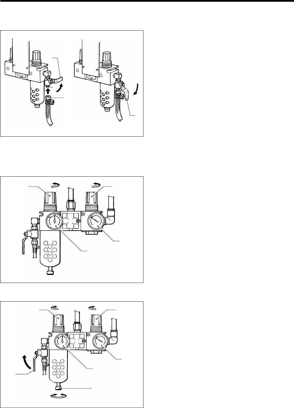
3-11. Installing the air hoses
Connect the air hose from the compressor to the air unit underneath the work table.
1. Turn the nut (1) at the end of the air hose, and then
connect the hose to the valve (2).
2. Open the air cock (3) on the compressor.
Check that there is no air leaking from the valve
connection.
3. Open the cock (3) by turning it in the direction of the
arrow.
The meter needle will move clockwise.
4. Adjust the air pressure by following the procedure on
the next page.
Adjusting the air pressure
Set the air pressure for the knife pressure adjustment regulator (3) to the lowest pressure at which the knife can still cut
the material. Set the standard air pressure for the main regulator (1) to 0.5 MPa.
To increase the air pressure 1. Gently lift the knob (2) of the main regulator (1) and
turn it in the direction of the arrow in the illustration.
The pressure will increase when the knob (2) is turned
clockwise.
2. Gently lift the knob (4) of the knife pressure adjustment
regulator (3) and turn it in the direction of the arrow in
the illustration.
The pressure will increase when the knob (4) is turned
clockwise.
* The pressure for the knife pressure adjustment
regulator (3) is adjusted to 0.3 MPa. Be careful not
to increase this pressure needlessly, otherwise
poor cutting performance or damage to the knife
may result.
To decrease the air pressure 1. Close the cock (5). (The needle will remain at the high
pressure position.)
2. Turn the knob screw (6) in the direction of the arrow in
the illustration to loosen it. Make sure that you turn it in
the correct direction.
The air will escape from the reservoir and the needle
will drop.
3. Tighten the knob screw (6).
4. To reduce the air pressure, gently lift knob (2) or knob
(4) and turn it counterclockwise.
5. Open the cock (5). Air will enter the reservoir and the
needle will move
0834Q 0835Q
Closed
Open
(1)
(3)
(3)
(2)
(0.3 MPa)
(0.5 MPa)
(3)
(1)
(2) (4)
0836Q
0837Q
(0.5 MPa) (0.3 MPa)
(3)
(1)
(4)
(2)
(5)
(6)
To tighten
To loosen
To close
3.INSTALLATION
RH-9800 11
3-12. Connecting the power cord
CAUTION
Contact your Brother dealer or a qualified electrician for any electrical work that may need to be done.
Be sure to connect the ground. If the ground connection is not secure, you run a high risk of receiving a serious
electric shock, and problems with correct operation may also occur.
Do not connect the power cord until installation is complete, otherwise the machine may operate if the start
switch is pressed by mistake, which could result in injury.
1. Attach an appropriate plug to the power cord (1). (The
green and yellow wire is the ground wire.)
2. Insert the plug into properly-grounded AC power
supply.
Note: Do not use extension cords, otherwise
machine operation problems may result.
0840Q
0839Q
(1)
Single phase
Three phase
Green and yellow wire
(ground wire)
(1)
Green and yellow wire
(ground wire)
1114Q
4. LUBRICATION
RH-9800
12
4. LUBRICATION
CAUTION
Turn off the power switch before starting lubricating, otherwise the machine may operate if the start switch is
pressed by mistake, which could result in injury.
Be sure to wear protective goggles and gloves when handling the lubricating oil and grease, so that they do not
get into your eyes or onto your skin, otherwise inflammation can result.
Furthermore, do not drink the oil or eat the grease under any circumstances, as they can cause vomiting and
diarrhoea.
Keep the oil out of the reach of children.
Use only specified Brother oil (Nisseki Mitsubishi Sewing Lube 10 N; VG10) for the machine oil.
4-1. Adding oil
Check the oil level by looking at the sight glass. If the oil level is low, replenish the oil supply.
Filling the arm oil tank Filling the bed base oil tank
4-2. Lubrication
Oil these parts once a day.
Oil the moving parts of the needle bar, looper and spreader mechanisms and also the cam groove, roller, the felt at the
base of the wick and the wick before using the sewing machine for the first time, and also after long periods of non-use.
When oiling, some oil will get onto the thread. Carry out a test sewing to ensure that your material does not get stained
with oil.
Oiling the needle bar and cam
Add 2-3 drops of oil in the places indicated by the arrows.
(1)
(2)
0859Q 0860Q
1. Pour approximately 10 cc of machine oil into the arm oil
tank (1) (until it is about four-fifths full).
1. Raise the machine head.
2. Pour approximately 20 cc of machine oil into the bed
base oil tank (2) (until it is about four-fifths full).
3. Lower the machine head.
0861Q
4.LUBRICATION
RH-9800 13
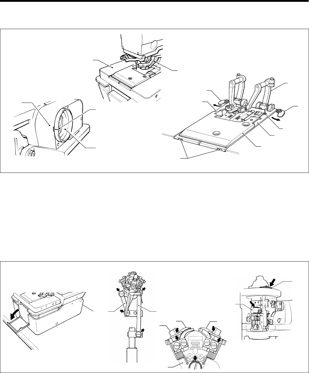
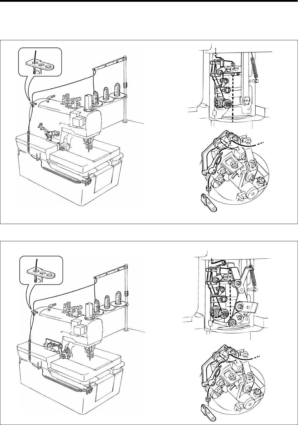
Oiling the looper, spreader and race stand
<Removing the cloth presser plates>
1. Turn the upper shaft pulley (1) toward you until the mark on the pulley (A) is aligned with the notch in the pulley cover (2).
2. Move the feed bracket (3) toward you.
3. Turn the left and right plate pressers (4) in the directions indicated by the arrows.
4. Lift up the clamp lever (6) and the notched section (7) of the right cloth presser plate (5), remove the right cloth presser
plate (5) from the pin (8), and then pull the right cloth presser plate (5) toward you to remove it.
Note: If the lower thread trimmer has been installed, move cloth presser plate U (9) to a position where it can be
removed without its touching the needle.
Raise cloth presser plate U (9), pass the needle through the hole, and then remove cloth presser plate U (9)
from the pin (8).
5. Remove the left cloth presser plate (10) in the same way as the right cloth presser plate (5) was removed.
6. Open the front cover.
7. Turn the race stand and add a few drops of oil to the spreader cam (11), and to the supports for the looper link (12)
and spreader link (13).
8. Add a few drops of oil to the shafts of the right spreader (14), left spreader (15) and LS-holder bracket (16).
9. Fill the felt tank (17) on the race stand with oil also.
10.Add 5 - 6 drops of oil to the felt (18) which is attached to the sliding surfaces of the race stand and the bed.
11. Close the front cover.
12.Install the cloth presser plates by carrying out the steps 5., 4. and 3. in that order.
(3)
(6)
(2)
(1)
(A)
(4)
(10)
(8)
(6)
(4)
(5)
(9)
(7)
1116Q
0862Q 1117Q
(13)
(18)
(12)
(14)
(15)
(11)
(16)
(17)
0868Q
0866Q1118Q 1119Q
5. CORRECT USE
RH-9800
14
5. CORRECT USE
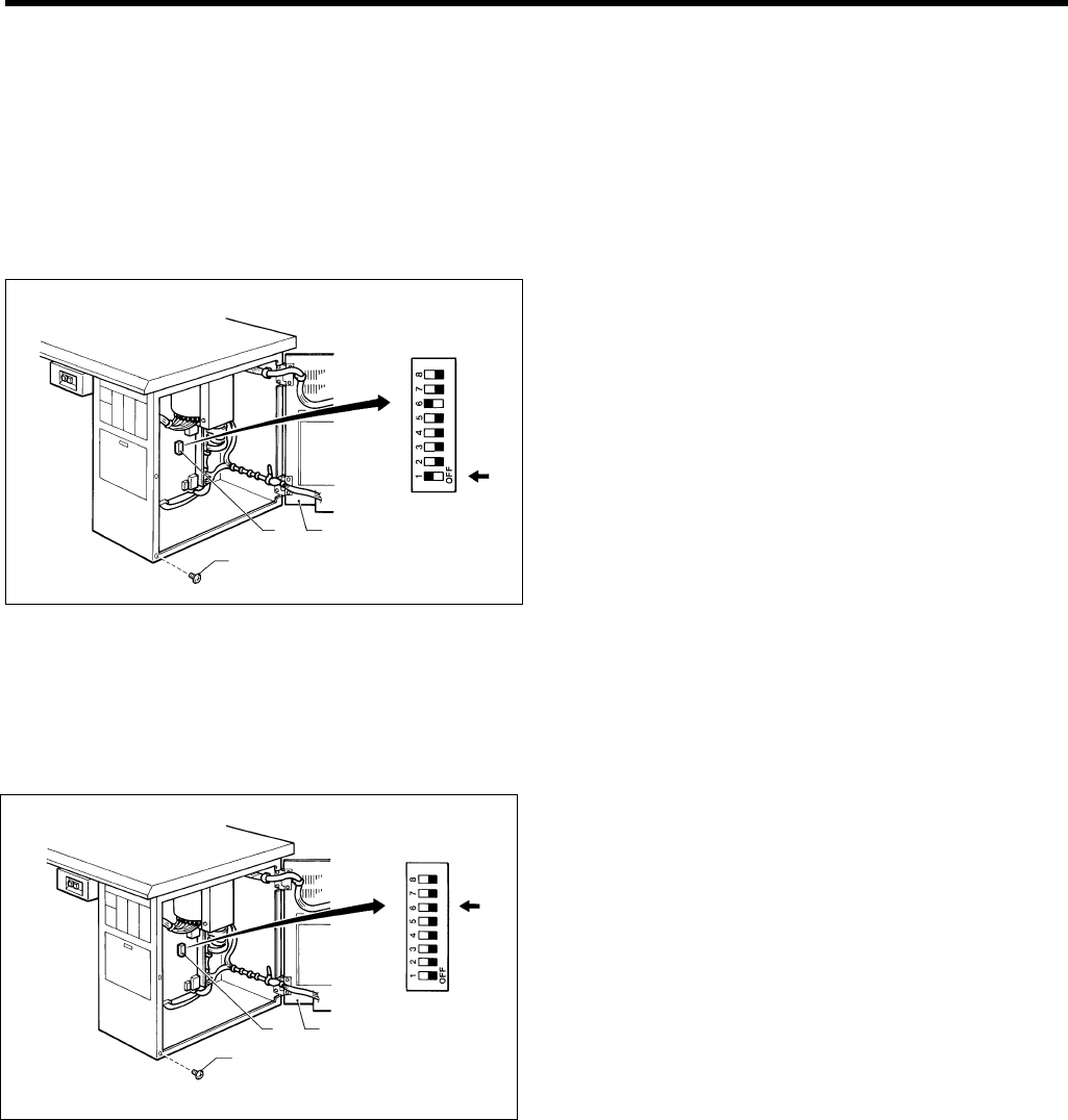
5-1. Initializing settings
The following procedure should be carried out before the sewing machine is used for the first time, and also after long
periods of non-use.
If "E-59" appears on the front panel display when the power is turned on, be sure to follow this procedure to initialize all
settings. ("E-59" will appear after a PROM has been replaced or after long periods of non-use. For details on the "E-59"
message display, refer to page 27.)
1. Turn off the power.
2. Remove the five screws (1).
3. Open the rear plate (2) of the control box.
4. Set DIP switch No. 1 (3) on the circuit board to ON.
5. Turn the power back on again.
Note: A buzzer will sound while the data is being
initialized.
6. Turn off the power.
7. Set DIP switch No. 1 (3) on the circuit board to OFF.
8. Close the rear plate (2) and tighten the five screws (1).
5-2. Changing the lower thread and gimp trimming
The sewing machine is set to lower thread and gimp trimming when it is shipped from the factory. (DIP switch No. 6 (3)
is set to ON.)
Carry out the following procedure only if you wish to activate upper thread trimming.
1. Turn off the power.
2. Remove the five screws (1).
3. Open the rear plate (2) of the control box.
4. Set DIP switch No. 6 (3) on the circuit board to OFF.
Note: Do not activate lower thread trimming if using
a 39-mm cutter.
Do not set DIP switch No. 6 (3) on the circuit
board to ON.
5. Close the rear plate (2) and tighten the five screws (1).
(2)
(1)
(3) (2)
1120Q
(2)
(3)
(1)
1121Q
5. CORRECT USE
RH-9800 15
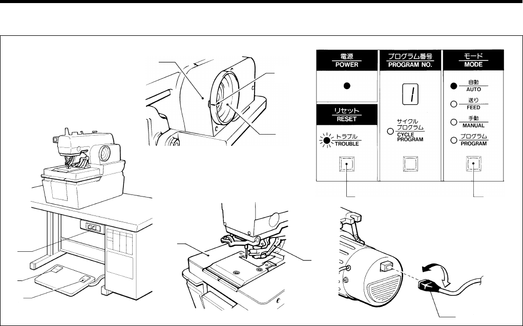
5-3. Checking the direction of machine operation
1. Turn the upper shaft pulley (1) toward you until the mark (A) on the pulley (1) is aligned with the notch in the cover (2).
2. Press the power switch (3) to turn on the power.
The power indicator will illuminate and the TROUBLE indicator will flash.
3. Press the RESET button (4).
The TROUBLE indicator will switch off and the feed bracket (5) will move to the cloth setting position.
4. Press the MODE button (6) to switch to automatic mode.
The AUTO mode indicator will illuminate.
5. Depress the cloth presser switch (7).
The cloth presser (8) will be lowered.
6. Depress the start switch (9).
The machine will sew one buttonhole and will then stop.
* If the buzzer makes a beeping sound and "E-89" appears on the front panel display, the direction of operation of the
upper shaft is reversed.
Press the power switch (3) to turn the power off, and then switch over the top and bottom motor connectors (10).
7. The direction of machine operation will now be correct.
(2)
(1)
(5)
(3)
(7)
(9)
(4)
(10)
(6)
(A)
(8)
0862Q 1124Q
1123Q1116Q
1122Q

5. CORRECT USE
RH-9800
16
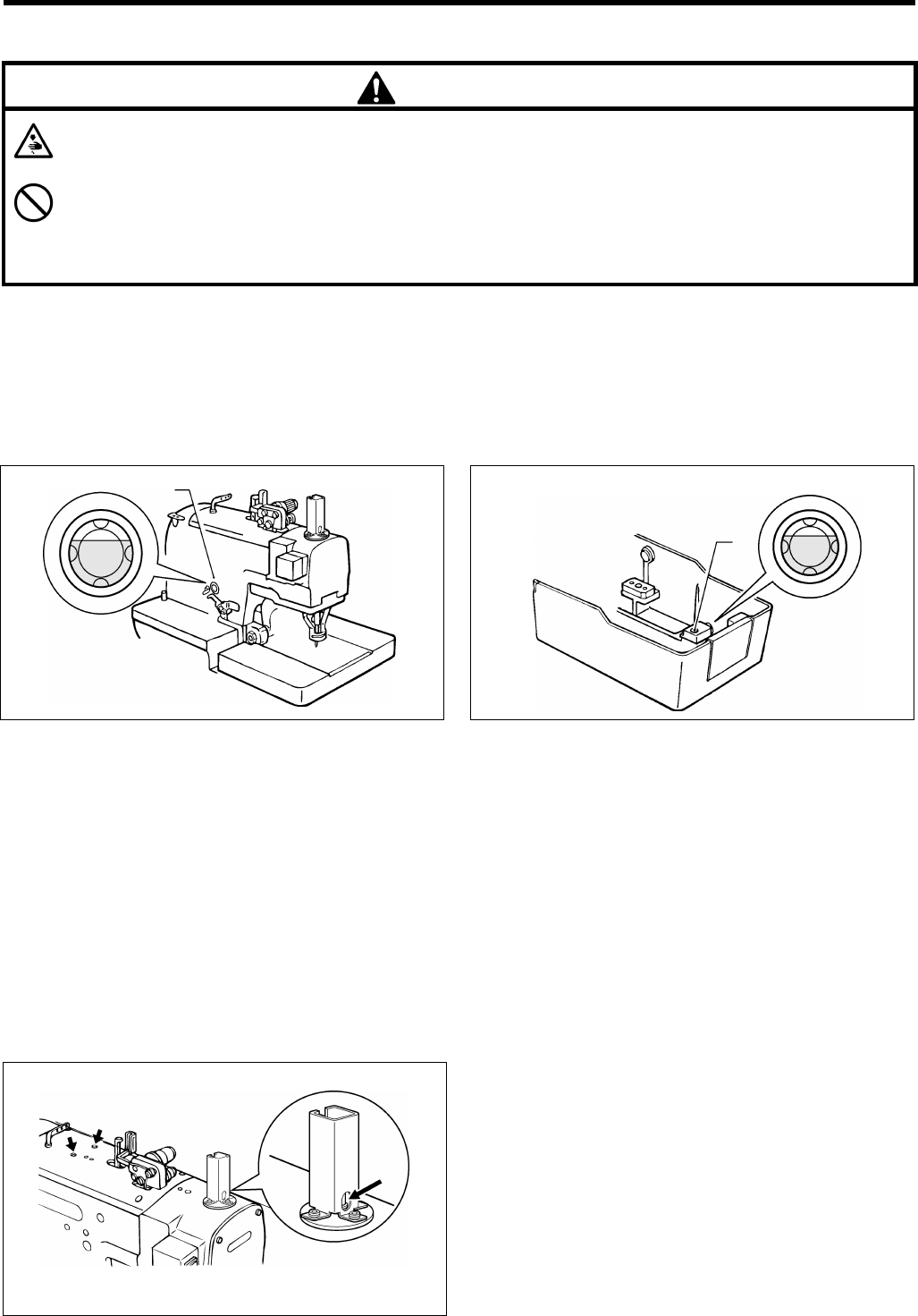
5-4. Installing the needle
CAUTION
Turn off the power switch before installing the needle, otherwise the machine may operate if the start switch is
pressed by mistake, which could result in injury.
Use only Schmetz D0 x 558 Nm80 – Nm120 needles.
1. Raise the finger guard (1).
2. Loosen the screw (2), and then remove the needle (3).
3. Insert the new needle (3) as far as it will go so that the
groove is facing toward you.
4. Securely tighten the screw (2).
5. Remove the cloth presser plates. (Refer to page 13.)
Note: After removing the cloth presser plates, check
that the index mark (4)on the machine head is
aligned with the index mark (5) on the race
stand before inserting the needle (3) (when
the race stand is turned fully to the right).
6. Lower the finger guard (1).
5-5. Threading the upper thread
CAUTION
Turn off the power switch before threading the thread, otherwise the machine may operate if the start switch is
pressed by mistake, which could result in injury.
Thread the upper thread as shown in the illustration below.
* Use the accessory needle threader (1).
(1)
(2)
(3)
(5)
(4)
0872Q
0873Q
0871Q
(1)
0875Q
0878Q0877Q1125Q
5. CORRECT USE
RH-9800 17
5-6. Threading the lower thread
Remove the cloth presser plates (refer to page 13), and then thread the lower thread as shown in the illustration below.
For upper thread trimming specifications (-00)
For upper and lower thread trimming specifications (-01, -02)
0879Q 0881Q
0880Q
0883Q
0882Q 0881Q
5. CORRECT USE
RH-9800
18
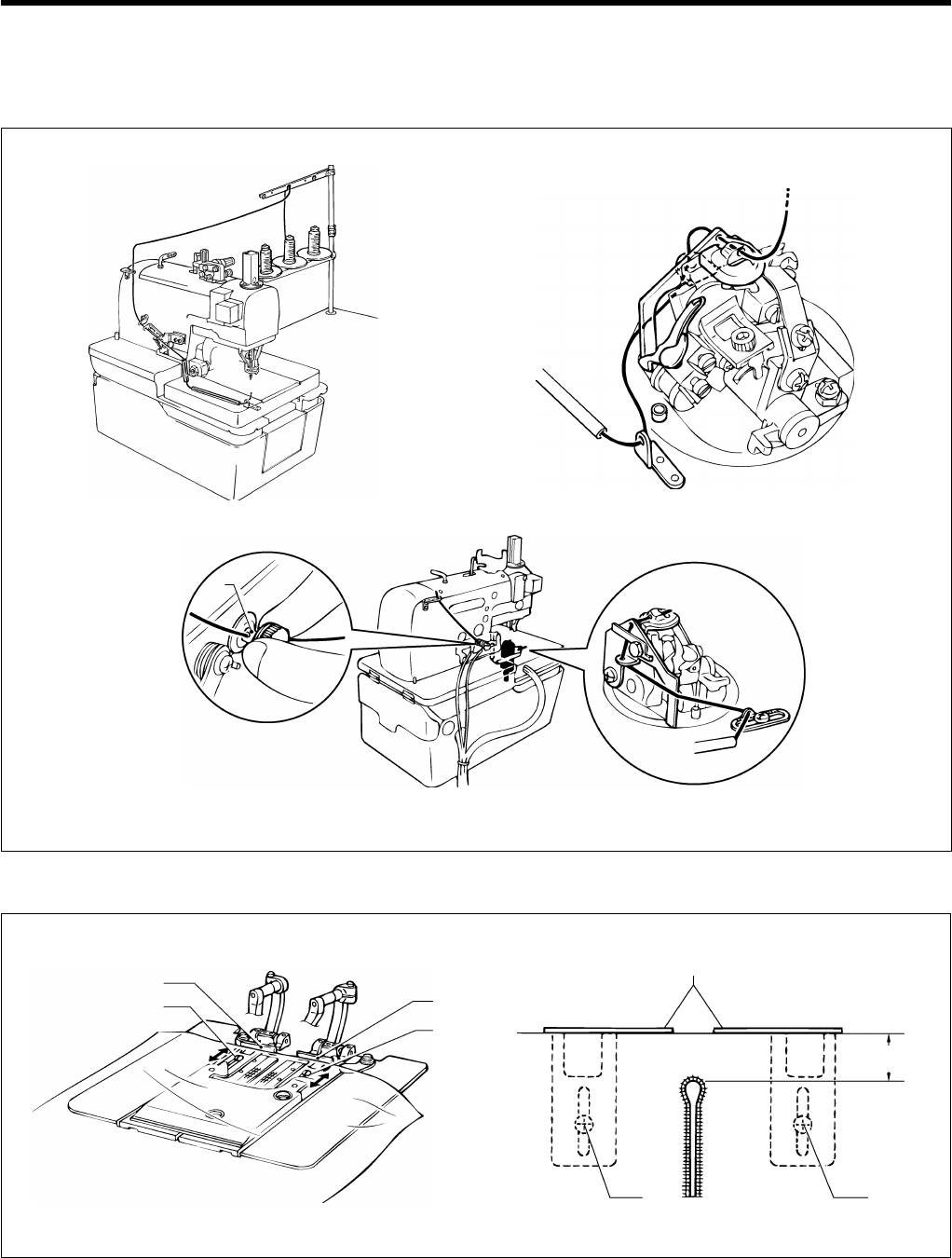
5-7. Threading the gimp
Remove the cloth presser plates (refer to page 13), and then thread the gimp as shown in the illustration below.
Once threading is complete, replace the cloth presser plates.
5-8. Setting the material
1. Insert the material so that it touches the right and left cloth guides (1).
2. The sewing margin can be adjusted to within 10 - 30 mm.
3. Loosen the screws (2) at left and right and move the cloth guides (1) back and forth to adjust the sewing margin.
<-00, -01>
<-02>
0884Q
0885Q
0886Q
Pass the gimp through the hole o
f
the thread tension stud (1).
Refer to “9-17. Adjusting the gimp length after trimming (-02)” (Page 54).
10 - 30 mm
(1)
(2) (2)
(1)
(2)
(1)
(2)
0889Q 0890Q
(1)
6. USING THE OPERATION PANEL AND FRONT PANEL
RH-9800 19
6.
USING THE OPERATION PANEL AND FRONT PANEL
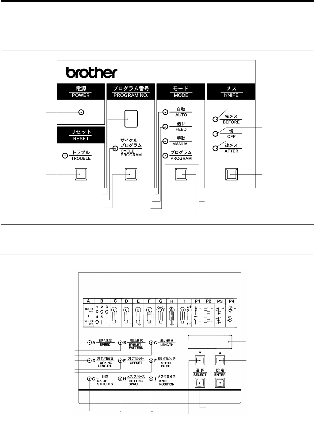
6-1. Panel button and switch names
Operation panel part names
Front panel part name
POWER indicator
(A) SPEED indicator
1127Q
TROUBLE indicator
RESET button
Program number display window
CYCLE PROGRAM indicator
PROGRAM NUMBER button
AUTO mode Indicator
FEED mode indicator
MANUAL mode
indicator
PROGRAM mode indicator
MODE button
KNIFE button
A
FTER indicato
r
OFF indicator
BEFORE indicator
(B) EYELET PATTERN indicator
(C) LENGTH indicator
(D) TACKING LENGTH indicator
(E) OFFSET indicator
(F) STITCH PITCH indicator
(M) SELECT button
(K) “Down” button
(I) KNIFE
POSITION indicator
(J) Front panel display
(L) “UP” button
(N) ENTER button
(H) CUTTING
SPACE
indicator
(G)No. OF
STITCHES
indicator
1126Q
6. USING THE OPERATION PANEL AND FRONT PANEL
RH-9800
20
If the power is turned on and the RESET switch is then pressed, the feed bracket will move to the cloth setting position.
Operations such as selecting a program number, changing the operation mode and selecting the cutting method can
then be carried out.
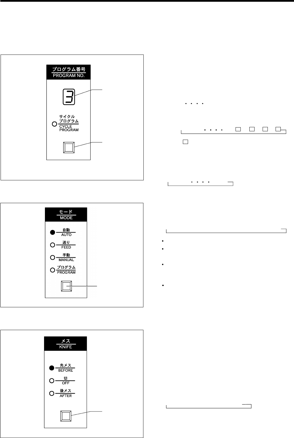
6-2. Selecting a program number
A maximum of nine different eyelet shapes can be programmed.
1. Press the PROGRAM NUMBER button (1). (Check
which of the mode indicator illuminates.)
In automatic, feed or manual mode, the program
numbers are displayed in the program number
display window (2) in the following order each time
the button is pressed.
→ 1→ 2 9
Note: If cycle programs have been input, the
sequence will be as follows:
→ 1 → 2 9→ → → →
( indicates a cycle program.)
* In programming mode, the program numbers are
displayed in the program number display window
(2) in the following order each time the button is
pressed.
→ 1 → 2 9 → C
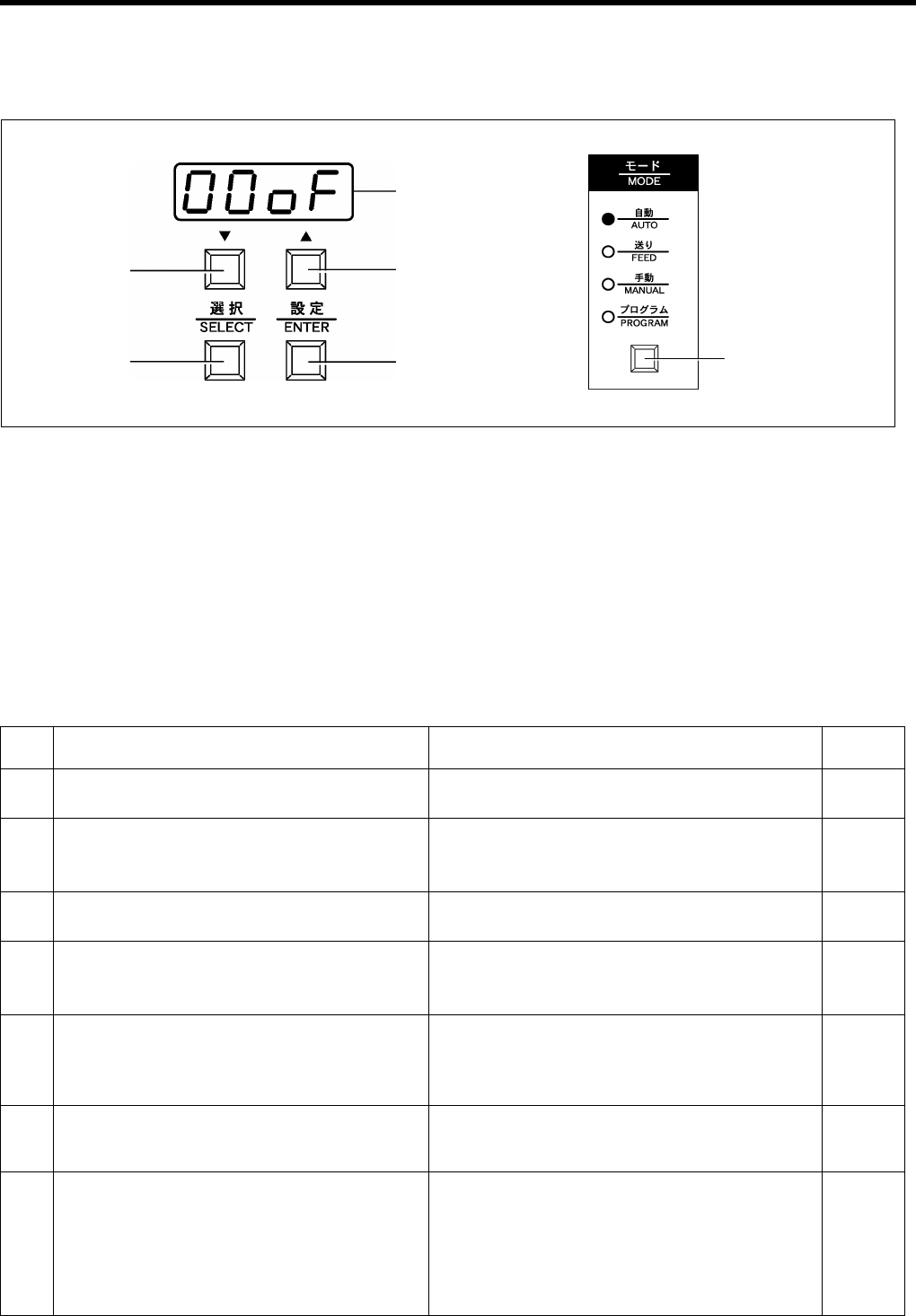
6-3. Changing the mode
1. Press the MODE button (1).
* The mode changes in the following order each time
the button is pressed.
→ AUTO → FEED → MANUAL → PROGRAM
Automatic mode is used for normal sewing.
Feed mode is used to move the feed bracket with
out sewing in order to check component positions.
Use the Manual mode to check the machine
operation when sewing by turning the upper shaft
pulley by hand.
Programming mode is used when setting
programs.
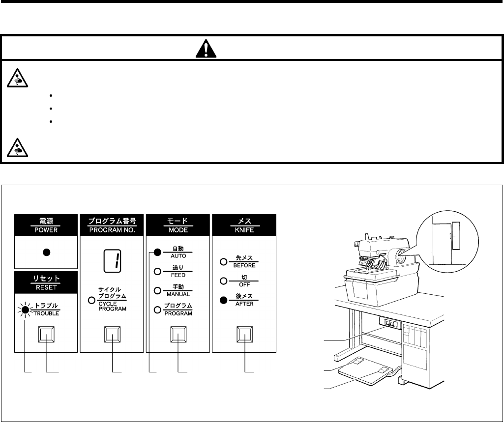
6-4. Changing the cutting timing
When "BEFORE" (cutting before sewing) is selected, the
knife operates before the buttonhole is sewn.
When "OFF" (no cutting) is selected, the knife does not
operate.
When "AFTER" (cutting after sewing) is selected, the
knife operates after the buttonhole is sewn.
1. Press the KNIFE button (1).
* The cutting timing changes in the following order
each time the button is pressed.
→BEFORE → OFF → AFTER
1128Q
(2)
(1)
1019Q
(1)
1129Q
(1)
6. USING THE OPERATION PANEL AND FRONT PANEL
RH-9800 21
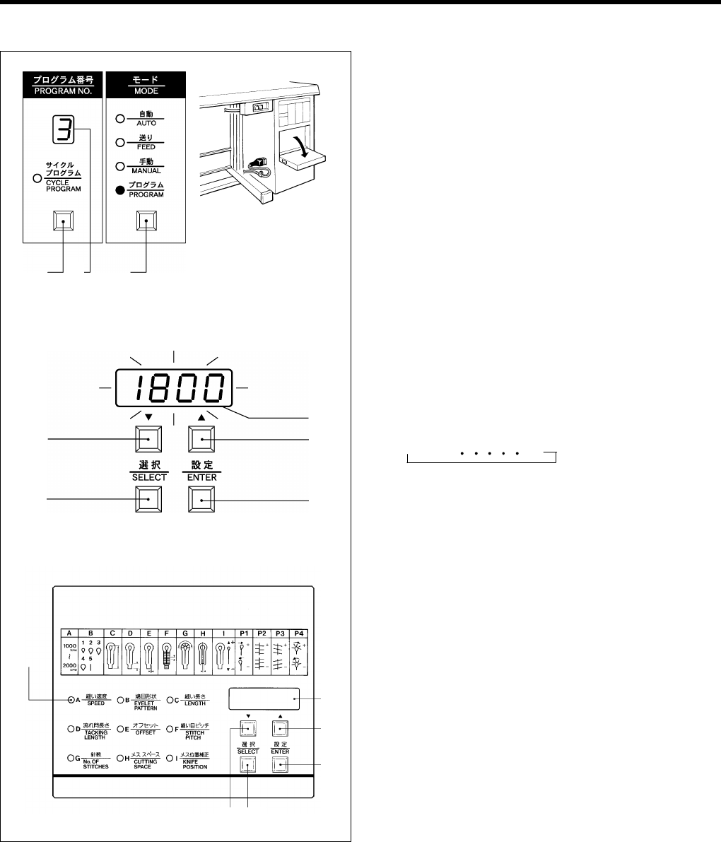
6-5. Setting a program
1. Push the section on the front panel marked "PUSH"
to open the front panel.
2. Press the MODE button (1) to switch to
programming mode.
Programming will not be possible unless the
PROGRAM indicator is illuminated.
* The SPEED indicator (A) will illuminate and the
current sewing speed appear on the front panel
display (J).
3. Press the PROGRAM NUMBER button (2) until the
desired program number appears in the program
number display window (3).
4. Press the SELECT button (M) to select a letter from
"A" to "P4."
* The character displayed changes in the following
order each time the button is pressed.
→A→ B P4
Then make the required settings by following steps 5.
and 6. below.
5. Press the "Up" button (L) or the "Down" button (K) to
change the setting value.
* When the setting value is changed, the numerals
appearing in the display will flash.
6. Press the ENTER button (N) to accept the changed
value.
* The display will stop flashing.
Note: If you press the SELECT button (M) or the
MODE button (1) while the display is still
flashing, the setting value will not be changed.
(J)
1130Q 1131Q
(3)
(2) (1)
(L)
(N)
(K)
(M)
(J)
(L)
(N)
(M)
(K)
(A)
1133Q
1132Q
6. USING THE OPERATION PANEL AND FRONT PANEL
RH-9800
22
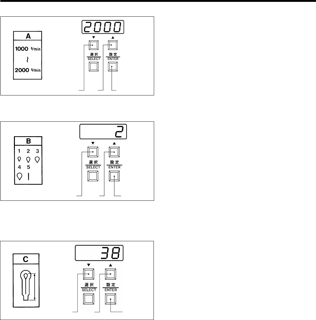
A.Setting the sewing speed 1. The sewing speed can be set to between 1000 - 2000
rpm in 11 100-rpm steps.
2. Press the "Up" button (L) or the "Down" button (K) to
set the desired sewing speed.
* When the setting value is being changed, the
numerals appearing in the display will flash.
3. Press the ENTER button (N) to accept the new sewing
speed setting.
* The display will stop flashing.
B.Setting the shape of the eyelet 1. The eyelet can be set to one of five different shapes in
accordance with the different shapes of knife.
The No. 2 knife is installed as the default knife for
standard specifications.
2. Select the same eyelet number as the number of the
knife which is being used.
3. Press the "Up" button (L) or the "Down" button (K) to
set the desired eyelet shape.
* When the setting value is being changed, the
numerals appearing in the display will flash.
4. Press the ENTER button (N) to accept the new eyelet
shape setting.
* The display will stop flashing.
C.Setting the buttonhole length <-00, -01>
1. The buttonhole can be set to a length of between 10
and 38 mm (10 to 50 mm with no looper thread
trimmer) in steps of 1 mm.
Note: You cannot set the buttonhole length to a
value that would make the difference between
the buttonhole length and the tacking length
less than 7 mm.
2. Press the "Up" button (L) or the "Down" button (K) to
set the desired buttonhole length.
* When the setting value is being changed, the
numerals appearing in the display will flash.
3. Press the ENTER button (N) to accept the new
buttonhole length setting.
* The display will stop flashing.
<-02>
The setting range is limited by the machine specifications (L1 - L7).
Example: For L1 specifications
1. The buttonhole can be set to a length of between 14 - 18 mm in steps of 1 mm.
Note: You cannot set the buttonhole length to a value that would make the difference between the buttonhole length
and the tacking length less than 7 mm.
2. Press the "Up" button (L) or the "Down" button (K) to set the desired buttonhole length.
* When the setting value is being changed, the numerals appearing in the display will flash.
3. Press the ENTER button (N) to accept the new buttonhole length setting.
* The display will stop flashing.
The buttonhole lengths for L2 - L7 specifications can also be set in steps of 1 mm.
1135Q
1134Q (N)(L)(K)
1137Q
1136Q (N)(L)(K)
1139Q
1138Q (N)
(L)
(K)
6. USING THE OPERATION PANEL AND FRONT PANEL
RH-9800 23
D.Setting the tacking length 1. The tacking length can be set to between 3 and 43
mm in steps of 1 mm.
2. If not adding tacking, set the tacking length to "0". If
this is done, it will not be possible to set a value for the
offset.
Note: You cannot set the tacking length to a value
that would make the difference between the
buttonhole length and the tacking length less
than 7 mm.
3. Press the "Up" button (L) or the "Down" button (K) to
set the desired tacking length.
* When the setting value is being changed, the
numerals appearing in the display will flash.
4. Press the ENTER button (N) to accept the new tacking
length setting.
* The display will stop flashing.
E.Setting the offset 1. The offset can be set to between 0.5 and 2 mm in
steps of 0.1 mm.
* The offset should normally be set to half the stitch
width.
If a tacking length that is outside the 0 - 3 mm range
is set, it will be set back to 1.5 mm automatically.
2. Press the "Up" button (L) or the "Down" button (K) to
set the desired offset.
* When the setting value is being changed, the
numerals appearing in the display will flash.
3. Press the ENTER button (N) to accept the new offset
setting.
* The display will stop flashing.
Example: If the stitch width is 3 mm, set the offset to
3 mm ÷ 2 = 1.5 mm.
However, fine adjustments to this value
may be necessary depending on the
material and/or the thread tension.
F. Setting the stitch pitch 1. The stitch length can be set to between 0.5 and 2 mm
in steps of 0.1 mm.
2. Press the "Up" button (L) or the "Down" button (K) to
set the desired stitch length.
* When the setting value is being changed, the
numerals appearing in the display will flash.
3. Press the ENTER button (N) to accept the new stitch
length setting.
* The display will stop flashing.
1140Q 1141Q
C
D
1143Q
1142Q
EStitch
width
1145Q
1144Q
(L)
(N)
(K)
6. USING THE OPERATION PANEL AND FRONT PANEL
RH-9800
24
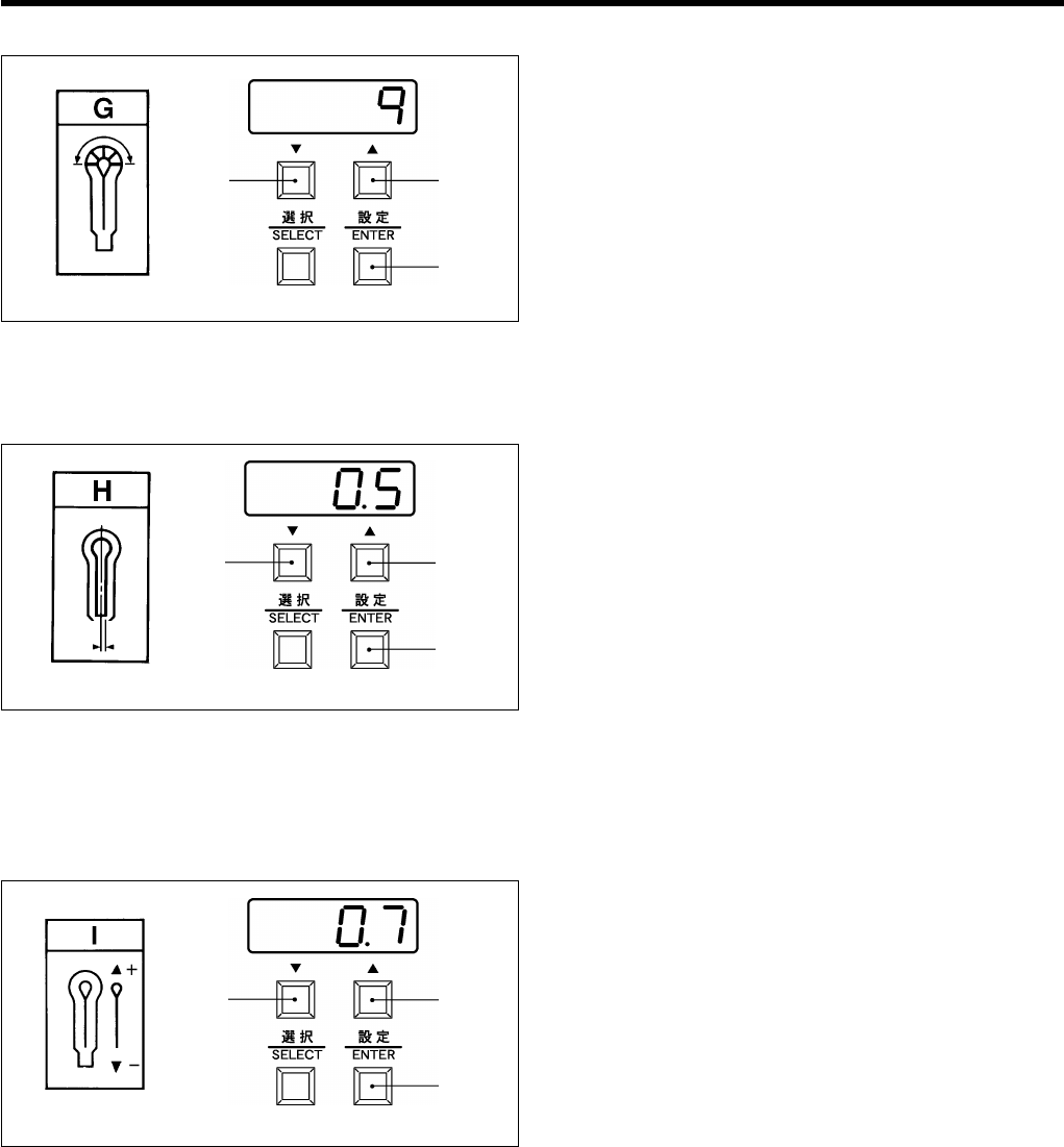
G. Setting the number of eyelet stitches 1. The number of eyelet stitches can be set to between 4
and 20 stitches in steps of 1 stitch.
2. Press the “Up” button (L) or the "Down" button (K) to
set the desired number of eyelet stitches.
* When the setting value is being changed, the
numerals appearing in the display will flash.
3. Press the ENTER button (N) to accept the new eyelet
stitch number setting.
* The display will stop flashing.
H. Setting the cutting space 1. The cutting space can be set to between -0.3 and 0.5
mm in steps of 0.1 mm.
Note: You cannot set the cutting space to a value
that would make the difference between the
knife position compensation and the cutting
space less than -0.7 mm.
2. Press the “Up” button (L) or the " Down" button (K) to
set the desired cutting space.
* When the setting value is being changed, the
numerals appearing in the display will flash.
3. Press the ENTER button (N) to accept the new cutting
space setting.
* The display will stop flashing.
I. Setting the knife position compensation 1. The knife position compensation can be set to
between -0.7 and +0.7 mm in steps of 0.1 mm.
* If you would like to move the knife closer to the
seam, set to a negative value; if you would like to
move it away from the seam, set to a positive value.
Note: You cannot set the knife position
compensation to a value that would make the
difference between the knife position
compensation and the cutting space less than
-0.7 mm.
2. Press the "Up" button (L) or the "Down" button (K) to
set the desired knife position compensation.
* When the setting value is being changed, the
numerals appearing in the display will flash.
3. Press the ENTER button (N) to accept the new knife
position compensation setting.
* The display will stop flashing.
1147Q
1146Q
(L)
(N)
(K)
1148Q 1149Q
(L)
(N)
(K)
1150Q 1151Q
(L)
(N)
(K)
6. USING THE OPERATION PANEL AND FRONT PANEL
RH-9800 25
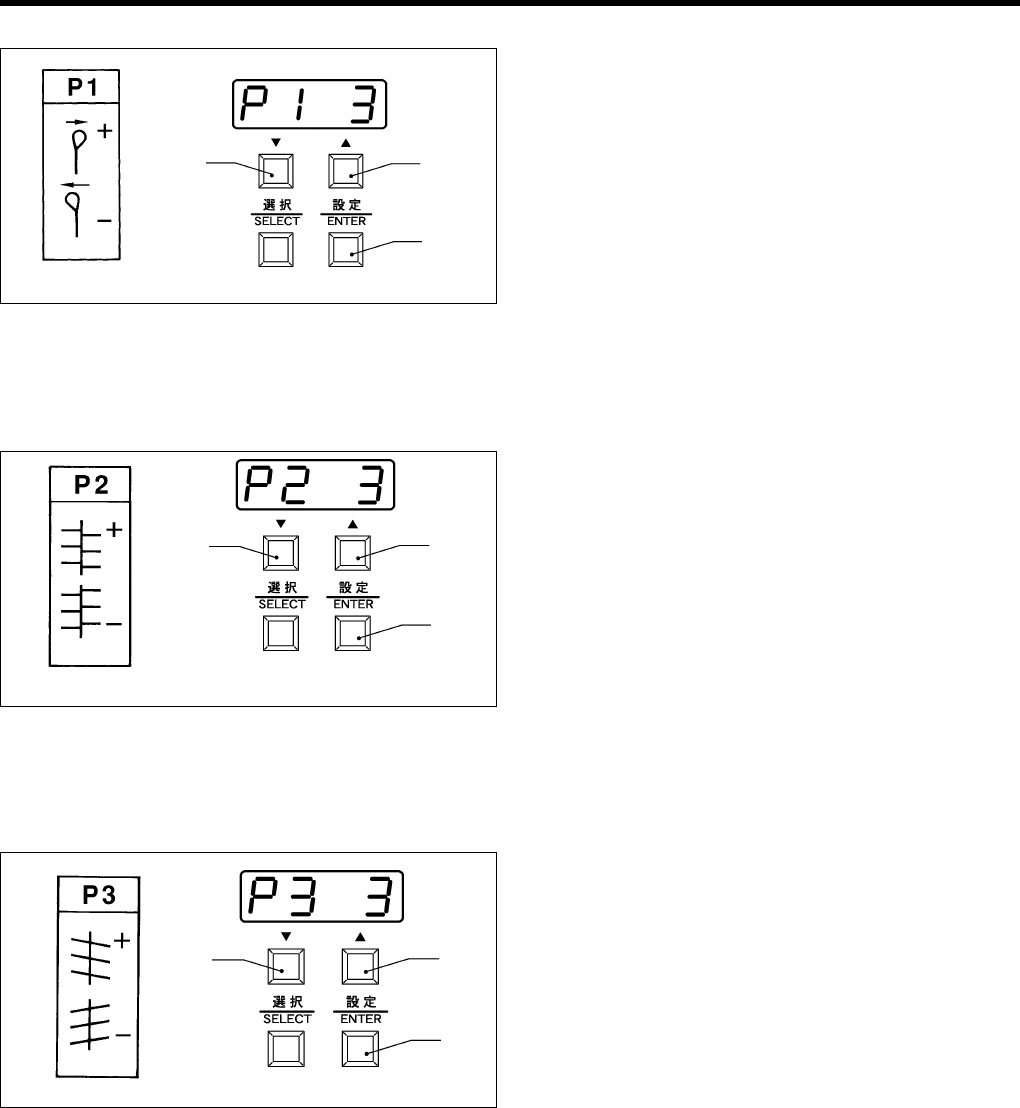
P1. Setting X correction 1. The setting range is from 1 to 6 in steps of 1.
* Set to a larger value if you would like to move the
eyelet seam to the right (when seen from the
finished side, or the reverse side when sewing).
2. Press the “up” button (L) or the “down” button (K) to
set the X correction value.
* When the setting value is changed, the value
displayed will start to flash.
3. Press the ENTER button (N) to accept the X
correction setting.
* The display will stop flashing and will start
illuminating steadily.
P2. Setting Y correction 1. The setting range is from 1 to 6 in steps of 1.
* Set to a larger value if you would like to move the
right-side seam further forward (when seen from
the finished side, or the reverse side when sewing).
2. Press the “up” button (L) or the “down” button (K) to
set the Y correction value.
* When the setting value is changed, the value
displayed will start to flash.
3. Press the ENTER button (N) to accept the Y
correction setting.
* The display will stop flashing and will start
illuminating steadily.
P3. Setting θ1 correction 1. The setting range is from -3 to 3 in steps of 1.
* Set to a larger value if you would like to rotate the
seam which is not part of the eyelet clockwise
(when seen from the finished side, or the reverse
side when sewing).
2. Press the “up” button (L) or the “down” button (K) to
set the θ1 correction value.
* When the setting value is changed, the value
displayed will start to flash.
3. Press the ENTER button (N) to accept the θ1
correction setting.
* The display will stop flashing and will start
illuminating steadily.
1152Q 1153Q
(L)
(N)
(K)
1154Q 1155Q
(L)
(N)
(K)
1156Q 1157Q
(L)
(N)
(K)

6. USING THE OPERATION PANEL AND FRONT PANEL
RH-9800
26
P4. Setting θ 2 correction 1. The setting range is from -3 to 3 in steps of 1.
* Set to a larger value if you would like to rotate the
eyelet seam clockwise (when seen from the
finished side, or the reverse side when sewing).
2. Press the “up” button (L) or the “down” button (K) to
set θ 2 correction value.
* When the setting value is changed, the value
displayed will start to flash.
3. Press the ENTER button (N) to accept the θ2
correction setting.
* The display will stop flashing and will start
illuminating steadily.
1158Q 1159Q
(L)
(N)
(K)
6. USING THE OPERATION PANEL AND FRONT PANEL
RH-9800 27
6-6. Using the memory switch
The conditions of the memory switches are memorized even if the power is OFF, however, if data of the memory
switches are initialized, the memory switches will be returned to their initial settings (factory default settings).
1. While pressing the SELECT button (M), press the power switch to turn on the power.
* The two left-side columns of the front panel display (J) are the memory switch number, and the two right-side
columns show the memory switch setting (or value).
2. Press the SELECT button (M) to select the desired memory switch number.
* The setting range is from 00 to 99. However, numbers in unused ranges are skipped.
3. Press the “UP” button (L) or “DOWN” button (K) to select the desired memory switch number.
* For memory switches which can be set to ON or OFF, press the "UP" button (L) to set to "On", and press the
"DOWN" button (K) to set to "OF". "On" represents ON, and "OF" represents OFF.
4. Press the ENTER button (N) to store the memory switch setting.
5. Press the MODE button (1).
* The TROUBLE indicator will flash and the sewing machine will go to normal standby mode.
No. Contents Setting range Initial
value
00 Bar tacking at the sewing start to prevent fraying OFF: Disabled
ON: Enabled OFF
01 Number of stitches for memory switch No. 00
* Does not appear when memory switch No. 00
is set to OFF.
01: 1 stitch
02: 2 stitches
03: 3 stitches
01
02 Bar tacking at the sewing end to prevent fraying OFF: Disabled
ON: Enabled OFF
03 Number of stitches for memory switch No. 02
* Does not appear when memory switch No. 02
is set to OFF.
01: 1 stitch
02: 2 stitches
03: 3 stitches
01
04
Work clamp operation selection when feed
bracket is at front position
(Set to OFF if the cutting block may strike the
Work clamp.)
OFF: The work clamp passes underneath the cutting
block, then rises and moves forward.
ON: The work clamp rises and then moves
forward.
OFF
05 Eyelet buttonhole sewing speed setting OFF: Same speed as speed A set at the front panel.
ON: Different speed from speed A set at the front
panel.
OFF
06
Speed for memory switch No. 05
(If the speed is set to a higher value than
speed A that has been set at the front panel,
the speed will not exceed speed A.)
* Does not appear when memory switch No. 05
is set to OFF.
10: 1,000rpm, 11: 1,100rpm, 12: 1,200rpm,
13: 1,300rpm, 14: 1,400rpm, 15: 1,500rpm,
16: 1,600rpm, 17: 1,700rpm, 18: 1,800rpm,
19: 1,900rpm, 20: 2,000rpm
18
(J)
(L)
(N)
(K)
(M) (1)
1019Q
1160Q

6. USING THE OPERATION PANEL AND FRONT PANEL
RH-9800
28
No. Contents Setting range Initial
value
07 Y direction offset for return seam to prevent
thread breakage OFF: No offset
ON: Offset by 1/2 pitch OFF
08 Sewing end pitch for buttonhole taper to
prevent fraying OFF: No change
ON: Change OFF
09
No. of stitches before pitch change for memory
switch No. 08
* Does not appear when memory switch No. 08
is set to OFF.
01: 1 stitch, 02: 2 stitches, 03: 3 stitches,
04: 4 stitches, 05: 5 stitches 01
10
No. of stitches after pitch change for memory
switch No. 08
* Does not appear when memory switch No. 08
is set to OFF.
01: 1 stitch, 02: 2 stitches, 03: 3 stitches,
04: 4 stitches, 05: 5 stitches, 06: 6 stitches,
07: 7 stitches, 08: 8 stitches, 09: 9 stitches 01
11 Test feeding speed OFF: Standard speed
ON: Low speed OFF
12 Speed for memory switch No. 11
* Does not appear when memory switch No. 11
is set to OFF.
20: 20% of standard speed
35: 35% of standard speed
50: 50% of standard speed 50
13 Knife operation (BEFORE/OFF/AFTER) setting OFF: Setting not possible within cycle program
ON: Setting possible within cycle program OFF
14 Special lapel cutting device OFF: Disabled
ON: Enabled OFF
15 Button hole sensor (Special lapel cutting
device)
OFF: Disabled
ON: Enabled OFF
16 Timer for checking lowering of cutting block
(Timer for determining if cutting block is
lowered)
OFF:Disabled (Determined from slit signal
stopping)
ON: Enabled (Determined by timer) OFF
17 Time for memory switch No. 16
* Does not appear when memory switch No. 16
is set to OFF.
42: 420 ms, 45: 450ms, 48: 480ms,
51: 510ms, 54: 540 ms 45
18 Changing cutting block ON time
* Disabled (always "OFF") when memory
switch No. 16 is "ON"
OFF: Disabled (25 ms)
ON: Enabled OFF
19 Time for memory switch No. 18
* Does not appear when memory switch No. 18
is set to OFF.
05: 50 ms, 10: 100ms,
15: 150ms, 20: 200 ms 05
20
Timer for checking raising of cutting block
(Timer for determining if the cutting block has
been raised to a position where it will not touch
the next feed bracket to operate)
OFF: Disabled (Determined from number of slit
signals)
ON: Enabled (Determined by timer) OFF
21 Time for memory switch No. 20
* Does not appear when memory switch No. 20
is set to OFF.
15: 150ms, 20: 200 ms, 25: 250ms,
30: 300ms, 35: 350ms, 40: 400ms,
45: 450ms, 50: 500ms 20
22
Cutting block raising check timer
(Raised position of the cutting block is
determined from the number of slit signals, and
timer is updated)
* Disabled (always "OFF") when memory
switch No. 20 is "ON"
OFF: Disabled
ON: Enabled OFF
23 Time for memory switch No. 22
* Does not appear when memory switch No. 22
is set to OFF.
05: 50 ms, 10: 100ms, 15: 150ms,
20: 200 ms, 25: 250ms, 30: 300ms,
35: 350ms, 40: 400ms 05
24 Setting tacking length to 0 for straight tacking
specifications OFF: Disabled
ON: Enabled OFF
25
99 Spare - -

6. USING THE OPERATION PANEL AND FRONT PANEL
RH-9800 29
6-7. List of error codes
If the buzzer sounds and an error code starting with "E" appears in the front panel display, check according to
the table below.
Codes E-00 to E-16 are errors which are displayed when the power is turned on. Codes E-30 to E-59 are resetting errors
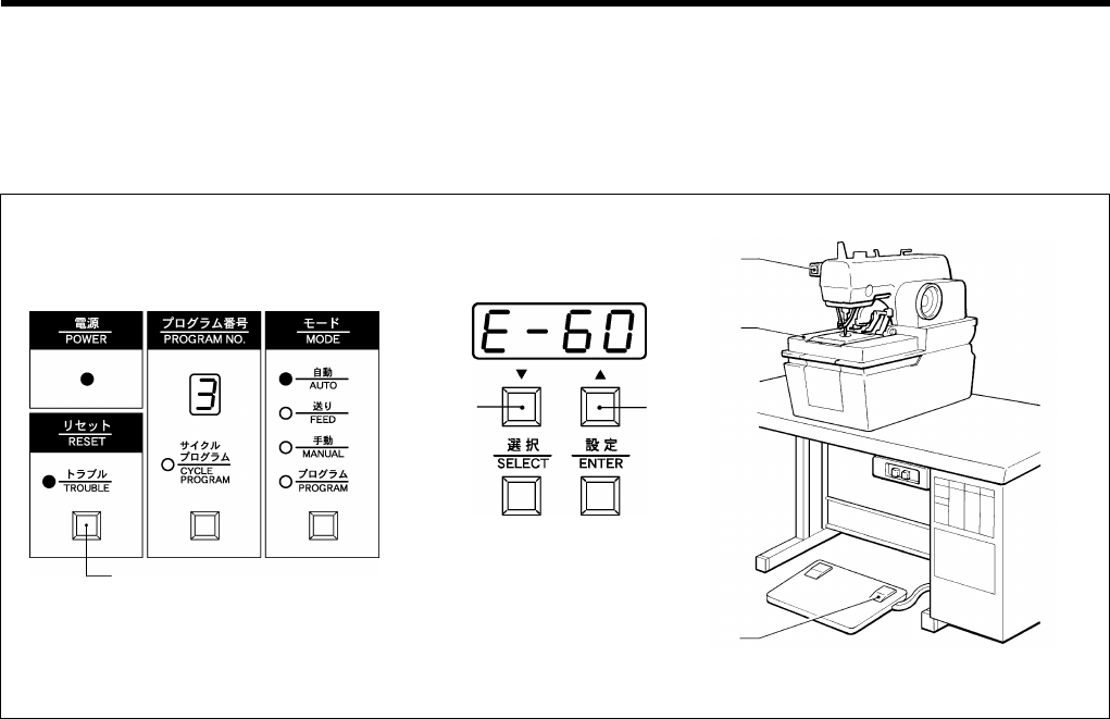
which are displayed before operation and after the EMERGENCY STOP switch is pressed. Codes E-60 to E-89
represent errors which occur during operation.
Code Explanation Resetting method
E-00 EMERGENCY STOP switch was pressed.
Press the EMERGENCY STOP switch once
more and then press the RESET button.
E-02 Machine head is raised (safety switch is off). Turn off the power.
E-03 Cloth presser switch was pressed. Release the cloth presser switch and then
press the RESET button.
E-04 Start switch was pressed. Release the start switch and then press
the RESET button.
E-05 RESET button was pressed. Turn off the power.
E-09 Sewing specifications changeover harness and stitch length
changeover harness and PROM version do not match. Turn off the power.
E-10 Needle bar is not at the highest position. Raise the needle to the needle up position
and then press the RESET button.
E-12 Cutting block is lowered. Turn off the power.
E-15 Lower thread and gimp trimming knife does not retract. Turn off the power.
E-16 Upper thread trimming knife does not retract. Turn off the power.
E-30 EMERGENCY STOP switch was pressed.
Press the EMERGENCY STOP switch once
more and then press the RESET button.
E-32 Machine head is raised (safety switch is off). Turn off the power.
E-35 RESET button was pressed. Turn off the power and then press the
RESET button.
E-40 Needle bar has not been raised. Raise the needle to the needle up position
and then press the RESET button.
E-42 Cutting block is lowered. Turn off the power.
E-45 Lower thread and gimp trimming knife does not retract. Turn off the power.
E-46 Upper thread trimming knife does not retract. Turn off the power.
E-50 X axis is not at the home position. Turn off the power.
E-51 Y axis is not at the home position. Turn off the power.
E-52 θ axis is not at the home position Turn off the power.
E-59 Sewing data has been corrupted (checked for each program). Turn off the power.
E-60 EMERGENCY STOP switch was pressed. Press the RESET button (to interrupt) or
the start switch (to continue).
E-62 Machine head is raised (safety switch is off). Turn off the power.
E-69 Needle bar does not stop at the highest position.
Raise the needle to the needle up position
and then press the start switch (to continue).
E-70 Needle up signal does not turn on and off during operation. Turn off the power.
E-71 Needle down signal does not turn on and off during operation. Turn off the power.
E-72 Cutting block operation is incorrect. Turn off the power.
E-75 Lower thread and trimming operations are incorrect. Turn off the power.
E-76 Upper thread operation is incorrect. Turn off the power.
E-80 When the feed bracket returns to the home position, the X axis is
not at the home position. Turn off the power.
E-81 When the feed bracket returns to the home position, the Y axis is
not at the home position. Turn off the power.
E-82 When the feed bracket returns to the home position, the θ axis is
not at the home position. Turn off the power.
E-89 Machine operation direction is reversed. Turn off the power.
E-91 Pulse motor overcurrent Turn off the power.
Note: Errors E-50, E-51 and E-52 are not errors to be reset after the EMERGENCY STOP switch is pressed.
7. SEWING
RH-9800
30
7. SEWING
Make sure you know where the EMENRGENCY STOP switch is and how it is used before operating the sewing
machine.
7-1. Using the EMERGENCY STOP switch
In automatic mode
1. Press the EMERGENCY STOP switch (1).
* All machine operations will stop and the buzzer will sound. The TROUBLE indicator will illuminate and "E-60" will
appear on the front panel display at this time.
2. Eliminate the cause of the problem.
* The machine will not always stop in the needle up position if the EMERGENCY STOP switch (1) is pressed during
sewing.
Turn the upper shaft pulley by hand to raise the needle to the needle up position (so that the marks are aligned).
* The feed bracket (2) can be moved back and forth at this time by pressing the "up" button (L) and "Down" button
(K).
3. To continue sewing, press the start switch (3).
* The TROUBLE indicator will switch off, the "E-60" will be cleared from the front panel display and sewing will begin
again.
To stop sewing, press the RESET button (4).
* The TROUBLE indicator will switch off, the "E-60" will be cleared from the front panel display and the feed bracket
will return to the cloth setting position.
In manual mode or in automatic mode
1. Press the EMERGENCY STOP switch (1).
* All machine operations will stop and the buzzer will sound. The TROUBLE indicator will illuminate and "E-60" will
appear on the front panel display at this time.
2. Eliminate the cause of the problem.
3. Press the RESET button (4).
* The TROUBLE indicator will switch off, the "E-60" error code will be cleared from the front panel display and the
feed bracket will return to the cloth setting position.
1161Q 1163Q
1162Q
(4)
(L)(K)
(1)
(2)
(3)
7. SEWING
RH-9800 31
7-2. Sewing
CAUTION
Turn off the power switch at the following times, otherwise the machine may operate if the start switch is pressed
by mistake, which could result in injury.
When threading the needle
When replacing the needle
When not using the machine and when leaving the machine unattended
Do not touch any of the moving parts or press any objects against the machine while sewing, as this may result
in personal injury or damage to the machine.
When carrying out automatic sewing for the first time, be sure to carry out a test sewing first.
1. Press the power switch (1) to turn on the power.
* The POWER indicator will illuminate and the TROUBLE indicator (2) will flash.
2. Press the RESET button (3).
* The TROUBLE indicator (2) will switch off and the feed bracket will move to the cloth setting position.
* If the buzzer sounds and "E-10" appears on the front panel display (J) at this time, turn the pulley to set the needle
to its upper position, and press the RESET button (3).
3. Press the PROGRAM NUMBER button (4) to select the desired program number. (Refer to page 20.)
4. Press the MODE button (5) to switch to automatic mode.
* The AUTO indicator (6) will illuminate.
5. Press the KNIFE button (7) to select cutting before sewing, OFF (no cutting) or cutting after sewing. (Refer to page 20.)
6. Place the material to be sewn under the cloth presser and press the cloth presser switch (8) to lower the cloth presser,
and then release the cloth presser switch (8).
7. Press the start switch (9). Sewing will then start.
8. When sewing is finished, the cloth presser will be raised.
To repeat this operation, repeat steps 6. and 7. above.
Note: After you have finished the machine and have turned the power off, the previous sewing data will still be
retained in memory even when the power is turned back on again. Thus you can continue with the same type
of sewing.
Check the thread tension after sewing. Refer to the following page.
1164Q 1165Q
(1)
(8)
(2) (3) (4) (6) (5) (7)
(9)
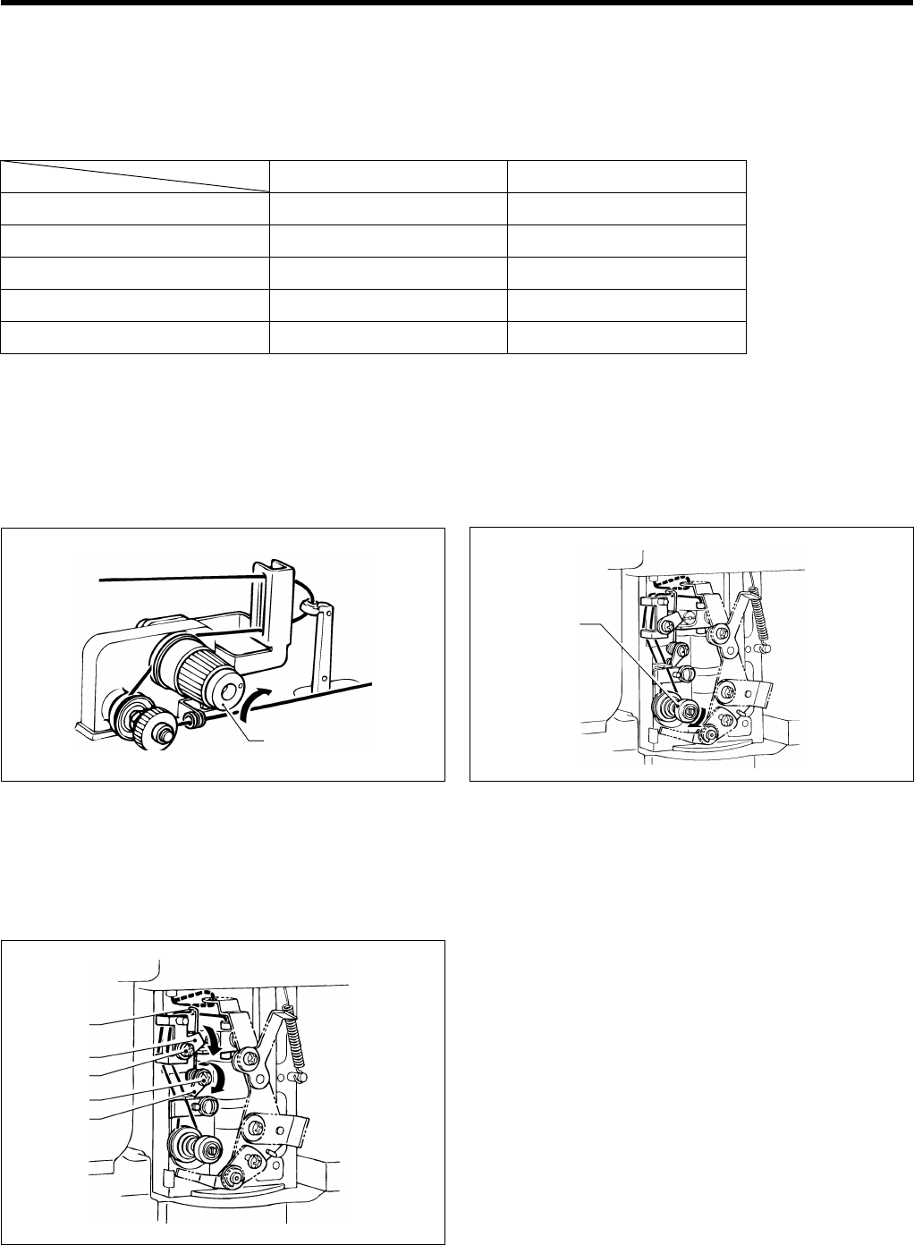
7. SEWING
RH-9800
32
7-3. Adjusting the thread tension
Turn off the power.
Never adjust the thread tension while sewing.
<Reference values>
Woolen materials + wool gimps
Denim (3 layers)
Upper thread tension 0.9 N 1.0 N
Lower thread tension 0.3 N 0.8 N
Thread take-up spring tension 0.05 N 0.07N
Thread take-up spring stroke 8 mm 8 mm
Upper and lower thread # 30 polyester # 30 cotton
* If you change the type of material being used, it may be necessary to change the thread tension.
The upper thread tension given above is the tension when the upper thread is pulled out from the thread path hole of
the thread take-up lever, and the lower thread tension is when the lower thread is pulled out from the needle hole in the
throat plate.
Upper thread tension Lower thread tension
Adjusting the lower thread take-up spring tension and stroke
Tension adjustment
Loosen the screw (3) and turn the thread take-up spring
support (4) in the direction indicated by the arrow to
increase the tension of the spring (5).
Stroke adjustment
Loosen the screw (6) and turn the thread take-up spring
guide (7) in the direction indicated by the arrow to
increase the stroke of the spring (5).
0934Q
0933Q
(1)
(2)
Turn the upper thread tension adjustment knob (1) in the
direction indicated by the arrow to increase the uppe
r
thread tension.
Turn the lower thread tension adjustment knob (2) in the
direction indicated by the arrow to increase the lower thread
tension.
(4)
0935Q
(3)
(6)
(7)
(5)
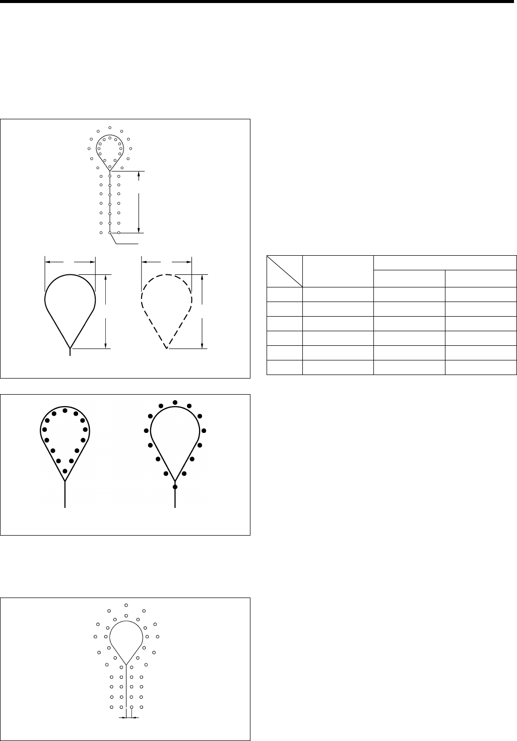
7. SEWING
RH-9800 33
7-4. Needle and knife position
The feed bracket is electronically controlled by means of pulse motors.
It is not necessary to change the position of the knife when switching between cutting before sewing and cutting after sewing.
It is not necessary to change the needle down position in order to keep enough space for cutting when cutting after
sewing has been selected.
Relationship between knife position and eyelet shape
1. When cutting before sewing, the inside needle down
position must be aligned accurately with the straight
line section of the eyelet (when the cutting space H is
0).
This is set correctly at the time of shipment from the
factory.
2. The shape of the eyelet is automatically changed
according to the shape of the knife for cutting before
and after sewing and for no cutting.
Eyelet shape (c X d)
Knife No.
Cutting shape
(a X b) Cutting before sewing
or off (no cutting) Cutting after sewing
1 2.1 X 3.2 1.9 X 2.8 2.4 X 3.9
2 2.8 X 4.3 2.4 X 3.9 3.3 X 4.6
3 3.0 X 4.6 3.2 X 4.1 3.6 X 4.8
4 3.2 X 5.4 2.8 X 4.7 3.6 X 6.1
5 Straight Straight Straight
6 3.8 X 4.3 3.2 X 3.6 4.0 X 4.5
3. At the time of shipment, the installation position for the
knife is adjusted to the position shown in the
illustration at left (when the cutting space H and the
knife position compensation value I are "0").
Explanation of the cutting space function
When cutting after sewing, this function moves the outer needle down positions in accordance with the knife shape so
that the seam is not cut by the knife.
1. When cutting after sewing, set the cutting space H to an
appropriate value so that the seam is not cut by the knife.
* The cutting space H should generally be set to
around 0.2 - 0.3. (Refer to page 24 for details on the
setting method.)
* The knife position compensation value I should be
set to "0".
Refer to "H. Setting the cutting space" and "I.
Setting the knife position compensation".
Strai
g
ht section
0936Q
a c
b d
Cutting shape (a X b) E
y
elet sha
p
e
(
c X d
)
Knife
0937Q
(When cutting before sewing) (When cutting after sewing)
Cutting space
0938Q
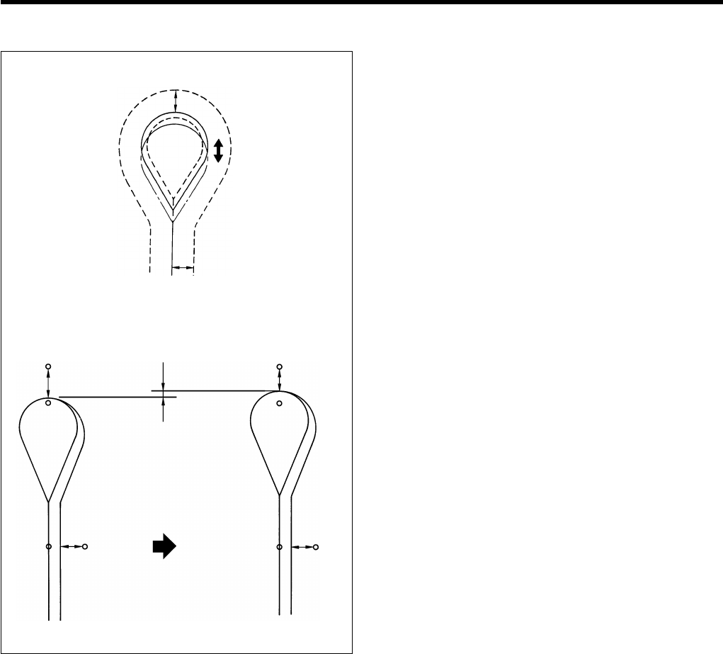
7. SEWING
RH-9800
34
Knife position compensation function
This function moves the knife with respect to the seam in
order to ensure that distances a and a' are equal.
1. When cutting before sewing, the difference between a
and a' will change depending on the cloth opening
amount.
2. Set the knife position compensation value I so that the
two are equal.
(Move the knife to the positive direction (+) when
increasing the cloth opening amount.
Refer to "I. Setting the knife position compensation" on
page 24.)
1166Q
a
a’
1167Q
Knife position
compensation
aa
a’ a’
a < a’ a = a’
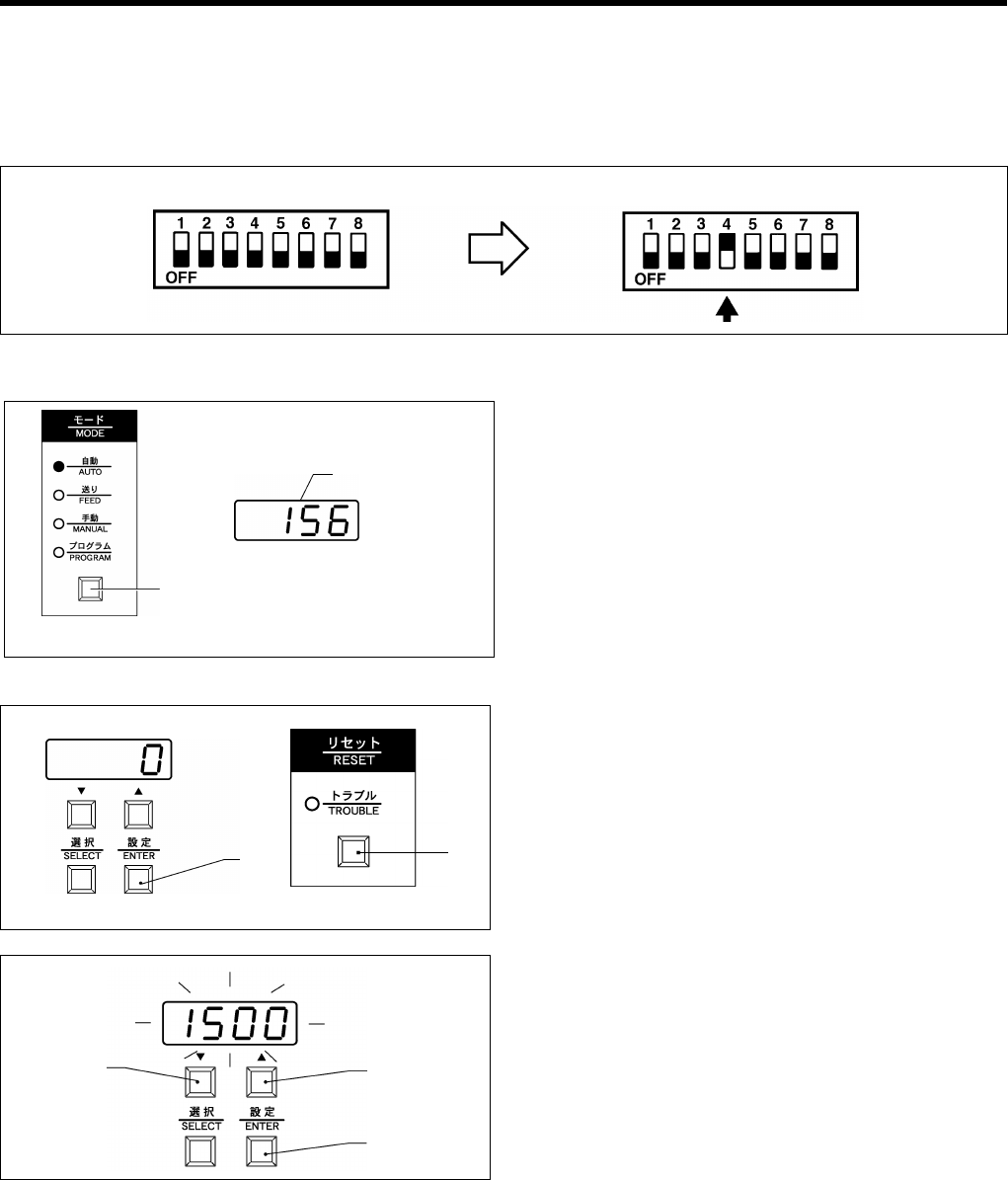
7. SEWING
RH-9800 35
7-5. Using the production counter
The production counter is initially set to the counting up from zero method. It can display up to a maximum count of 9999.
* If DIP switch No. 4 inside the front panel is set to OFF, the counting up from zero method will be used. If DIP switch
No. 4 is set to ON, the counting down to zero method will be used.
Displaying the production counter 1. Press the MODE button (1) to switch to automatic
mode.
* The production counter will appear in the front
panel display (J).
Resetting the production counter Counting up from zero method
1. Press the MODE button (1) to switch to automatic mode.
2. Press the ENTER button (N).
* The units digit will start flashing in the display.
3. Press the RESET button (2).
* The units digit will change to "0" and the counter
value will be reset to "0".
Counting down to zero method
1. Press the MODE button (1) to switch to automatic mode.
2. Press the ENTER button (N).
* The units digit will start flashing in the display.
3. Press the "Up" button (L) or the "Down" button (K) to
set the value for the units column, and then press the
ENTER button (N).
Repeat this step for the tens, hundreds and thousands
columns.
* The production counter function can be stopped by
setting counter to “0000”.
* When the thousands column has been set, the
machine will return to normal automatic mode.
Note: If the counting down to zero method is used, further sewing will not be possible when the production counter
reaches "0", so a number greater than zero should always be set. The production counter can be returned to
the initial setting value simply by pressing the ENTER button (N).
* If you would like to change the production counter setting due to sewing errors, use the counting down to zero
setting procedure to set the production counter.
Standard position (Counting up from zero method) Reset position (Counting down to zero method)
1168Q
1019Q
(1)
(J)
1169Q
1170Q
(N) (2)
1171Q
1172Q
(K) (L)
(N)
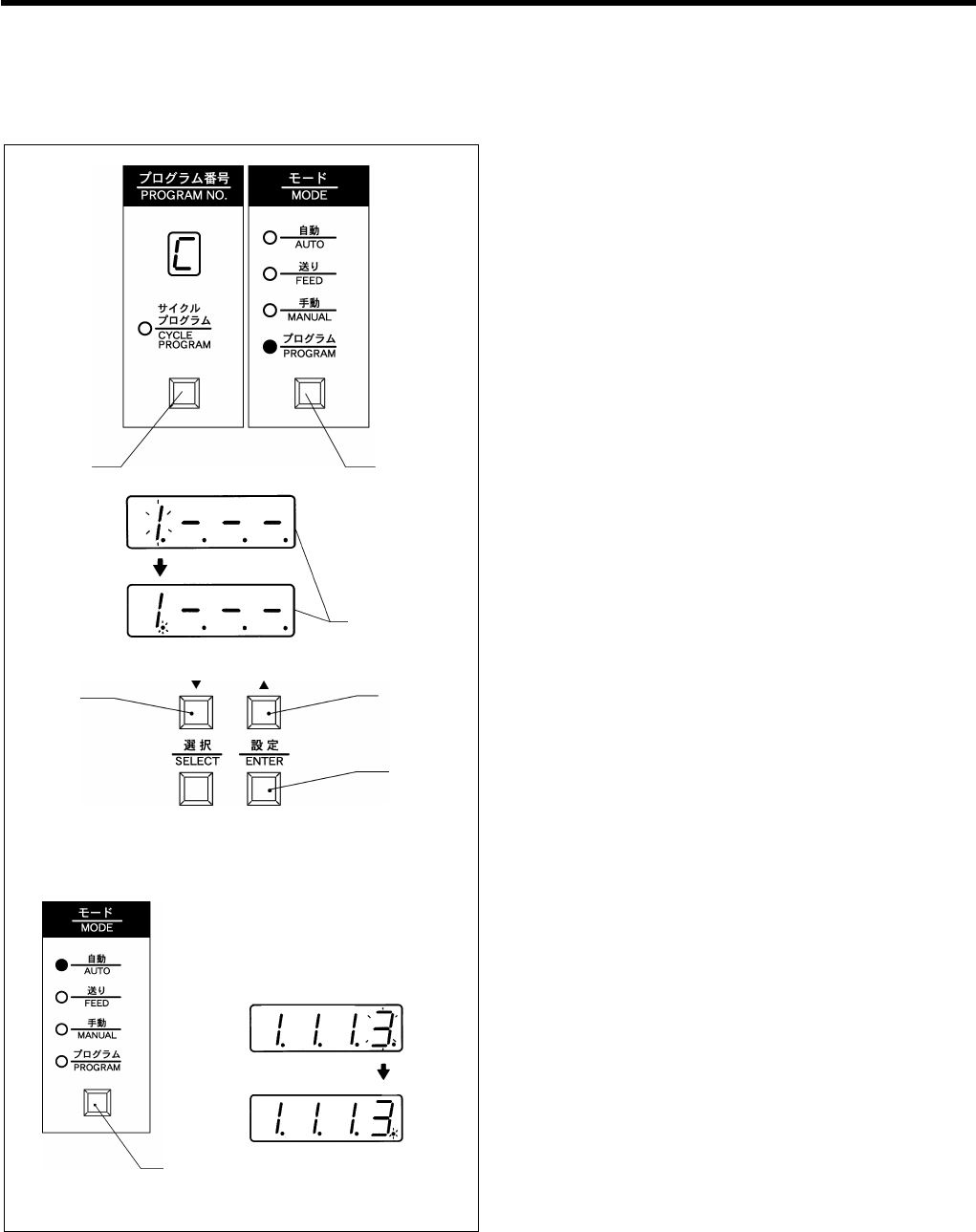
7. SEWING
RH-9800
36
7-6. Using a cycle program
This example shows the procedure for a cycle program which runs program 1 (with the knife operating) three times and
program 3 (with the knife not operating) once.
Programming procedure
1. Press the MODE button (1) to switch to programming
mode.
2. Keep pressing the SELECT button (2) until " C "
appears in the program number display window.
* The number in the thousands column of the front
panel display (J) will start flashing at this time.
3. Press the "Up" button (L) or the "Down" button (K) to
change the value in the thousands column to "1", and
then press the ENTER button (N).
* Program number 1 will now be set, and the dot in
the thousands column will flash.
4. Change the flashing interval so that the illumination
time for the dot is longer than the switched-off time.
* Press the "Up" button (L) to make the illuminated
period longer, and press the "Down" button (K) to
make the illuminated period shorter.
5. Press the ENTER button (N).
* The dot in the thousands column will illuminate
steadily and the number in the hundreds column
will start flashing.
* When the dot is illuminated, the knife will operate,
and when the dot is switched off, the knife will not
operate. However, if the OFF indicator illuminates
during sewing, the knife will not operate even if the
dot is illuminated.
6. Repeat steps 3. to 5. for the hundreds and tens
columns.
7. Press the "Up" button (L) or the "Down" button (K) to
change the value in the units column to "3", and then
press the ENTER button (N).
* Program number 3 will now be set, and the dot in
the units column will flash.
8. Change the flashing interval so that the illumination
time for the dot is shorter than the switched-off time,
and then press the ENTER button (N).
* The dot in the units column will switch off and the
number in the thousands column will start flashing.
9. Press the MODE button (1) to switch to automatic
mode. The cycle program "1.1.1.3" will then be set.
* If you want to clear a cycle program, carry out steps 1. and 2. above and then press the RESET button. Then press the
MODE button (1) to switch to automatic mode.
1173Q
(1)(2)
(J)
(L)
(N)
(K)
1174Q
1175Q
1176Q1177Q
(1)
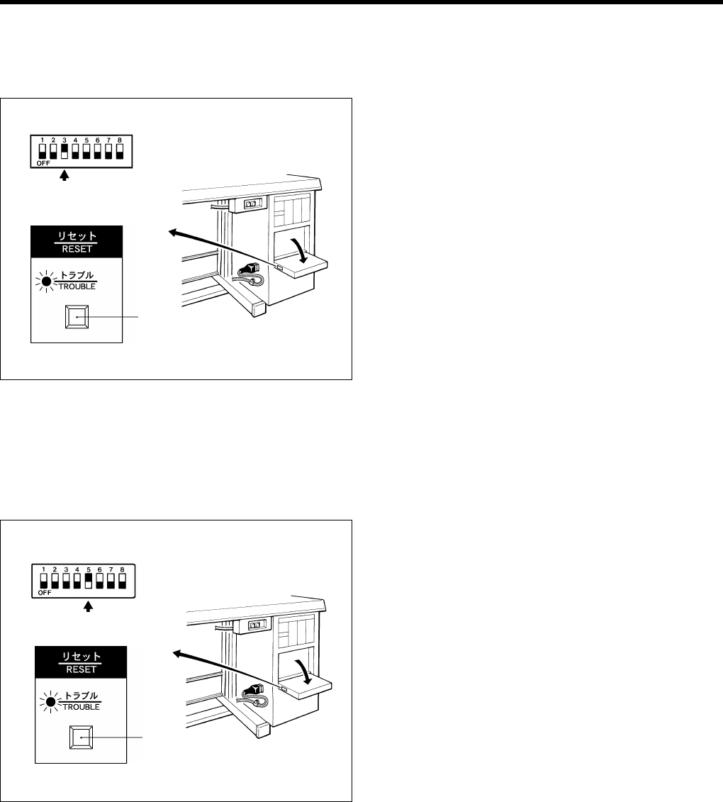
7. SEWING
RH-9800 37
7-7. Setting the feed bracket to the front position
Setting the material will be easier if the feed bracket is moved forward from the standard cloth setting position.
* Cycle time will be reduced with this setting, particularly if cutting after sewing is selected.
1. Turn off the power.
2. Set DIP switch No. 3 inside the front panel.
3. Turn on the power.
4. Press the RESET button (1).
5. The feed bracket will move to the front position.
6. Sewing can then be carried out as normal. (Refer to
page 30.)
7-8. Switching between single-pedal and dual-pedal operation
(Switching the foot controller)
The cloth presser can be lowered and the machine can start sewing just by pressing the start switch, without having to
use the cloth presser switch.
1. Turn off the power.
2. Change the setting of DIP switch No.5.
OFF: To use both pedals (cloth presser switch and
start switch)
ON: To use only one pedal (start switch)
3. Turn on the power and press the RESET button (1).
Sewing can then be carried out as normal.
Note: During single pedal operation, when the start
switch is pressed, the cloth presser is lowered
and sewing starts straight away.
1178Q
1179Q 1180Q
(1)
1179Q 1180Q
(1)
1181Q
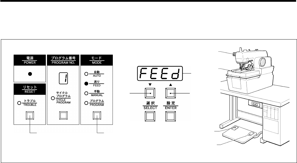
7. SEWING
RH-9800
38
7-9. Using feed mode
In this mode, the feed bracket and the cloth presser can be moved while the needle is stopped.
It is useful for checking the relative positions of the throat plate and the cloth presser.
1. Press the MODE button (1) to switch to feed mode.
* "FEEd" will appear in the front panel display (J).
2. Press the cloth presser switch (2). The cloth pressers will be lowered.
3. Press the start switch (3).
The feed bracket (4) will move to the sewing start position.
* When the start switch (3) or the "Up" button (L) is pressed, the feed bracket (4) will move to the next sewing
position.
* If the "Down" button (K) is pressed, the feed bracket (4) will move to the previous sewing position.
* To return the feed bracket (4) to the cloth setting position while sewing:
1) Press the EMERGENCY STOP switch (5).
2) Press the RESET button (6).
Note: The knife will not operate during this time.
1184Q
1183Q
1182Q
(6) (1)
(K) (L)
(J)
(5)
(4)
(2)
(3)
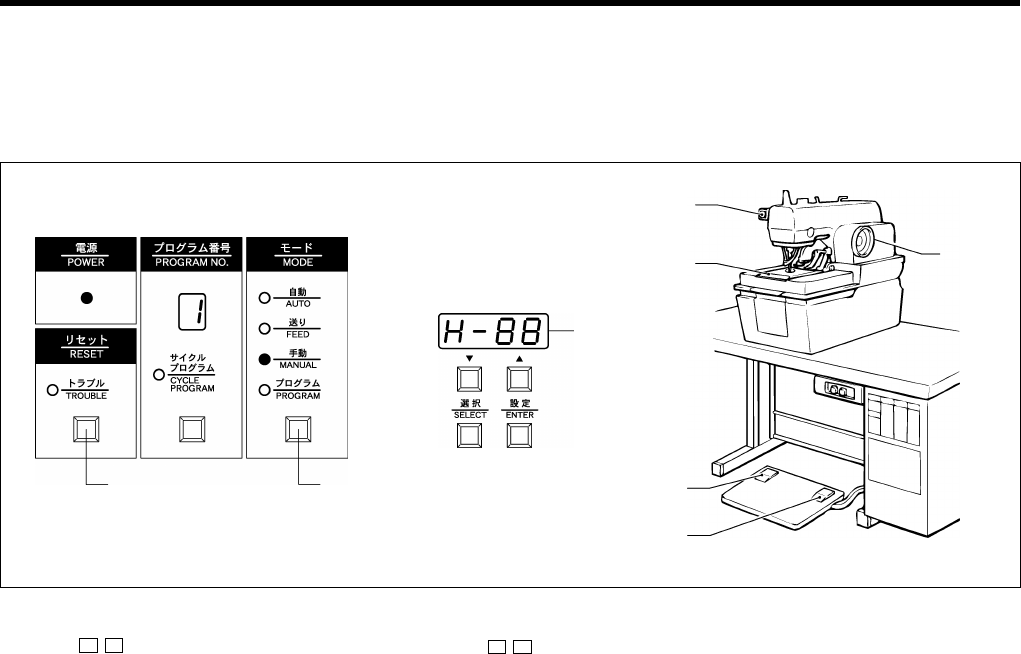
7. SEWING
RH-9800 39
7-10. Using manual mode
In this mode, the needle and the feed bracket can be moved one stitch at a time by turning the upper shaft pulley by
hand.
It is useful for checking the positions of the needle and the looper after the looper timing has been adjusted.
1. Press the MODE button (1) to switch to manual mode.
* “H- ” will appear in the front panel display (J). ( represents the number of stitches remaining.)
2. Press the cloth presser switch (2). The cloth presser will be lowered.
3. Press the start switch (3).
* The knife will operate only when cutting before sewing has been set.
* The feed bracket (4) will move to the sewing start position.
4. Turn the upper shaft pulley (5) toward you.
The feed bracket (4) will move to the next sewing position in accordance with the rotation of the upper shaft.
Note: If the upper shaft pulley (5) is turned in the wrong derection, the feed bracket timing may become disrupted.
* To return the feed bracket (4) to the cloth setting position while sewing:
1) Press the EMERGENCY STOP switch (6).
2) Press the RESET button (7). The feed bracket (4) will then return to the cloth setting position.
5. Turn the upper shaft pulley (5) until the last stitch has been sewn. The buzzer will then sound.
Note: Check that the mark on the upper shaft pulley (5) is aligned with the notch in the pulley cover.
6. Press the start switch (3).
* The movement of the feed bracket (4), lower thread trimming and opration of the cloth presser will all be carried out
as a single step.
* The knife will operate only when cutting after sewing has been selected.
0783Q
(1)(7)
(J)
0784Q 0785Q
(6)
(4)
(2)
(3)
(5)
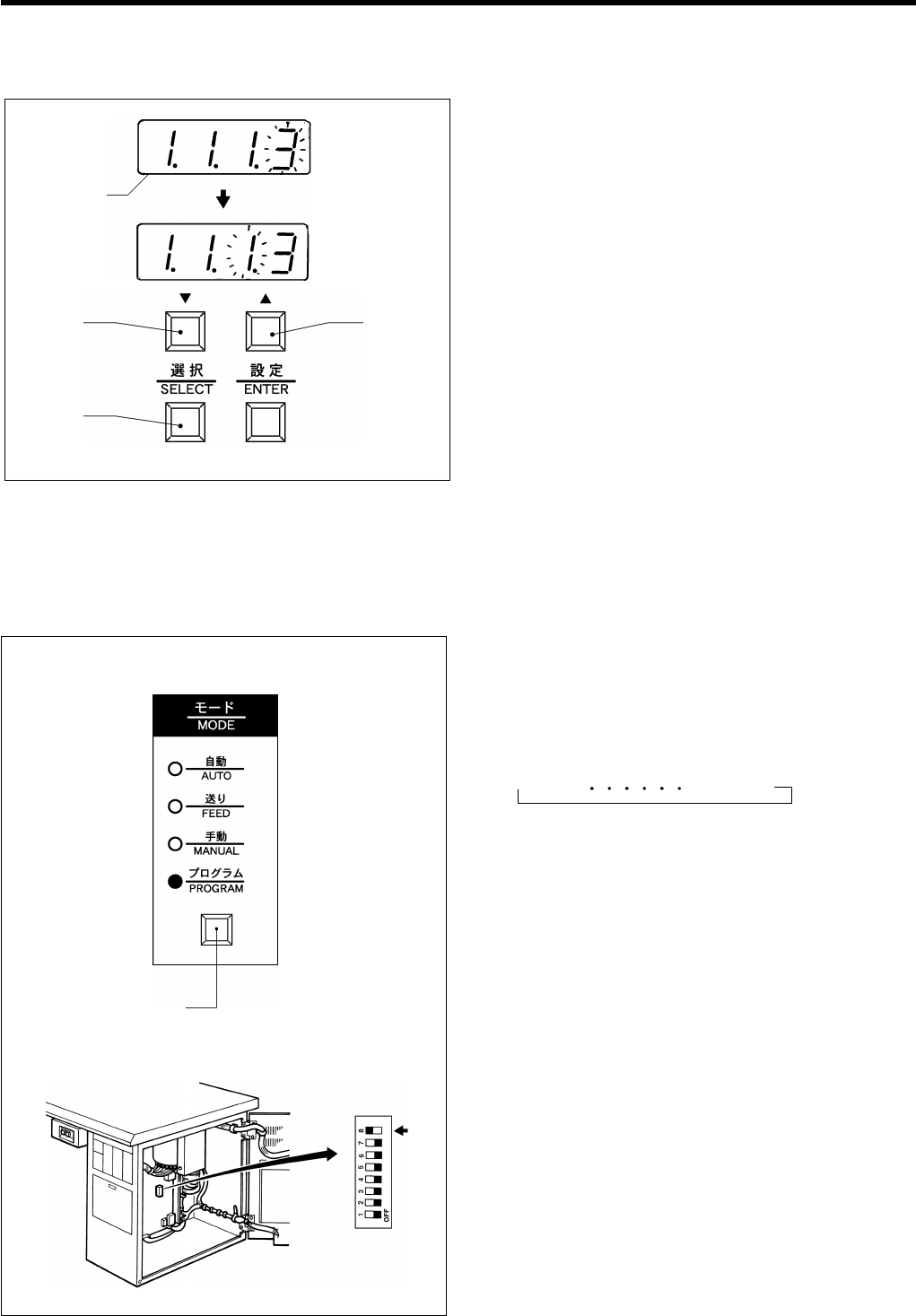
7. SEWING
RH-9800
40
7-11. Changing the cycle program counter
The cycle program counter can be easily changed if necessary, for instance because re-sewing was necessary.
1. If carrying out cycle sewing in AUTO mode, switch the
contents shown in the front panel display from the
production counter to the cycle program.
The program number which is to be sewn next will
flash in the display. To change the cycle program
counter (the position where the display is flashing),
press the "up" button (L) or the "down" button (K) to
make the desired setting.
* If you would like to switch the display from the cycle
program to the production counter, press the
SELECT button (M). The production counter will be
displayed while this switch is being pressed.
7-12. Setting the number of home position cycles
The number of home position cycles can be set in order to shorten the overall cycle time.
* This function is only valid when DIP switch No. 8 on the circuit board is set to ON.
1. Press the MODE button (1) to switch to program
mode.
2. Press the SELECT button (M) so that "HP" is
displayed in the front panel display.
* The display will change in the following order each
time the SELECT button is pressed:
→A → B P4 → HP
(Continued on next page)
1186Q
1185Q
(L)(K)
(M)
(J)
(1)
1188Q
1187Q
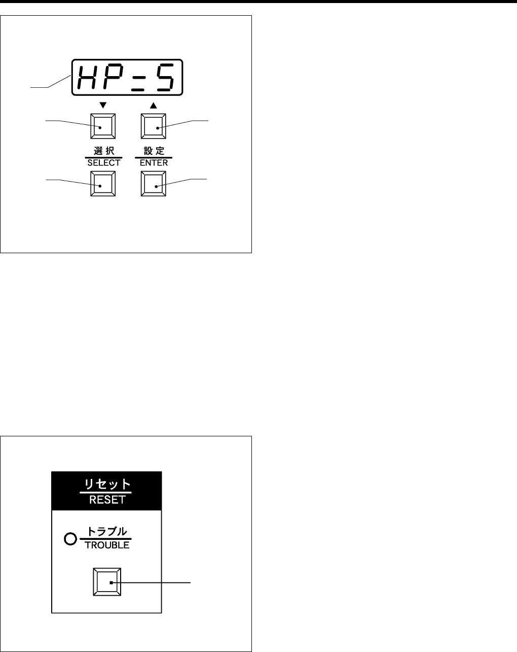
7. SEWING
RH-9800 41
3. Press the "up" button (L) or the "down" button (K) until
the desired number of home position cycles is
displayed.
The setting range is between 0 and 9.
* If the number of home position cycles is set to "5",
returning to the home position will occur once for
every five cycles.
However, when carrying out cycle sewing, the
machine will return to the home position once for
each cycle program regardless of the number of
home position cycles which have been set (unless
the setting is "0").
Normal home position cycling will not be carried out
if the setting is "0".
4. Press the ENTER button (N) to accept the home
position cycle setting. This setting will apply to all
program numbers from 1 to 9.
* The display will stop flashing and will start
illuminating steadily.
Note: If for some reason an excessive load is applied to the feed bracket which causes it to slip, then there is the
danger that this will have an adverse effect on subsequent sewing operations. Therefore, it is recommended that
you return to the home position for each cycle (i.e. that you leave DIP switch No. 8 on the circuit board set to
OFF).
7-13. Returning to the home position
This is useful for correction purposes when mistiming occurs in the home position cycle because re-sewing was carried
out.
* This function is only valid when DIP switch No. 8 on the circuit board is set to ON.
1. When at the home position in AUTO mode, press the
RESET button (1) to start sewing from the home
position.
(J)
(K)
(M)
(L)
(N)
1171Q
(1)
1189Q
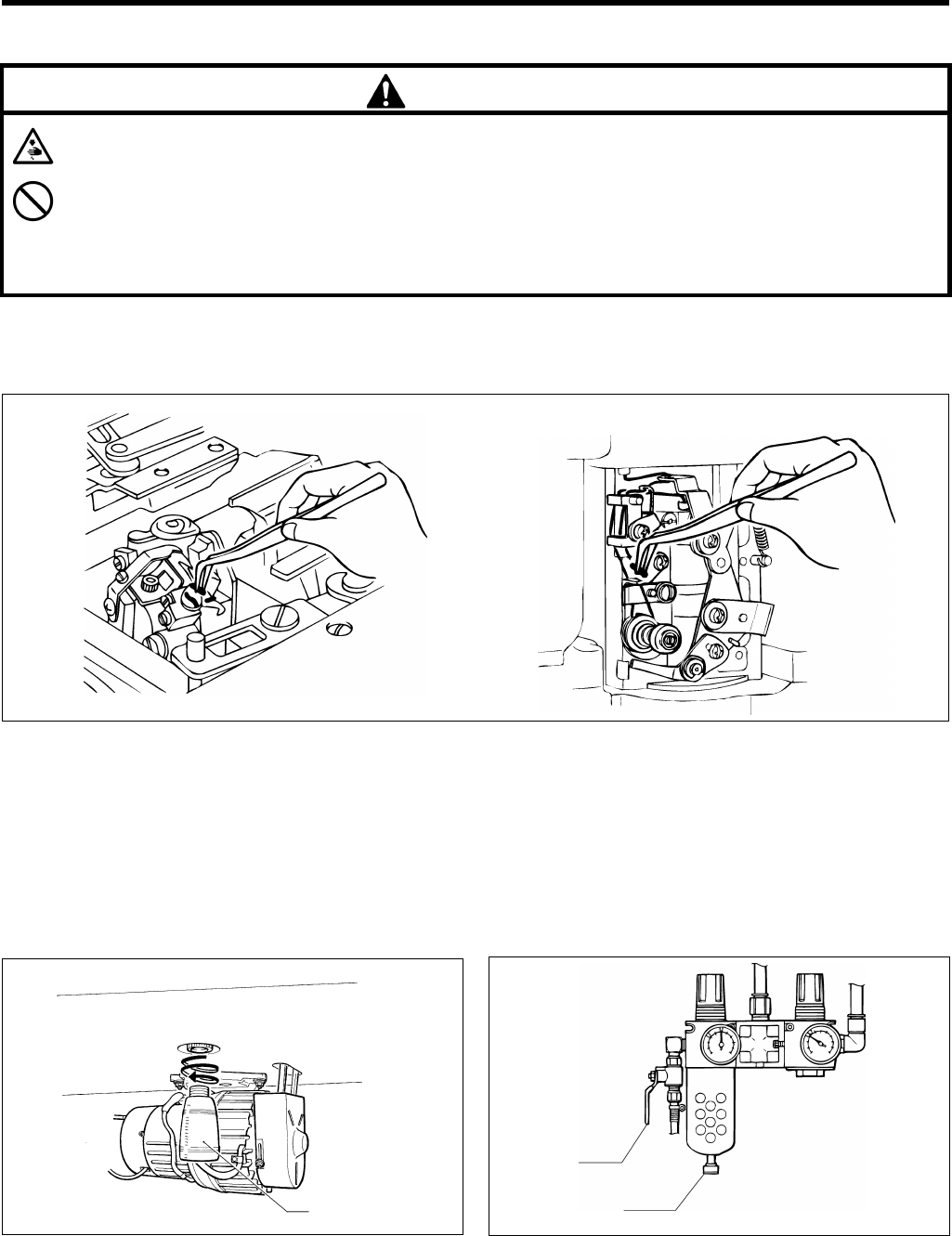
8. CLEANING AND MAINTENANCE
RH-9800
42
8. CLEANING AND MAINTENANCE
CAUTION
Turn off the power switch before starting any cleaning work, otherwise the machine may operate if the start
switch is pressed by mistake, which could result in injury.
Be sure to wear protective goggles and gloves when handling the lubricating oil and grease, so that they do not
get into your eyes or onto your skin, otherwise inflammation can result.
Furthermore, do not drink the oil or eat the grease under any circumstances, as they can cause vomiting and
diarrhoea.
Keep the oil out of the reach of children.
8-1. Cleaning
If using an air gun, do not use it while the machine head is tilted back, otherwise oil and thread scraps may adhere to the
cutter sensor and timing belt, resulting in operating problems.
1. Turn off the power.
2. Turn the air cock to stop the air.
* Turn the knob to release the air.
3. Remove any thread scraps and dust, etc. from the thread paths for the needle thread, looper thread and gimp.
In particular, the looper thread path should be cleaned every day to keep it free from thread scraps and dust.
4. Check the oil level by looking at the sight glass. If the oil level is low, replenish the oil supply.
5. Remove and discard any oil that has collected in the oil container.
6. Check the air filter and remove any water that has collected in the drain.
(Refer to the illustration below.)
8-2. Draining the oil 8-3. Checking the air filter
1190Q
(1) 0946Q
(1)
(2)
0849Q
0848Q
1. When the oil container (1) is full of oil, remove the oil
container (1) and let the oil drain out.
Note: Clean up any oil that may have been spilt onto
the floor.
1. Close the air cock (1).
2. Turn the screw (2) to release any air and water in the
drain.
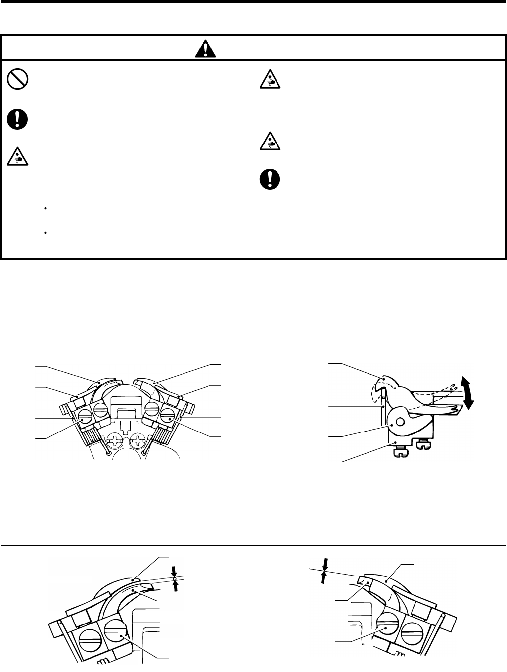
9. STANDARD ADJUSTMENTS
RH-9800 43
9. STANDARD ADJUSTMENTS
CAUTION
Maintenance and inspection of the sewing
machine should only be carried out by a qualified
technician.
Ask your Brother dealer or a qualified electrician to
carry out any maintenance and inspection of the
electrical system.
Turn off the power switch and disconnect the
power cord from the wall outlet at the following
times, otherwise the machine may operate if the
start switch is pressed by mistake, which could
result in injury.
When carrying out inspection, adjustment and
maintenance.
When replacing consumable parts such as the
loopers and knife.
Disconnect the air hoses from the air supply and
wait for the needle on the pressure gauge to drop
to "0" before carrying out inspection, adjustment
and repair of any parts which use the pneumatic
equipment.
If the power switch and air need to be left on when
carrying out some adjustment, be extremely
careful to observe all safety precautions.
If any safety devices have been removed, be
absolutely sure to re-install them to their original
positions and check that they operate correctly
before using the machine.
9-1. Adjusting the height of the spreader and looper
Spreader height
The clearance between the left spreader (forked spreader) and the left looper must be set to match the thickness of the
lower thread. The clearance between the right spreader and the right looper should be as small as possible while still
letting the parts slide.
1. The right spreader (1) and left spreader (2) move by means of springs (3). Adjust so that the spreaders move smoothly
between the right spreader stopper (4), the left spreader stopper (5) and the LS-holder bracket (6), with no looseness.
2. If adjustment is necessary, loosen the screw (7) and then move the right spreader stopper (4) or left spreader stopper
(5) up or down.
Looper height
1. Set the clearance between the left looper (8) and the left spreader (2) to the same distance as the thickness of the
lower (looper) thread.
2. The clearance between the right looper (9) and the right spreader (1) should be as small as possible.
3. If adjustment is necessary, loosen the screw (10) and then move the left looper (8) and right looper (9) up or down.
(2) (1)
(4)
(7)
(3)
(5)
(3)
(7)
(2)
(3)
(5)
(6) 0948Q
0947Q
(2)
(8)
(10)
(1)
(9)
(10)
0949Q 0950Q
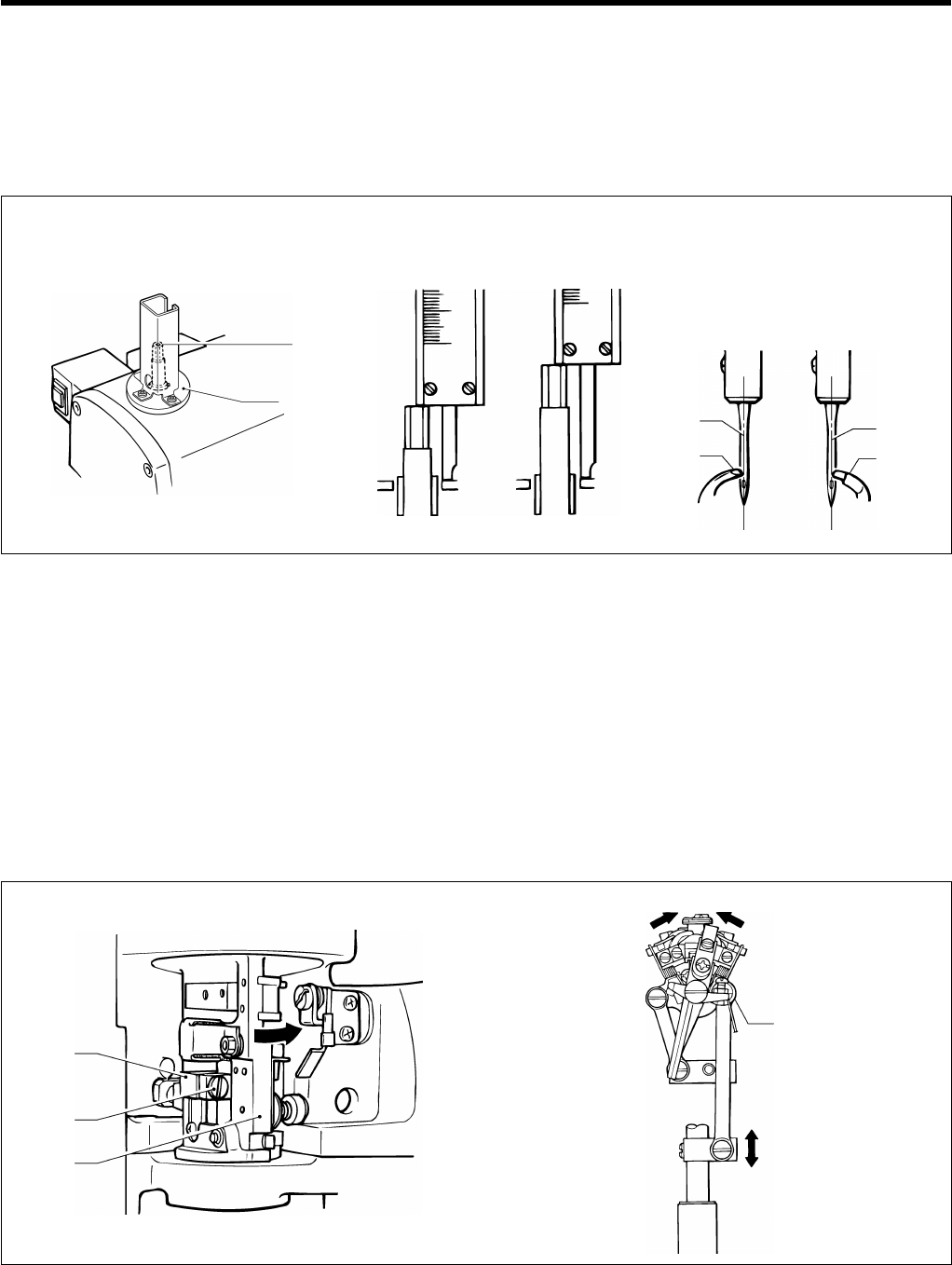
9. STANDARD ADJUSTMENTS
RH-9800
44
9-2. Adjusting the needle and looper timing
The distance by which the needle bar rises from its lowest position to the position where the tip of the left looper and the
center of the needle are aligned should be the same as the distance from its lowest position to the position where the tip
of the right looper and the center of the needle are aligned.
Before adjusting the looper timing, first adjust the stitch width (needle racking width).
* Refer to "Adjusting the needle racking width (stitch width)" on page 48. The standard width is 3 mm.
1. Move the needle bar to its lowest position.
2. Use calipers to measure the distance between the end of the needle bar (1) and the top of the needle bar bracket (2)
when the needle bar is at its lowest position.
3. Turn the upper shaft pulley until the tip of the left looper (4) and the center of the needle (3) are aligned when the
needle (3) is at the inside sewing position, and then use the calipers to take the same measurement as taken in step 2.
Find the difference between the measurements taken in this step and in step 2.
4. Follow the same procedure as in step 3. above to find the difference between the two measurements when the needle
(3) is at the outside sewing position.
* When the needle (3) is at the inside sewing position, the tip of the left looper (4) should be aligned with the center of
the needle (3), and when the needle (3) is at the outside sewing position, the tip of the right looper (5) should be
aligned with the center of the needle (3).
* The distance from the end of the needle bar (1) and the top of the needle bar bracket (2) should be the same when
the needle (3) is at both the inside sewing position and the outside sewing position.
5. If adjustment is necessary, turn the race stand (6) in the direction indicated by the arrow in the illustration, loosen the
screw (7), and then move the looper link support (8) up or down to tilt the LS-holder bracket (9) to the left or right (in the
direction of the arrow).
Lowest position
of needle bar
(1)
(2) (3)
(4)
(3)
(5)
0951Q 0952Q 0953Q
(9)
(8)
(7)
(6)
0955Q
0954Q
When center of needle
and looper tip are aligned
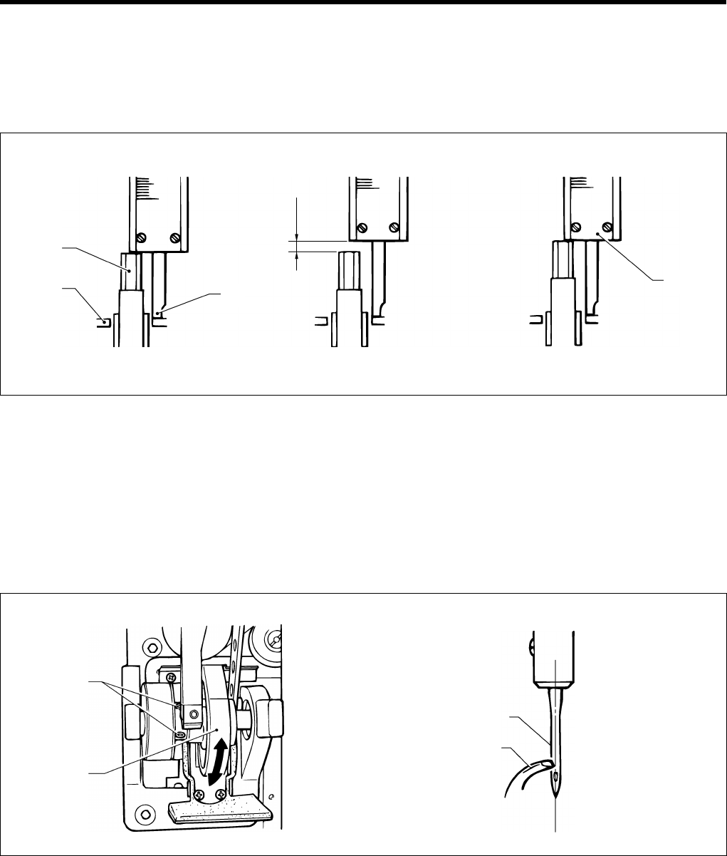
9. STANDARD ADJUSTMENTS
RH-9800 45
9-3. Adjusting the loop stroke
The loop stroke is the distance the needle bar rises from its lowest position to the position where the tips of the left and
right loopers are aligned with the center of the needle. The standard loop stroke is 2.7 mm. (The loop stroke may need
changing depending on the material and thread being used.)
* Carry out the adjustment in "9-2. Adjusting the needle and looper timing" before making this adjustment.
1. In the same way as in "9-2. Adjusting the needle and looper timing", move the needle bar to its lowest position with the
needle at the inside sewing position, and then use calipers to measure the distance between the end of the needle bar
(1) and the top of the needle bar bracket (2).
2. Add 2.7 mm to the value obtained in step 1. above.
3. Touch the end of the calipers (A) against the top of needle bar bracket (2), and then turn the upper shaft pulley until the
end of the needle bar (1) touches the edge of the calipers (B). Check that the tip of the left looper is aligned with the
center of the needle at this time.
4. In the same way, check that the tip of the right looper is aligned with the center of the needle when the needle is at the
outside sewing position.
5. If the tips of the loopers are not aligned with the center of the needle, carry out the adjustment below.
Raise the machine head.
Loosen the two screws (3) of the lower shaft timing pulley, hold the upper shaft pulley so that it doesn't move, and then
turn the lower shaft cam (4) in the direction indicated by the arrow until the tip of the left looper (5) is aligned with the
center of the needle (6). Once they are aligned, tighten the two screws (3).
After adjusting, check that the screws have been adequately tightened.
Once this adjustment has been carried out, repeat the procedure given in "9-2. Adjusting the needle and looper
timing".
2.7 mm
(1)
(2) (B)
0956Q
(A)
(3)
(4)
(6)
(5)
0957Q 0958Q
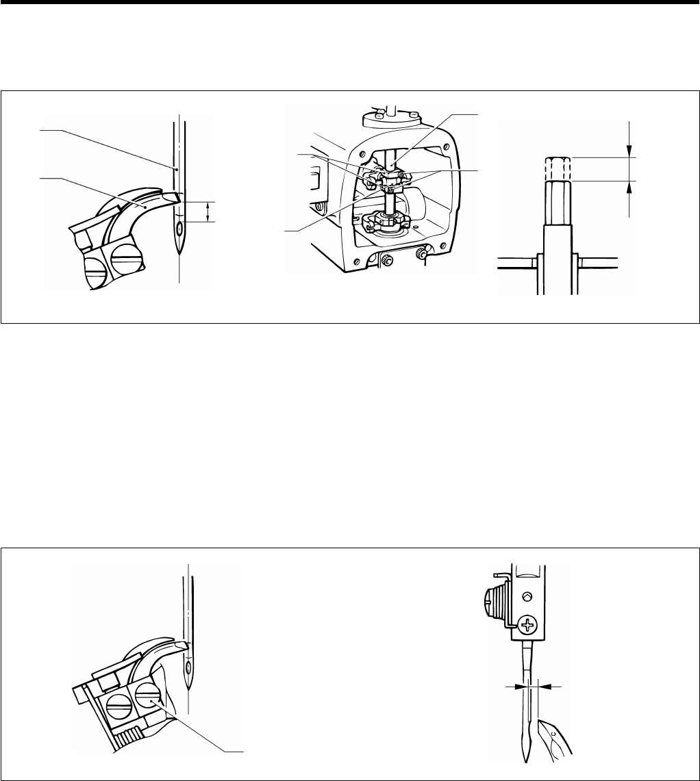
9. STANDARD ADJUSTMENTS
RH-9800
46
9-4. Adjusting the height of the needle bar
The standard height for the needle bar is 2.5 mm. (The needle bar height may need changing depending on the material
and thread being used.)
1. Align the tip of the left looper (1) with the center of the needle (2) when the needle (2) is at the inside sewing position.
2. Remove the face plate.
3. Loosen the screw (3) of the needle bar clamp (5) and adjust the height of the needle bar (4).
* After aligning the tip of the left looper (1) with the top edge of the needle hole, lower the needle bar (4) 2.5 mm.
4. Adjust so that there is as little play as possible, and so that the needle bar clamp (5) and the needle bar horizontal link
(6) can maintain their oil films. This will help to ensure that the needle bar turns smoothly.
9-5. Adjusting the clearance between the looper and needle
Be sure to carry out this adjustment after changing the size of the needle.
The clearance between the tip of the looper and the needle should be 0.05 - 0.2 mm.
1. Loosen the looper screw (1) and then adjust the clearance.
* This clearance must be uniform while the race stand is rotating (through 360o ).
If the clearance is not uniform, adjust the turning center for the needle bar. (This adjustment is made at the time of
shipment from the factory.)
* After making the adjustment in step 1. above, carry out the adjustment procedure given in "9-7. Adjusting the
spreader mounting positions".
2.5 mm
2.5 mm
(2)
(1)
(4)
(5) (3)
0959Q 0960Q 0961Q
(6)
0.05 - 0.2 mm
(1)
0963Q
0962Q
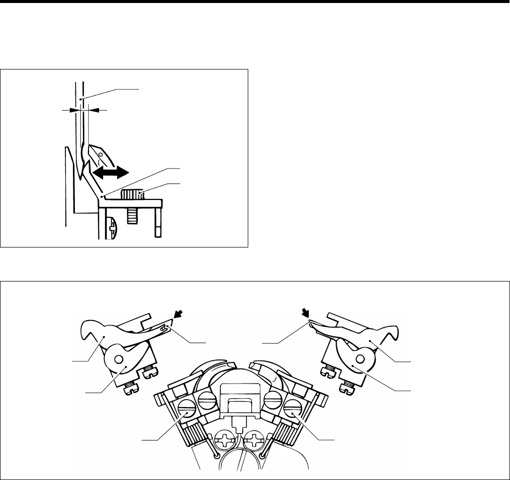
9. STANDARD ADJUSTMENTS
RH-9800 47
9-6. Adjusting the needle guard
Be sure to carry out this adjustment after changing the size of the needle.
The needle must remain stationary with respect to the needle guard until the tip of the looper reaches the needle.
1. Loosen the screw (1) and then move the needle guard
(3) in the directions indicated by the arrows by an
appropriate amount in accordance with the thickness
of the needle (2).
Note: Adjust so that the looper clasps the upper
thread securely.
9-7. Adjusting the spreader mounting positions
1. Loosen the screw (3) and adjust the position of the left spreader stopper (4) so that the fork of the left spreader (1) is
aligned with the lower thread guide hole of the left looper (2).
2. Loosen the screw (7) and adjust the position of the right spreader stopper (8) so that the tip of the right spreader (5) is
aligned with the tip of the right looper (6).
Note: Both the left spreader (1) and right spreader (5) should be installed so that they do not project past the tips of
the left looper (2) and right looper (6) respectively.
(2)
(3)
(1)
0964Q
(1)
(4)
(3) (7)
(5)
(8)
(6)
(2)
0965Q
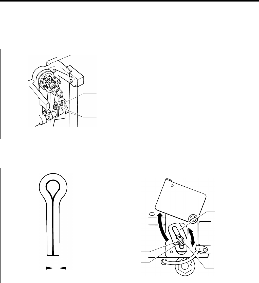
9. STANDARD ADJUSTMENTS
RH-9800
48
9-8. Adjusting the spreader timing
When the needle is at the inside sewing position, the left spreader should touch the left spreader stopper and stop
immediately before the needle bar reaches its lowest position.
When the needle is at the outside sewing position, the right stopper should touch the right spreader stopper and stop
immediately before the needle bar reaches its lowest position.
1. Raise the machine head.
2. Loosen the screw (1) and the nut (2), and then turn the
adjusting screw (3) to adjust the spreader timing.
3. After adjusting, tighten the nut (2) and the screw (1).
9-9. Adjusting the needle racking width (stitch width)
The needle racking width is set to 3 mm at the time of shipment from the factory.
1. Loosen the needle racking adjustment nut (1) and then adjust the needle racking width by sliding the adjustment screw
(2) vertically along the oval slot.
The stitch width becomes smaller as the adjustment screw (2) is moved upward.
Note: If the needle racking width is changed greatly, you should re-adjust the timing between the needle and the
loopers.
(Refer to "9-2. Adjusting the needle and looper timing".)
(2)
(3)
(1)
0966Q
Becomes smaller
Becomes larger
2 mm
3 mm
(2)
(1)
0967Q 0968Q
Neddle racking width 1.5 - 3.2 mm
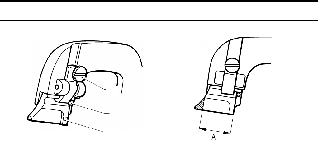
9. STANDARD ADJUSTMENTS
RH-9800 49
9-10.
Changing the knife cutting length (Replacing the cutting block)
1. Grind or replace the cutting block after changing the knife cutting length.
* When replacing the cutting block with a new one, be sure to adjust the contact between the knife and the cutting
block. (Refer to the next page.)
2. Loosen the screw (1), and then remove the cutting block (2).
Because the knife cutting length is set in accordance with the length of the cutting block, grind the cutting block as
shown in (A ) in the above illustration.
Cutting block length A = Knife cutting length + 1.5 mm
3. When installing the cutting block, push in the pin (3) and then tighten the screw (1).
* Do not use knives with different numbers on the same cutting block. If knives with different numbers are used,
accurate cutting will not be possible and the knife will be damaged.
Changing in the cutting block operation time.
If cutting is not possible even when the air pressure is increased to 0.3 MPa, memory switch No. 18 can be used to
increase the cutting block ON time. (Refer to “6-6. Using the memory switch”.)
(1)
(3)
(2)
0969Q 0970Q
Illustration (A)
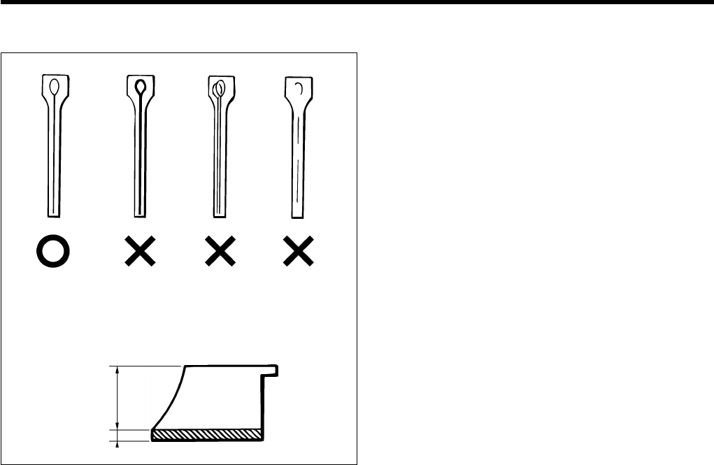
9. STANDARD ADJUSTMENTS
RH-9800
50
9-11.
Adjusting the contact between the knife and the cutting block
1. Remove the cutting block. (Refer to the previous
page.)
2. If the knife incision on the surface of the cutting block
is very deep, if there are two or more incisions on the
cutting block because different knives were used, or if
only part of the incision has been made, grind the
surface of the cutting block smoothly until a single
knife incision can still be seen faintly.
3. The cutting pressure over the whole of the cutting
block should be uniform so that the material will be cut
cleanly.
Grind the surface of the cutting block so that the knife
incision will be uniform over the whole of the cutting
block.
* The cutting block can be filed until its height is 19
mm.
4. If the material cannot be cut cleanly even though
the cutting block has been ground correctly,
check whether the tip of the knife is worn.
* If the tip is worn, replace the knife.
Do not use the old cutting block after the knife has
been replaced, otherwise it may damage the tip of
the knife.
Adjusting the contact between the knife and the cutting block
To see the knife incision more easily, color the cutting surface of the cutting block with a marker pen.
1. Operate the cutting block three times with the knife making a mark on it each time.
2. Adjust the position of the cutting block or contact between the knife and the cutting block until the knife consistently
makes a mark in the same place.
Filing the cutting surface of the cutting block
Use a flat file for filing.
1. Filing the cutting surface of the cutting block on which the knife incision breaks off or is shifted
1-1. Grip the cutting block in a vise.
1-2. File the surface of the cutting block smoothly until the knife incision is eraced away.
2. Filing the cutting surface of the cutting block in which knife incision is deep
2-1. Grip the cutting block in a vise.
2-2. File the surface of the cutting block smoothy until a single knife incision can still be seen faintly.
19 mm
3 mm
1. Knife incision
is correct
0971Q
0972Q
2. Knife incision
is too deep
3. Two knife
incisions
4. Partial knife
incision
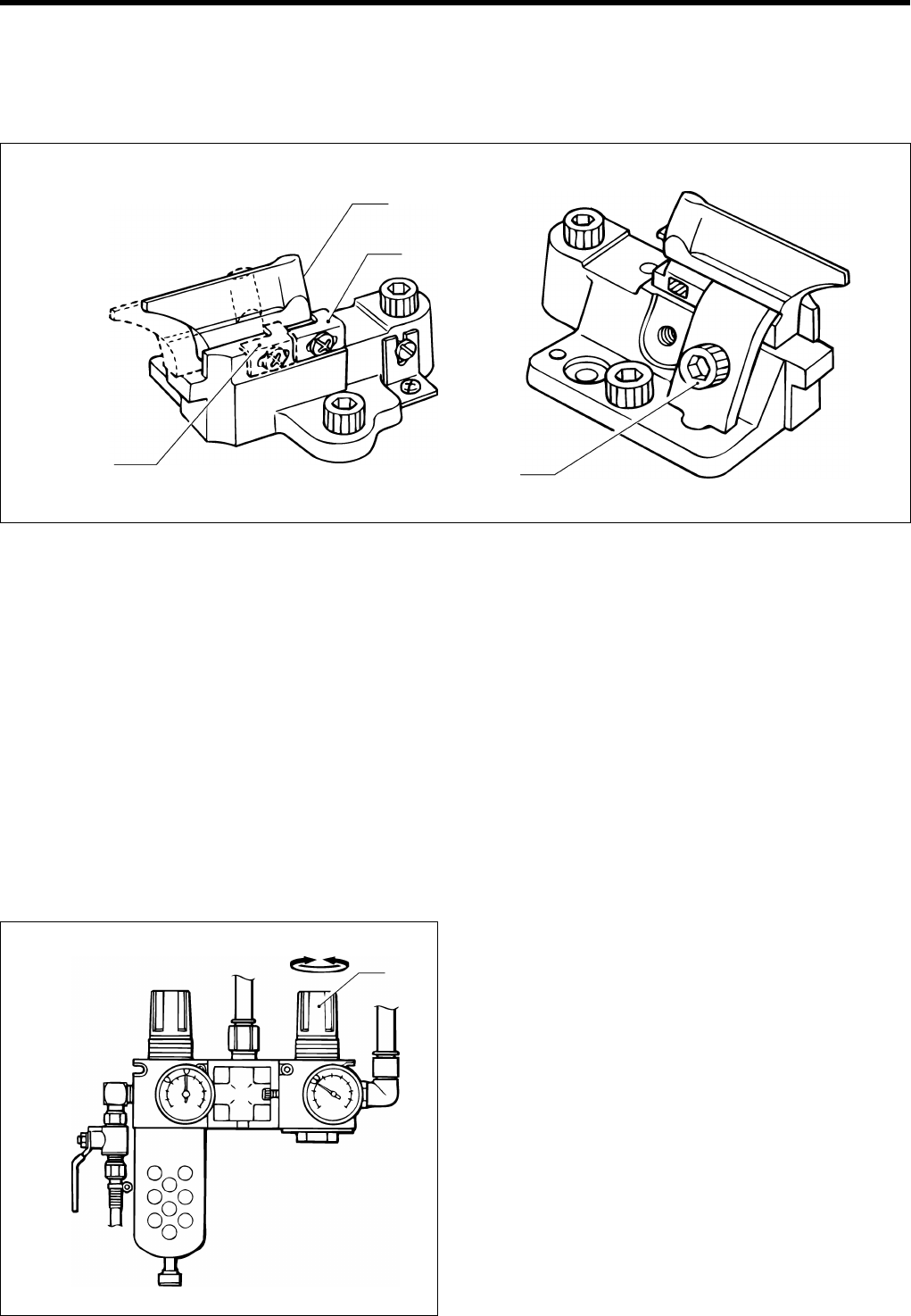
9. STANDARD ADJUSTMENTS
RH-9800 51
9-12. Replacing the knife
When replacing the knife with a new one, file the surface of the cutting block until smooth and until the knife does not
leave a mark on the cutting block.
Before replacing the knife, be sure to check that there is no gap between the knife (1) and the knife stopper (2).
1. Loosen the screw (3), and then remove the knife (1).
2. Insert the new knife (1) into the knife stopper (2), and then tighten it with the screw (3).
3. Adjusting the contact between the knife and cutting block. (Refer to the previous page.)
Note: For L1 - L4 specifications, secure the knife stopper (2) in the position closest to you (the position indicated by the
dotted lines).
* When replacing the knife (1), make sure that the knife number matches the number for the eyelet shape.
Replace the knife and cutting block as a set.
If knives with different numbers are used on the same cutting block, accurate cutting will not be possible, and damage
to the knife may result.
9-13. Adjusting the cutting pressure
Adjust the cutting pressure to the minimum pressure that still allows the material to be cut.
* If the knife cutting length is 20 mm, sufficient cutting performance can be obtained with an air pressure of 0.2 MPa.
To adjust the cutting pressure, adjust the air pressure of the knife pressure adjustment regulator (1) which is mounted
underneath the work table.
* If the cutting pressure is increased to more than is
necessary, it will cause the cutting block to become
worn or the knife to become damaged.
* If the material cannot be cut cleanly, do not increase
the cutting pressure over the maximum limit. Check
the contact between the knife and the cutting block,
while referring to "9-11. Adjusting the contact between
the knife and the cutting block".
(L 1 - L 4)
(1)
(2)
(3)
0973Q 0974Q
0975Q
(1)
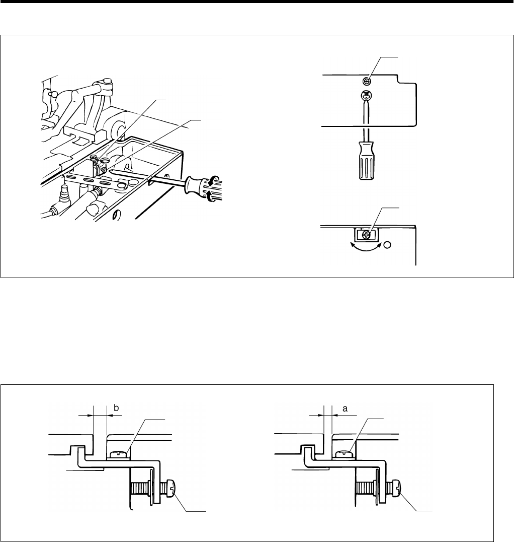
9. STANDARD ADJUSTMENTS
RH-9800
52
9-14. Adjusting the cloth opening amount
1. Loosen the screw (1), and then insert a screwdriver into the notch in the side of the feed bracket and turn the adjusting
screw (2) to adjust the opening amount.
2. After tightening the screw (1), measure the opening amount.
Note: Adjust so that the opening amounts for the left and right cloth presser plates are equal.
* It is usually sufficient for one cloth presser plate to open by 0.8 mm.
Measuring the opening amount
1. Switch the mode to feed mode. (Refer to page 20.)
2. Lower the cloth presser and then use calipers to measure the distance a.
3. Press the start switch. The feed bracket will move and then the left and right cloth presser plates will open.
4. Use calipers to measure the distance b.
5. The difference between a and b is the opening amount. (Opening amount = a - b)
(1)
(2)
(1)
(2)
0976Q 0977Q
(1)
(2)
(1)
(2)
0978Q 0979Q
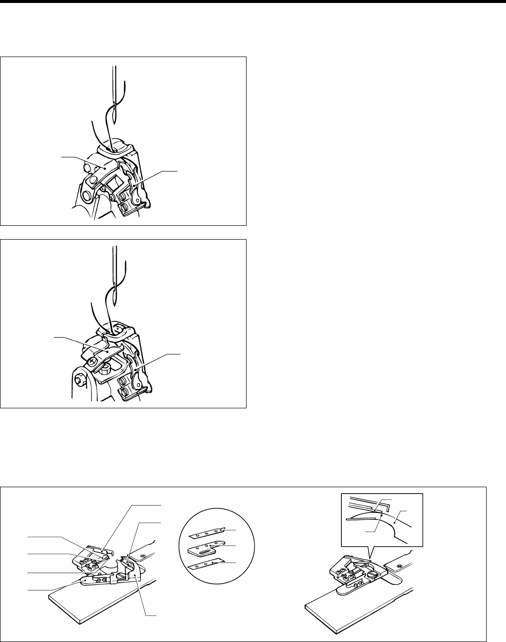
9. STANDARD ADJUSTMENTS
RH-9800 53
9-15. Adjusting the trimming of the upper thread
The upper thread should be trimmed at the correct time after sewing is completed.
<-00, -01>
1. Adjust so that the upper thread trimmer knife (1) cuts
only one of the threads in front of the right looper (2).
Note: If both strands of the thread loop are cut, the
thread remaining in the needle may become
too short and skipped stitches may result.
<-02>
1. Adjust so that the upper thread trimmer knife (3) cut
only one of the threads in front of the right looper (4).
Note: If both strands of the thread loop (forward and
back) are cut, the thread remaining in the
needle may become too short and skipped
stitches may result.
9-16. Adjusting the trimming of the lower thread and gimp
<-00, -01>
The lower thread and gimp should be trimmed at the correct time after the feed bracket has returned to the home position.
Thread trimming operation can be checked in steps while manual mode is active. (Refer to “Using manual mode” on page 39.)
1. The mechanism is adjusted so that the lower thread and gimp are separated from each other and spread by the loop
spreader (1).
2. The lower thread is held between thread nipper M (2) and thread nipper D (3) on the plate spring.
The gimp is held between thread nipper M (2) and thread nipper U (4) on the plate spring.
3. Adjust so that the edge of the fixed knife (6) and the index mark (8) on the movable knife (7) are aligned when the
thread trimmer knife arm (5) is at the maximum stroke.
(2)
(1)
(3)
(4)
0980Q
0981Q
(6)
(1)
(7)
(4)
(2)
(3)
(7)
0983Q
0982Q
(5)
(4)
(2)
(3)
(6)
(8)
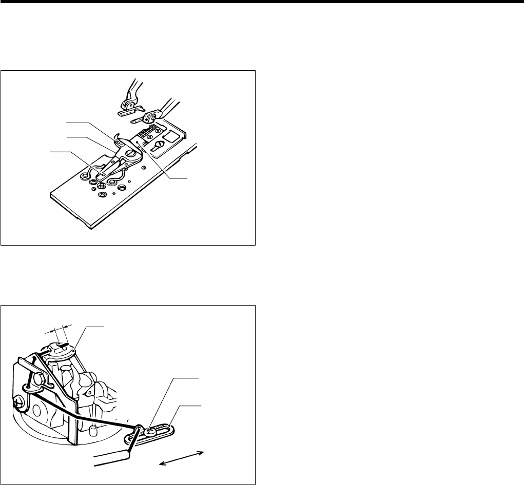
9. STANDARD ADJUSTMENTS
RH-9800
54
<-02>
The lower thread and gimp should be trimmed at the correct time after the cloth pressers rise at the feed home position.
Thread trimming operation can be checked in steps while manual mode is active. (Refer to “Using manual mode” on
page 39.)
1. The mechanism is adjusted so that the lower thread
and gimp are spread by the thread handler (1).
2. The movable knife driving cam (2) operates, and the
right movable knife (3) and left movable knife (4) mesh
and the thread is cut.
9-17. Adjusting the gimp length after trimming (-02)
Adjust so that approximately 4 mm of the gimp thread is
coming out from the throat plate (1).
1. Loosen the screw (2) and move the gimp thread guide
J (3) in the direction of the arrow to adjust the length.
(3)
(2) (4)
(1)
0984Q
Becomes longer
Becomes shorter
(2)
(3)
Approx. 4 mm (1)
0985Q
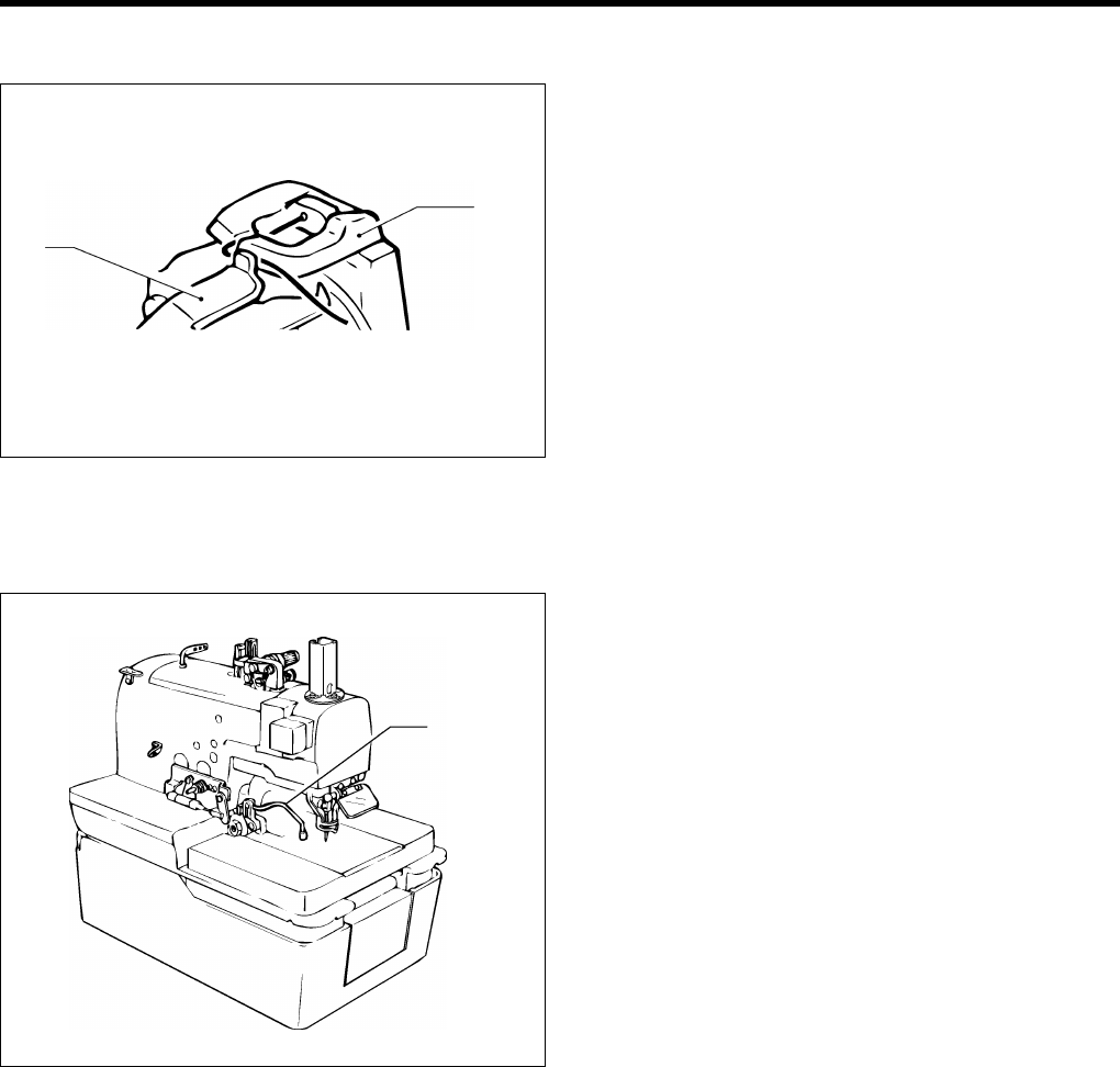
9. STANDARD ADJUSTMENTS
RH-9800 55
9-18. Lower thread presser (-02)
The lower thread presser (1) operates at the same time
as upper thread trimming is carried out.
The end of the lower thread is securely held between the
lower thread presser (1) and the throat plate (2).
9-19. Sub presser (-02)
Trimming of the lower thread and gimp is carried out
when the cloth pressers rise. The sub presser (1) endures
that the material does not move during thread trimming, in
order to maintain a stable thread length after trimming.
(2)
(1)
0986Q
(1)
0987Q
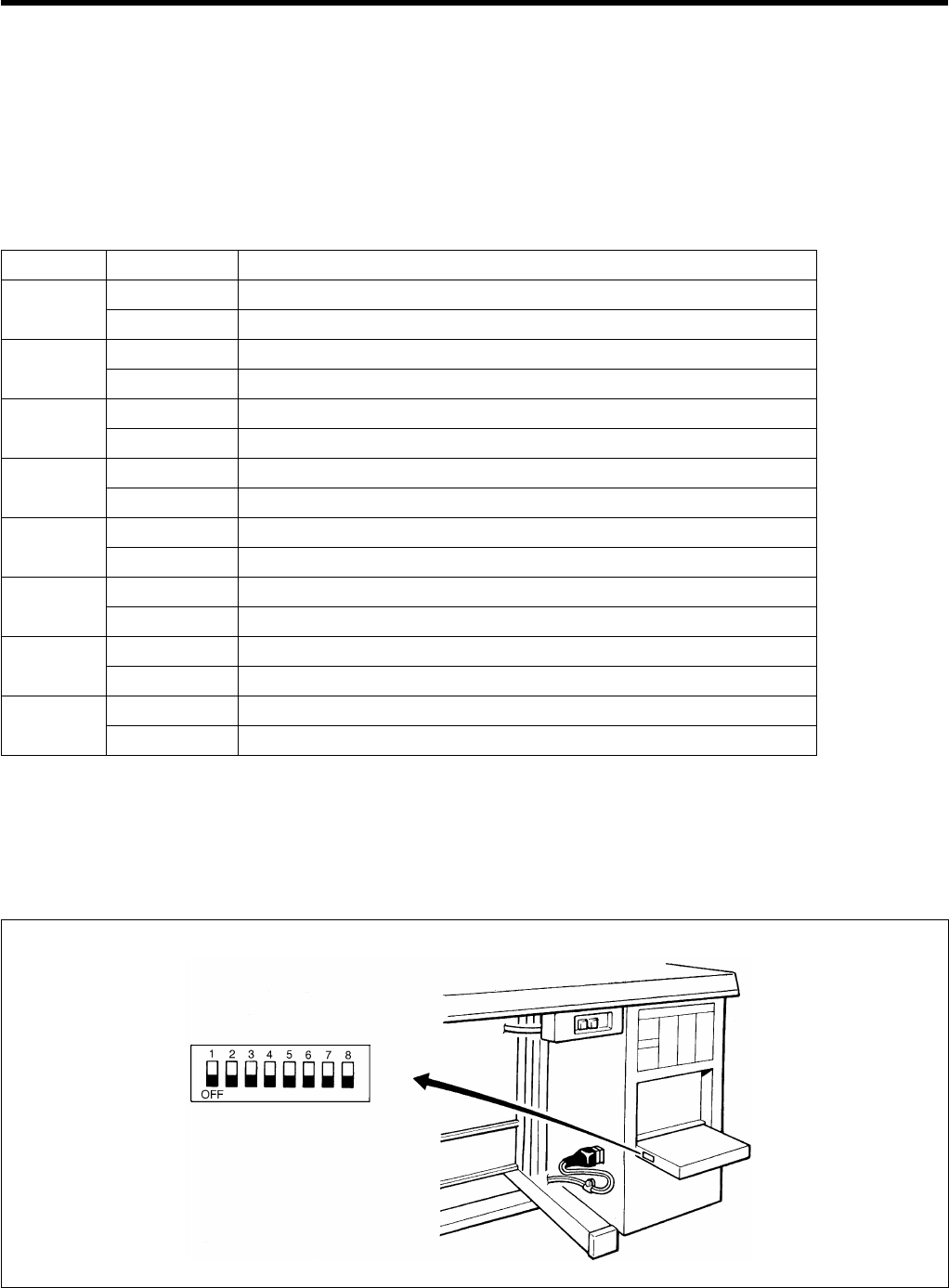
10. SUMMARY OF DIP SWITCHES
RH-9800
56
10. SUMMARY OF DIP SWITCHES
Always turn off the power supply before changing any of the DIP switch settings.
10-1. Front panel DIP switches
The ON/OFF positions of the DIP switches inside the front panel are checked only once when the power is turned on.
Any changes to the DIP switch positions will not be effective until the power is switched off and back on again.
No. ON/OFF Description
ON Program mode disabled
1 *1
OFF Program mode enabled
ON Spare
2OFF Spare
ON Front position
3OFF Back position
ON Counting down to zero
4OFF Counting up from zero
ON Pedal 1 operation
5OFF Pedal 2 operation
ON Compatible with normally closed-type emergency stop switch (new)
6 *3
OFF Compatible with normally open-type emergency stop switch (old)
ON Upper thread remaining amount = Large
7 *2
OFF Upper thread remaining amount = Standard
ON Spare
8OFF Spare
*1 The version of the PROM is given as “E1” or later.
*2 The version of the PROM is given as “D1” or later.
*3 The version of the PROM is given as “F1” or later.
If the position of DIP switch No. 4 is changed, the production counter will be reset to zero.
* The machine is shipped from the factory with the DIP switches set as follows.
1192Q
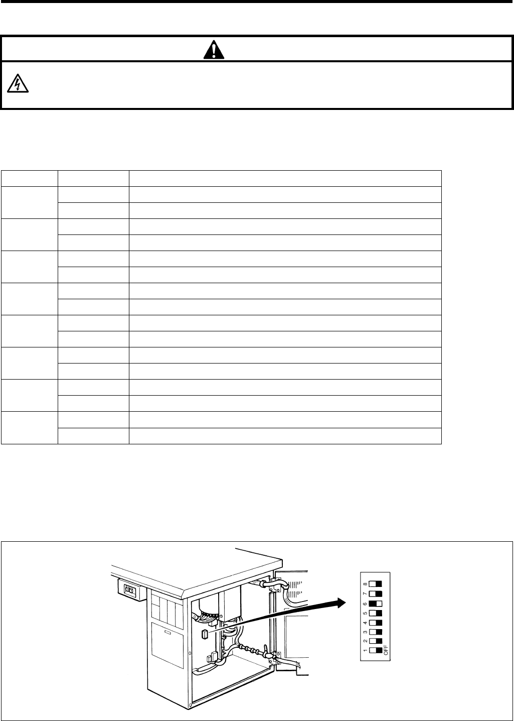
10. SUMMARY OF DIP SWITCHES
RH-9800 57
10-2. Circuit board DIP switches
DANGER
Wait at least 5 minutes after turning off the power switch and disconnecting the power cord from the wall outlet
before opening the face plate of the control box. Touching areas where high voltages are present can result in
severe injury.
The ON/OFF positions of the DIP switches inside the front panel are checked only once when the power is turned on.
Any changes to the DIP switch positions will not be effective until the power is switched off and back on again.
Only one of DIP switch No.1, 2 and 3 is effective at any one time. They are effective in the order 1, 2, 3.
No. ON/OFF Description
ON Data initialization
1OFF Normal
ON Input check
2OFF Normal
ON Output check
3OFF Normal
ON Upper gimp guide present
4 *1
OFF Upper gimp guide not present
ON Upper thread nipper present
5 *2
OFF Upper thread nipper not present
ON Upper and lower thread trimming
6OFF Upper thread trimming
ON Material is remains pressed after sewing
7OFF Material is released after sewing
ON Needle bar returns to home position after set number of pieces sewn
8OFF Needle bar always returns to home position after each piece sewn
*1 The version of the PROM is given as “E1” or later.
*2 The version of the PROM is given as “D1” or later.
If the stitch length has been set to 39 mm or greater, it will be automatically changed to 38 mm if DIP switch No. 6 is
changed to ON.
* The machine is shipped from the factory with the DIP switches set as follows.
1193Q
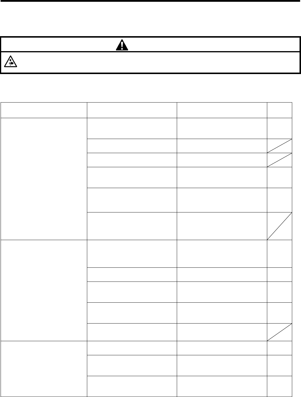
11. TROUBLESHOOTING
RH-9800
58
11. TROUBLESHOOTING
If there is a problem with operation, first check that the threads are correctly threaded and that the needle is correctly
installed.
CAUTION
Turn off the power switch and disconnect the power cord before carrying out troubleshooting, otherwise the
machine will operate if the start switch is pressed by mistake, which could result in injury.
MACHINE HEAD
Problem Cause Remedy Page
Thread tension control nut
pressure is too strong. Adjust to an appropriate pressure. 32
Thread is of poor quality. Use a better-quality thread.
Thread is too thick for the needle. Use a differently-size needle.
Needle groove or needle hole are
not smooth. Replace with a new needle. 16
Needle and looper adjustment is
incorrect.
Adjust the needle bar height or
the looper and spreader height. 43
Thread breaks.
Needle, looper, throat plate or
thread path is damaged.
Repair the damage with an
oilstone or buffer, or replace the
damaged part.
Thread tension control nut
pressure is too strong or too
weak. Adjust to an appropriate pressure. 32
Needle point is broken or bent. Replace with a new needle. 16
Needle and looper adjustment is
incorrect, or clearance is incorrect. Adjust correctly. 44
Needle and needle guard
adjustment is incorrect. Adjust correctly. 47
Skipped stitches occur.
Looper tip is blunt. Repair with an oilstone or replace
the looper with a new one.
Needle is bent. Replace with a new needle. 16
Needle and looper adjustment is
incorrect. Adjust the needle bar height or
the looper and spreader height. 43
Needle breaks.
Needle and needle guard
adjustment is incorrect. Adjust correctly. 47

11. TROUBLESHOOTING
RH-9800 59
Problem Cause Remedy Page
Knife is blunt. Replace with a new knife. 51
Knife does not move to the full
stroke because air pressure is too
weak. Adjust the air pressure. 51
Upper thread trimmer knife is not
picking up the upper thread.
Install the upper thread trimmer
knife so that it cuts only one side
of the upper thread loop. 53
Movable knife is not picking up
the needle thread because the
last stitch is being skipped.
Refer to the remedies given under
“Skipped stitches occur” in this
troubleshooting chart. 58
Upper thread is not cut.
Movable knife position is
incorrect. Adjust the position of the movable
knife or the loop spreader. 53
Knife is blunt. Replace with a new knife. 51
Knife does not move to the full
stroke because air pressure is too
weak. Adjust the air pressure. 51
Lower thread is not cut.
Movable knife position is
incorrect. Adjust the position of the movable
knife or the loop spreader. 53
Thread nipper spring force is too
weak. Adjust the force of the thread
nipper spring. 53
Upper thread length is too short
after trimming.
Install the upper thread trimmer
knife so that it cuts only one side
of the upper thread loop. 53
Needle and looper adjustment is
incorrect. Adjust the needle bar height or
the looper and spreader height. 43
Thread slips out of the
needle at the sewing
start.
Not enough upper thread is being
fed out. Adjust the amount of upper thread
being fed out. 45
Cutting pressure is too weak. Adjust the cutting pressure so that
it is strong enough. 51
Knife and cutting block are not
contacting properly. Grind the cutting block surface. 50
Knife is blunt. Replace with a new knife. 51
Material is not being cut
cleanly.
Cutter arm operation time is too
short.
Make the operation time longer by
changing the memory switch
setting. 49

INSTRUCTION MANUAL
15-1, Naeshiro-cho, Mizuho-ku, Nagoya 467-8561, Japan. Phone: 81-52-824-2177
Printed in Japan
BROTHER INDUSTRIES, LTD.
118-980
S91980-302
2001.11. H (1)
