Bruno Independent Living Aids PCB4950 Stairway Elevator Remote Control User Manual SRE 1550 LS research
Bruno Independent Living Aids Inc Stairway Elevator Remote Control SRE 1550 LS research
Contents
- 1. Cover Page
- 2. Table of Contents
- 3. FCC Conformity
- 4. Preface
- 5. Preface Continued
- 6. Installation
- 7. Installation Continued
- 8. Reverse Operation Instruction
- 9. Circuit Board Operation
- 10. Circuit Operation
- 11. Installation of Remote Call
- 12. Call Send Code Operation
- 13. Schematic Diagram
- 14. Exploded View Chair
- 15. Exploded View Chair Parts List
- 16. Exploded View Rail
- 17. Exploded View Rail Parts List
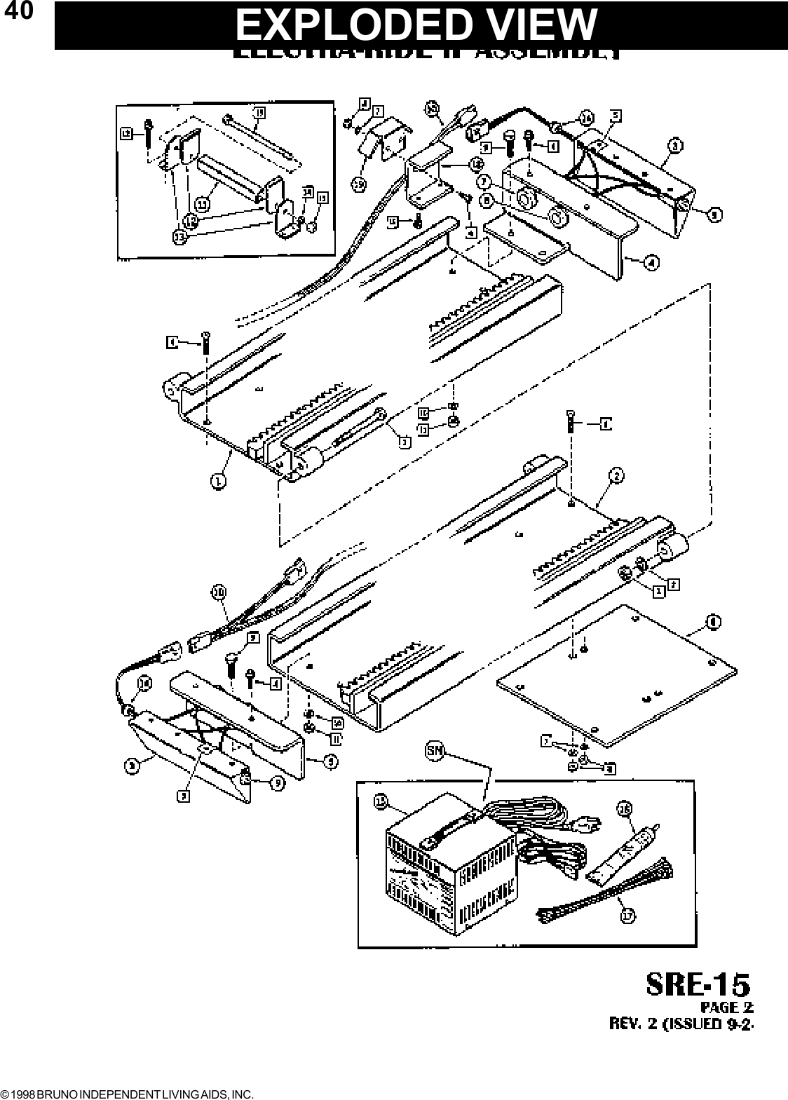
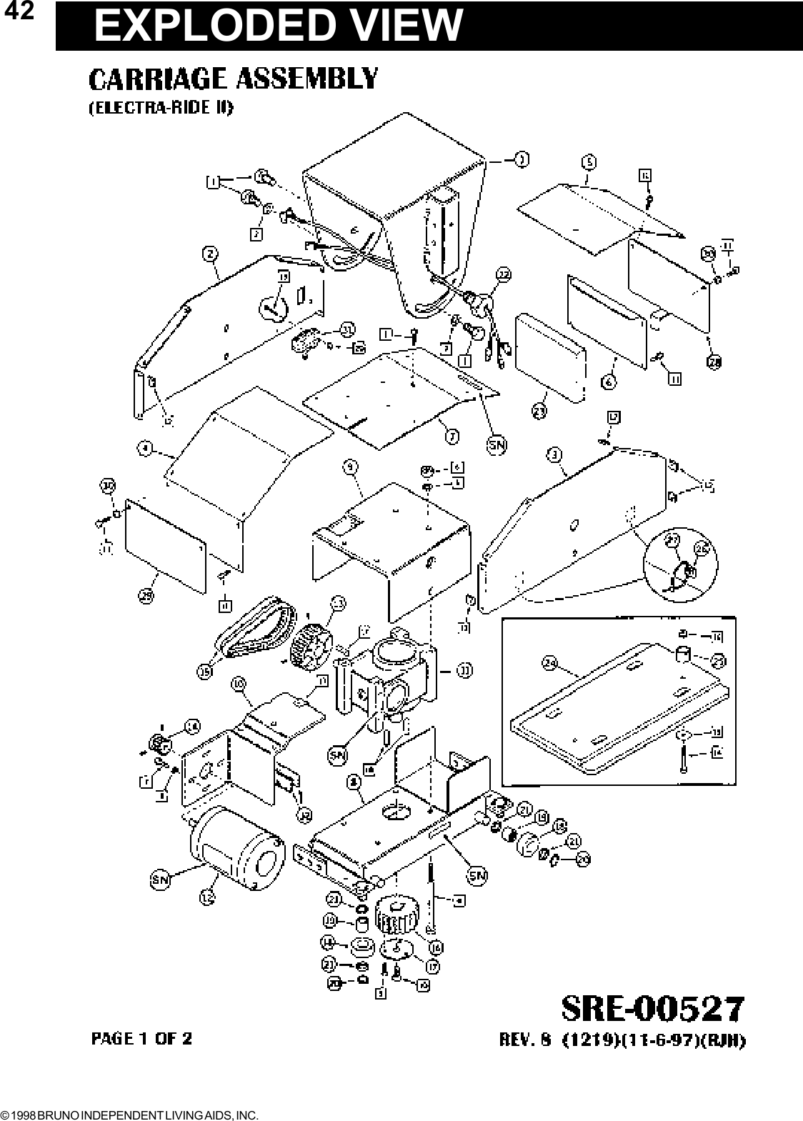
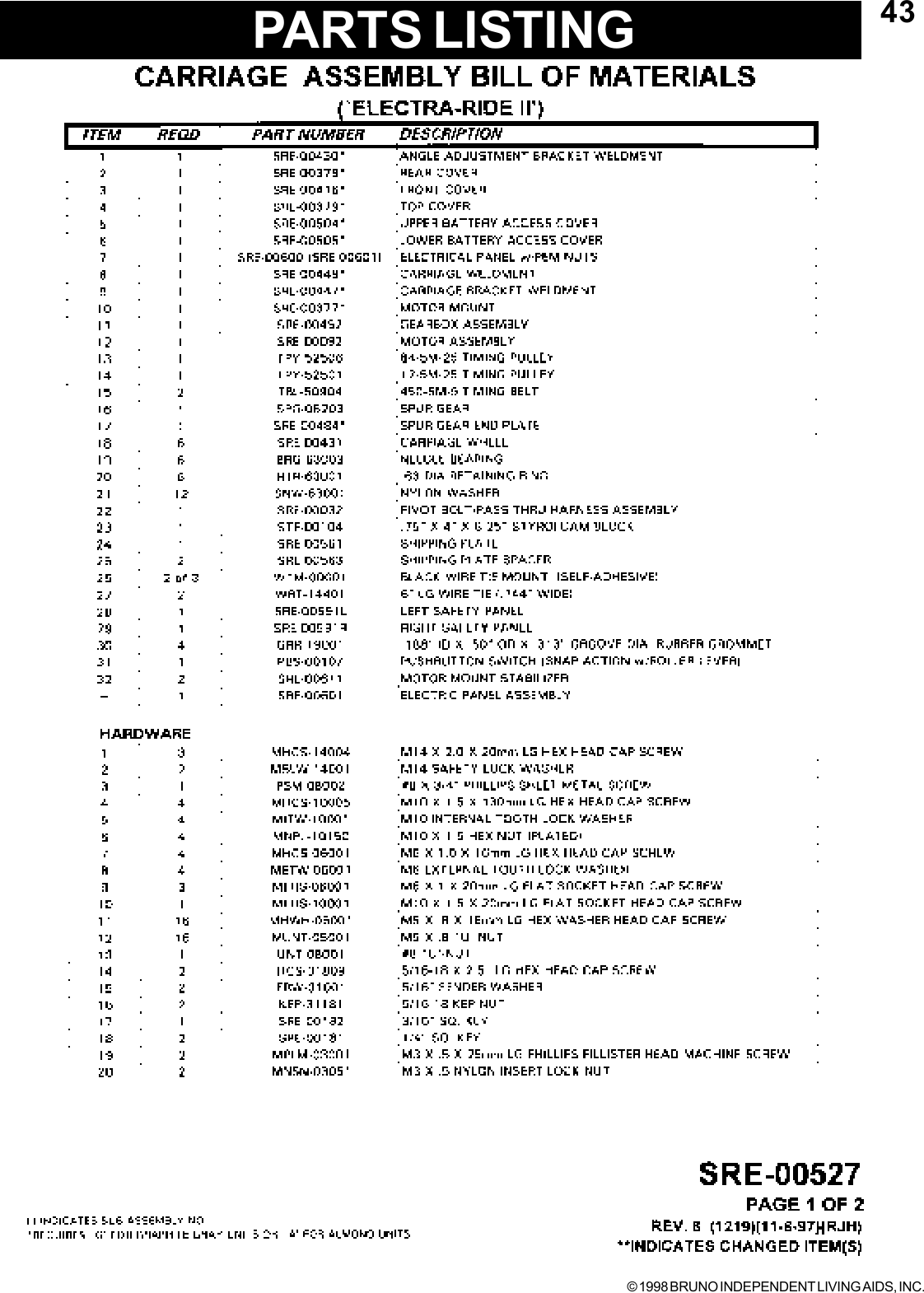
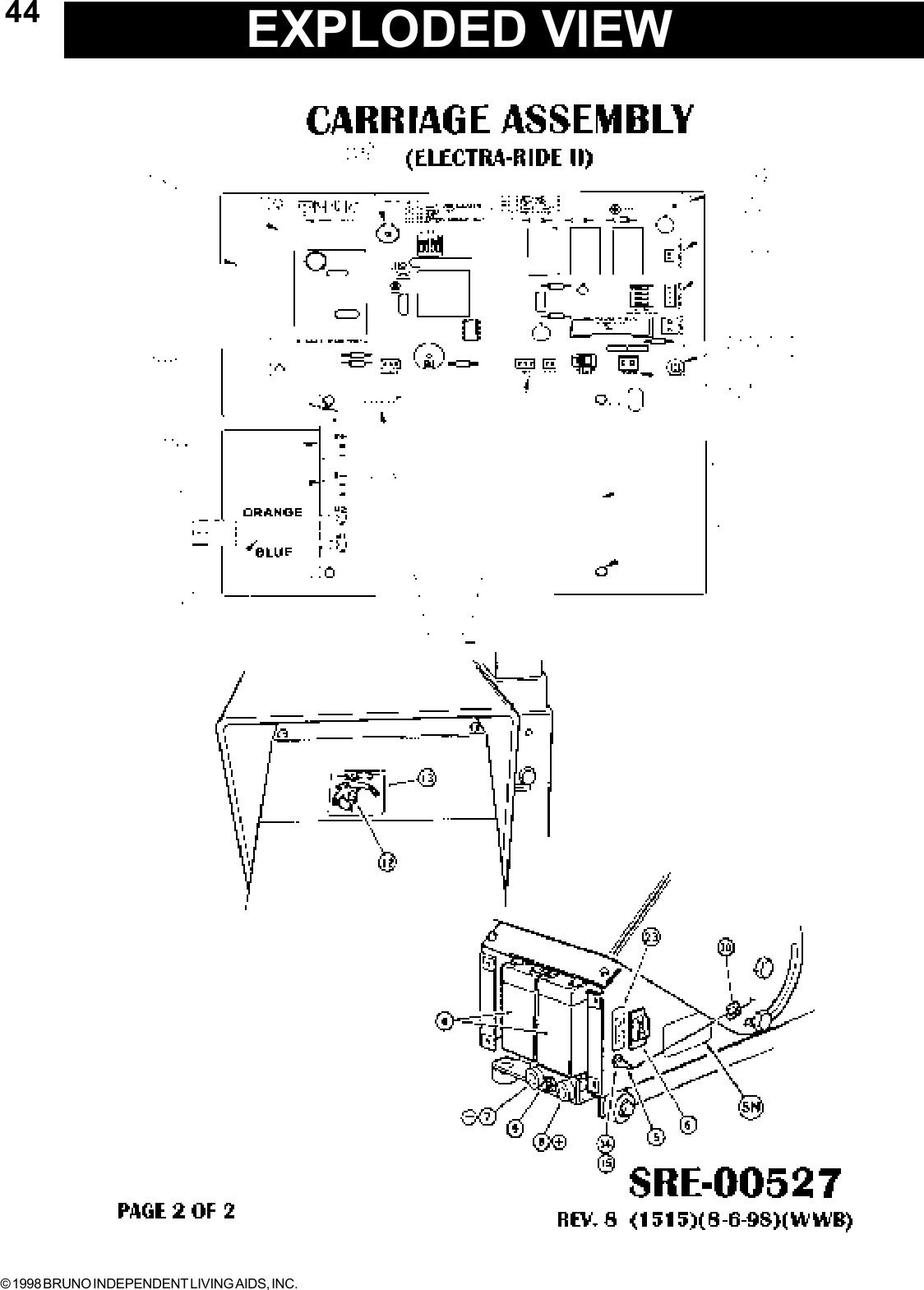
- 18. Exploded View Carriage
- 19. Exploded View Carriage Assembly
- 20. Exploded View Carriage Asst Parts List
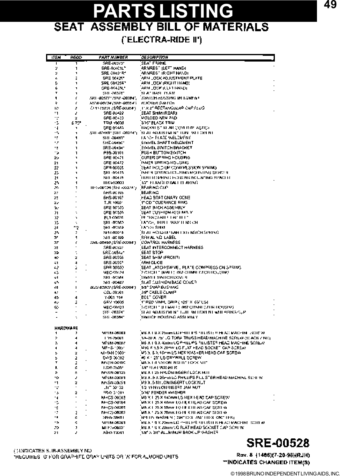
- 21. Exploded View Seat Assembly
- 22. Exploded View Seat Assy Parts List
- 23. Updates PDF Users Manual
Updates PDF Users Manual
![© 1998 BRUNO INDEPENDENT LIVING AIDS, INC.2The ELECTRA-RIDE II is shipped in 5 cartons. Check the contentsof the cartons to be sure you have all of the components before begin-ning an installation.Check the carton contents for shipping damage upon receipt. Dam-age claims must be filed by the Dealer, not the Manufacturer. BrunoIndependent Living Aids cannot be responsible for shipping damage.CARTON 1[ ] 1 EA. COMPLETE CARRIAGE ASSEMBLY[ ] 2 EA. BUMPER ASSEMBLIES[ ] 1 EA. SRE-K-1553 BUMPER ASSEMBLY. PARTS KIT4 EA. M8 EXT. TOOTH WASHER4 EA. M8 X 1.25 X 20mm LG. HEX HD. CAP SCREW4 EA. M8 X 1.25 METRIC HEX NUT (PLATED)CARTON 2[ ] 1 EA. FOOTREST ASSEMBLY[ ] 8 EA. RAIL CLAMP ASSEMBLIES[ ] 1 EA. BATTERY CHARGER[ ] 2 EA. CALL / SEND TRANSMITTERS[ ] 32 EA. (16' RAIL) 40 EA. (20' RAIL) SHEETMETAL SCREWS (M 6.3 X 50 MM)[ ] 1 EA. SRE-K-1501 ELEC. PARTS KIT[ ] 1 EA. CHARGER HOOKUP WIRE HARNESS[ ] 1 EA. FUSE (AGC 5)[ ] 1 EA.*WHITE LITHIUM GREASE (16' RAIL), 2 EA. (20 ' RAIL)[ ] 10 EA. WIRE TIESCARTON 3[ ] 1 EA. SEAT ASSEMBLY[ ] 0 EA. (16' RAIL), 2 EA. (20' RAIL), [__] EA.(CUSTOM RAIL) CLAMP SETSCARTON 4[ ] 1 EA. RAIL SECTIONCARTON 5[ ] 1 EA. RAIL SECTION[ ] 1 EA. JOINT PLATE[ ] 1 EA. SRE-K-1502 HARDWARE KIT (JOINT PLATE)[ ] 8 EA. M6 X 16 FLAT HEAD SCREWS[ ] 8 EA. M6 HEX NUTSPACKING LIST*MSDS (MATERIALSAFETY DATA SHEET)AVAILABLE FROMBRUNO UPONREQUEST CONTACTSERVICEDEPARTMENT](https://usermanual.wiki/Bruno-Independent-Living-Aids/PCB4950.Updates-PDF-Users-Manual/User-Guide-8821-Page-2.png)
![© 1998 BRUNO INDEPENDENT LIVING AIDS, INC.5NOTE: THE STANDARDSTAIRWAY ELEVATORIS SUITABLE FORSTAIRWAY ANGLES UPTO 45 DEGREES.BE SURE YOU HAVEALL NECESSARYPARTS AND TOOLS BEFORE TRAVELINGTO INSTALLATION SITE.INSTALLATIONTOOLS NECESSARY FOR INSTALLATION[ ] PROTRACTOR LEVEL, BUILDERS LEVEL[ ] METRIC SOCKET SET (10 MM THROUGH 22 MM)[ ] RATCHET, W / 6" EXTENSION[ ] COMBINATION WRENCH SET (METRIC, 22 THROUGH36 MM)[ ] PHILLIPS SCREWDRIVERS[ ] SLOTTED SCREWDRIVERS[ ] METRIC ALLEN WRENCHES (3MM MINIMUM SIZE)[ ] ELECTRIC DRILL WITH LETTER `O' (.316") AND 1/4" BIT[ ] HACKSAW WITH 2 OR 3 BLADES OR METAL CUTTINGBANDSAW[ ] 20 FOOT TAPE MEASURE[ ] SMALL RUBBER MALLET[ ] C-CLAMP[ ] FLASH LIGHT[ ] 5/16" OPEN ENDED WRENCH[ ] NEEDLE NOSE PLIERS[ ] SCISSOR OR KNIFE[ ] EXTENSION CORD[ ] DOUBLE SIDED FOAM TAPE[ ] FILE[ ] 12" ADJUSTABLE WRENCH](https://usermanual.wiki/Bruno-Independent-Living-Aids/PCB4950.Updates-PDF-Users-Manual/User-Guide-8821-Page-5.png)
![© 1998 BRUNO INDEPENDENT LIVING AIDS, INC.6INSTALLATIONASSEMBLYFIGURE 1FITTING THE RAIL[ ] Determine whether the elevator should be a left or rightside installation. "Left" or "right" installation is determinedby the side of the stairway on which the rail is installed(viewed from the bottom of the stairs). Unless specifiedotherwise Bruno Stairway Elevators are set up for left sideinstallation as shipped, and can easily be converted to right sideinstallation (instructions included in this manual on page 15).[ ] Identify and locate lower rail section for the left or rightinstallation.BUMPER BRACKET INSTALLATION[ ] Assemble lower rail, install Bumper Bracket.[ ] Determine the correct length for the Rail by measuringalong a straight line placed on the stairs. (SEE STEP 2 INTHE APPLICATION GUIDE) Add to that amountmeasurement B (STEP 4 IN THE APPLICATION GUIDE). Thisprocess will allow you to custom fit the elevator to yourcustomer taking into consideration the most comfortableseat to floor height within the space available at the top ofthe stairs.NOTE: THE RAIL MUST REST APPROXIMATELY 1/2" TO 1" ABOVENOSING OF THE STEPS AND EXTEND FROM THE LOWERFLOOR TO A POINT BEYOND THE NOSING OF THE TOP STEP(SEE APPLICATION GUIDE STEP 4). IN SOME CASES WHERETHE BOTTOM LANDING IS MADE OF MATERIAL SUCH AS(CONCRETE, CERAMIC TILE OR SLATE) THE LAST BRACKET ONTHE LANDING MAY BE OMITTED WITH A BRACKET ADDED ONTHE SECOND STEP FROM THE BOTTOM AND TOP OF STAIR-WAY.BUMPER BRACKETCAUTION:THIS RAIL MUST BEINSTALLED 1/2" TO 1"ABOVE NOSING OFSTAIRS, OR THEFOOTREST WILL HITTHE STEPS CAUSINGINTERMITTENTOPERATION.](https://usermanual.wiki/Bruno-Independent-Living-Aids/PCB4950.Updates-PDF-Users-Manual/User-Guide-8821-Page-6.png)
![© 1998 BRUNO INDEPENDENT LIVING AIDS, INC.7INSTALLATIONCUTTING THE RAIL[ ] Use a metal-cutting power-saw or manual hacksaw to cutthe rail to length. Cut off the end of the rail which will be located atthe top of the stairway.[ ] Use a file or other appropriate tool to de-burr the cut end ofthe rail. Soften any sharp edges which might abrade theinsulation from wiring which must be routed to the bumper at theend of the rail.[ ] Use a C-clamp to hold the upper Bumper Bracket in place inthe cut end of the rail and use the holes in the Bumper Bracketas guides to drill mounting holes using “O” size (8.03 MM/.316")drill bit in the rail.[ ] Assemble the Rail joint by attaching the Bottom Plate toRail with M6 X 20 Flat Head Screws, external-tooth Lockwashers and M6 Hex Nuts. Install the M10 Bolts, M10 internaltooth Washer and M10 hex nut through the Joint Blocks on bothsides of the Rail. Tighten all bolts securely and make sure screwheads are flush with the surface of the inside of the Rail.NOTE:THE CHAMFERED EDGES OF THEHOLES MUST FACE "UP" TOWARDTHE BOTTOM OF THE RAIL.FIGURE 2FIGURE 3NOTE:THE RAIL IS ALWAYSINSTALLED WITH THEGEAR RACK TOWARDSTHE CENTER OF THESTAIRS AND GEAR TEETHFACING REAR OF UNIT.RAIL JOINT ASSEMBLYUSE “O” SIZE DRILLBIT (8.03MM/.316")](https://usermanual.wiki/Bruno-Independent-Living-Aids/PCB4950.Updates-PDF-Users-Manual/User-Guide-8821-Page-7.png)
![© 1998 BRUNO INDEPENDENT LIVING AIDS, INC.8[ ] Install rail mounting foot clamps in the placement patternas follows: (leaving a minimum of 1/2" from the wall.)(See figure 5)*BOTTOM OF RAIL*FIRST STEP UP FROM BOTTOM OF RAIL*TOP STEP OR LANDING*EVERY OTHER STEP BETWEEN TOP AND BOTTOM*EXCEPT ONE ON STEPS EACH SIDE OF RAIL JOINTNOTE: IF TOP OR BOTTOM CLAMP IS OMITTED BECAUSE THELANDING IS CEMENT OR CERAMIC TILE OR ANOTHER SUB-STANCE THAT THE OWNER DOESN'T WANT HOLES IN, A SETOF CLAMPS SHOULD BE ADDED ON THE SECOND LAST STEPAND AT THE TOP OF STAIRWAY.[ ] For ease of installation, finger tighten all clamps to rail.The clamp assembly should be positioned so the nut isclosest to the wall. (See figure 4 & 5)[ ] Slide top and bottom clamps down until firmly seated onstep. When installing on carpeted stairs a rubber malletshould be used on clamps to compress carpet and cushionbefore anchoring to steps.[ ] Install securely one screw near the wall on top and bottomof foot of clamp assemblies. This will enable the installerto change position of the rail if necessary and preventdrilling excess holes.POSITION RAIL CLAMP ASSEMBLIESINSTALLATIONFIGURE 4*NOTE:CHECK ARM WIDTHREQUIRED BYCUSTOMER. IF THEARMS ARE ADJUSTEDWIDER THANNORMAL, THEN THEDISTANCE FROM THEWALL WILL HAVE TOINCREASE GREATERTHAN 2 1/2" IFSWIVELING AGAINSTA WALL.(SEE PAGE 25)](https://usermanual.wiki/Bruno-Independent-Living-Aids/PCB4950.Updates-PDF-Users-Manual/User-Guide-8821-Page-8.png)
![© 1998 BRUNO INDEPENDENT LIVING AIDS, INC.9FIGURE 5*IF SEAT NEEDS TOSWIVEL AGAINST WALL,APPROXIMATELY 2 1/2"FROM WALL,ADDITIONALCLEARANCE WILL BENEEDED CALL/SEND ANTENNA INSTALLATIONRAILRAIL MOUNTING FOOTCLAMP ASSEMBLY1/2" TO 1"ABOVE NOSING[ ] Install the Call/Send Antenna on the rear side of carriage.Take care to place the Antenna in a horizontal position.POSITION RAIL CLAMP ASSEMBLIES[ ] Make sure to use the measurements in (figure 5) as a guidefor positioning Clamp assemblies.INSTALLATIONFIGURE 6*NOTE: IF THE UNIT WILL HAVE TO SWIVELAGAINST A WALL AT EITHER ENDOF THE RAIL, ADDITIONAL DISTANCEWILL BE NEEDED BETWEEN THE RAILAND THE WALL. CHECK CLEARANCESBEFORE SECURING TO STAIRS.CALL/SENDANTENNA](https://usermanual.wiki/Bruno-Independent-Living-Aids/PCB4950.Updates-PDF-Users-Manual/User-Guide-8821-Page-9.png)
![© 1998 BRUNO INDEPENDENT LIVING AIDS, INC.10[ ] Turn Toggle Switch off. When facing front of unit, removeleft motor cover. Slide the carriage into the Rail until thespur gear rests on the gear rack. Manually turn themotor pulley to fully engage the entire carriage inside theupper rail.[ ] Adjust the carriage angle by loosening the Angle Adjust-ment Bolts (shown in figure 7). Level the Angle AdjustmentBracket, using a standard builders level or protractor level.When the Angle Adjustment Bracket is level securelytighten all four Angle Adjustment Bolts*.INSTALLATIONMOUNT THE CARRIAGE ON THE UPPER RAILFIGURE 7ADJUST THE CARRIAGE ANGLE ANGLE ADJUSTMENT BRACKETANGLE ADJUSTMENTBOLTSNOTE:*RECHECK WITH LEVELAFTER TIGHTENINGADJUSTMENT BOLTS.](https://usermanual.wiki/Bruno-Independent-Living-Aids/PCB4950.Updates-PDF-Users-Manual/User-Guide-8821-Page-10.png)
![© 1998 BRUNO INDEPENDENT LIVING AIDS, INC.11[ ] Feed the five conductor lead through the hollow tubeunder the seat. Insert seat frame post into the outermounting tube. Determine the correct seat height theninsert bolt in desired hole leaving the head of the boltprotruding 3/8" from the mounting tube. (As shown infigure 9). Fish excess wires into hole on Front Pivot Bolt.[ ] Remove Footrest Assembly, then gently pull extra wirefrom hole in Pivot Bolt. Then remove bolt in seat adjust-ment tube weldment. Adjust seat height, replace bolt andsecure. Reinsert extra wire in Pivot Bolt, replace FootrestAssembly.INSTALL SEAT ASSEMBLYFIGURE 8INSTALL SEAT ASSEMBLY AS SHOWNINSTALLATIONSEAT HEIGHT ADJUSTMENTFRONT PIVOT BOLT](https://usermanual.wiki/Bruno-Independent-Living-Aids/PCB4950.Updates-PDF-Users-Manual/User-Guide-8821-Page-11.png)
![© 1998 BRUNO INDEPENDENT LIVING AIDS, INC.12OUTER MOUNTINGTUBE FOOTREST ASSEMBLYFIGURE 9INSTALLATIONConnect the wires as shown in illustration (See figure 9). Tuckexcess wires in Outer Mounting Tube just below the bolt in SeatAdjustment Tube. While holding the wires in place bring thefootrest close to the carriage near the Pivot Bolt, tilt the Footrestslightly while raising it up and over the Bolt until it is engaged inthe slot.NOTE: BE CAREFUL NOT TO PINCH THE WIRES WHILESLIDING THE FOOTREST OVER THE BOLT.[ ] With the seat in the central riding position, move theelevator completely down and up the rail, whileobserving the elevator to wall clearance. A clearance of1/2" to 1" is acceptable. Repeat the run with the seatin the folded position. If necessary, adjust the railplacement by sliding it closer or further from the wall.[ ] Test the unit for proper: speed, direction, Limit Switchoperation, Footrest Safety Switch operation, SeatSwivel Safety Switch operation and Remote Call/Sendoperation.PIVOT BOLTFOOTREST HANGERFOOTREST SWITCHBRACKETELECTRA-RIDE II TRIAL RUN](https://usermanual.wiki/Bruno-Independent-Living-Aids/PCB4950.Updates-PDF-Users-Manual/User-Guide-8821-Page-12.png)
![© 1998 BRUNO INDEPENDENT LIVING AIDS, INC.13 [ ] The footrest comes equipped with a safety switch whichwill stop the elevator in the event that something becomestrapped between the footrest and a stair tread. Confirmcorrect operation of this feature by moving the sliding tray(BOTH SIDES) while operating the elevator. The elevatorwill stop if this feature is operating correctly.The Carriage comes equipped with a Safety Switch Panel.As the Carriage approaches the end of the Rail, the Panel isdepressed, which activates the Switch, and stops the carriage.FIGURE 10INSTALLATIONSAFETY SWITCHFOOTRESTSAFETY SWITCHNOTE:MAKE SURECALL/SEND ANTENNAHAS CLEARANCE FORENTIRE TRAVEL OFRAIL. SAFETYSWITCH PANELFIGURE 11SAFETY SWITCH PANEL](https://usermanual.wiki/Bruno-Independent-Living-Aids/PCB4950.Updates-PDF-Users-Manual/User-Guide-8821-Page-13.png)
![© 1998 BRUNO INDEPENDENT LIVING AIDS, INC.15[ ] The elevator is shipped set up for a left side installation (onyour left as you view the elevator from the bottom of thestairs.) Should the installation require a right handinstallation observe the following instructions.[ ]Turn the On / Off Circuit Breaker on the rear of carriage to`OFF'.[ ] Remove Left Carriage Cover.[ ] Set the Installation DIP Switch (S2) to the `RH' position.[ ] Set the No. 1 DIP Switch on the 4-Ganged Dip Switch(SW1) to the `OFF' position.[ ] Check that the Power Switch (S3) is turned `ON' .[ ] Unplug the Motor Leads and reverse connections.[ ] Turn the Circuit Breaker Switch to the “ON” position.[ ] Replace the Carriage Cover.[ ] Remove the Switch Housing weldment by removing thephillips head machine screw under the arm. Thetrim holding the harness on the backside of the arm slidesoff. Disconnect the harness under the seat and route theharness through the opposite side. Fasten the switch hous-ing on the left arm and reconnect the harness. Slide thetrim over the harness on the backside of the arm.REVERSING OPERATIONINSTALLATION ON RIGHT SIDE OF STAIRWAYFIGURE 13CHANGING CONTROLS FROM RIGHT TO LEFT ARMRESTCHANGING CONTROLS FROM RIGHT TO LEFT ARMRESTFLIP THEINSTALLATIONDIP SWITCHFROM `LH' TO`RH' POSITIONFLIP NO. 1SWITCHTO THE `OFF'POSITIONREVERSING CONNECTIONSCIRCUIT BOARDPOWER DIPSWITCH S3](https://usermanual.wiki/Bruno-Independent-Living-Aids/PCB4950.Updates-PDF-Users-Manual/User-Guide-8821-Page-15.png)
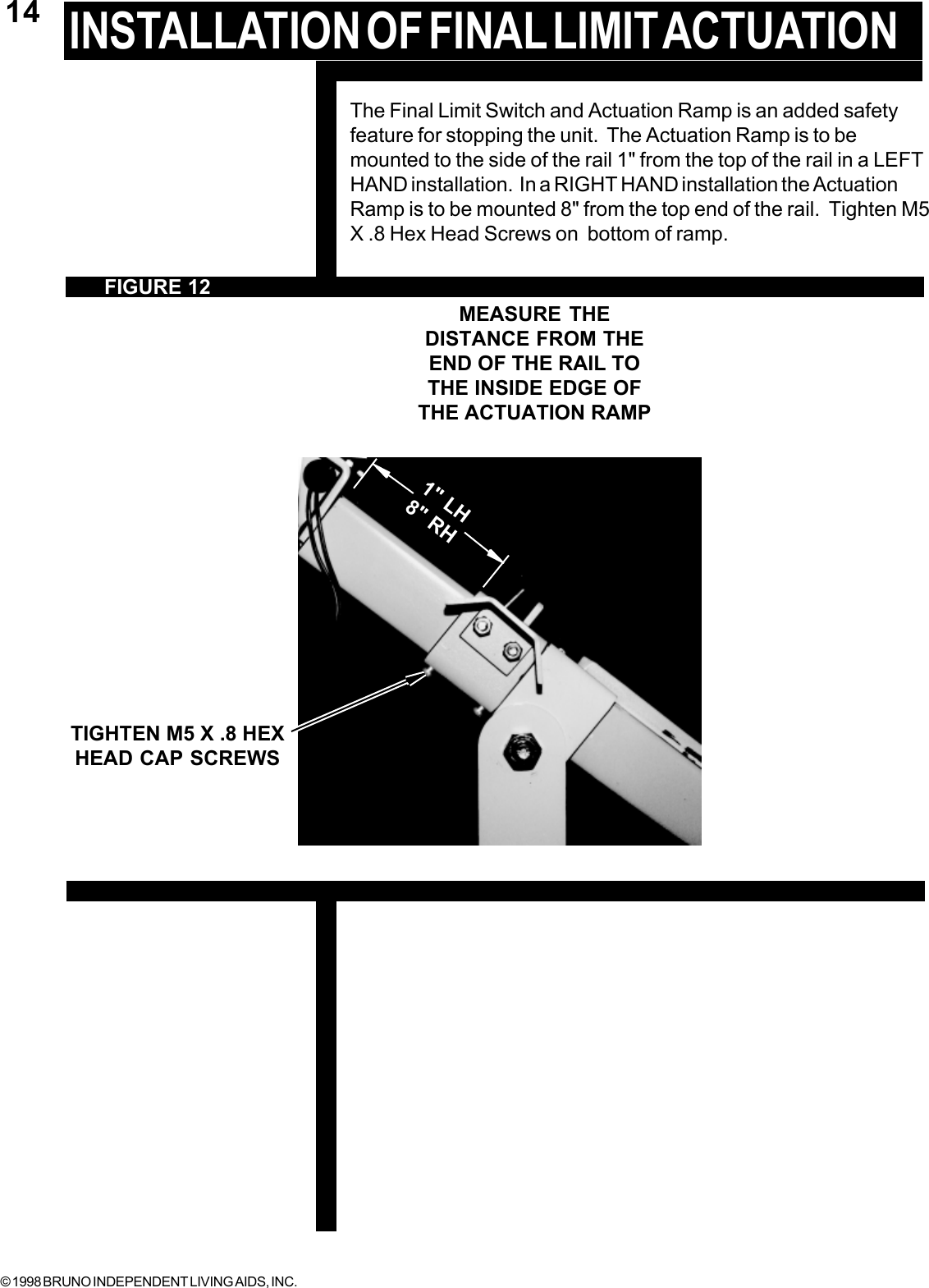
![© 1998 BRUNO INDEPENDENT LIVING AIDS, INC.18 INSTALLATIONINSTALL FOOT CLAMPSRECHECK NOTE:BEFORE TIGHTENINGTHE BRACKETSCHECK TO MAKESURE THAT THEBUMPER WIRES ARENOT TRAPPED UNDERBUMPER BRACKET ATLOWER LANDINGNOTE:IF THREADED FASTENEREXTENDS BELOW ASTAIR TREAD THAT ISEXPOSED, IT CAN BETRIMMED FLUSH WITH APLIERS. [ ] Check that the foot clamp base position is a minimum of1/2" from the wall.NOTE: THE STAIRWAY ELEVATOR COMESWITH FASTENERS APPROPRIATE FOR WOODENSTAIR TREADS ONLY. OTHER STAIR MATERIALMAY REQUIRE DIFFERENT FASTENERS (CONTACTBRUNO INDEPENDENT LIVING AIDS FOR FURTHERASSISTANCE). (NOTE: FOR HARDWOOD STAIRS, IT ISRECOMMENDED THAT A PILOT HOLE BE DRILLEDBEFORE SCREWING IN FASTENERS).[ ] Once rail position is confirmed, place one screw in eachbracket to hold rail in place while tightening to rail.(This will prevent mounting feet from rotating while bolt isbeing tightened.)[ ] Tighten rail bolt and install the rest of the screws inbracket, then tighten securely.[ ] Install the upper bumper bracket to rail.INSTALL THE UPPER BUMPER BRACKETFIGURE 14](https://usermanual.wiki/Bruno-Independent-Living-Aids/PCB4950.Updates-PDF-Users-Manual/User-Guide-8821-Page-18.png)
![© 1998 BRUNO INDEPENDENT LIVING AIDS, INC.19[ ] Install the upper bumper bracket to rail.[ ] Apply a coating of White *Lithium Grease to theGear Rack and inner flanges of the Stair Rail as shown.1 TUBES PER 16 FOOT UNIT2 TUBES PER 20 FOOT UNIT[ ] Position the Charger in a suitable permanent location.[ ] Install the wiring harness on the Elevator Rail andconnect to the Charger as shown.INSTALL THE UPPER BUMPER BRACKETCHARGER/RAIL LEAD APPLICATIONFIGURE 16FIGURE 15LUBRICATIONINSTALLATIONNOTE: GEAR RACK TEETHFACE WALL OF STAIRWAYRAIL BUMPERRED CONNECTORS WALLAPPLY A LIGHT COATING OF WHITELITHIUM GREASE TO THESE SURFACELIGHT .GEAR RACK](https://usermanual.wiki/Bruno-Independent-Living-Aids/PCB4950.Updates-PDF-Users-Manual/User-Guide-8821-Page-19.png)
![© 1998 BRUNO INDEPENDENT LIVING AIDS, INC.20[ ] Make the connections to the Charger Wiring Harness.[ ] Route the Charger Wiring Harness along the back sideof the Rail and secure it to the Rail Mounting Clampswith wire ties. Be sure that this wiring is mountedsecurely so that it is not vulnerable to physical damage.[ ] Coil any excess harness wire and attach to a Rail Clamp(under the rail).NOTE: THE CHARGER SHOULD BE PLUGGED INTO AHOUSEHOLD OUTLET ALL OF THE TIME. THE ELEVATOR ISDESIGNED SO THAT THE BATTERIES WILL BE CHARGEDWHEN THE CARRIAGE IS AT ONE OR THE OTHER END OFTHE RAIL. IT IS IMPERATIVE THAT THE CARRIAGE BE"PARKED" AT THE END OF THE RAIL WHEN IT IS NOT IN USETO MAINTAIN FULL BATTERY CHARGE.IN AN INSTALLATION WHERE THE CARRIAGE CAN NOT BEPARKED AT THE END OF THE RAIL (STAIRWAYS WITH ADOOR AT THE TOP, FOR EXAMPLE), THE CARRIAGESHOULD BE RUN TO THE OTHER END OF THE RAIL WITHTHE REMOTE CALL/SEND MODULE WHEN NOT IN USE.THIS WILL ENSURE THAT THE BATTERIES WILL REMAINFULLY CHARGED.FIGURE 17SUGGESTION:AFTER ROUTING THEWIRE HARNESS OUT OFSIGHT A SMALL PIECEOF DOUBLE SIDEDFOAM TAPE CAN BEAPPLIED TO THEHARNESS PLUGS ANDATTACH UNDER THERAIL.NOTE: IF CHARGER PLUG ANDWIRE ARE LOCATED INA VULNERABLELOCATION, A PLUGLOCK TO PREVENTACCIDENTALUNPLUGGING ISRECOMMENDED.THESE ARE AVAILABLEAT HARDWARE ANDDEPARTMENT STORES.RAIL CHARGER LEADLEAD TO BATTERYCHARGER WIRINGHARNESSROUTING WIRE HARNESSESINSTALLATION](https://usermanual.wiki/Bruno-Independent-Living-Aids/PCB4950.Updates-PDF-Users-Manual/User-Guide-8821-Page-20.png)
![© 1998 BRUNO INDEPENDENT LIVING AIDS, INC.21INSTALLATION / REMOTE CALL/SENDMOUNTING THE CALL/SEND MODULESTHE UNITS CAN BE MOUNTED TO A WALL WITH THEADHESIVE-BACKED VELCRO PROVIDED. THE CALL SENDMODULE SHOULD BE MOUNTED SO OPERATOR CANALWAYS VIEW THE ELEVATOR AND OUT OF REACH OFCHILDREN.TESTING THE UNITA SLIGHT DELAY WILL OCCUR BETWEEN THE TIME THEROCKER SWITCH IS DEPRESSED AND THE INITIATION OFCARRIAGE MOVEMENT. THIS IS NORMAL AND IS AFUNCTION OF THE SOFT START FEATURE OF THECONTROLLER.[ ] Run the unit up and down the stairs with the RockerSwitch on the Carriage. The unit should operate in sucha way that the Rocker Switch is depressed in thedesired direction of travel.The unit should travel noticeably faster going up than down.[ ] Run the unit up and down the stairs with the RemoteCall/Send modules. Test both Modules.[ ] Fold the seat into the stored position and run the unit upand down the stairs with the Remote Call/Send Module.FIGURE 18ALWAYS "PARK" THE CARRIAGE AT THE UPPEROR LOWER END OF THE RAIL TO KEEP BATTERIESFULLY CHARGEDPILOT LAMP INDICATES"CHARGING CONTACT" ANDCORRECT POLARITY.BE SURE CHARGER ISPLUGGED INTO A "LIVE"OUTLET.](https://usermanual.wiki/Bruno-Independent-Living-Aids/PCB4950.Updates-PDF-Users-Manual/User-Guide-8821-Page-21.png)
![© 1998 BRUNO INDEPENDENT LIVING AIDS, INC.22 CALL/SEND CODETRANSMITTER BATTERY REPLACEMENTLOOSEN 4 PHILLIPS SCREWS THEN REMOVE BACK OFTRANSMITTER FOR BATTERY REPLACEMENTNOTE: WHILE USING THEREMOTE CALL SEND,SOME INTERMITTENCEMAY BE EXPERIENCED.IT MAY BE A MINORINCONVENIENCE, BUT INNO WAY HARMS ORIMPAIRS THE UNIT. YOUSHOULD EXPERIENCENO INTERRUPTIONWHILE USING ROCKERSWITCH.NOTE:RADIO INTERFERENCECAN OCCUR IF MORETHAN ONE RADIOCONTROL(OR OTHER RADIODEVICE ) IS OPERAT-INGON THE SAMEFREQUENCY. THISCOULD CAUSE THESRE-1550 CALL / SENDFUNCTION TO NOTWORKPROPERLY. FOR BESTPERFORMANCE, MAIN-TAIN A DISTANCEFROMRADIO CONTROLDEVICES ON THE SAMEFREQUENCY. RADIOINTERFERENCE CANALSO OCCUR NEARHIGHVOLTAGE ELECTRICALWIRES, REINFORCEDCONCRETE BUILDINGSOR CB RADIOS.INTERFERENCE MAYBE LESSENED ORELIMINATED BYSETTING THE INTER-CONNECT BOARDDELAY FROM 600mS TO900mS. THIS IS EASILYDONE BY MOVINGSWITCH #1 TOPOSITION 2TRANSMITTERTHREE AAABATTERIESNEEDED FORTRANSMITTER[ 1] Your unit comes with 2 remote controls learned.[ 2] Should you need to add a remote or replace a remote followthese instructions.[ 3] Locate Learn/Erase LED and switch (S4).[4 ] While holding down Learn/Erase switch with LED on, pressremote control switch (up or down) until LED goes out. Thisremote is now `learned'. Repeat this process with all otherremote controls, you may `learn' up to 4 transmitters per unit.[ 5] When a replacement transmitter is needed, thememory must be cleared and all transmitters must be`relearned'.[ ] To clear memory hold down Learn/Erase switch S4 until LEDgoes out (approximately 12 seconds)[ ] Learn new transmitter(s) to receiver.LEARN TRANSMITTER TO RECEIVERHOW TO CLEAR MEMORYNOTE: CALL SENDS ARESHIPPED WITH THEBATTERIESREMOVED.](https://usermanual.wiki/Bruno-Independent-Living-Aids/PCB4950.Updates-PDF-Users-Manual/User-Guide-8821-Page-22.png)
![© 1998 BRUNO INDEPENDENT LIVING AIDS, INC.23SPEED ADJUSTMENTA provision for adjusting speed is one of the unique features of theSRE-1550 Stairway Elevator. The Speed AdjustmentPotentiometer is located on the top of the Carriage and can beadjusted by following this procedure:[ ] Loosen the Collet Nut on the Speed Control Potentiom-eter approximately one-half turn.[ ] Turn the Potentiometer all the way counterclockwise this isthe starting point. Turn the Potentiometer clockwisealigning the slotted shaft with the weight range of the user.[ ] The speed may be adjusted by turning the slotted shaft onthe Potentiometer (clockwise = faster, counterclockwise =slower). With the customer on the unit make several testruns to arrive at the most to appropriate speed setting.[ ] When the speed has been set satisfactorily, retighten thecollet nut. (Recheck speed)SPEED ADJUSTMENTPOTENTIOMETER COLLET NUTFIGURE 20TURN CLOCKWISE, ALIGNINGSLOTTED SHAFT WITH WEIGHTRANGE OF CUSTOMERTURN POTENTIOMETERCOUNTERCLOCKWISE THEN](https://usermanual.wiki/Bruno-Independent-Living-Aids/PCB4950.Updates-PDF-Users-Manual/User-Guide-8821-Page-23.png)
![© 1998 BRUNO INDEPENDENT LIVING AIDS, INC.26A Circuit Breaker is built into the on/off switch and is provided toprotect the Battery / Controller / Motor circuits in the ElevatorCarriage. It is unlikely that this Circuit Breaker will ever “trip” innormal use, but if the Elevator should fail to operate, check theCircuit Breaker and reset it if necessary. If the Circuit Breakershould trip, determine the cause and correct the situation.The most likely cause of a tripped Circuit Breaker would be aforeign object jamming the Rail or Gear Rack or overloading theelevator by exceeding its rated load capacity.A Fuse has been provided to protect the Battery Charging circuitand the Call / Send electronics. The Elevator is shipped with thisFuse installed.[ ] Turn “OFF” the unit using the “ON” / “OFF” switch on the backof the unit.[ ] Disconnect the Battery Charger from the Rail ChargeLead.[ ] Remove carriage cover.[ ] Determine and repair any short circuit which may havecaused the fuse to blow.FUSE AND CIRCUIT BREAKERFIGURE 23ON/OFF SWITCH WITH CIRCUITBREAKER BUILT INCIRCUIT BREAKERTO REPLACE A "BLOWN" FUSE:](https://usermanual.wiki/Bruno-Independent-Living-Aids/PCB4950.Updates-PDF-Users-Manual/User-Guide-8821-Page-26.png)
![© 1998 BRUNO INDEPENDENT LIVING AIDS, INC.27TO REPLACE A "BLOWN" FUSE (CONTINUED)BATTERY CHARGERBATTERY CHARGER FUSE REPLACEMENT:FUSE REPLACEMENT[ ] Use a fuse puller to remove the "old" fuse from PC BoardSpring Clips (be careful to avoid breaking the glass).[ ] Replace the fuse using only a 5 ampere AGC or SFEtype fuse. (See figure 13 on page 15)[ ] Turn the Power Switch to "ON".[ ] Replace the Carriage Cover.[ ] Reconnect the Battery Charger Leads.[ ] Test the unit for proper operation.WHEN THE INSTALLATION IS COMPLETE, TEST THE UNITFOR CORRECT OPERATION OF CALL/SEND, `ON/OFF'SWITCH, FOOTREST, SAFETY SWITCHES, CARRIAGE LIMITSWITCHES AND SEAT SAFETY SWITCH.TRAIN THE CUSTOMER TO USE THE STAIRWAY ELEVATORCORRECTLY AND SAFELY. BE SURE TO HAVE THEM OP-ERATE THE UNIT WHILE YOU ARE THERE TO ANSWER ANYQUESTIONS OR CONCERNS.BATTERY CHARGER SEQUENCE IS AS FOLLOWS:RED LED `ON' = AC Power on (power cord plugged in)YELLOW CONTINUOUS LED = Batteries chargingFLASHING YELLOW LED = Batteries are 80% chargedGREEN CONTINUOUS LED = Batteries in “charge completing”mode (or float / standby condition)If the charger is subject to a power line surge, the AC input fusemay `BLOW' This fuse is located beneath the power cord from thewall outlet to prevent shock hazard, to replace fuse:1) Remove Power Cord from wall outlet and charger socket.2) Pull out on the fuse access panel.3) Remove fuse.4) Replace with the same size and type: (BUSS # GMC 4) 5 x 20mm-4AMP/125V-TIME LAG*NOTE:IF A THE GREENLIGHT IS FLASHINGON THE CHARGER ITIS DUE A PROBLEMWITH THE BATTERY.IF THE BATTERYHAS NOT REACHEDTHE END OF THEFIRST STAGE OFTHE OPERATIONWITHIN 18 HOURS,THE CHARGER MAYDETERMINE THAT APROBLEM EXISTSWITHIN THE BAT-TERY OR THE BAT-TERY IS TOO BIGFOR THECHARGER'S OUTPUTRATING.](https://usermanual.wiki/Bruno-Independent-Living-Aids/PCB4950.Updates-PDF-Users-Manual/User-Guide-8821-Page-27.png)
![© 1998 BRUNO INDEPENDENT LIVING AIDS, INC.28TURNING THE UNIT ONVACATION / LONG TERM STORAGEIf the elevator will not be in use for and extended period of time theunit should be moved 2"-3" away from the lower Charge contactsand the red circuit breaker should be turned off. After the elevatoris in this position, the charger should be unplugged from the walloutlet.DO NOT unplug the charger from the wall outlet unless the circuitbreaker has been turned off. This will result in battery discharge orpremature battery failure.[ ] To turn the unit back on , turn the circuit breaker on, plug thecharger back into the wall outlet.NOTE: The batteries may need to be recharged beforenormal use if the elevator was in the `off ' position for anextended period of time. To do so , simply move the unit tothe LOWER charge contacts, and re-connect the charger tothe wall outlet (circuit breaker `on').](https://usermanual.wiki/Bruno-Independent-Living-Aids/PCB4950.Updates-PDF-Users-Manual/User-Guide-8821-Page-28.png)


![© 1998 BRUNO INDEPENDENT LIVING AIDS, INC.50OVER SPEED ADJUSTMENT FOR COMMERCIAL UNITS[ ] Before installing the carriage the overspeed cam must beadjusted to line up with the overspeed housing.[ ] Looking at the end of the carriage, line the white mark on thecam with the white mark on the over speed housing.[ ] Slide carriage on rail making sure not to move the aline-ment.[ ] If the overspeed should be tripped while servicing orinstalling. The cam may be reset by rotating the cam back to itsdetent position. By bypassing the overspeed switch andrunning the drive unit up, the cam can be rotated in by hand.[ ] Should a failure occur which would activate the overspeed,the complete drive unit will have to be removed from the railand returned to the dealer or the manufacture to determinethe reason for the failure. Repairs would then have to becompleted before unit could be used again.[ ] Install call/send lock boxes as shown below. The keyswitch should be approximately 42" from floor. One boxshould be installed at the top of the stairs and one at thebottom.RESETTING OVERSPEEDFIGURE 24MOUNTING CALL/SEND LOCK BOXNOTE:INSTALLATION OFCALL/SEND MAY VARYBY LOCAL CODE.PLEASE REFER TOLOCAL CODES FORINSTALLATION GUIDE-LINES.THE SEAT KEY SWITCHAND ROCKER SWITCHARE LOCATED UNDERTHE RIGHT ARM PAD.(ON YOUR RIGHT ASYOU ARE SITTING INTHE SEAT.) SHOULDTHE INSTALLATIONREQUIRE A LEFT HANDINSTALLATION FOL-LOW THE INSTRUC-TIONS FOR REVERSINGOPERATIONS ON PAGE15.ADJUST OVERSPEED FOR COMMERCIAL UNITS ONLY](https://usermanual.wiki/Bruno-Independent-Living-Aids/PCB4950.Updates-PDF-Users-Manual/User-Guide-8821-Page-50.png)