Bruno Independent Living Aids PCB4950 Stairway Elevator Remote Control User Manual SRE 1550 LS research
Bruno Independent Living Aids Inc Stairway Elevator Remote Control SRE 1550 LS research
Contents
- 1. Cover Page
- 2. Table of Contents
- 3. FCC Conformity
- 4. Preface
- 5. Preface Continued
- 6. Installation
- 7. Installation Continued
- 8. Reverse Operation Instruction
- 9. Circuit Board Operation
- 10. Circuit Operation
- 11. Installation of Remote Call
- 12. Call Send Code Operation
- 13. Schematic Diagram
- 14. Exploded View Chair
- 15. Exploded View Chair Parts List
- 16. Exploded View Rail
- 17. Exploded View Rail Parts List
- 18. Exploded View Carriage
- 19. Exploded View Carriage Assembly
- 20. Exploded View Carriage Asst Parts List
- 21. Exploded View Seat Assembly
- 22. Exploded View Seat Assy Parts List
- 23. Updates PDF Users Manual
Updates PDF Users Manual

© 1998 BRUNO INDEPENDENT LIVING AIDS, INC.
1
THANK YOU FOR PURCHASING AN SRE-1550 ELECTRA-RIDE II STAIRWAY
ELEVATOR. BE SURE TO CHECK CARTON CONTENTS FOR SHIPPING DAMAGE AS
SOON AS THEY ARE RECEIVED. ALSO, CHECK THE CARTON CONTENTS AGAINST
THE PACKING LIST (PAGE 2 OF THIS MANUAL) BEFORE BEGINNING THE
INSTALLATION AND REPORT ANY DISCREPANCIES TO BRUNO INDEPENDENT LIVING
AIDS IMMEDIATELY.
READING THROUGH THE INSTALLATION MANUAL BEFORE INSTALLING THIS UNIT WILL
ENABLE YOU TO INSTALL THE ELEVATOR MORE QUICKLY AND WILL HELP YOU AVOID
THE FRUSTRATION OF GETTING TO THE JOB SITE ONLY TO DISCOVER THAT YOU ARE
MISSING A CRITICAL TOOL OR PIECE OF EQUIPMENT.
REVISED 08-10-98
NOTE:
MATERIAL DATA SAFETY SHEET(S) ON
MATERIALS USED ON THIS UNIT CAN BE
REQUESTED THROUGH OUR TECHNICAL SERVICE
DEPARTMENT

© 1998 BRUNO INDEPENDENT LIVING AIDS, INC.
2
The ELECTRA-RIDE II is shipped in 5 cartons. Check the contents
of the cartons to be sure you have all of the components before begin-
ning an installation.
Check the carton contents for shipping damage upon receipt. Dam-
age claims must be filed by the Dealer, not the Manufacturer. Bruno
Independent Living Aids cannot be responsible for shipping damage.
CARTON 1
[ ] 1 EA. COMPLETE CARRIAGE ASSEMBLY
[ ] 2 EA. BUMPER ASSEMBLIES
[ ] 1 EA. SRE-K-1553 BUMPER ASSEMBLY. PARTS KIT
4 EA. M8 EXT. TOOTH WASHER
4 EA. M8 X 1.25 X 20mm LG. HEX HD. CAP SCREW
4 EA. M8 X 1.25 METRIC HEX NUT (PLATED)
CARTON 2
[ ] 1 EA. FOOTREST ASSEMBLY
[ ] 8 EA. RAIL CLAMP ASSEMBLIES
[ ] 1 EA. BATTERY CHARGER
[ ] 2 EA. CALL / SEND TRANSMITTERS
[ ] 32 EA. (16' RAIL) 40 EA. (20' RAIL) SHEET
METAL SCREWS (M 6.3 X 50 MM)
[ ] 1 EA. SRE-K-1501 ELEC. PARTS KIT
[ ] 1 EA. CHARGER HOOKUP WIRE HARNESS
[ ] 1 EA. FUSE (AGC 5)
[ ] 1 EA.
*WHITE LITHIUM GREASE (16' RAIL), 2 EA. (20 ' RAIL)
[ ] 10 EA. WIRE TIES
CARTON 3
[ ] 1 EA. SEAT ASSEMBLY
[ ] 0 EA. (16' RAIL), 2 EA. (20' RAIL), [__] EA.
(CUSTOM RAIL) CLAMP SETS
CARTON 4
[ ] 1 EA. RAIL SECTION
CARTON 5
[ ] 1 EA. RAIL SECTION
[ ] 1 EA. JOINT PLATE
[ ] 1 EA. SRE-K-1502 HARDWARE KIT (JOINT PLATE)
[ ] 8 EA. M6 X 16 FLAT HEAD SCREWS
[ ] 8 EA. M6 HEX NUTS
PACKING LIST
*MSDS (MATERIAL
SAFETY DATA SHEET)
AVAILABLE FROM
BRUNO UPON
REQUEST CONTACT
SERVICE
DEPARTMENT

© 1998 BRUNO INDEPENDENT LIVING AIDS, INC.
3
PREFACE
OVERVIEW OF INSTALLATION
Installation of the ELECTRA-RIDE II Stairway Elevator con-
sists of the following:
* Determine whether the elevator should be a left or right
side installation. "Left" or "right" installation is deter-
mined by the side of the stairway on which the rail is
installed (viewed from the bottom of the stairs). THE
GEAR RACK WILL BE TOWARD THE CENTER OF THE
STAIRS. (See figure 14) Unless specified otherwise Bruno
Stairway Elevators are set up for left side installation as
shipped, but can easily be converted to right side installa-
tion (instructions included in this manual).
* Identify and locate lower Rail section and bumper
bracket assembly.
* Assemble and tighten the Rail Joint. CAUTION: RAILS
CANNOT BE MIXED. CHECK ID NUMBERS STAMPED
AT ENDS OF RAILS.
* Determine the correct length for the Rail (using step 2 &
4 from APPLICATION GUIDE information), and cut the
Rail.
* Install lower bumper assembly.
* Position rail on left or right side of stairway using rail clamp
assemblies.
* Install the Call/Send Antenna.
* Manually mount the carriage on the upper rail.
* Adjust the carriage angle by loosening the four Angle
Adjustment Bolts.
* Install seat assembly and make electrical connections.
* Secure the footrest.
* When installing a right side ELECTRA-RIDE II the
reversing operation must be followed.
* Remove one motor cover (right side installation only)
Reverse the motor leads and flip the two switches to re-
verse the direction of the elevator.

© 1998 BRUNO INDEPENDENT LIVING AIDS, INC.
4PREFACE
*ELECTRA-RIDE II trial run and determine final location
of rail.
* Determine the appropriate location for the remaining
Mounting Clamps and Brackets for attaching the Rail
to the stairs and loosely assemble the Clamps and
Brackets to the Stair Elevator Rail.
* Adjust and tighten the Rail Clamps and Mounting
Brackets and anchor the Mounting Brackets to the
stairs.
* Locate and drill holes for the top Bumper Bracket.
* Install the top Bumper Bracket.
* Determine where the charger will be positioned, and
install rail wire lead accordingly.
* Position Battery Charger at upper or lower landing and
route wire to household outlet.
* Mount remote Call/Send Modules.
* Test unit for proper operation.
* Train customer in safe and convenient operation of
Elevator.
No installation is complete until the customer has been
trained to use the elevator smoothly and safely. After
demonstrating correct operation, have the customer
operate the elevator several times while you are avail-
able to answer their questions. BE SURE THE CUS-
TOMER UNDERSTANDS ALL SAFETY ASPECTS OF
USING THE ELEVATOR. Patience and thoroughness in
this phase of the installation is often rewarded with
repeat business and customer referrals.
OVERVIEW OF INSTALLATION

© 1998 BRUNO INDEPENDENT LIVING AIDS, INC.
5
NOTE:
THE STANDARD
STAIRWAY ELEVATOR
IS SUITABLE FOR
STAIRWAY ANGLES UP
TO 45 DEGREES.
BE SURE YOU HAVE
ALL NECESSARY
PARTS AND TOOLS
BEFORE TRAVELING
TO INSTALLATION SITE.
INSTALLATION
TOOLS NECESSARY FOR INSTALLATION
[ ] PROTRACTOR LEVEL, BUILDERS LEVEL
[ ] METRIC SOCKET SET (10 MM THROUGH 22 MM)
[ ] RATCHET, W / 6" EXTENSION
[ ] COMBINATION WRENCH SET (METRIC, 22 THROUGH
36 MM)
[ ] PHILLIPS SCREWDRIVERS
[ ] SLOTTED SCREWDRIVERS
[ ] METRIC ALLEN WRENCHES (3MM MINIMUM SIZE)
[ ] ELECTRIC DRILL WITH LETTER `O' (.316") AND 1/4" BIT
[ ] HACKSAW WITH 2 OR 3 BLADES OR METAL CUTTING
BANDSAW
[ ] 20 FOOT TAPE MEASURE
[ ] SMALL RUBBER MALLET
[ ] C-CLAMP
[ ] FLASH LIGHT
[ ] 5/16" OPEN ENDED WRENCH
[ ] NEEDLE NOSE PLIERS
[ ] SCISSOR OR KNIFE
[ ] EXTENSION CORD
[ ] DOUBLE SIDED FOAM TAPE
[ ] FILE
[ ] 12" ADJUSTABLE WRENCH
© 1998 BRUNO INDEPENDENT LIVING AIDS, INC.
6INSTALLATION
ASSEMBLY
FIGURE 1
FITTING THE RAIL
[ ] Determine whether the elevator should be a left or right
side installation. "Left" or "right" installation is determined
by the side of the stairway on which the rail is installed
(viewed from the bottom of the stairs). Unless specified
otherwise Bruno Stairway Elevators are set up for left side
installation as shipped, and can easily be converted to right side
installation (instructions included in this manual on page 15).
[ ] Identify and locate lower rail section for the left or right
installation.
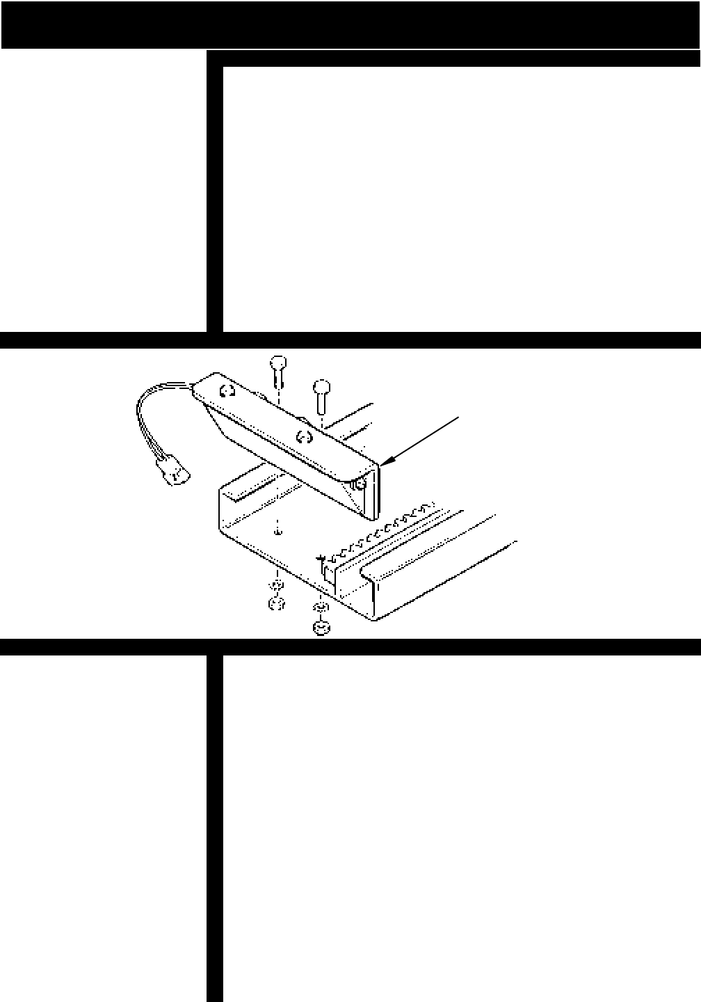
BUMPER BRACKET INSTALLATION
[ ] Assemble lower rail, install Bumper Bracket.
[ ] Determine the correct length for the Rail by measuring
along a straight line placed on the stairs. (SEE STEP 2 IN
THE APPLICATION GUIDE) Add to that amount
measurement B (STEP 4 IN THE APPLICATION GUIDE). This
process will allow you to custom fit the elevator to your
customer taking into consideration the most comfortable
seat to floor height within the space available at the top of
the stairs.
NOTE: THE RAIL MUST REST APPROXIMATELY 1/2" TO 1" ABOVE
NOSING OF THE STEPS AND EXTEND FROM THE LOWER
FLOOR TO A POINT BEYOND THE NOSING OF THE TOP STEP
(SEE APPLICATION GUIDE STEP 4). IN SOME CASES WHERE
THE BOTTOM LANDING IS MADE OF MATERIAL SUCH AS
(CONCRETE, CERAMIC TILE OR SLATE) THE LAST BRACKET ON
THE LANDING MAY BE OMITTED WITH A BRACKET ADDED ON
THE SECOND STEP FROM THE BOTTOM AND TOP OF STAIR-
WAY.
BUMPER BRACKET
CAUTION:
THIS RAIL MUST BE
INSTALLED 1/2" TO 1"
ABOVE NOSING OF
STAIRS, OR THE
FOOTREST WILL HIT
THE STEPS CAUSING
INTERMITTENT
OPERATION.
© 1998 BRUNO INDEPENDENT LIVING AIDS, INC.
7
INSTALLATION
CUTTING THE RAIL
[ ] Use a metal-cutting power-saw or manual hacksaw to cut
the rail to length. Cut off the end of the rail which will be located at
the top of the stairway.
[ ] Use a file or other appropriate tool to de-burr the cut end of
the rail. Soften any sharp edges which might abrade the
insulation from wiring which must be routed to the bumper at the
end of the rail.
[ ] Use a C-clamp to hold the upper Bumper Bracket in place in
the cut end of the rail and use the holes in the Bumper Bracket
as guides to drill mounting holes using “O” size (8.03 MM/.316")
drill bit in the rail.
[ ] Assemble the Rail joint by attaching the Bottom Plate to
Rail with M6 X 20 Flat Head Screws, external-tooth Lock
washers and M6 Hex Nuts. Install the M10 Bolts, M10 internal
tooth Washer and M10 hex nut through the Joint Blocks on both
sides of the Rail. Tighten all bolts securely and make sure screw
heads are flush with the surface of the inside of the Rail.
NOTE:
THE CHAMFERED EDGES OF THE
HOLES MUST FACE "UP" TOWARD
THE BOTTOM OF THE RAIL.
FIGURE 2
FIGURE 3
NOTE:
THE RAIL IS ALWAYS
INSTALLED WITH THE
GEAR RACK TOWARDS
THE CENTER OF THE
STAIRS AND GEAR TEETH
FACING REAR OF UNIT.
RAIL JOINT ASSEMBLY
USE “O” SIZE DRILL
BIT (8.03MM/.316")
© 1998 BRUNO INDEPENDENT LIVING AIDS, INC.
8
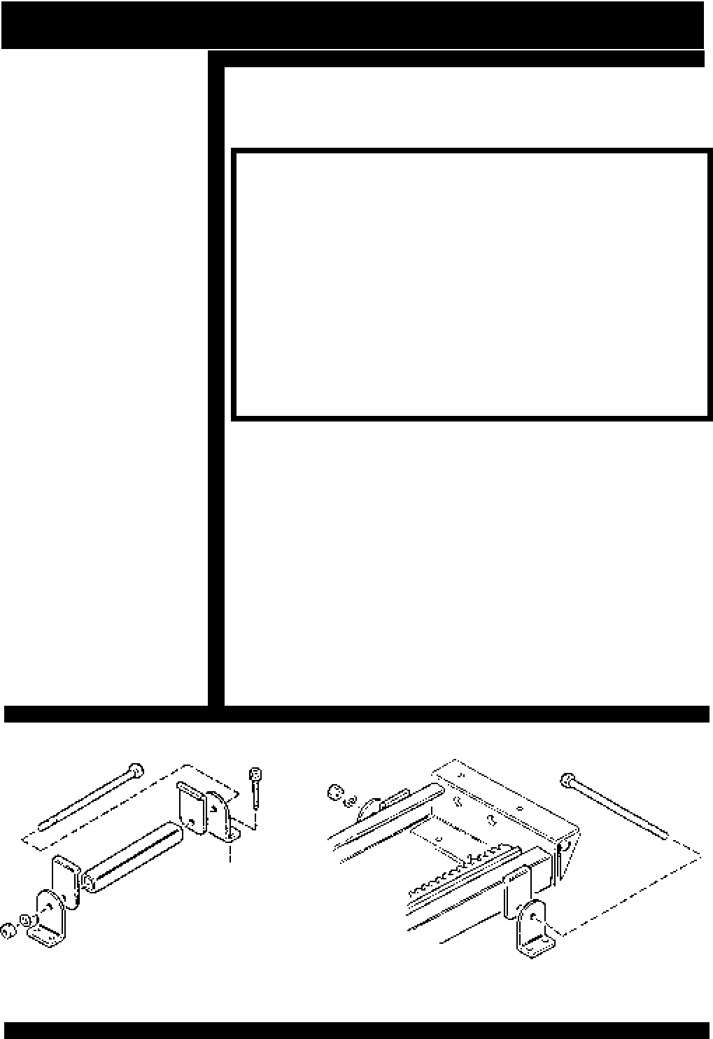
[ ] Install rail mounting foot clamps in the placement pattern
as follows: (leaving a minimum of 1/2" from the wall.)
(See figure 5)
*BOTTOM OF RAIL
*FIRST STEP UP FROM BOTTOM OF RAIL
*TOP STEP OR LANDING
*EVERY OTHER STEP BETWEEN TOP AND BOTTOM
*EXCEPT ONE ON STEPS EACH SIDE OF RAIL JOINT
NOTE: IF TOP OR BOTTOM CLAMP IS OMITTED BECAUSE THE
LANDING IS CEMENT OR CERAMIC TILE OR ANOTHER SUB-
STANCE THAT THE OWNER DOESN'T WANT HOLES IN, A SET
OF CLAMPS SHOULD BE ADDED ON THE SECOND LAST STEP
AND AT THE TOP OF STAIRWAY.
[ ] For ease of installation, finger tighten all clamps to rail.
The clamp assembly should be positioned so the nut is
closest to the wall. (See figure 4 & 5)
[ ] Slide top and bottom clamps down until firmly seated on
step. When installing on carpeted stairs a rubber mallet
should be used on clamps to compress carpet and cushion
before anchoring to steps.
[ ] Install securely one screw near the wall on top and bottom
of foot of clamp assemblies. This will enable the installer
to change position of the rail if necessary and prevent
drilling excess holes.
POSITION RAIL CLAMP ASSEMBLIES
INSTALLATION
FIGURE 4
*NOTE:
CHECK ARM WIDTH
REQUIRED BY
CUSTOMER. IF THE
ARMS ARE ADJUSTED
WIDER THAN
NORMAL, THEN THE
DISTANCE FROM THE
WALL WILL HAVE TO
INCREASE GREATER
THAN 2 1/2" IF
SWIVELING AGAINST
A WALL.
(SEE PAGE 25)
© 1998 BRUNO INDEPENDENT LIVING AIDS, INC.
9
FIGURE 5
*IF SEAT NEEDS TO
SWIVEL AGAINST WALL,
APPROXIMATELY 2 1/2"
FROM WALL,
ADDITIONAL
CLEARANCE WILL BE
NEEDED
CALL/SEND ANTENNA INSTALLATION
RAIL
RAIL MOUNTING FOOT
CLAMP ASSEMBLY
1/2" TO 1"
ABOVE NOSING
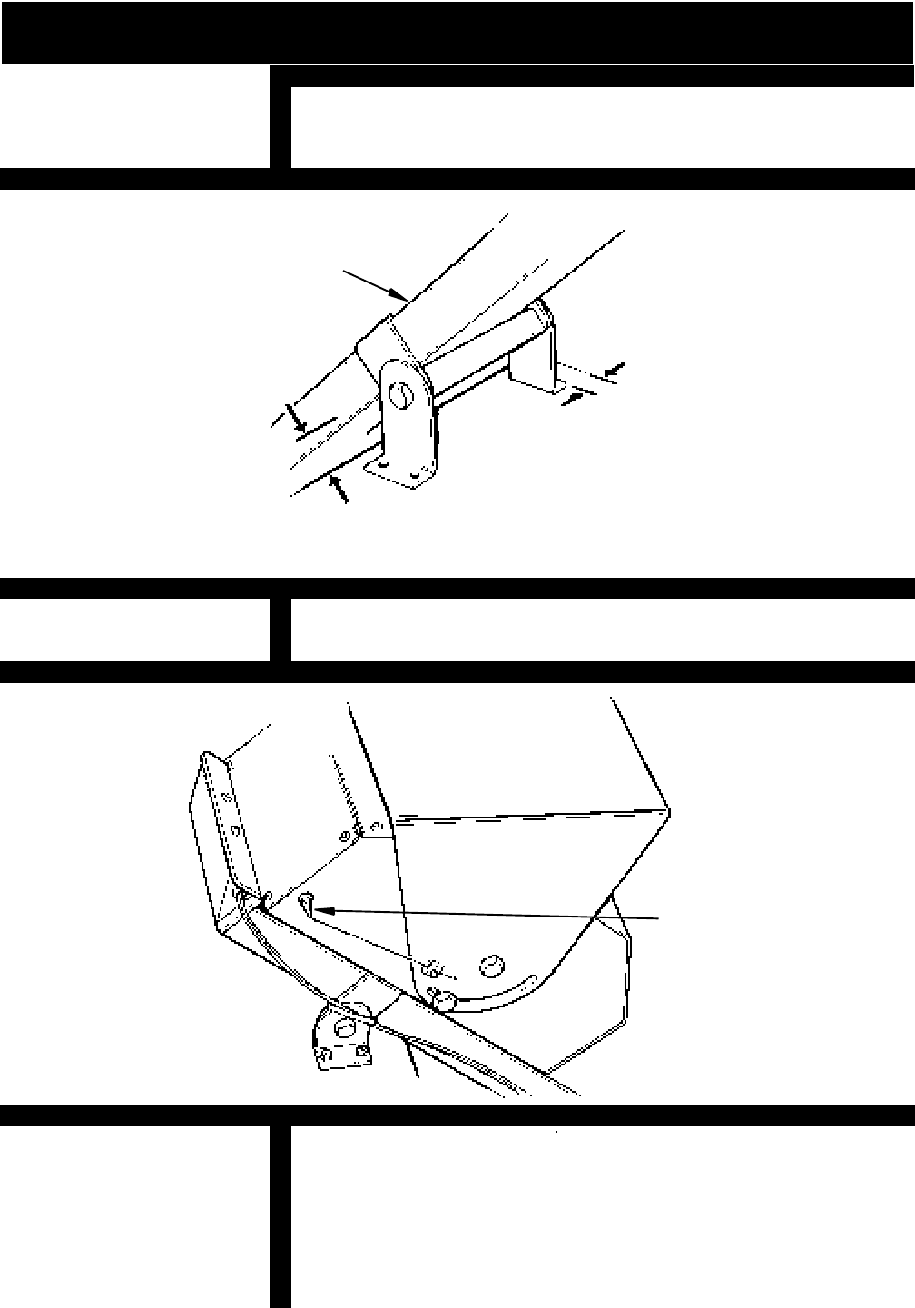
[ ] Install the Call/Send Antenna on the rear side of carriage.
Take care to place the Antenna in a horizontal position.
POSITION RAIL CLAMP ASSEMBLIES
[ ] Make sure to use the measurements in (figure 5) as a guide
for positioning Clamp assemblies.
INSTALLATION
FIGURE 6
*NOTE: IF THE UNIT WILL HAVE TO SWIVEL
AGAINST A WALL AT EITHER END
OF THE RAIL, ADDITIONAL DISTANCE
WILL BE NEEDED BETWEEN THE RAIL
AND THE WALL. CHECK CLEARANCES
BEFORE SECURING TO STAIRS.
CALL/SEND
ANTENNA
© 1998 BRUNO INDEPENDENT LIVING AIDS, INC.
10
[ ] Turn Toggle Switch off. When facing front of unit, remove
left motor cover. Slide the carriage into the Rail until the
spur gear rests on the gear rack. Manually turn the
motor pulley to fully engage the entire carriage inside the
upper rail.
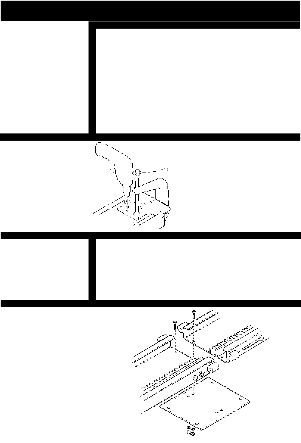
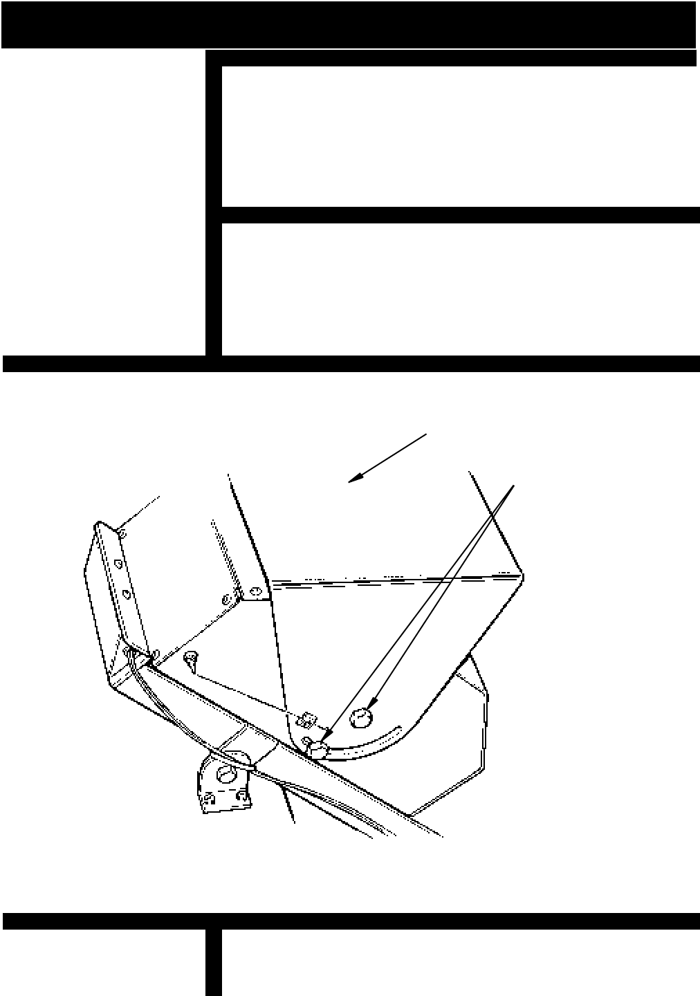
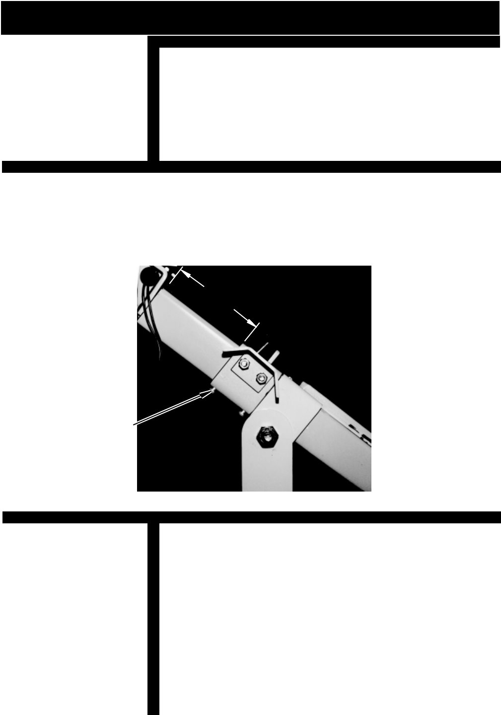
[ ] Adjust the carriage angle by loosening the Angle Adjust-
ment Bolts (shown in figure 7). Level the Angle Adjustment
Bracket, using a standard builders level or protractor level.
When the Angle Adjustment Bracket is level securely
tighten all four Angle Adjustment Bolts*.
INSTALLATION
MOUNT THE CARRIAGE ON THE UPPER RAIL
FIGURE 7
ADJUST THE CARRIAGE ANGLE
ANGLE ADJUSTMENT
BRACKET
ANGLE ADJUSTMENT
BOLTS
NOTE:
*RECHECK WITH LEVEL
AFTER TIGHTENING
ADJUSTMENT BOLTS.
© 1998 BRUNO INDEPENDENT LIVING AIDS, INC.
11
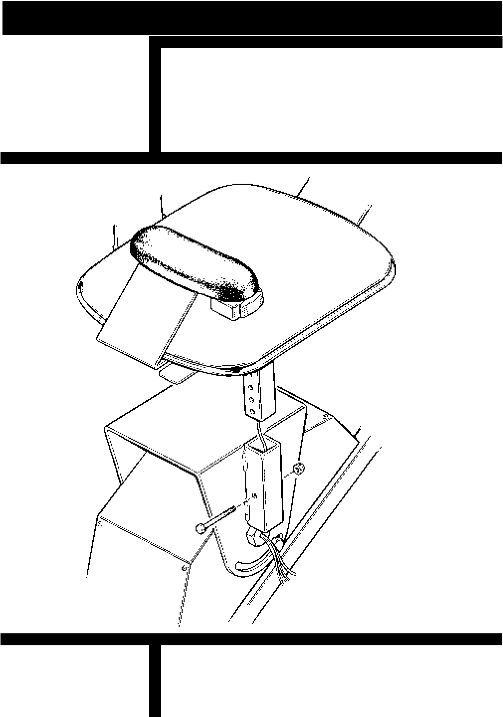
[ ] Feed the five conductor lead through the hollow tube
under the seat. Insert seat frame post into the outer
mounting tube. Determine the correct seat height then
insert bolt in desired hole leaving the head of the bolt
protruding 3/8" from the mounting tube. (As shown in
figure 9). Fish excess wires into hole on Front Pivot Bolt.
[ ] Remove Footrest Assembly, then gently pull extra wire
from hole in Pivot Bolt. Then remove bolt in seat adjust-
ment tube weldment. Adjust seat height, replace bolt and
secure. Reinsert extra wire in Pivot Bolt, replace Footrest
Assembly.
INSTALL SEAT ASSEMBLY
FIGURE 8
INSTALL SEAT ASSEMBLY AS SHOWN
INSTALLATION
SEAT HEIGHT ADJUSTMENT
FRONT PIVOT BOLT
© 1998 BRUNO INDEPENDENT LIVING AIDS, INC.
12
OUTER MOUNTING
TUBE
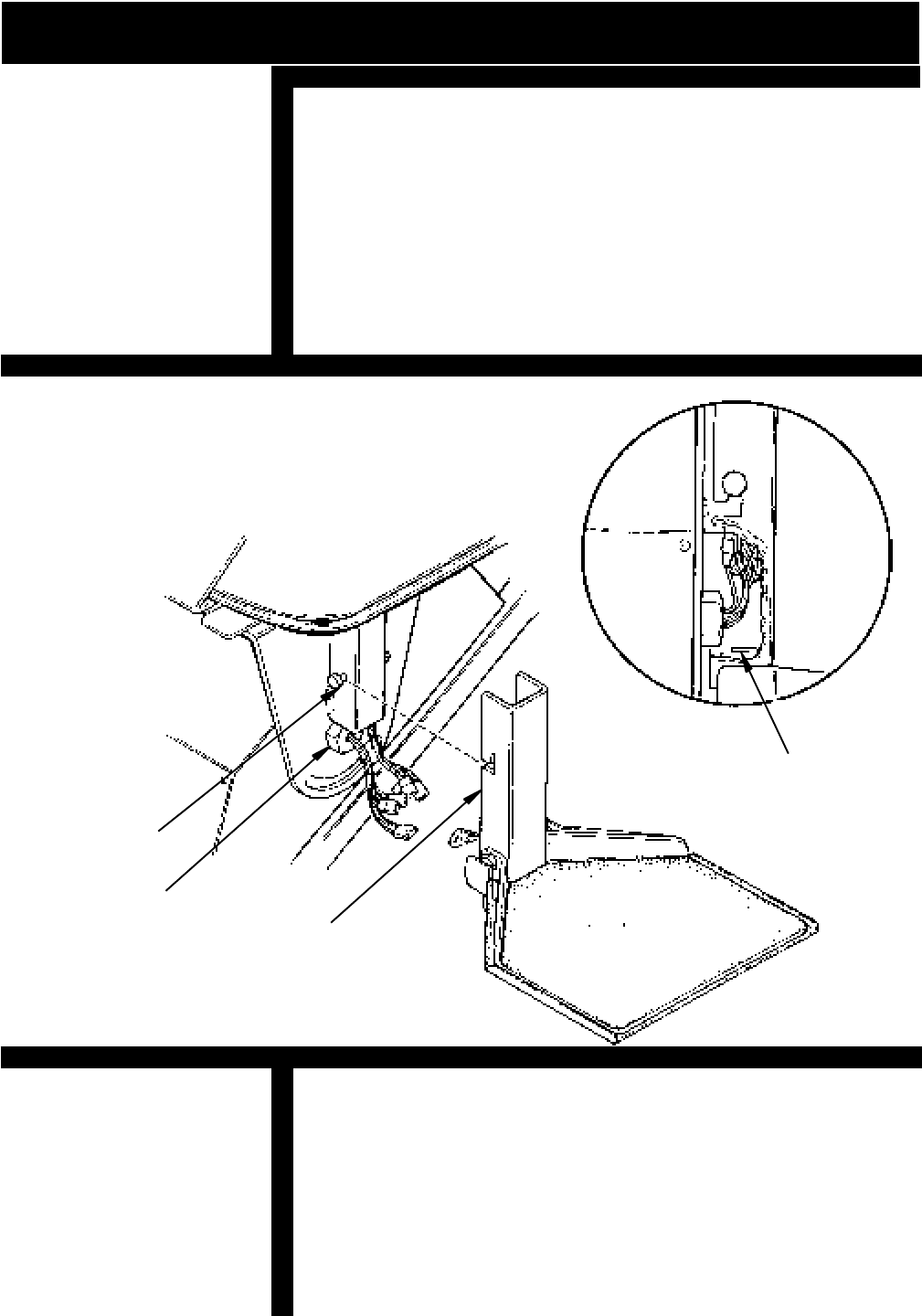
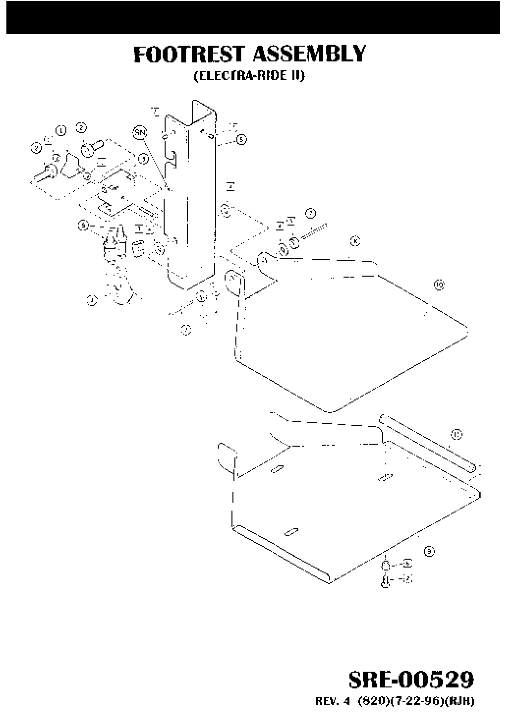
FOOTREST ASSEMBLY
FIGURE 9
INSTALLATION
Connect the wires as shown in illustration (See figure 9). Tuck
excess wires in Outer Mounting Tube just below the bolt in Seat
Adjustment Tube. While holding the wires in place bring the
footrest close to the carriage near the Pivot Bolt, tilt the Footrest
slightly while raising it up and over the Bolt until it is engaged in
the slot.
NOTE: BE CAREFUL NOT TO PINCH THE WIRES WHILE
SLIDING THE FOOTREST OVER THE BOLT.
[ ] With the seat in the central riding position, move the
elevator completely down and up the rail, while
observing the elevator to wall clearance. A clearance of
1/2" to 1" is acceptable. Repeat the run with the seat
in the folded position. If necessary, adjust the rail
placement by sliding it closer or further from the wall.
[ ] Test the unit for proper: speed, direction, Limit Switch
operation, Footrest Safety Switch operation, Seat
Swivel Safety Switch operation and Remote Call/Send
operation.
PIVOT BOLT
FOOTREST HANGER
FOOTREST SWITCH
BRACKET
ELECTRA-RIDE II TRIAL RUN
© 1998 BRUNO INDEPENDENT LIVING AIDS, INC.
13
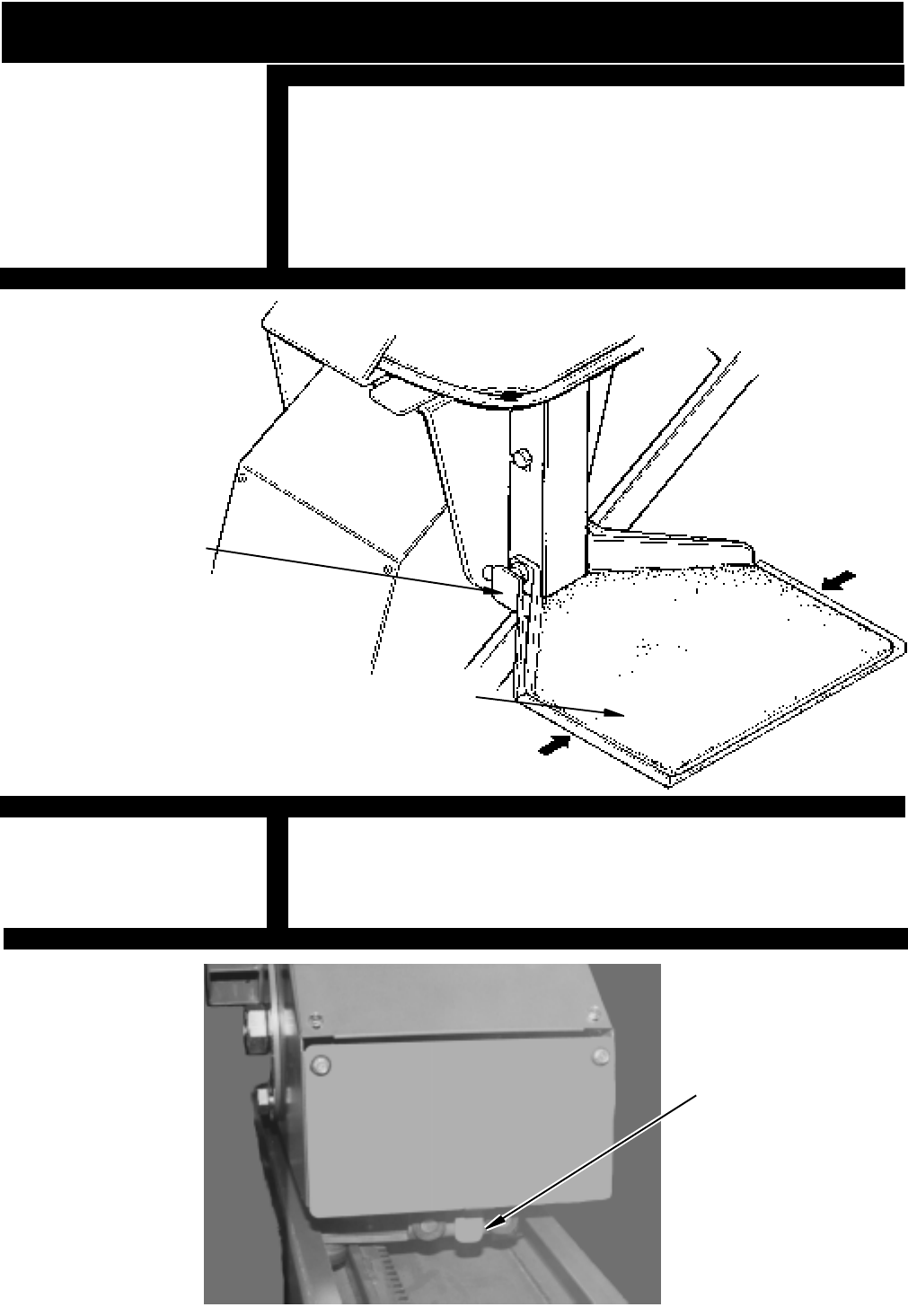
[ ] The footrest comes equipped with a safety switch which
will stop the elevator in the event that something becomes
trapped between the footrest and a stair tread. Confirm
correct operation of this feature by moving the sliding tray
(BOTH SIDES) while operating the elevator. The elevator
will stop if this feature is operating correctly.
The Carriage comes equipped with a Safety Switch Panel.
As the Carriage approaches the end of the Rail, the Panel is
depressed, which activates the Switch, and stops the carriage.
FIGURE 10
INSTALLATION
SAFETY SWITCH
FOOTREST
SAFETY SWITCH
NOTE:
MAKE SURE
CALL/SEND ANTENNA
HAS CLEARANCE FOR
ENTIRE TRAVEL OF
RAIL.
SAFETY
SWITCH PANEL
FIGURE 11
SAFETY SWITCH PANEL
© 1998 BRUNO INDEPENDENT LIVING AIDS, INC.
14
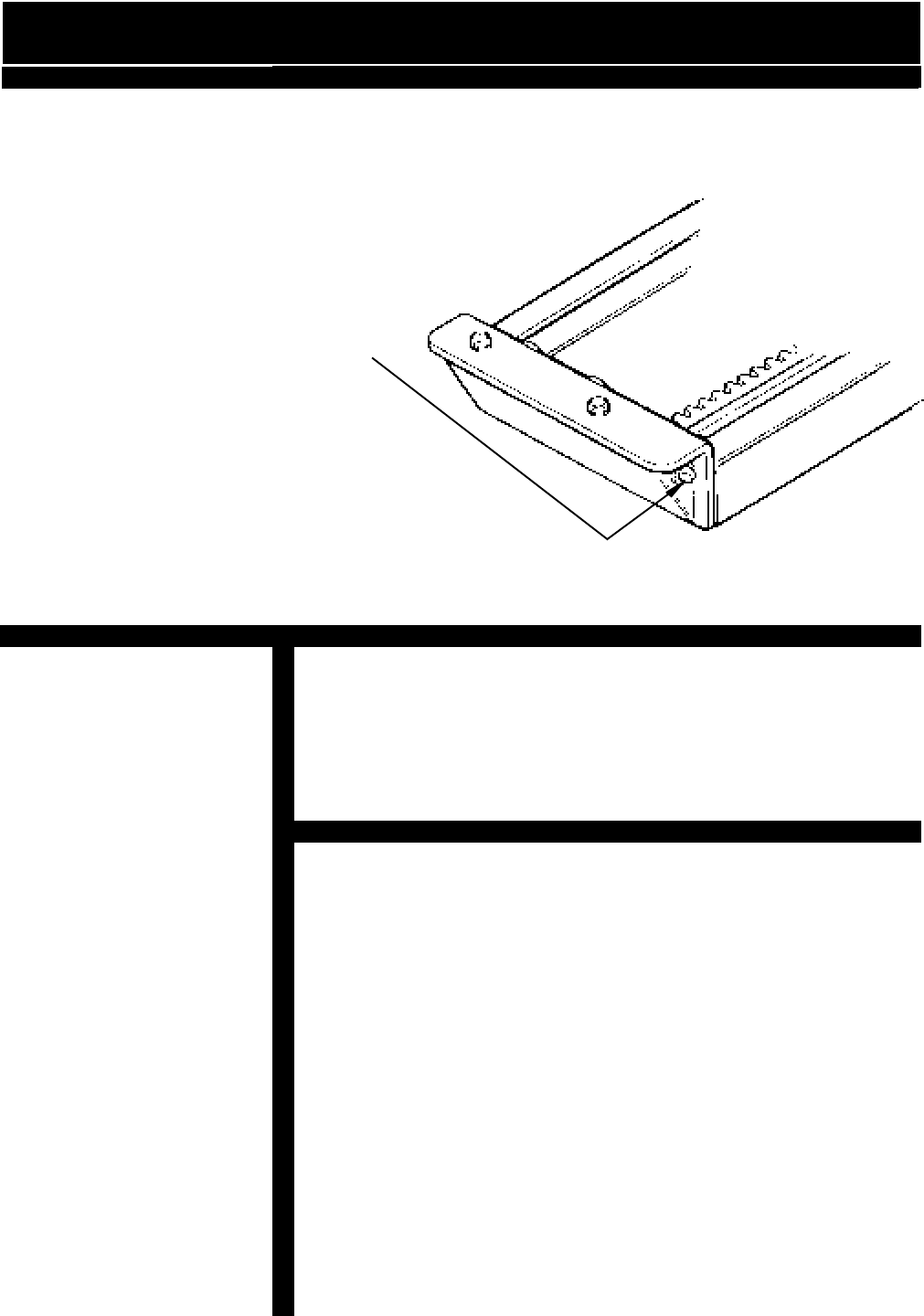
The Final Limit Switch and Actuation Ramp is an added safety
feature for stopping the unit. The Actuation Ramp is to be
mounted to the side of the rail 1" from the top of the rail in a LEFT
HAND installation. In a RIGHT HAND installation the Actuation
Ramp is to be mounted 8" from the top end of the rail. Tighten M5
X .8 Hex Head Screws on bottom of ramp.
INSTALLATION OF FINAL LIMIT ACTUATION
RAMP
TIGHTEN M5 X .8 HEX
HEAD CAP SCREWS
FIGURE 12
MEASURE THE
DISTANCE FROM THE
END OF THE RAIL TO
THE INSIDE EDGE OF
THE ACTUATION RAMP
1" LH
8" RH
© 1998 BRUNO INDEPENDENT LIVING AIDS, INC.
15
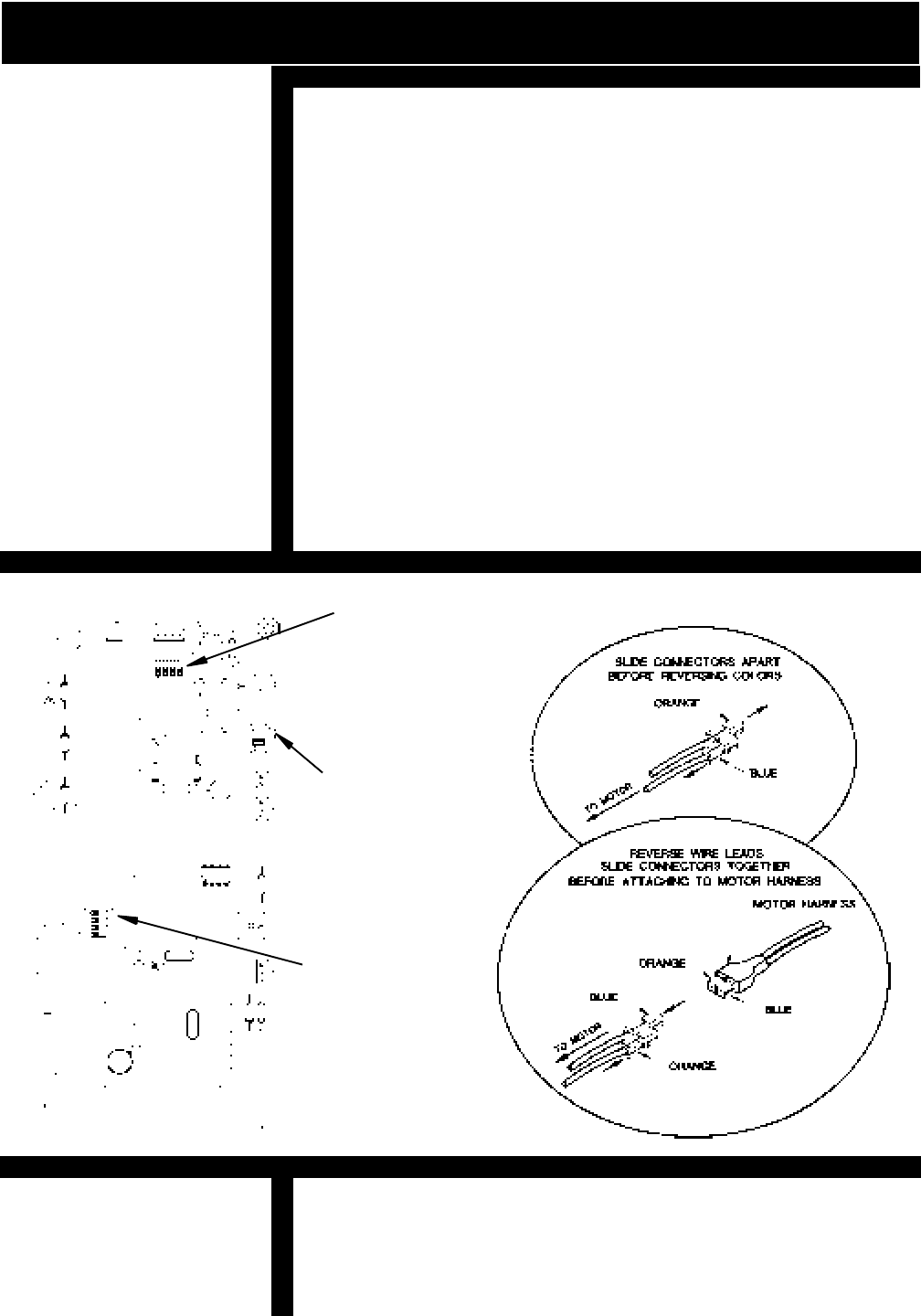
[ ] The elevator is shipped set up for a left side installation (on
your left as you view the elevator from the bottom of the
stairs.) Should the installation require a right hand
installation observe the following instructions.
[ ]
Turn the On / Off Circuit Breaker on the rear of carriage to
`OFF'.
[ ] Remove Left Carriage Cover.
[ ] Set the Installation DIP Switch (S2) to the `RH' position.
[ ] Set the No. 1 DIP Switch on the 4-Ganged Dip Switch
(SW1) to the `OFF' position.
[ ] Check that the Power Switch (S3) is turned `ON' .
[ ] Unplug the Motor Leads and reverse connections.
[ ] Turn the Circuit Breaker Switch to the “ON” position.
[ ] Replace the Carriage Cover.
[ ] Remove the Switch Housing weldment by removing the
phillips head machine screw under the arm. The
trim holding the harness on the backside of the arm slides
off. Disconnect the harness under the seat and route the
harness through the opposite side. Fasten the switch hous-
ing on the left arm and reconnect the harness. Slide the
trim over the harness on the backside of the arm.
REVERSING OPERATION
INSTALLATION ON RIGHT SIDE OF STAIRWAY
FIGURE 13
CHANGING CONTROLS FROM RIGHT TO LEFT ARMREST
CHANGING CONTROLS FROM RIGHT TO LEFT ARMREST
FLIP THE
INSTALLATION
DIP SWITCH
FROM `LH' TO
`RH' POSITION
FLIP NO. 1
SWITCH
TO THE `OFF'
POSITION
REVERSING CONNECTIONS
CIRCUIT BOARD
POWER DIP
SWITCH S3

© 1998 BRUNO INDEPENDENT LIVING AIDS, INC.
16
The Interconnect Circuit Board provided on the (1550) unit is
equipped with diagnostic modes that will continuously monitor the
operation of the lift. The Circuit Board has four available diagnos-
tic modes to accommodate all types of installations.
(The elevator is shipped in Mode #1)
Provides full range of Audio diagnostic notices:
* Circuit Board Power Up : Chirp
* Safety Device Activated: Chirp
* Stairlift Stopped off Charge Bumper: 5 Beeps (4 short and 1
long) Repeats every 3 minutes until stairlift is returned to
bumper.
* Battery Voltage Drop : 5 Beeps (3 short and 2 long) Repeats
every 4 minutes until seat safety switch is disengaged, the
battery voltage increases or switch is pressed.
* Battery Voltage Critical: 5 Beeps (2 short and 3 long)
Repeats once a minute until voltage is above 16 V or switch is
pressed.
* Switch is active during Power Up: 2 Beeps / Pause Repeats
beeps every 5 seconds until all switches are off.
* More than one switch active: 2 Beeps / Pause Repeats every
30 seconds until all switches are off.
Provides the same audio diagnostic notices as Mode # 1 except
for the Seat Safety Disengaged notice. The unit will chirp one
time and not repeat the notice.
In the quiet mode none of the Audible Warning Messages are
active.
Provides battery audio diagnostic only.
* Stairlift Stopped off Charge Bumper: 5 Beeps (4 short and 1
long) Repeats every 3 minutes until stairlift is returned to
bumper.
* Battery Voltage Drop : 5 Beeps (3 short and 2 long) Repeats
once every 4 minutes until seat safety switch is disengaged or
the battery voltage increases.
* Battery Voltage Critical: 5 Beeps (2 short and 3 long)
Repeats once a minute until voltage is above 16 V.
CIRCUIT BOARD OPERATION
MODE # 1 MULTI - USER / DIAGNOSTIC MODE
MODE # 2 SINGLE - USER
MODE # 3 QUIET
MODE # 4 BATTERY WARNINGS ONLY
© 1998 BRUNO INDEPENDENT LIVING AIDS, INC.
17
Chirp .25 Seconds
Short Beep .5 Seconds
Long Beep 1.5 Seconds
Pause 1 Second
CIRCUIT BOARD OPERATION
AUDIO REFERENCE
CHANGING THE PCB DIAGNOSTIC MODE
* Turn the Circuit Breaker on the carriage to `OFF'.
* Remove Left carriage cover.
* Turn the Power DIP Switch (SW3) to the `OFF' position.
* Unit is shipped is Multi-User diagnostic Mode # 1.
Changes are made on (S1) 4 Ganged DIP Switch -
Number 3 and Number 4 Positions.
Also located on S1 DIP Switch are switch #1 Installation and
#2 Coast Delay. Refer to page 15 (Reversing operation) for
changing Switch # 1. The coast delay option (Switch #2 on
S1) has been provided in cases of interference which may
cause intermittent operation. The normal setting is 1.5 sec-
onds of coast, should the unit lose the remote call/send signal,
this can be increased to 2.0 seconds by moving switch # 2 on
S1 to the `ON' position.
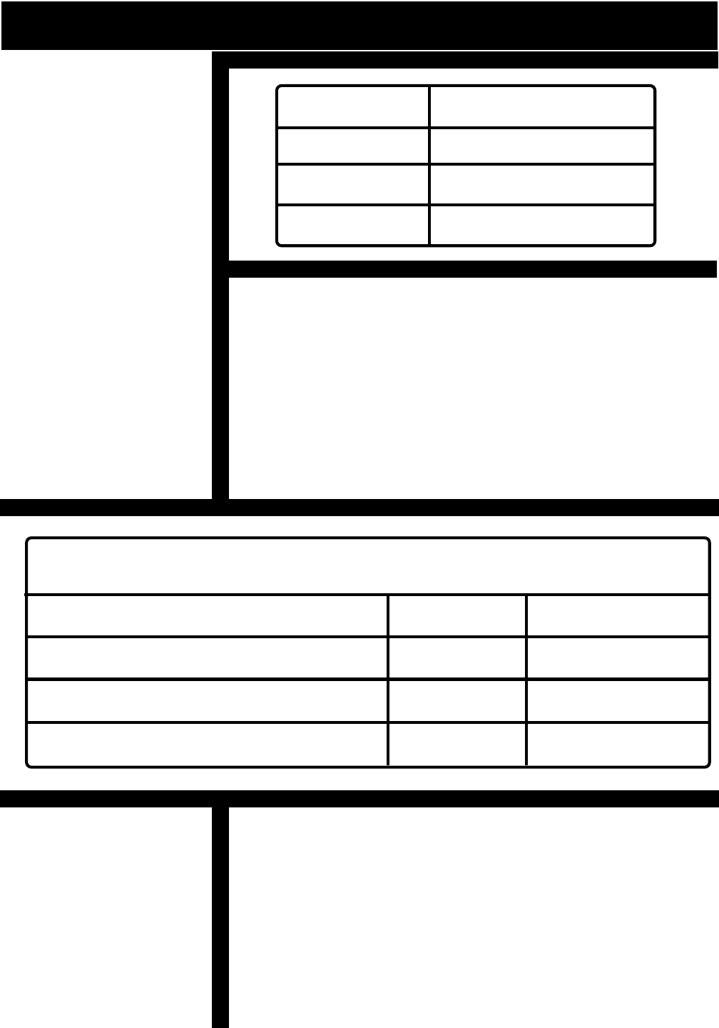
4 GANGED DIP SWITCH (SW1)
DIAGNOSTIC MODE DIP SWITCH POSITION
#3 #4
Mode # 1 - Multi-User OFF OFF
Mode # 2 - Single-User OFF ON
Mode # 3 - Quiet ON OFF
Mode # 4 - Battery Warning Only ON ON
OTHER CIRCUIT BOARD FEATURES
© 1998 BRUNO INDEPENDENT LIVING AIDS, INC.
18 INSTALLATION
INSTALL FOOT CLAMPS
RECHECK NOTE:
BEFORE TIGHTENING
THE BRACKETS
CHECK TO MAKE
SURE THAT THE
BUMPER WIRES ARE
NOT TRAPPED UNDER
BUMPER BRACKET AT
LOWER LANDING
NOTE:
IF THREADED FASTENER
EXTENDS BELOW A
STAIR TREAD THAT IS
EXPOSED, IT CAN BE
TRIMMED FLUSH WITH A
PLIERS.
[ ] Check that the foot clamp base position is a minimum of
1/2" from the wall.
NOTE: THE STAIRWAY ELEVATOR COMES
WITH FASTENERS APPROPRIATE FOR WOODEN
STAIR TREADS ONLY. OTHER STAIR MATERIAL
MAY REQUIRE DIFFERENT FASTENERS (CONTACT
BRUNO INDEPENDENT LIVING AIDS FOR FURTHER
ASSISTANCE). (NOTE: FOR HARDWOOD STAIRS, IT IS
RECOMMENDED THAT A PILOT HOLE BE DRILLED
BEFORE SCREWING IN FASTENERS).
[ ] Once rail position is confirmed, place one screw in each
bracket to hold rail in place while tightening to rail.
(This will prevent mounting feet from rotating while bolt is
being tightened.)
[ ] Tighten rail bolt and install the rest of the screws in
bracket, then tighten securely.
[ ] Install the upper bumper bracket to rail.
INSTALL THE UPPER BUMPER BRACKET
FIGURE 14
© 1998 BRUNO INDEPENDENT LIVING AIDS, INC.
19
[ ] Install the upper bumper bracket to rail.
[ ] Apply a coating of White *Lithium Grease to the
Gear Rack and inner flanges of the Stair Rail as shown.
1 TUBES PER 16 FOOT UNIT
2 TUBES PER 20 FOOT UNIT
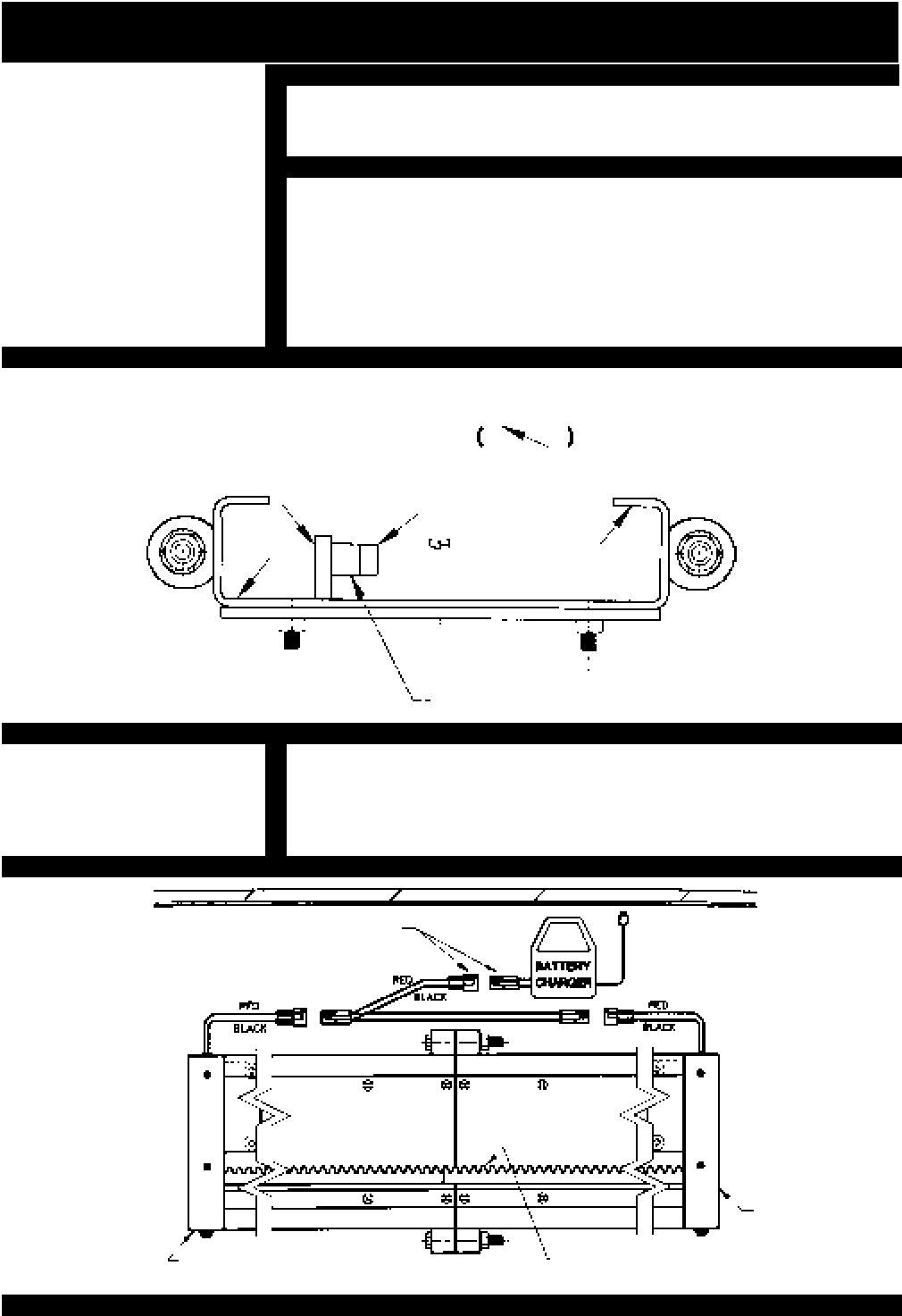
[ ] Position the Charger in a suitable permanent location.
[ ] Install the wiring harness on the Elevator Rail and
connect to the Charger as shown.
INSTALL THE UPPER BUMPER BRACKET
CHARGER/RAIL LEAD APPLICATION
FIGURE 16
FIGURE 15
LUBRICATION
INSTALLATION
NOTE: GEAR RACK TEETH
FACE WALL OF STAIRWAY
RAIL BUMPER
RED CONNECTORS WALL
APPLY A LIGHT COATING OF WHITE
LITHIUM GREASE TO THESE SURFACE
LIGHT .
GEAR RACK
© 1998 BRUNO INDEPENDENT LIVING AIDS, INC.
20
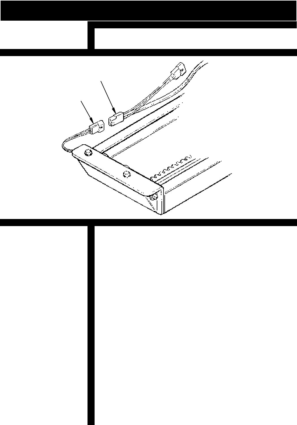
[ ] Make the connections to the Charger Wiring Harness.
[ ] Route the Charger Wiring Harness along the back side
of the Rail and secure it to the Rail Mounting Clamps
with wire ties. Be sure that this wiring is mounted
securely so that it is not vulnerable to physical damage.
[ ] Coil any excess harness wire and attach to a Rail Clamp
(under the rail).
NOTE: THE CHARGER SHOULD BE PLUGGED INTO A
HOUSEHOLD OUTLET ALL OF THE TIME. THE ELEVATOR IS
DESIGNED SO THAT THE BATTERIES WILL BE CHARGED
WHEN THE CARRIAGE IS AT ONE OR THE OTHER END OF
THE RAIL. IT IS IMPERATIVE THAT THE CARRIAGE BE
"PARKED" AT THE END OF THE RAIL WHEN IT IS NOT IN USE
TO MAINTAIN FULL BATTERY CHARGE.
IN AN INSTALLATION WHERE THE CARRIAGE CAN NOT BE
PARKED AT THE END OF THE RAIL (STAIRWAYS WITH A
DOOR AT THE TOP, FOR EXAMPLE), THE CARRIAGE
SHOULD BE RUN TO THE OTHER END OF THE RAIL WITH
THE REMOTE CALL/SEND MODULE WHEN NOT IN USE.
THIS WILL ENSURE THAT THE BATTERIES WILL REMAIN
FULLY CHARGED.
FIGURE 17
SUGGESTION:
AFTER ROUTING THE
WIRE HARNESS OUT OF
SIGHT A SMALL PIECE
OF DOUBLE SIDED
FOAM TAPE CAN BE
APPLIED TO THE
HARNESS PLUGS AND
ATTACH UNDER THE
RAIL.
NOTE:
IF CHARGER PLUG AND
WIRE ARE LOCATED IN
A VULNERABLE
LOCATION, A PLUG
LOCK TO PREVENT
ACCIDENTAL
UNPLUGGING IS
RECOMMENDED.
THESE ARE AVAILABLE
AT HARDWARE AND
DEPARTMENT STORES.
RAIL CHARGER LEAD
LEAD TO BATTERY
CHARGER WIRING
HARNESS
ROUTING WIRE HARNESSES
INSTALLATION
© 1998 BRUNO INDEPENDENT LIVING AIDS, INC.
21
INSTALLATION / REMOTE CALL/SEND
MOUNTING THE CALL/SEND MODULES
THE UNITS CAN BE MOUNTED TO A WALL WITH THE
ADHESIVE-BACKED VELCRO PROVIDED. THE CALL SEND
MODULE SHOULD BE MOUNTED SO OPERATOR CAN
ALWAYS VIEW THE ELEVATOR AND OUT OF REACH OF
CHILDREN.
TESTING THE UNIT
A SLIGHT DELAY WILL OCCUR BETWEEN THE TIME THE
ROCKER SWITCH IS DEPRESSED AND THE INITIATION OF
CARRIAGE MOVEMENT. THIS IS NORMAL AND IS A
FUNCTION OF THE SOFT START FEATURE OF THE
CONTROLLER.
[ ] Run the unit up and down the stairs with the Rocker
Switch on the Carriage. The unit should operate in such
a way that the Rocker Switch is depressed in the
desired direction of travel.
The unit should travel noticeably faster going up than down.
[ ] Run the unit up and down the stairs with the Remote
Call/Send modules. Test both Modules.
[ ] Fold the seat into the stored position and run the unit up
and down the stairs with the Remote Call/Send Module.
FIGURE 18
ALWAYS "PARK" THE CARRIAGE AT THE UPPER
OR LOWER END OF THE RAIL TO KEEP BATTERIES
FULLY CHARGED
PILOT LAMP INDICATES
"CHARGING CONTACT" AND
CORRECT POLARITY.
BE SURE CHARGER IS
PLUGGED INTO A "LIVE"
OUTLET.
© 1998 BRUNO INDEPENDENT LIVING AIDS, INC.
22 CALL/SEND CODE
TRANSMITTER BATTERY REPLACEMENT
LOOSEN 4 PHILLIPS SCREWS THEN REMOVE BACK OF
TRANSMITTER FOR BATTERY REPLACEMENT
NOTE:
WHILE USING THE
REMOTE CALL SEND,
SOME INTERMITTENCE
MAY BE EXPERIENCED.
IT MAY BE A MINOR
INCONVENIENCE, BUT IN
NO WAY HARMS OR
IMPAIRS THE UNIT. YOU
SHOULD EXPERIENCE
NO INTERRUPTION
WHILE USING ROCKER
SWITCH.
NOTE:
RADIO INTERFERENCE
CAN OCCUR IF MORE
THAN ONE RADIO
CONTROL
(OR OTHER RADIO
DEVICE ) IS OPERAT-
ING
ON THE SAME
FREQUENCY. THIS
COULD CAUSE THE
SRE-1550 CALL / SEND
FUNCTION TO NOT
WORK
PROPERLY. FOR BEST
PERFORMANCE, MAIN-
TAIN A DISTANCE
FROM
RADIO CONTROL
DEVICES ON THE SAME
FREQUENCY. RADIO
INTERFERENCE CAN
ALSO OCCUR NEAR
HIGH
VOLTAGE ELECTRICAL
WIRES, REINFORCED
CONCRETE BUILDINGS
OR CB RADIOS.
INTERFERENCE MAY
BE LESSENED OR
ELIMINATED BY
SETTING THE INTER-
CONNECT BOARD
DELAY FROM 600mS TO
900mS. THIS IS EASILY
DONE BY MOVING
SWITCH #1 TO
POSITION 2
TRANSMITTER
THREE AAA
BATTERIES
NEEDED FOR
TRANSMITTER
[ 1] Your unit comes with 2 remote controls learned.
[ 2] Should you need to add a remote or replace a remote follow
these instructions.
[ 3] Locate Learn/Erase LED and switch (S4).
[4 ] While holding down Learn/Erase switch with LED on, press
remote control switch (up or down) until LED goes out. This
remote is now `learned'. Repeat this process with all other
remote controls, you may `learn' up to 4 transmitters per unit.
[ 5] When a replacement transmitter is needed, the
memory must be cleared and all transmitters must be
`relearned'.
[ ] To clear memory hold down Learn/Erase switch S4 until LED
goes out (approximately 12 seconds)
[ ] Learn new transmitter(s) to receiver.
LEARN TRANSMITTER TO RECEIVER
HOW TO CLEAR MEMORY
NOTE:
CALL SENDS ARE
SHIPPED WITH THE
BATTERIES
REMOVED.
© 1998 BRUNO INDEPENDENT LIVING AIDS, INC.
23
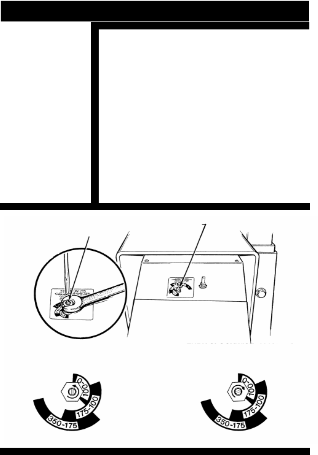
SPEED ADJUSTMENT
A provision for adjusting speed is one of the unique features of the
SRE-1550 Stairway Elevator. The Speed Adjustment
Potentiometer is located on the top of the Carriage and can be
adjusted by following this procedure:
[ ] Loosen the Collet Nut on the Speed Control Potentiom-
eter approximately one-half turn.
[ ] Turn the Potentiometer all the way counterclockwise this is
the starting point. Turn the Potentiometer clockwise
aligning the slotted shaft with the weight range of the user.
[ ] The speed may be adjusted by turning the slotted shaft on
the Potentiometer (clockwise = faster, counterclockwise =
slower). With the customer on the unit make several test
runs to arrive at the most to appropriate speed setting.
[ ] When the speed has been set satisfactorily, retighten the
collet nut. (Recheck speed)
SPEED ADJUSTMENT
POTENTIOMETER COLLET NUT
FIGURE 20
TURN CLOCKWISE, ALIGNING
SLOTTED SHAFT WITH WEIGHT
RANGE OF CUSTOMER
TURN POTENTIOMETER
COUNTERCLOCKWISE THEN
© 1998 BRUNO INDEPENDENT LIVING AIDS, INC.
24
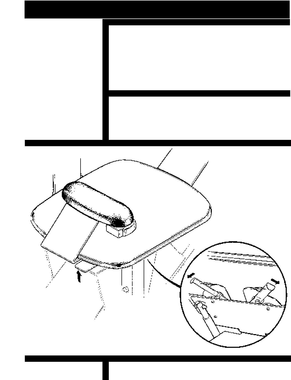
PUSH UP LATCH
TO SWIVEL SEAT
Fold the seat up when not in use, the seat latch will
automatically keep the seat folded until ready to use. To
use the elevator, the rider can push down the seat, or push
down on the arm rest to unfold the seat for easy transfer.
There is a swivel latch directly under the seat which will rotate the
seat every 45 degrees. To disengage the latch lift up on the lever
either on the right or left front edge of the seat. To lock the seat in
place release the lever.
Push the arm lock lever to rotate the arm up to 90 degrees for
easy transfer. The arm then can be rotated back to its original
position, the arm is locked in place when the latch engages auto-
matically.
SEAT LATCH AND ARM LOCK
FIGURE 21
ARM RELEASE
SEAT LATCH
© 1998 BRUNO INDEPENDENT LIVING AIDS, INC.
25
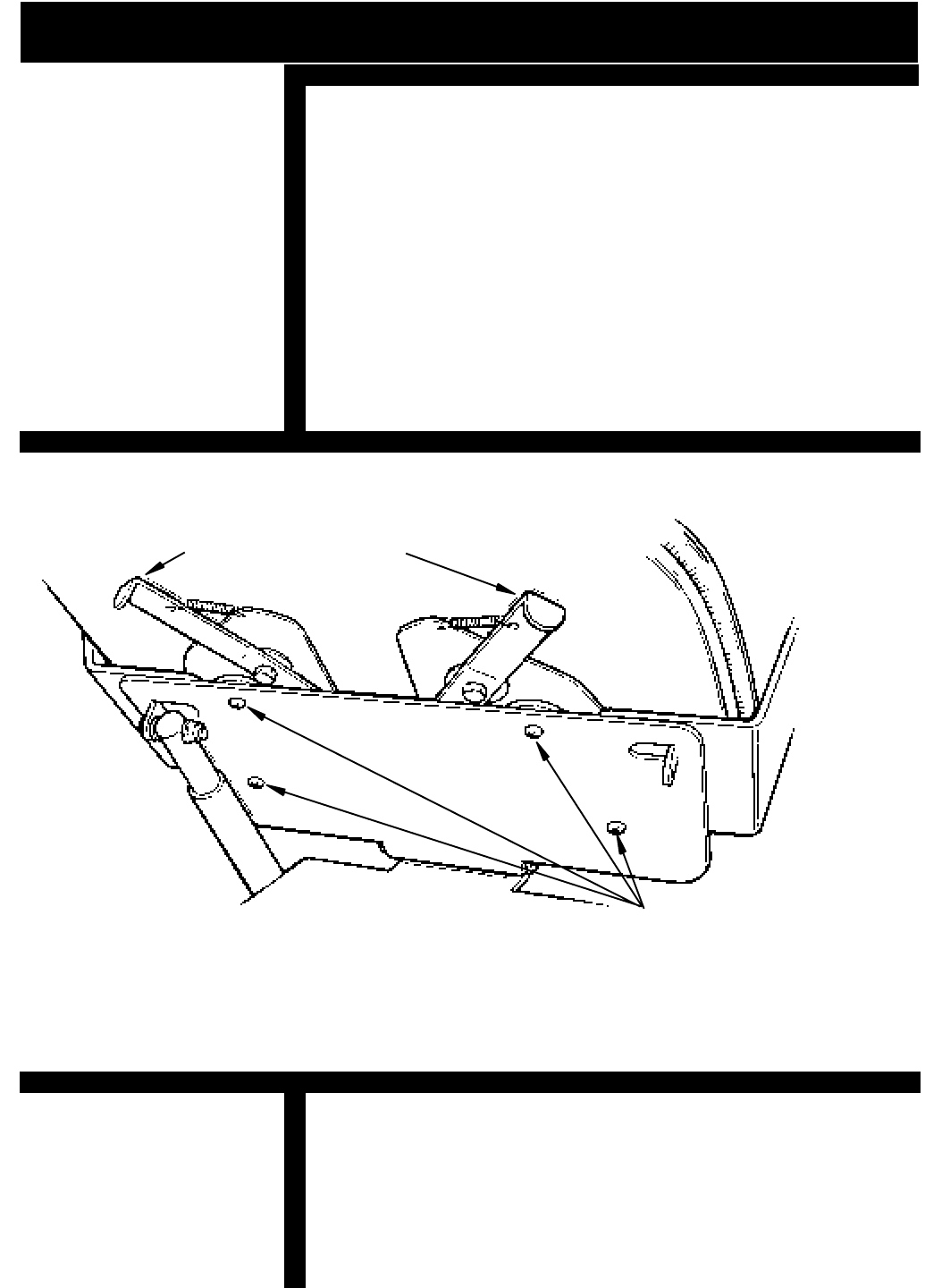
FIGURE 22
SEAT WIDTH ADJUSTMENT
The seat is set at its narrowest position. To adjust the seat at a
wider setting, loosen the phillips head screws on the bottom of
the seat shown in the illustration. Rotate arm out to desired
position. Secure screws and repeat process on other side.
NOTE:
IF THE ARMS NEED TO BE EXTENDED TO THE WIDEST
POINT, THE DISTANCE THE RAIL SHOULD BE
INSTALLED NEAR THE WALL WILL NEED TO BE AD-
JUSTED TO COMPENSATE FOR ROTATING OF THE
WIDER SEAT.
ARM ADJUSTMENT SCREWS
SEAT ADJUSTMENT
ARM LOCK RELEASE
© 1998 BRUNO INDEPENDENT LIVING AIDS, INC.
26
A Circuit Breaker is built into the on/off switch and is provided to
protect the Battery / Controller / Motor circuits in the Elevator
Carriage. It is unlikely that this Circuit Breaker will ever “trip” in
normal use, but if the Elevator should fail to operate, check the
Circuit Breaker and reset it if necessary. If the Circuit Breaker
should trip, determine the cause and correct the situation.
The most likely cause of a tripped Circuit Breaker would be a
foreign object jamming the Rail or Gear Rack or overloading the
elevator by exceeding its rated load capacity.
A Fuse has been provided to protect the Battery Charging circuit
and the Call / Send electronics. The Elevator is shipped with this
Fuse installed.
[ ] Turn “OFF” the unit using the “ON” / “OFF” switch on the back
of the unit.
[ ] Disconnect the Battery Charger from the Rail Charge
Lead.
[ ] Remove carriage cover.
[ ] Determine and repair any short circuit which may have
caused the fuse to blow.
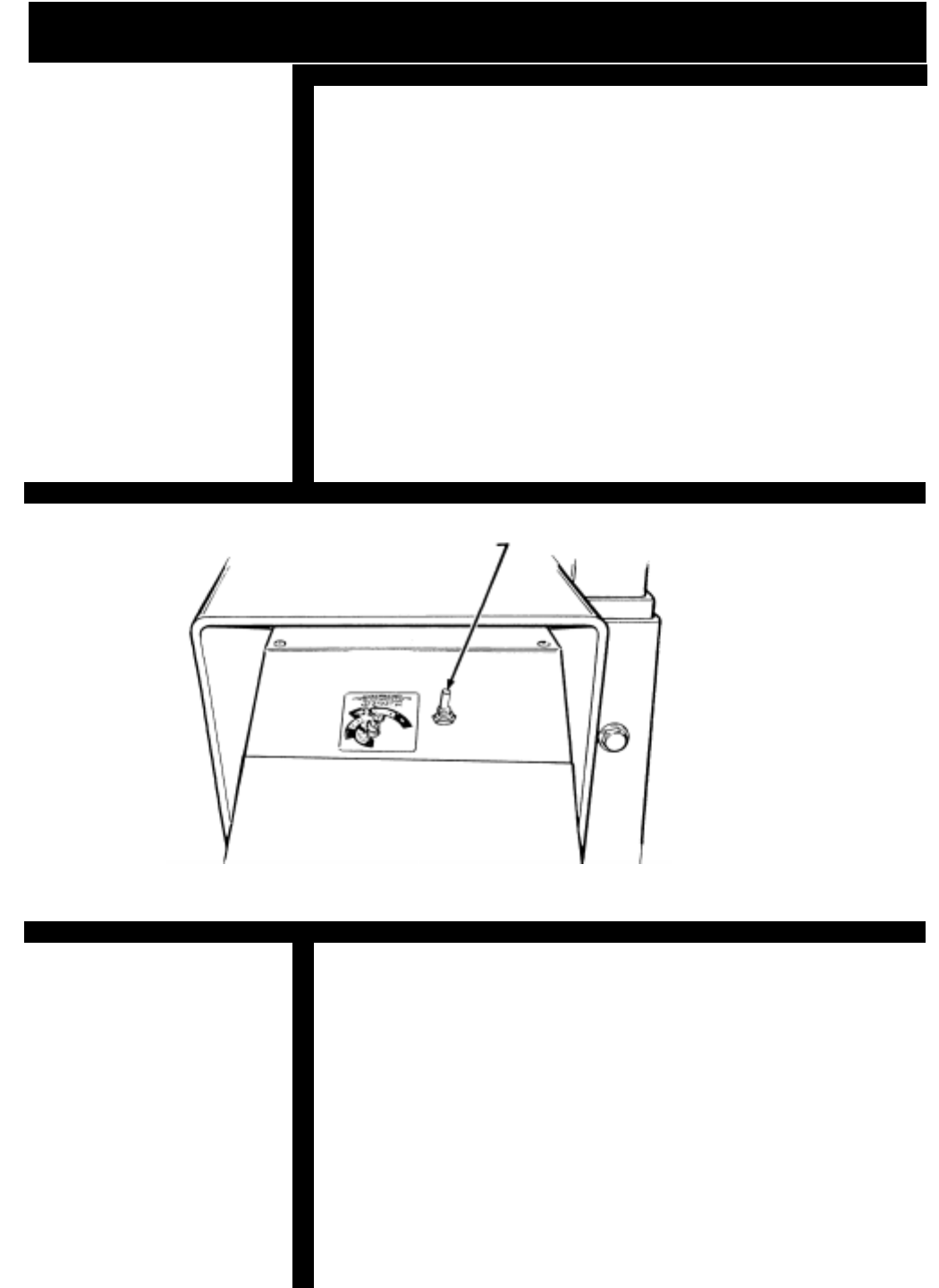
FUSE AND CIRCUIT BREAKER
FIGURE 23
ON/OFF SWITCH WITH CIRCUIT
BREAKER BUILT IN
CIRCUIT BREAKER
TO REPLACE A "BLOWN" FUSE:

© 1998 BRUNO INDEPENDENT LIVING AIDS, INC.
27
TO REPLACE A "BLOWN" FUSE (CONTINUED)
BATTERY CHARGER
BATTERY CHARGER FUSE REPLACEMENT:
FUSE REPLACEMENT
[ ] Use a fuse puller to remove the "old" fuse from PC Board
Spring Clips (be careful to avoid breaking the glass).
[ ] Replace the fuse using only a 5 ampere AGC or SFE
type fuse. (See figure 13 on page 15)
[ ] Turn the Power Switch to "ON".
[ ] Replace the Carriage Cover.
[ ] Reconnect the Battery Charger Leads.
[ ] Test the unit for proper operation.
WHEN THE INSTALLATION IS COMPLETE, TEST THE UNIT
FOR CORRECT OPERATION OF CALL/SEND, `ON/OFF'
SWITCH, FOOTREST, SAFETY SWITCHES, CARRIAGE LIMIT
SWITCHES AND SEAT SAFETY SWITCH.
TRAIN THE CUSTOMER TO USE THE STAIRWAY ELEVATOR
CORRECTLY AND SAFELY. BE SURE TO HAVE THEM OP-
ERATE THE UNIT WHILE YOU ARE THERE TO ANSWER ANY
QUESTIONS OR CONCERNS.
BATTERY CHARGER SEQUENCE IS AS FOLLOWS:
RED LED `ON' = AC Power on (power cord plugged in)
YELLOW CONTINUOUS LED = Batteries charging
FLASHING YELLOW LED = Batteries are 80% charged
GREEN CONTINUOUS LED = Batteries in “charge completing”
mode (or float / standby condition)
If the charger is subject to a power line surge, the AC input fuse
may `BLOW' This fuse is located beneath the power cord from the
wall outlet to prevent shock hazard, to replace fuse:
1) Remove Power Cord from wall outlet and charger socket.
2) Pull out on the fuse access panel.
3) Remove fuse.
4) Replace with the same size and type: (BUSS # GMC 4) 5 x
20mm-4AMP/125V-TIME LAG
*NOTE:
IF A THE GREEN
LIGHT IS FLASHING
ON THE CHARGER IT
IS DUE A PROBLEM
WITH THE BATTERY.
IF THE BATTERY
HAS NOT REACHED
THE END OF THE
FIRST STAGE OF
THE OPERATION
WITHIN 18 HOURS,
THE CHARGER MAY
DETERMINE THAT A
PROBLEM EXISTS
WITHIN THE BAT-
TERY OR THE BAT-
TERY IS TOO BIG
FOR THE
CHARGER'S OUTPUT
RATING.

© 1998 BRUNO INDEPENDENT LIVING AIDS, INC.
28
TURNING THE UNIT ON
VACATION / LONG TERM STORAGE
If the elevator will not be in use for and extended period of time the
unit should be moved 2"-3" away from the lower Charge contacts
and the red circuit breaker should be turned off. After the elevator
is in this position, the charger should be unplugged from the wall
outlet.
DO NOT unplug the charger from the wall outlet unless the circuit
breaker has been turned off. This will result in battery discharge or
premature battery failure.
[ ] To turn the unit back on , turn the circuit breaker on, plug the
charger back into the wall outlet.
NOTE: The batteries may need to be recharged before
normal use if the elevator was in the `off ' position for an
extended period of time. To do so , simply move the unit to
the LOWER charge contacts, and re-connect the charger to
the wall outlet (circuit breaker `on').

© 1998 BRUNO INDEPENDENT LIVING AIDS, INC.
29
NOTES
© 1998 BRUNO INDEPENDENT LIVING AIDS, INC.
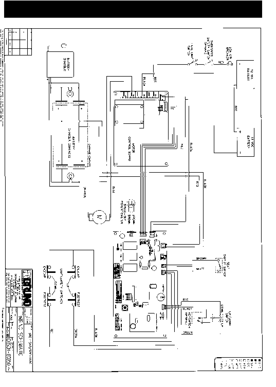
30 SCHEMATIC DIAGRAM
© 1998 BRUNO INDEPENDENT LIVING AIDS, INC.
31
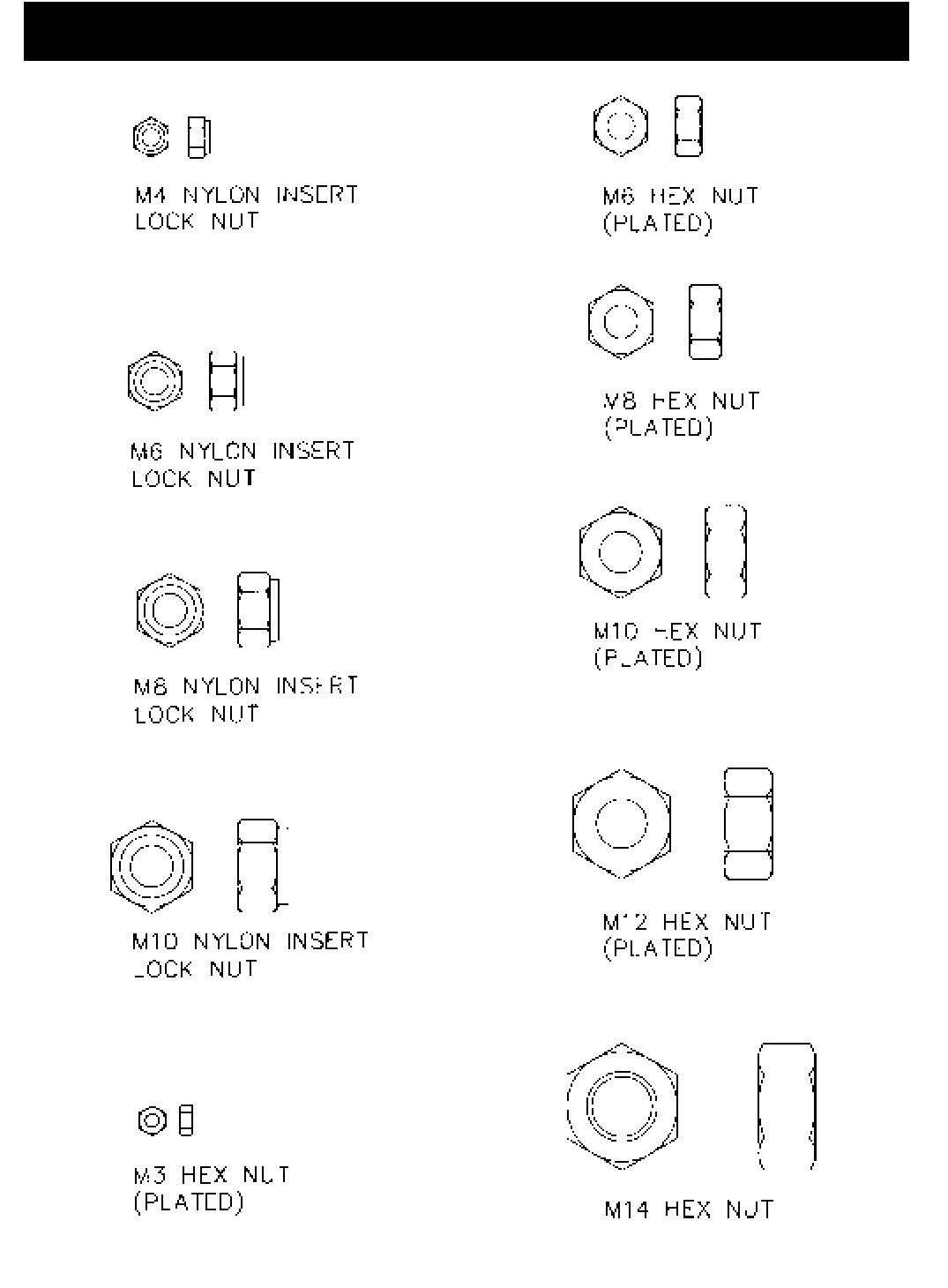
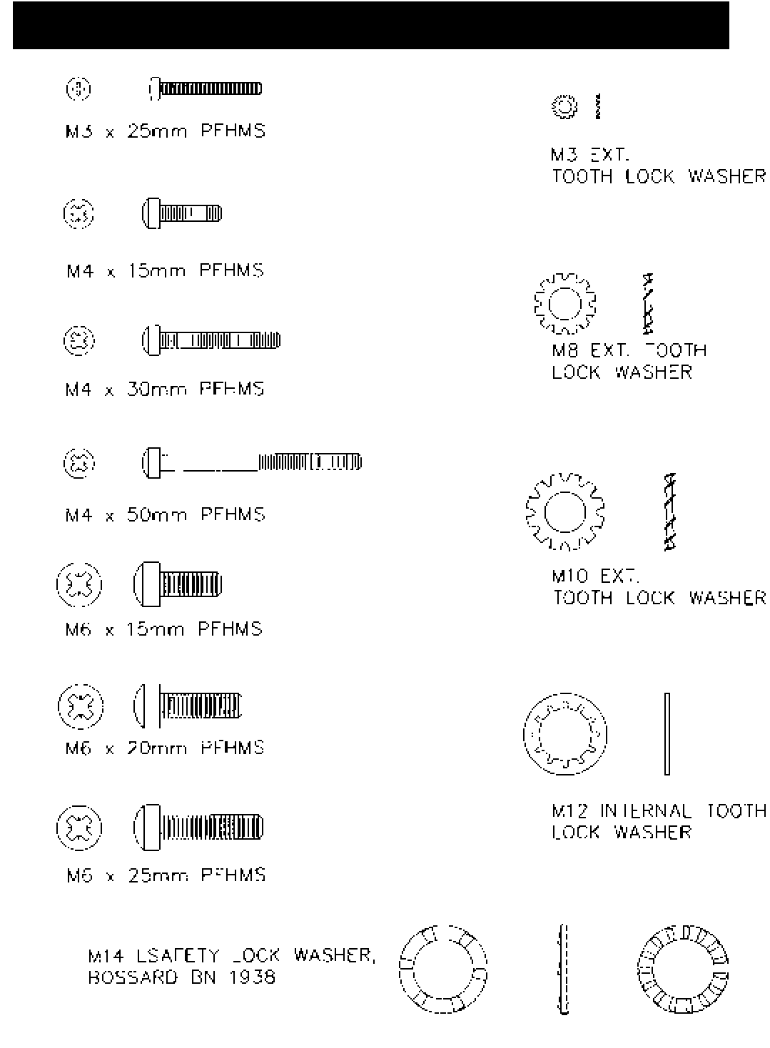
HARDWARE IDENTIFIER
© 1998 BRUNO INDEPENDENT LIVING AIDS, INC.
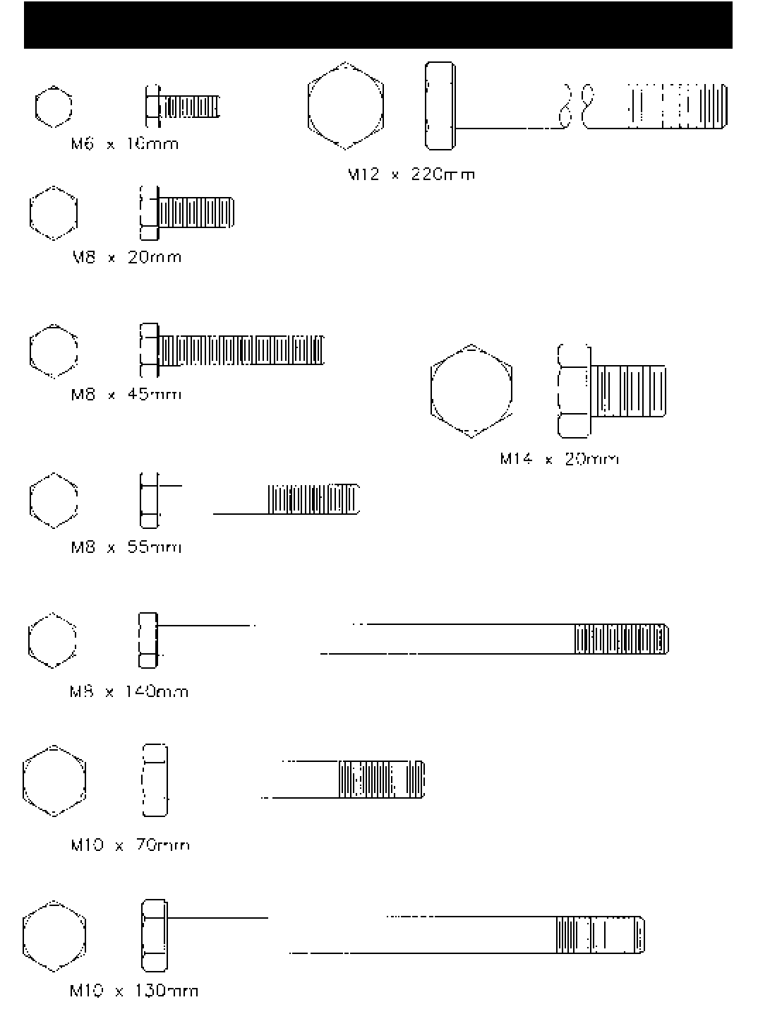
32 HARDWARE IDENTIFIER
© 1998 BRUNO INDEPENDENT LIVING AIDS, INC.
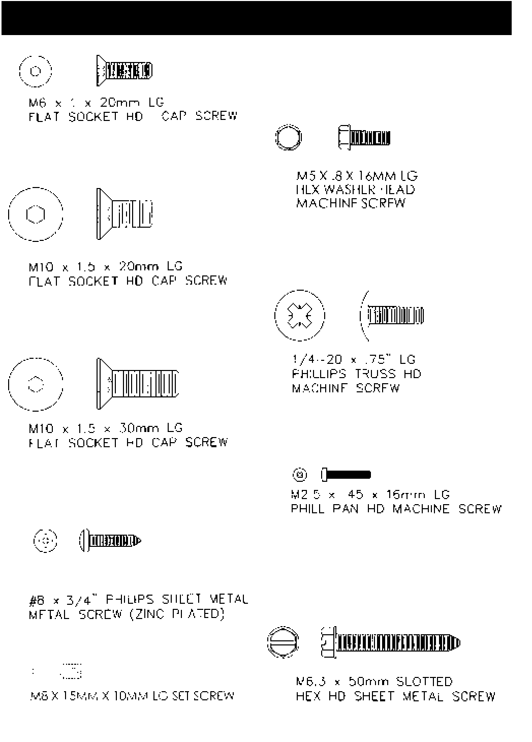
33
HARDWARE IDENTIFIER
© 1998 BRUNO INDEPENDENT LIVING AIDS, INC.
34 HARDWARE IDENTIFIER

© 1998 BRUNO INDEPENDENT LIVING AIDS, INC.
35
CHECK FUSE, REPLACE IF NECESSARY.
CHECK CIRCUIT BREAKER, RESET IF NECESSARY.
CHECK BATTERY CONNECTIONS.
CHECK FOOTREST SAFETY SWITCHES TO SEE IF ONE OF
THESE LIMIT SWITCHES IS DEPRESSED. SLIDING SAFETY
TRAY BELOW FOOTREST SHOULD SLIDE FREELY AND
SHOULD NOT STICK IN A POSITION WHICH WOULD DE-
PRESS ONE OF THE SAFETY SWITCHES.
CHECK FOR DISCHARGED BATTERIES. BATTERY VOLT-
AGE SHOULD BE IN A RANGE OF 16-28 VDC.
CHECK FOR DISCHARGED BATTERIES.
CHECK SETTING OF SPEED CONTROL POTENTIOMETER.
CHECK FOR LOOSE CONNECTIONS.
CHECK TO MAKE SURE CHARGER IS PLUGGED IN AND
WORKING.
UNIT IS NOT SET UP FOR CORRECT STAIR SIDE OPERA-
TION. MAKE CORRECT CONNECTIONS ACCORDING TO
INSTRUCTIONS IN THE INSTALLATION MANUAL.
NOTE: REFER TO PAGE 15 “REVERSING OPERATIONS”.
UNIT FAILS TO
OPERATE
UNIT OPERATES
SLOWLY, LACKS
POWER
CONTROLS OPERATE
BACKWARDS AND UNIT
GOES "UP" SLOWLY
AND "DOWN" FASTER
TROUBLESHOOTING

© 1998 BRUNO INDEPENDENT LIVING AIDS, INC.
36
UNIT OPERATES
ERRATICALLY OR
INTERMITTENTLY
WITH REMOTE
CALL/SEND
UNIT OPERATES
ERRATICALLY OR
INTERMITTENTLY
WITH A RIDER USING
THE ARMREST
MOUNTED CONTROL
SWITCH
RADIO INTERFERENCE CAN OCCUR IF MORE THAN ONE
RADIO CONTROL (OR OTHER RADIO DEVICE) IS OPERATING
ON THE SAME FREQUENCY, CAUSING THE SRE-1550 CALL /
SEND FUNCTION TO NOT WORK PROPERLY. FOR BEST
PERFORMANCE, MAINTAIN A DISTANCE FROM RADIO CON-
TROL DEVICES ON THE SAME FREQUENCY. RADIO INTER-
FERENCE CAN ALSO OCCUR NEAR HIGH VOLTAGE ELEC-
TRICAL WIRES, REINFORCED CONCRETE BUILDINGS OR CB
RADIOS. EXPERIMENT WITH REPOSITIONING THE ANTENNA
FOR THE CALL / SEND RECEIVER ON THE CARRIAGE.
Change delay setting on the receiver board to the 900 msec.
setting
Reorient or relocate receiving antenna.
Increase separation between antenna and the back of the
carriage.
Consult your dealer, an experienced technician or call our
Technical Service Department at 1-800-882-8768.
CHECK TO SEE THAT THE FOOTREST SAFETY TRAY IS NOT
DRAGGING ON THE STAIR NOSING OR HITTING DEBRIS ON
THE STAIRS, IF NECESSARY, REPOSITION THE STAIR RAIL
MOUNTING BRACKETS TO CORRECT THE PROBLEM.
CHECK THE RAIL FOR DEBRIS THAT MAY BUMP SAFETY
SWITCHES (FOOTREST AND CARRIAGE PANELS).
THIS IS CORRECT LIFT OPERATION, A SAFETY SWITCH IN
THE SEAT SWIVEL PREVENTS THE UNIT FROM OPERATING
WITH THE SEAT "OUT OF POSITION".
UNIT WILL NOT
OPERATE UNLESS THE
SEAT IS POSITIONED SO
THAT IT FACES THE
OPEN SIDE OF THE
STAIRS
TROUBLESHOOTING

© 1998 BRUNO INDEPENDENT LIVING AIDS, INC.
37
CHECK BATTERIES IN REMOTE CALL / SEND UNIT.
CHECK CONDITION AND POSITION OF THE CALL / SEND
ANTENNA ON THE CARRIAGE.
CHECK FOR LOOSE CONNECTION.
TRANSMITTERS MUST BE `LEARNED' TO RECEIVER.
CONNECTIONS WERE NOT MADE CORRECTLY WHEN
CHANGING UNIT FROM LEFT-SIDE TO RIGHT-SIDE OPERA-
TION. CONSULT INSTALLATION MANUAL FOR DIAGRAM OF
CORRECT WIRING CONFIGURATION.
CHECK LIMIT SWITCH IN CARRIAGE ASSEMBLY FOR
PROPER OPERATION.
TROUBLESHOOTING
UNIT DOES NOT SHUT
OFF WHEN IT HITS THE
BUMPER AT THE END
OF THE RAIL
UNIT WILL NOT
OPERATE WITH
CALL / SEND
REMOTE
© 1998 BRUNO INDEPENDENT LIVING AIDS, INC.
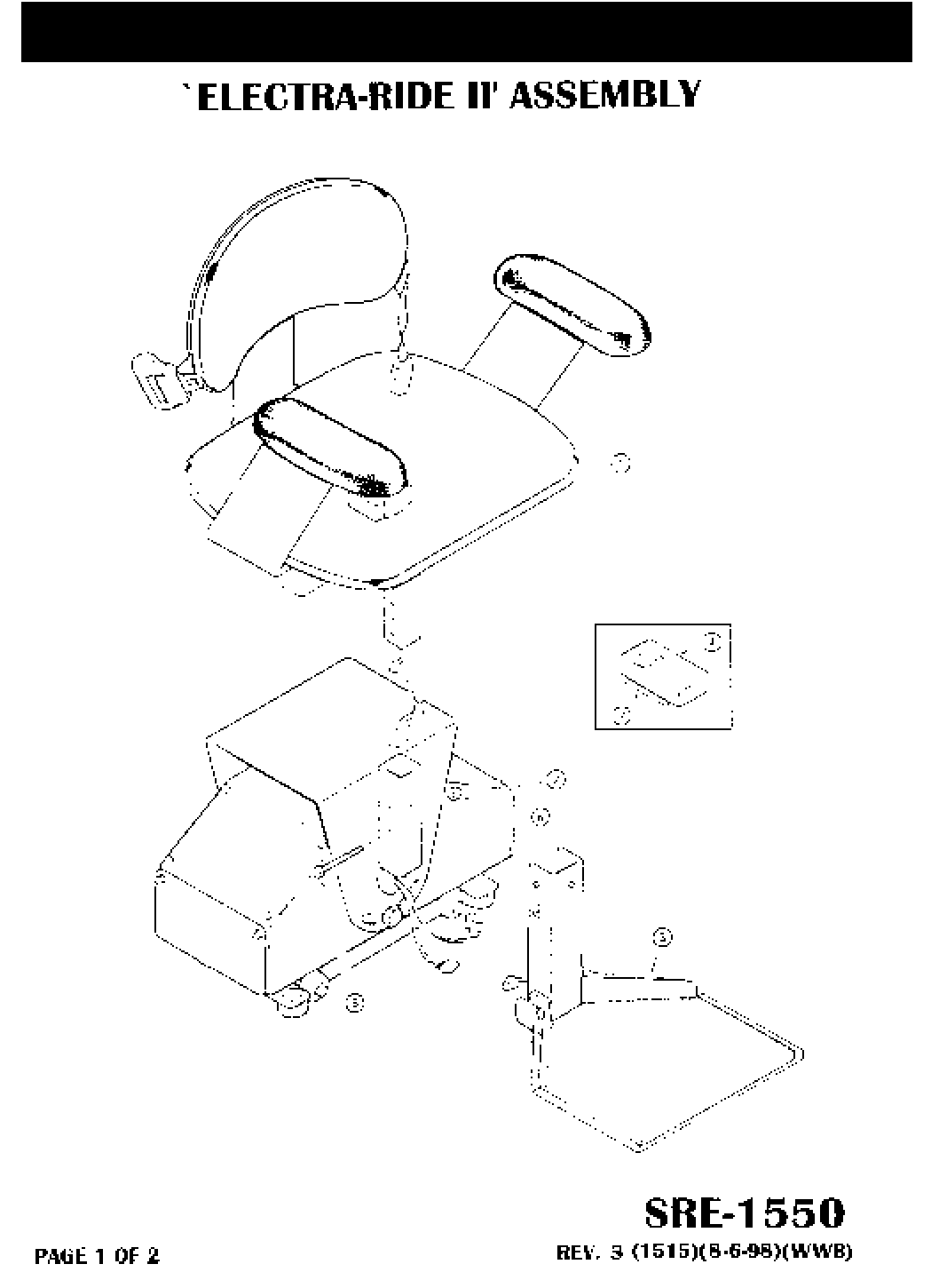
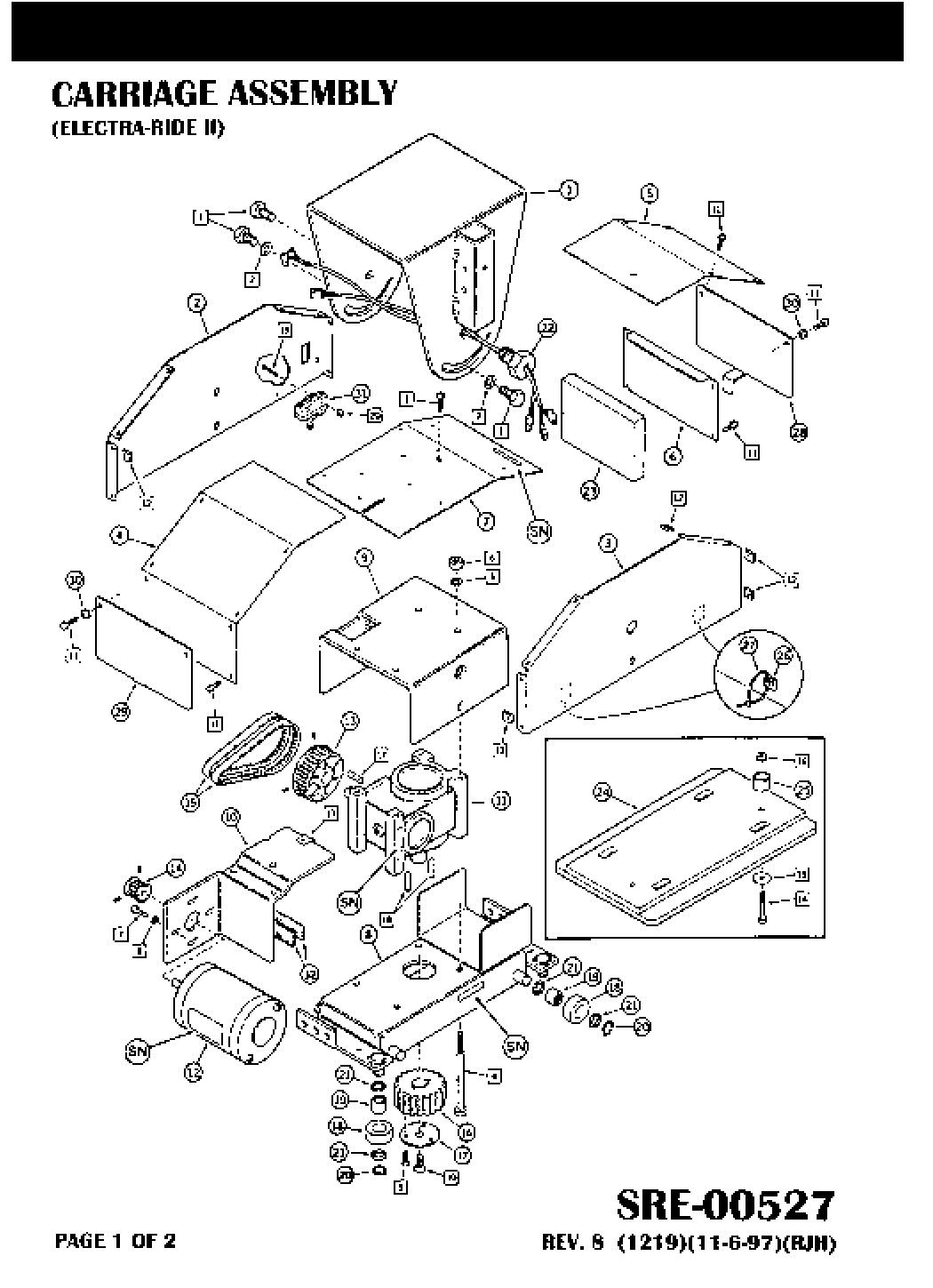
38 EXPLODED VIEW
© 1998 BRUNO INDEPENDENT LIVING AIDS, INC.
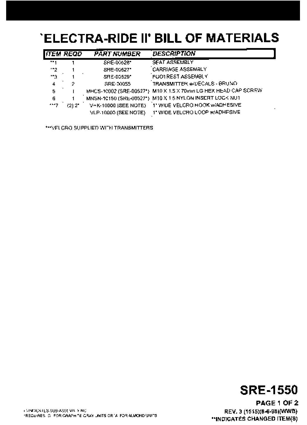
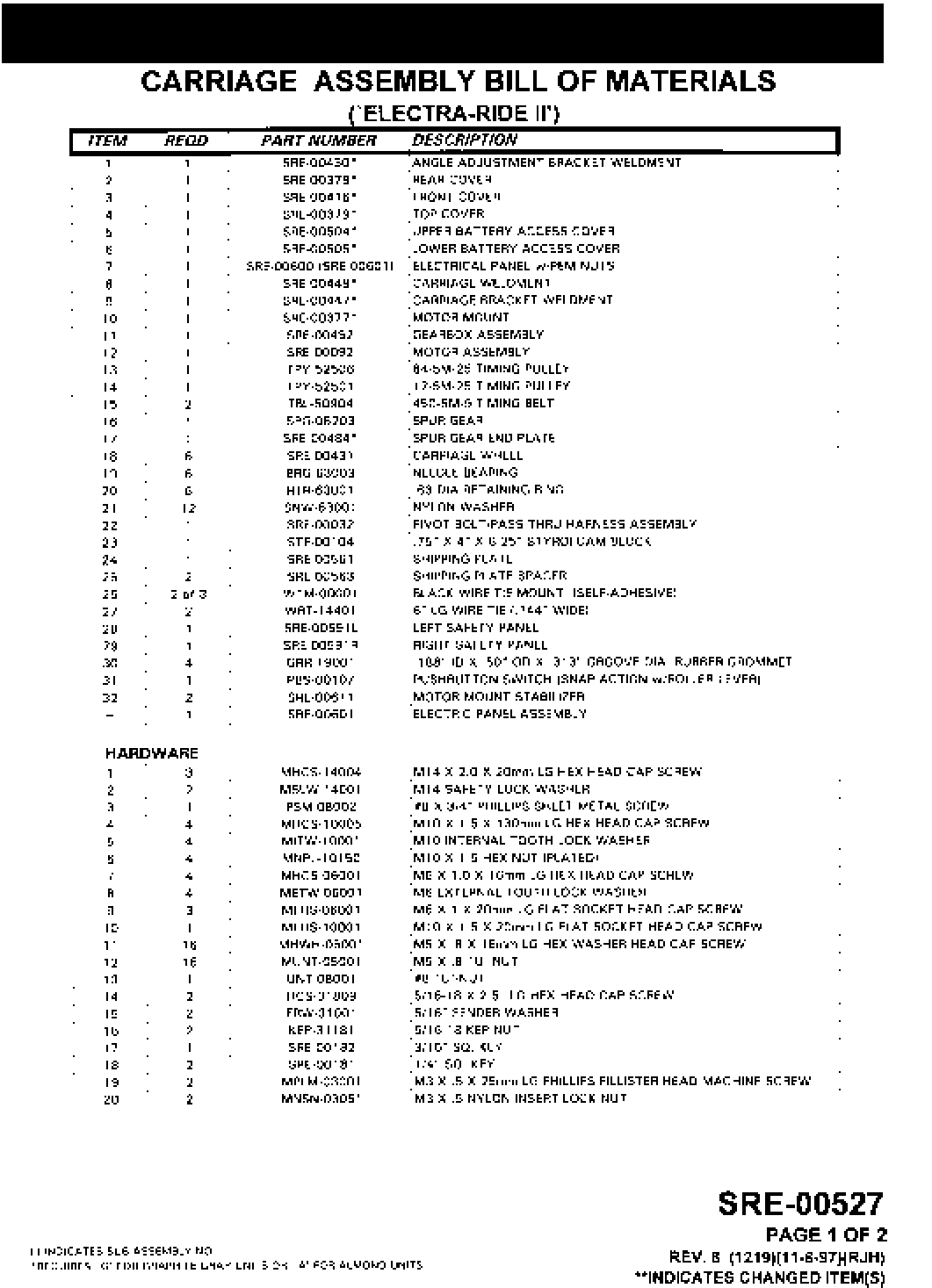
39
PARTS LISTING
© 1998 BRUNO INDEPENDENT LIVING AIDS, INC.
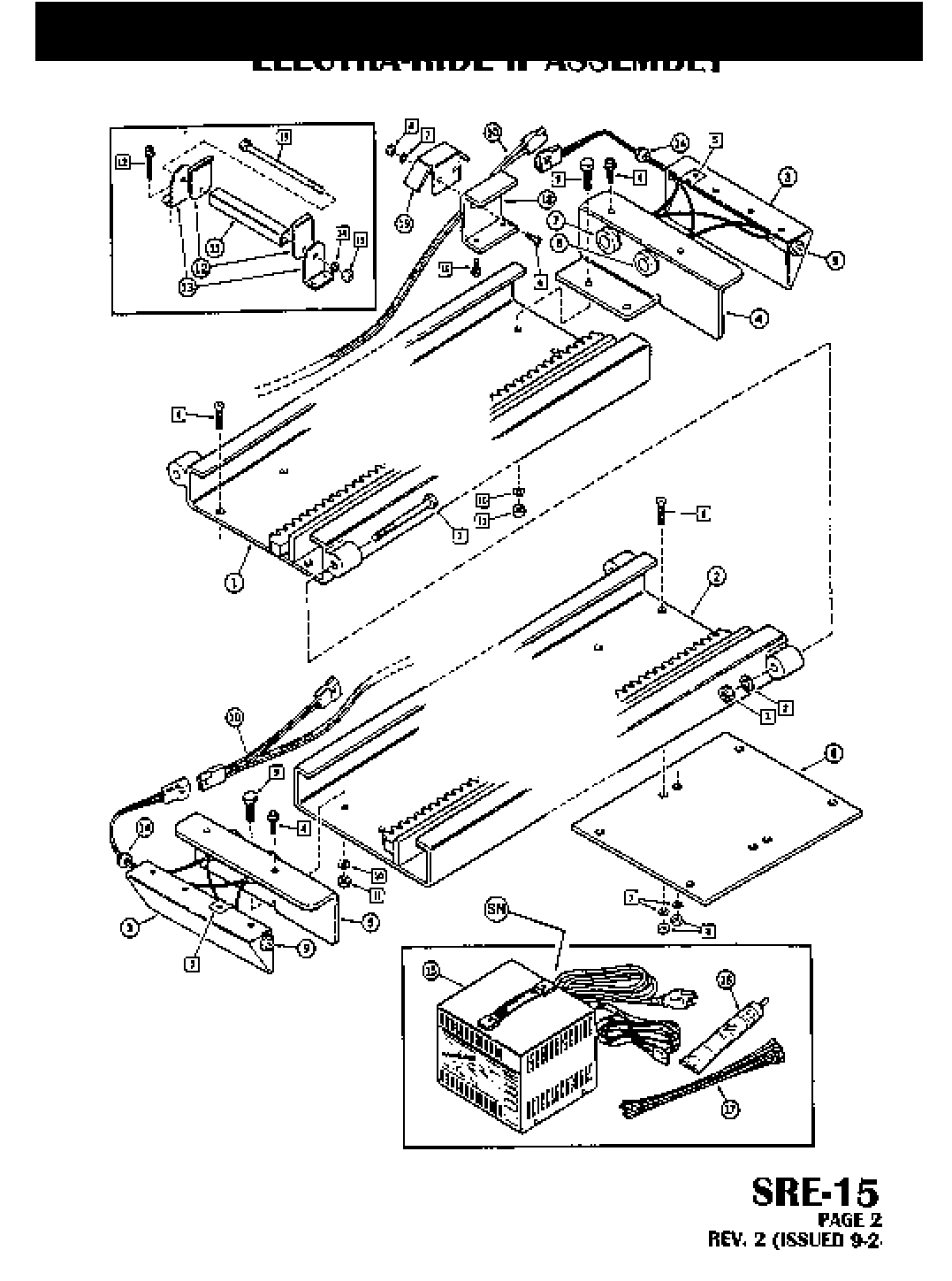
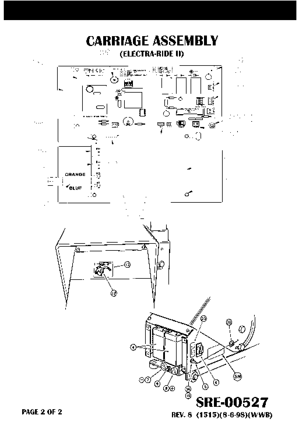
40 EXPLODED VIEW
© 1998 BRUNO INDEPENDENT LIVING AIDS, INC.
41
PARTS LISTING
© 1998 BRUNO INDEPENDENT LIVING AIDS, INC.
42 EXPLODED VIEW
© 1998 BRUNO INDEPENDENT LIVING AIDS, INC.
43
PARTS LISTING
© 1998 BRUNO INDEPENDENT LIVING AIDS, INC.
44 EXPLODED VIEW
© 1998 BRUNO INDEPENDENT LIVING AIDS, INC.
45
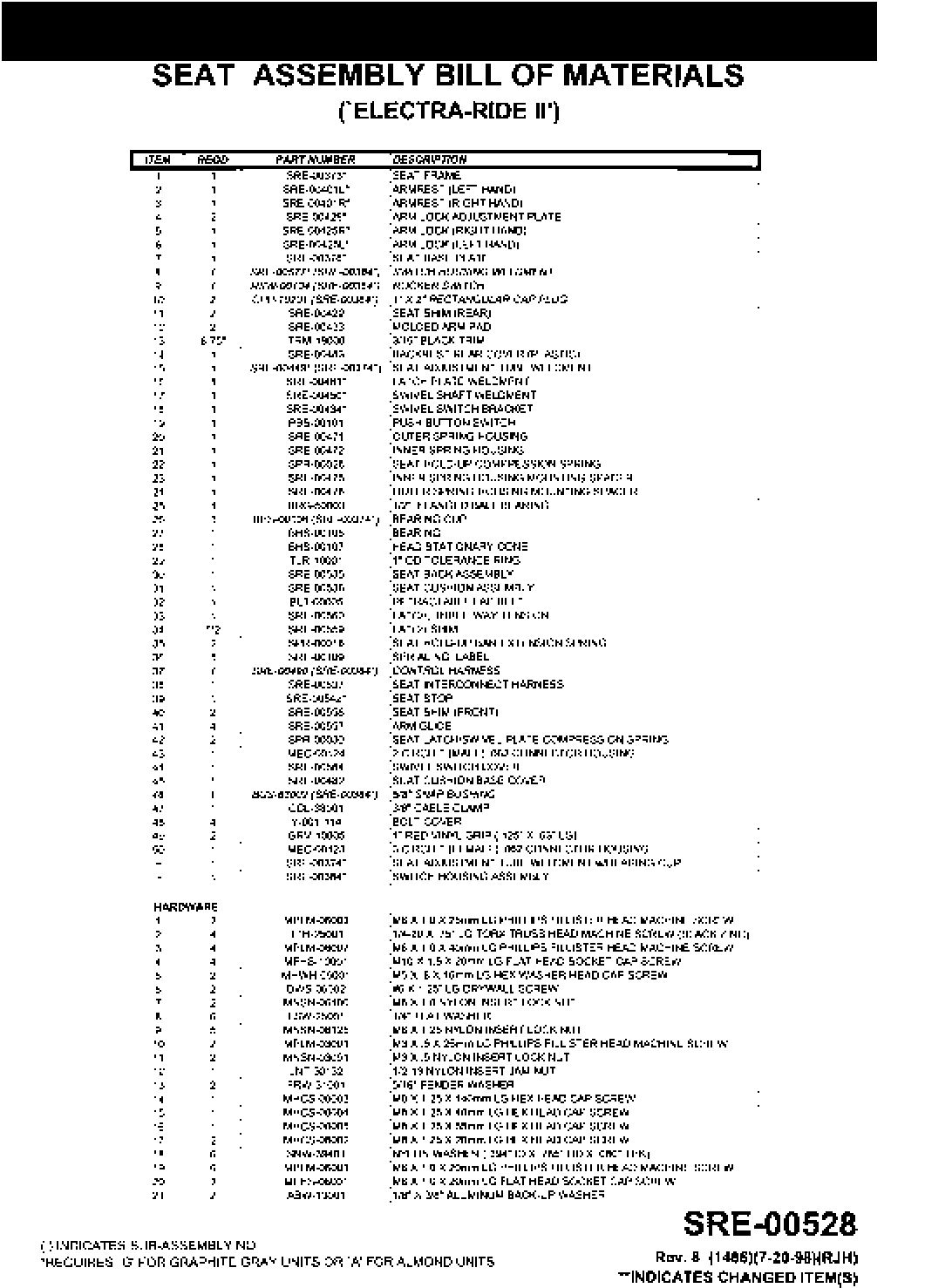
PARTS LISTING
© 1998 BRUNO INDEPENDENT LIVING AIDS, INC.
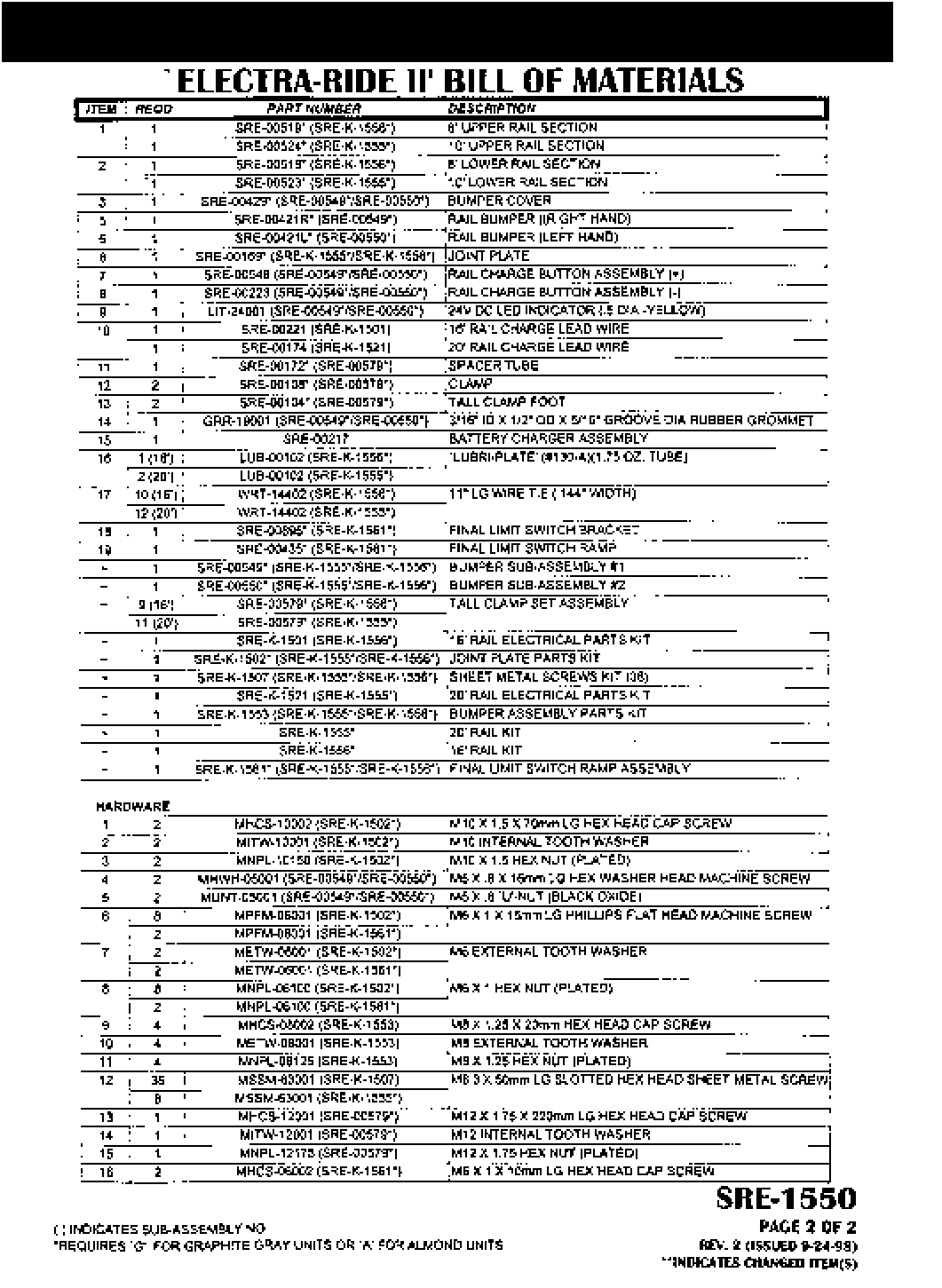
46 EXPLODED VIEW
© 1998 BRUNO INDEPENDENT LIVING AIDS, INC.
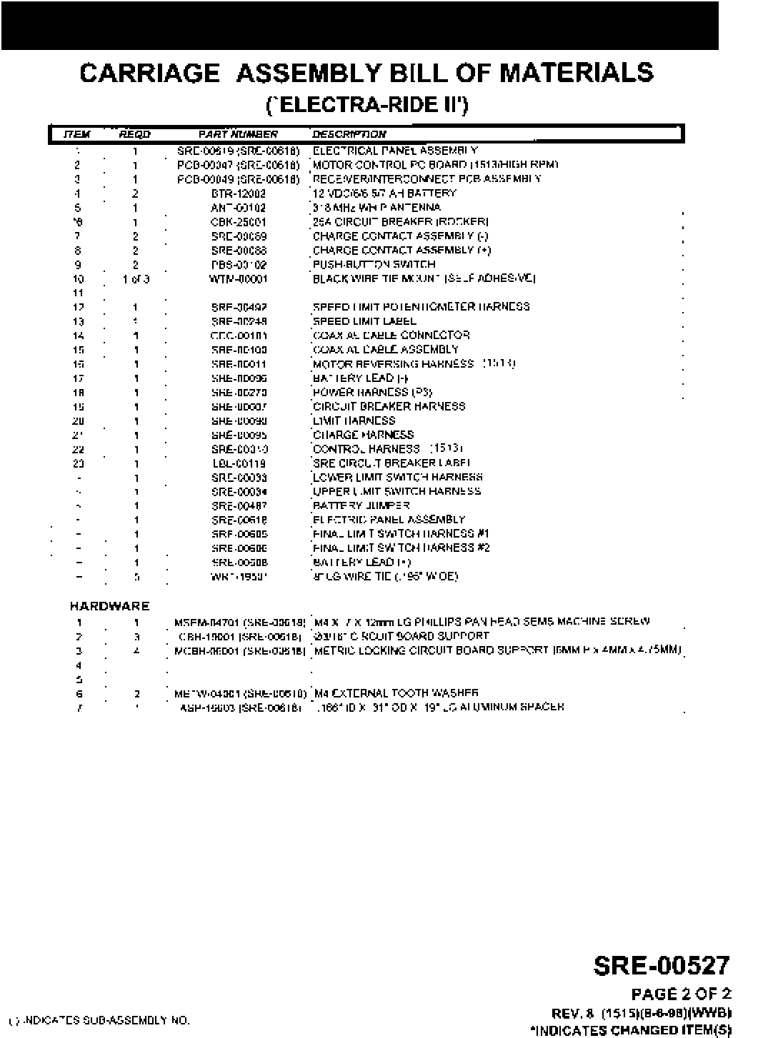
47
PARTS LISTING
© 1998 BRUNO INDEPENDENT LIVING AIDS, INC.
48 EXPLODED VIEW
© 1998 BRUNO INDEPENDENT LIVING AIDS, INC.
49
PARTS LISTING
© 1998 BRUNO INDEPENDENT LIVING AIDS, INC.
50
OVER SPEED ADJUSTMENT FOR COMMERCIAL UNITS
[ ] Before installing the carriage the overspeed cam must be
adjusted to line up with the overspeed housing.
[ ] Looking at the end of the carriage, line the white mark on the
cam with the white mark on the over speed housing.
[ ] Slide carriage on rail making sure not to move the aline-
ment.
[ ] If the overspeed should be tripped while servicing or
installing. The cam may be reset by rotating the cam back to its
detent position. By bypassing the overspeed switch and
running the drive unit up, the cam can be rotated in by hand.
[ ] Should a failure occur which would activate the overspeed,
the complete drive unit will have to be removed from the rail
and returned to the dealer or the manufacture to determine
the reason for the failure. Repairs would then have to be
completed before unit could be used again.
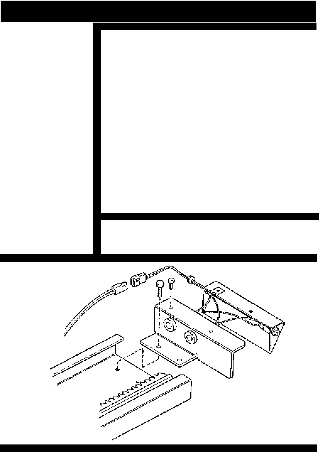
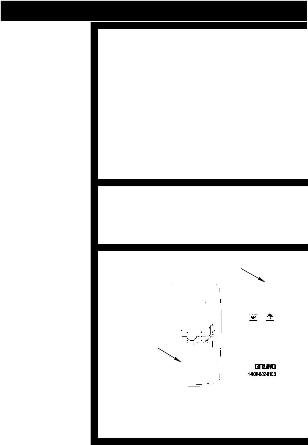
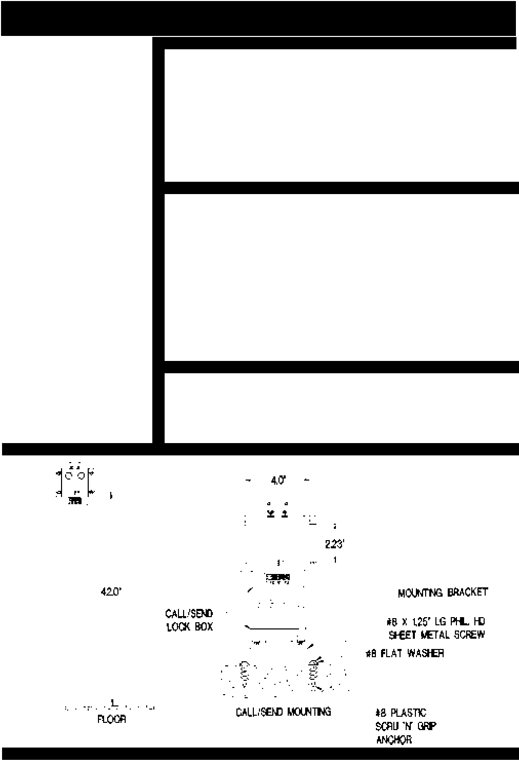
[ ] Install call/send lock boxes as shown below. The key
switch should be approximately 42" from floor. One box
should be installed at the top of the stairs and one at the
bottom.
RESETTING OVERSPEED
FIGURE 24
MOUNTING CALL/SEND LOCK BOX
NOTE:
INSTALLATION OF
CALL/SEND MAY VARY
BY LOCAL CODE.
PLEASE REFER TO
LOCAL CODES FOR
INSTALLATION GUIDE-
LINES.
THE SEAT KEY SWITCH
AND ROCKER SWITCH
ARE LOCATED UNDER
THE RIGHT ARM PAD.
(ON YOUR RIGHT AS
YOU ARE SITTING IN
THE SEAT.) SHOULD
THE INSTALLATION
REQUIRE A LEFT HAND
INSTALLATION FOL-
LOW THE INSTRUC-
TIONS FOR REVERSING
OPERATIONS ON PAGE
15.
ADJUST OVERSPEED FOR COMMERCIAL UNITS ONLY

© 1998 BRUNO INDEPENDENT LIVING AIDS, INC.
51
LIMITED WARRANTIES ON THE "ELECTRA-RIDE II"
Bruno Independent Living Aids, Inc., warrants to the original purchaser the "ELECTRA-RIDE II
STAIRWAY ELEVATOR" manufactured by us to be free from defects in material and workmanship under
normal use and service for a period of one year. Our obligation under this warranty shall be limited to the
repair or exchange of any part or parts which may thus prove defective under normal use and which our
examination shall disclose to our satisfaction to be defective.
THIS WARRANTY IS EXPRESSLY IN LIEU OF ALL OTHER WARRANTIES EXPRESSED OR IMPLIED
INCLUDING THE WARRANTIES OF MERCHANTABILITY AND FITNESS FOR USE AND OF ALL OTHER
OBLIGATIONS OR LIABILITIES ON OUR PART, AND WE NEITHER ASSUME, NOR AUTHORIZE ANY
OTHER PERSON TO ASSUME FOR US, ANY OTHER LIABILITY IN CONNECTION WITH THE SALE OF
THE PRODUCT, INCLUDING, BUT NOT LIMITED TO, INCIDENTAL AND CONSEQUENTIAL DAMAGES.
THIS WARRANTY SHALL NOT APPLY TO ANY PART OF THE PRODUCT WHICH HAS BEEN SUBJECT TO
ACCIDENT, NEGLIGENCE, ALTERATION, ABUSE OR MISUSE. WE MAKE NO WARRANTY WHATSO-
EVER IN RESPECT TO ACCESSORIES OR PARTS NOT SUPPLIED BY US. NO WARRANTY IS MADE
EXCEPT TO THE ORIGINAL PURCHASER. THE TERM "ORIGINAL PURCHASER," AS USED IN THIS
WARRANTY, SHALL BE DEEMED TO MEAN RETAIL CUSTOMERS TO WHOM THE PRODUCT IS ORIGI-
NALLY SOLD OR RENTED. THIS WARRANTY SPECIFICALLY EXCLUDES LABOR AND SERVICE CALLS
AND DEFECTS CAUSED BY UNAUTHORIZED WORK PERFORMED ON THE ELEVATOR.
For repair or replacement under this limited warranty, the product must be returned, freight prepaid, to
Bruno Independent Living Aids, Inc., 1780 Executive Drive, Oconomowoc, Wisconsin, 53066. Attention:
Service Department. After warranty service, the product will be returned freight collect. No warranty will be
honored unless the customer can show proof of purchase (with date of purchase) and unless notice is
given to Bruno Independent Living Aids, Inc., within 10 working days of the date of purchase. Some states
do not allow the exclusion or limitation of incidental or consequential damages, so the above limitation or
exclusion may not apply to you. This warranty gives you specific legal rights, and you may also have other
rights which vary from state to state.
TM
TM

TABLE OF CONTENTS
INTRODUCTION.................................................................................................... 1
PACKING LIST ...................................................................................................... 2
PREFACE ..........................................................................................................3 - 4
INSTALLATION .................................................................................................5 -16
TOOLS NECESSARY FOR INSTALLATION................... 5
BUMPER BRACKET INSTALLATION.............................. 6
FITTING THE RAIL............................................................... 6
CUTTING THE RAIL............................................................ 7
RAIL JOINT ASSEMBLY.....................................................7
POSITION RAIL CLAMP ASSEMBLIES.....................8 - 9
CALL/SEND ANTENNA INSTALLATION......................... 9
MOUNT THE CARRIAGE ON THE UPPER RAIL........... 10
ADJUST THE CARRIAGE ANGLE................................... 10
INSTALL SEAT ASSEMBLY..............................................11
SEAT HEIGHT ADJUSTMENT.......................................... 11
INSTALL FOOTREST ASSEMBLY................................... 12
ELEVATOR TRIAL RUN..................................................... 12
TESTING FOOTREST SAFETY SWITCH........................ 13
SAFETY SWITCH PANEL..................................................13
INSTALLATION OF FINAL LIMIT ACTUATION................ 14
INSTALLATION ON RIGHT SIDE OF STAIRWAY........... 15
CHANGING CONTROLS FROM RIGHT TO LEFT ARMREST
.15
CIRCUIT BOARD OPERATION..................................16 - 17
INSTALL FOOT CLAMPS.................................................. 18
INSTALL THE UPPER BUMPER BRACKET.................. 18
LUBRICATION......................................................................19
CHARGER/RAIL LEAD APPLICATION.....................19 - 21
REMOTE CALL/SEND.......................................................................................... 22
SPEED ADJUSTMENT........................................................................................ 23
SEAT LATCH AND ARM LOCK .........................................................................24
SEAT ADJUSTMENT............................................................................................ 25
FUSE AND CIRCUIT BREAKER........................................................................ 26
FUSE REPLACEMENT........................................................................................ 27
LONG TERM STORAGE.......................................................................................28
NOTES..................................................................................................................... 29
SCHEMATIC DIAGRAM....................................................................................... 30
HARDWARE IDENTIFIER ............................................................................31 - 34
TROUBLESHOOTING ..................................................................................35 - 37
EXPLODED VIEWS ...........................................................38 ,40, 42, 44, 46 & 48
PARTS LISTINGS ..............................................................39, 41, 43, 45, 47 & 49
APPLICATIONS FOR COMMERCIAL UNITS ................................................. 50
LIMITED WARRANTY........................................................................................... 51

REGULATORY INFORMATION
FCC REGULATIONS
This equipment has been tested and found to comply with the limits for a Class B digital device,
pursuant to Part 15 of the FCC rules. These limits are designed to provide reasonable protection
against harmful interference in a residential installation. This equipment generates, uses, and can
radiate radio frequency energy, and if not installed and used in accordance with the instructions,
may cause harmful interference to radio communications. However, there is no guarantee that
interference will not occur in a particular installation. If this equipment does cause harmful interfer-
ence to radio or television reception, which can be determined by turning the equipment off and
on, the user is encouraged to try to correct the interference by one or more of the of the following
measures:
Reorient or relocate receiving antenna.
Increase separation between equipment and receiver.
Consult your dealer or an experienced radio/TV technician.
INSTALLATION MANUAL
MAN-1550-1
REVISED 08-10-98
1780 EXECUTIVE DR.,P.O., BOX 84
OCONOMOWOC, WI 53066
(414) 567-4990
FAX: (414) 567-4341
TECHNICAL SERVICE NUMBER: 1-800-882-8768
SALES & CUSTOMER SERVICE NUMBER: 1-800-882-8183
ARE BOTH GOOD THROUGHOUT THE U.S.
AND CANADA
TM
SRE-1550 ELECTRA-RIDE II STAIRWAY ELEVATOR