Bryant 593C Users Manual
593C to the manual 6d9a511a-734a-425e-81ba-d20daa4c21a3
2015-02-02
: Bryant Bryant-593C-Users-Manual-411778 bryant-593c-users-manual-411778 bryant pdf
Open the PDF directly: View PDF ![]() .
.
Page Count: 28
Form No. PDS 593C.18.7
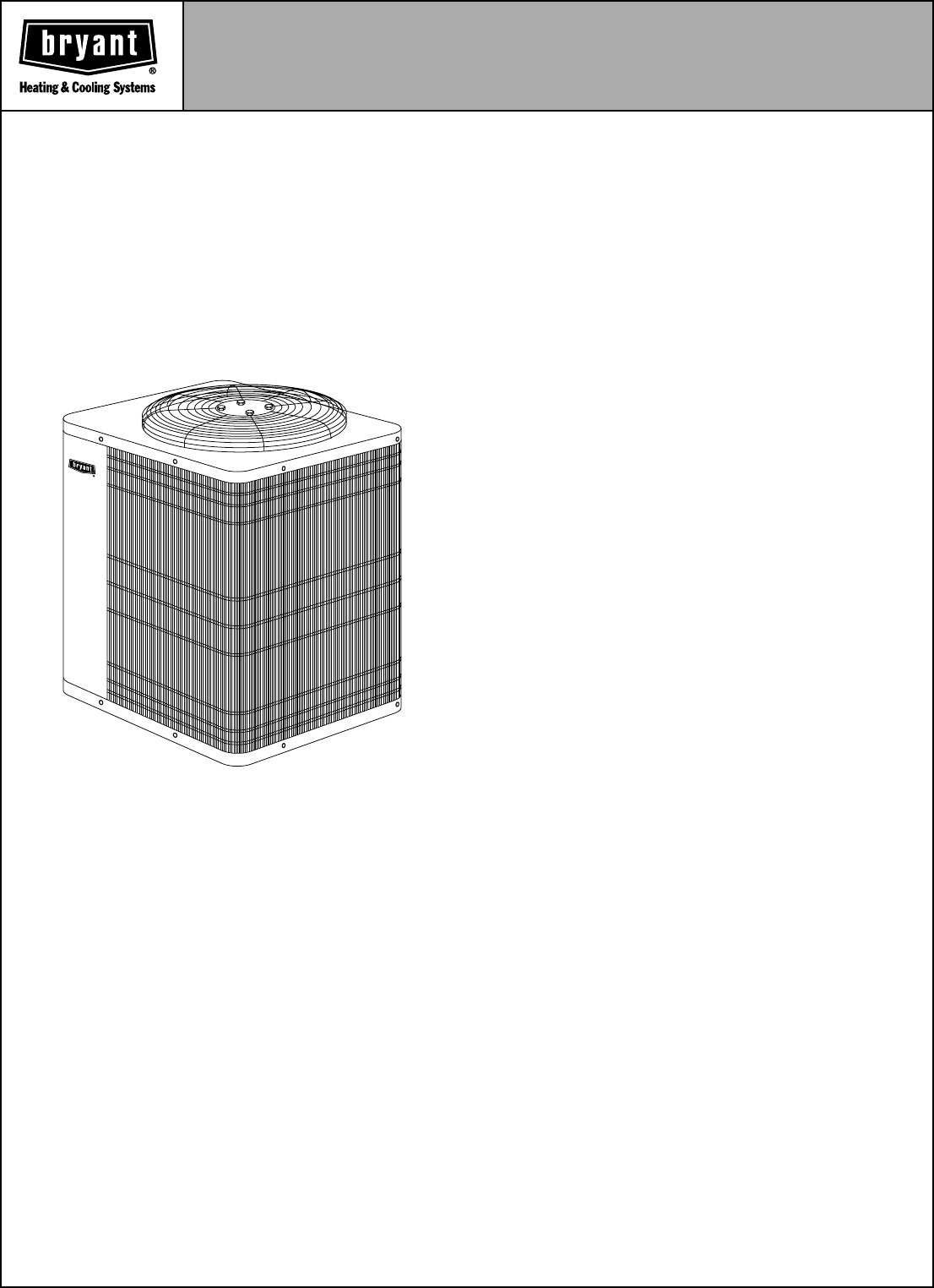
ELECTRIC
AIR CONDITIONER
Model 593C (60 Hz)
Sizes 018 thru 060
WEATHER-PROTECTIVE CABINET
—Steel is galvanized and
coated with a layer of zinc phosphate. A coat of modified poly-
ester powder coating is then applied and baked-on, providing
each unit with a hard, smooth finish that will last for many years.
All screws on cabinet exterior are ceramic coated for a long-
lasting, rust-resistant, quality appearance.
HEAVY DUTY INLET GRILLE
—The DuraGuard™ coil protec-
tor, made of a coated steel wire grid with vertical 3/8 in. spacing,
is designed to help protect the coil from inclement weather, van-
dalism, and incidental damage. It provides protection while not
restricting airflow and maintaining ease of coil inspection and
cleaning.
TOTALLY ENCLOSED FAN MOTOR
—Means greater reliability
under adverse weather conditions and dependable perfor-
mance for many years. The permanent-split-capacitor type
motor was designed for optimum efficiency. Then the motor was
tested and qualified under extreme conditions to help ensure
the greatest reliability.
UNIT DESIGN
—Copper tube, enhanced aluminum fin coil is
designed for optimum heat transfer. Vertical air discharge car-
ries sound and hot condenser air up and away from adjacent
patio areas and foliage. Heat pump-style drain pan for easy
removal of water, dirt, and leaves.
BRYANT’S AEROQUIET SYSTEM
—Extremely low operating
sound is the result of special attention to the air moving through
the outdoor unit, and a specially designed sound enclosure sur-
rounding the compressor to eliminate sound transmission to the
rest of the systems.
APPLICATION VERSATILITY
—The 593C can be combined
with a wide variety of evaporator coils and blower packages to
provide quiet, dependable comfort. Unit can be installed on a
roof or at ground level on a slab.
EXTERNAL SERVICE VALVES
—Both service valves are
brass, front seating type with sweat connections. Valves are
externally located so refrigerant tube connections can be made
quickly and easily. Each valve has a service port for ease of
checking operating refrigerant pressures.
EASY SERVICEABILITY
—One access panel provides access
to electrical controls and compressor. Removal of wire dome
gives access to fan motor and removal of the top gives access
to the coil. For improved serviceability, all models are equipped
with a compressor terminal plug.
COMPRESSOR PROTECTION
—Each model is protected with
internal temperature- and current-sensitive overloads. An inter-
nal pressure relief valve provides high-pressure protection to
the refrigerant system.
LIMITED WARRANTY
—Standard 5-year warranty on all parts,
with an additional 10-year warranty on compressor.
Model 593C Energy-Efficient Air Conditioners incor-
porate innovative technology to provide quiet, reliable
cooling performance. Built into these units are the fea-
tures most desired by homeowners today. Standard
SEER ratings of 10.0 can reach as high as 11.2 when
combined with specific Bryant equipment. All models
are listed with ARI, UL (U.S. and Canada), and CEC.
AVAILABLE OPTIONS
ELECTRICAL RANGE
—All units are offered in 208–
230v single phase.
WIDE RANGE OF SIZES
—Available in 7 nominal
sizes from 018 through 060 to meet the needs of resi-
dential and light commercial applications.
—2—
AIR DISCHARGE
AIR DISCHARGE
AIR IN
AIR IN
AIR IN
3/8" DIA. TIEDOWN KNOCKOUTS
(2) PLACES
L
K
J
E
D
C
L
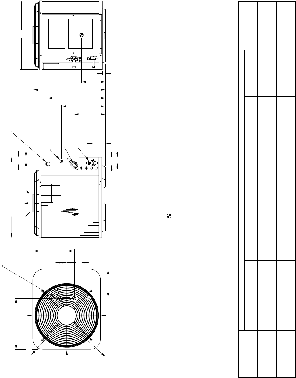
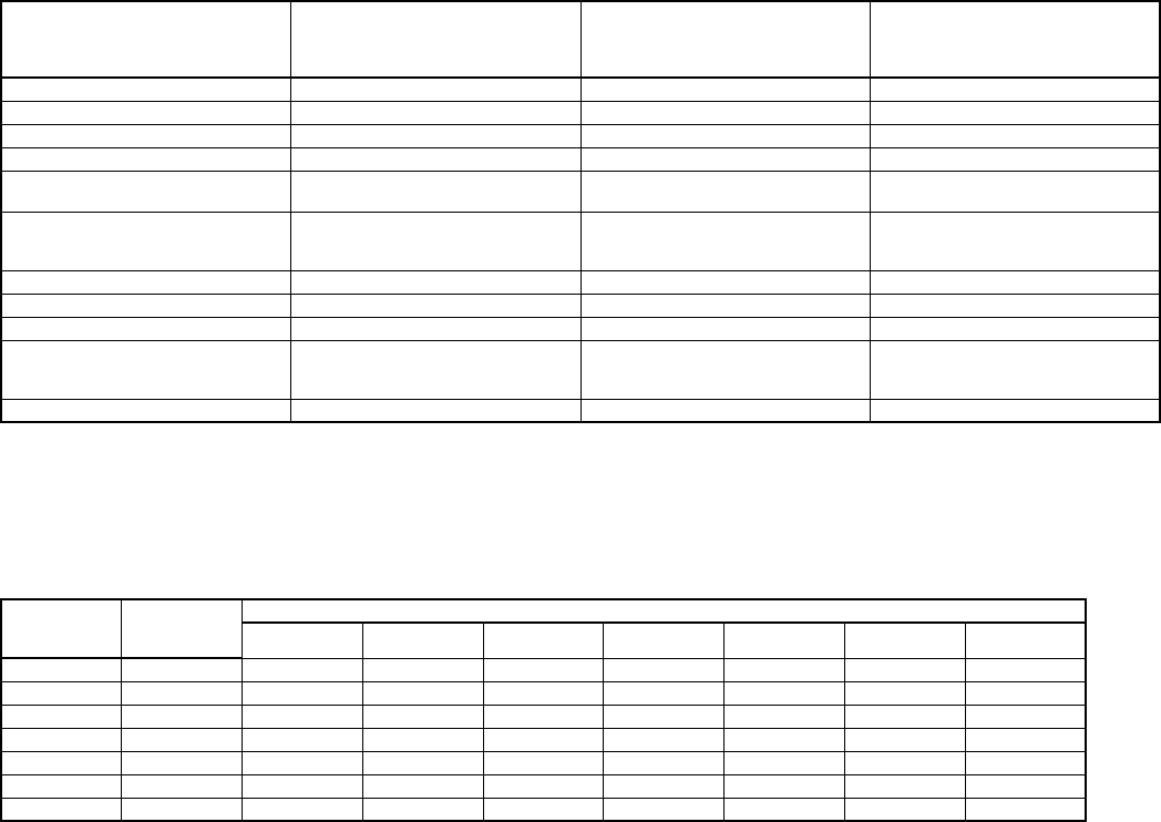
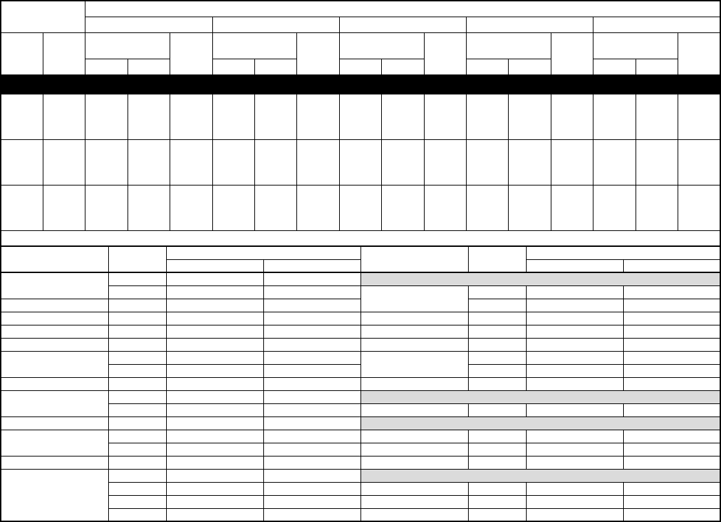
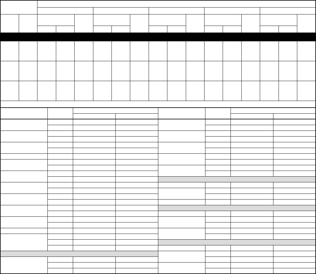
NOTES:
1. ALLOW 30" CLEARANCE TO SERVICE SIDE OF UNIT, 48" ABOVE UNIT, 6" ON ONE
SIDE, 12" ON REMAINING SIDE, AND 24" BETWEEN UNITS FOR PROPER AIRFLOW.
2. MINIMUM OUTDOOR OPERATING AMBIENT IN COOLING MODE IS 55°F,
(UNLESS LOW AMBIENT CONTROL IS USED) MAX. 125°F.
3. SERIES DESIGNATION IS THE 14TH POSITION OF THE UNIT MODEL NUMBER.
4. CENTER OF GRAVITY .
ACCESS
PANEL
1 1/4"
2 1/2"
AIR DISCHARGE
1 3/4"
4 3/16"
3/8" DIA. LIQUID
LINE CONN.
H DIA. VAPOR
LINE CONN.
7/8" DIA. HOLE
FIELD POWER SUPPLY CONN. 7/8" DIA.
HOLE WITH 1 1/8" DIA. KNOCKOUT
AND 1 3/8" DIA. KNOCKOUT
10 1/2"
FIELD CONTROL
SUPPLY CONN
1 9/16"
C
F
N
G
A
B
M
DIMENSIONS (IN.)
UNIT
SIZE SERIES
UNIT DIMENSIONS MINIMUM MOUNTING
PAD DIMENSIONSABCDEFGHKLMN
018 C, D 23-13/16 22-1/2 26-3/16 4-1/8 7-1/8 13-13/16 18-3/8 5/8 12-1/2 15-1/2 10-1/2 2-3/8 22 x 26
024 C, D 23-13/16 22-1/2 26-3/16 4-1/8 7-1/8 13-13/16 18-3/8 5/8 12-1/2 15-1/2 10-1/2 2-3/8 22 x 26
030 C, D 27-13/16 22-1/2 26-3/16 4-1/8 7-1/8 15-15/16 22-3/8 3/4 12-1/2 15-1/2 11-1/2 2-3/8 22 x 26
036 C, D 33-13/16 22-1/2 26-3/16 4-1/8 7-1/8 21-15/16 28-3/8 3/4 12-1/2 15-1/2 13 2-3/8 22 x 26
042 C, D 27-13/16 30 33 5-1/16 9-11/16 15-15/16 22-3/8 7/8 16-1/2 20-3/8 12-5/16 2-15/16 28 x 31
048 C 33-13/16 30 33 5-1/16 9-11/16 21-15/16 22-3/8 7/8 15-1/2 18 13-1/2 2-15/16 28 x 31
060 C 39-13/16 30 33 5-1/16 9-11/16 27-15/16 34-3/8 7/8 15-1/2 18 16-1/2 2-15/16 28 x 31
A99067
—3—
RECOMMENDED TUBE DIAMETERS
* For tube sets between 50 and 175 ft, consult Residential Split System Long-Line Application Guideline.
CHECK-FLO-RATER® PISTON
* Piston listed is for any approved non-capillary tube coil combination. Piston is
shipped with outdoor unit and must be installed in an approved indoor coil.
UNIT
SIZE
LIQUID TUBE DIAMETER (IN.) VAPOR TUBE DIAMETER (IN.)
0 to 50 Ft
Tube Length Long-Line Applications*
0 to 50 Ft
Tube Length
Long-Line Applications*
(Maximum Diameter)
018, 024
3/8 3/8
5/8 3/4
030, 036 3/4 7/8
042, 048 7/8 1-1/8
060 1-1/8 1-1/8
UNIT SIZE—SERIES
PISTON*
IDENTIFICATION NO.
018-C, D 55
024-C, D 57
030-C, D 67
036-C, D 73
042-C, D 78
048-C 82
060-C 96
CERTIFICATION APPLIES ONLY
WHEN THE COMPLETE SYSTEM
IS LISTED WITH ARI.
M
A
N
U
F
A
C
T
U
R
E
R
C
E
R
T
I
F
I
E
D
T
O
A
R
I
A
S
C
O
M
P
L
Y
I
N
G
W
I
T
H
A
R
I
S
T
A
N
D
A
R
D
2
1
0
U
N
I
T
A
R
Y
A
I
R
C
O
N
D
I
T
I
O
N
I
N
G
E
Q
U
I
P
M
E
N
T
REGISTERED QUALITY SYSTEM
—4—
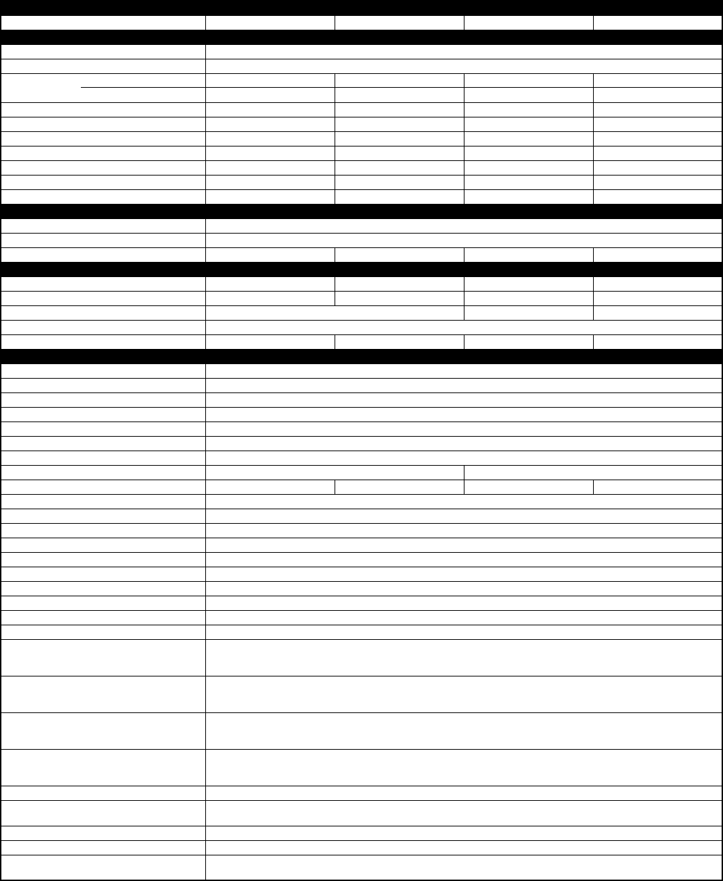
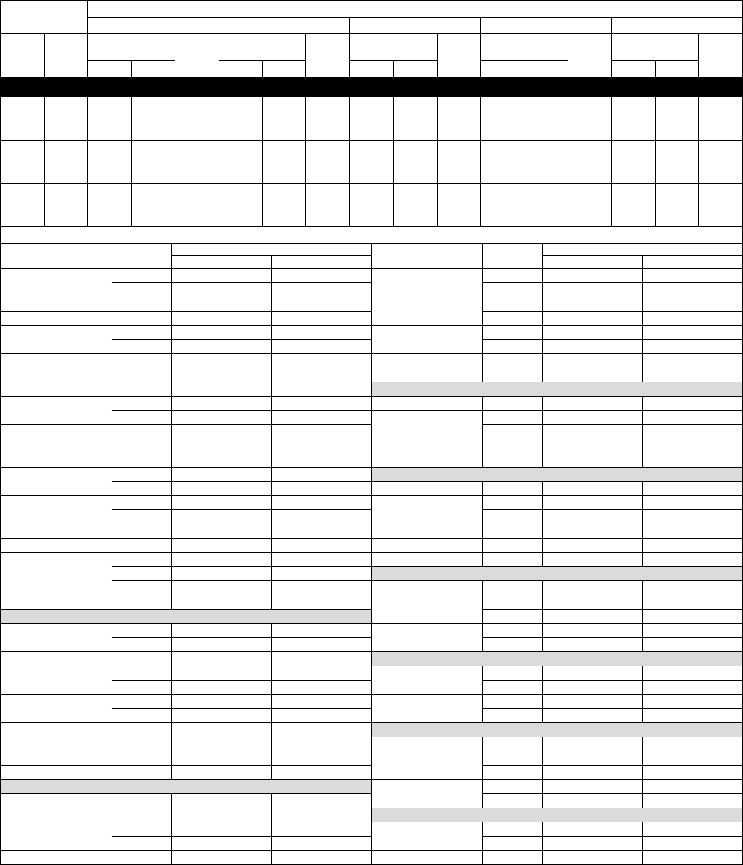
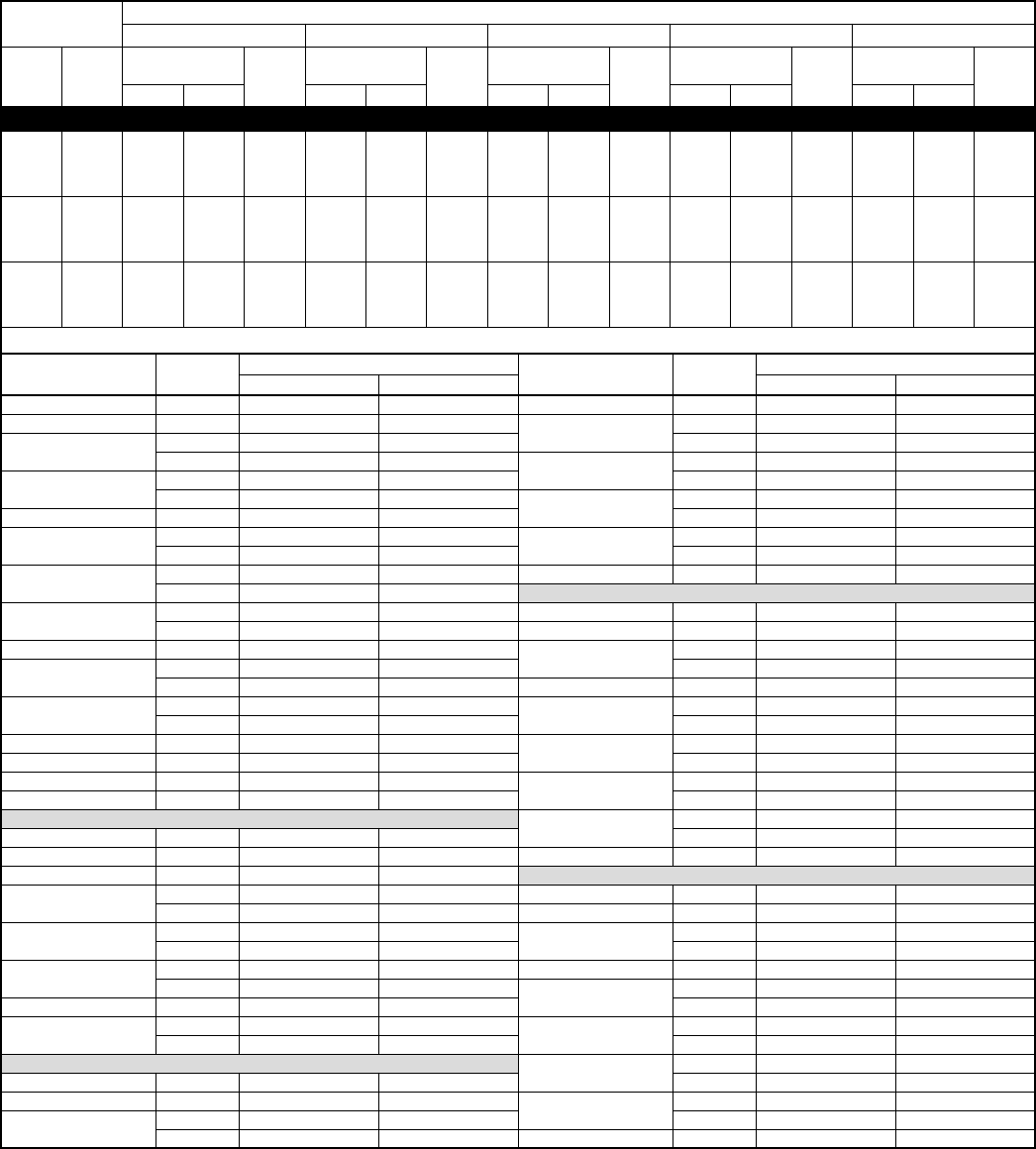
SPECIFICATIONS
See notes on page 5.
UNIT SIZE 018-C, D 024-C, D 030-C, D 036-C, D
Operating Weight (Lb) 137 143 161 169
ELECTRICAL
Unit Volts—Hertz—Phase 208–230—60—1
Operating Voltage Range* 197—253
Compressor—Rated Load Amps 8.6 10.9 13.7 15.0
Locked Rotor Amps 49.0 56.0 75.0 82.0
Condenser Fan Motor—Full Load Amps 0.5 0.5 0.8 1.4
Min Unit Ampacity for Wire Sizing 11.3 14.1 17.9 20.2
Min Wire Size (75°C Copper) AWG†14 14 14 12
Min Wire Size (60°C Copper) AWG†14 14 14 12
Max Wire Length (Ft) (75°C Copper)‡62 50 42 57
Max Wire Length (Ft) (60°C Copper)‡66 53 44 60
Max Branch Circuit Fuse Size** 15 20 25 30
COMPRESSOR and REFRIGERANT
Compressor—Manufacturer and Type Copeland Reciprocating
Temperature and Current Protection Internal Line Break
Refrigerant—Type and Amount (Lb)†† R-22 and 3.88 R-22 and 4.44 R-22 and 4.63 R-22 and 5.50
CONDENSER COIL and FAN
Coil Face (Sq Ft) 7.2 7.2 8.8 10.9
Fins per In.—Rows—Circuits 20—1—125—1—125—1—225—1—2
Fan Motor—HP, Type, and RPM 1/12 PSC and 1100 1/10 PSC and 1100 1/4 PSC and 1100
Volts—Hertz—Phase 208/230—60—1
Condenser Airflow (CFM) 1900 1900 2100 2600
OPTIONAL EQUIPMENT
Support Feet KSASF0101AAA
Coastal Filter KAACF0701SML
Time Delay Relay KAATD0601TDR
Cycle Protector KSACY0101AAA
Crankcase Heater KAACH1001AAA
Start Assist—Capacitor/Relay Type KSAHS1001AAA
Start Assist—PTC Type KAACS0201PTC
Sound Hood KSASH1101COP KSASH1201COP
TXV Kit (RPB) KAATX0201RPB KAATX0301RPB KAATX0401RPB KAATX0501RPB
TXV Kits (Hard Shutoff) KSATX0601HSO
Low-Pressure Switch KAALP0101LPS
High-Pressure Switch KSAHI0101HPS
Filter Drier P502-8083S (RCD)
Evaporator Freeze Thermostat** KAAFT0101AAA
Liquid-Line Solenoid Valve KAALS0101LLS
Winter Start Control** KAAWS0101AAA
Low-Ambient Kit KSALA0201R22
MotorMaster® Control†† 32LT660004 (RCD)
Ball Bearing Fan Motor HC34GE232 (RCD)
Thermostat, Auto Changeover,
Non-Programmable, °F/°C,
1-Stage Heat, 1-Stage Cool TSTATBBNAC01-B
Thermostat, Auto Changeover,
7-Day Programmable, °F/°C,
1-Stage Heat, 1-Stage Cool TSTATBBPAC01-B
Builder’s Thermostat, Manual
Changeover, Non-Programmable,
°F/°C, 1-Stage Heat, 1-Stage Cool TSTATBBBAC01-B
Thermidistat™ Control—Programmable/
Non-Programmable Thermostat with
Humidity Control TSTATBBPRH01-B
Outdoor Air Temperature Sensor TSTATBBSEN01-B
Backplate for Non-Programmable
Thermostat TSTATXXNBP01
Backplate for Programmable Thermostat TSTATXXPBP01
Backplate for Builder’s Thermostat TSTATXXBBP01
Thermostat Conversion Kit (4 to 5 wire)
— 10 Pack TSTATXXCNV10

—5—
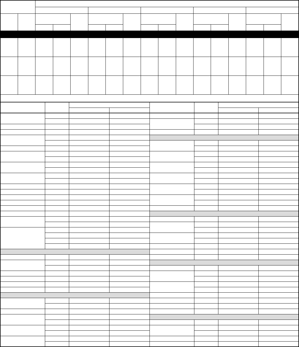
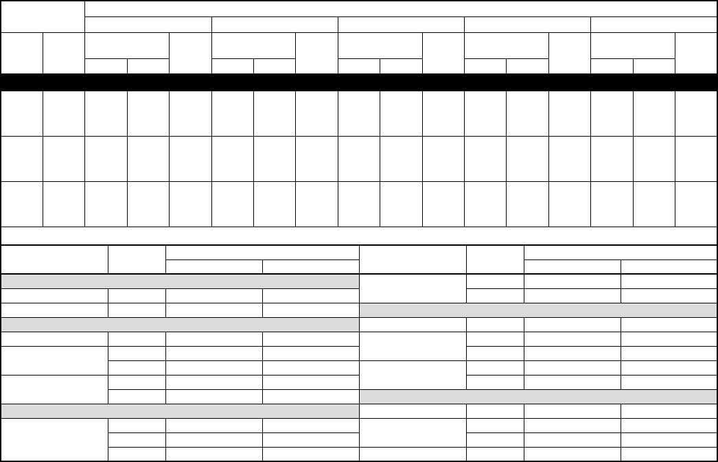
SPECIFICATIONS Continued
* Permissible limits of the voltage range at which the unit will operate satisfactorily. Operation outside these limits may result in unit failure.
†If wire is applied at ambient greater than 30°C (86°F), consult Table 310-16 of the NEC (ANSI/NFPA 70).
The ampacity of nonmetallic-sheathed cable (NM), trade name ROMEX, shall be that of 60°C (140°F) conductors per the NEC (ANSI/NFPA 70) Article
336-26. If other than uncoated (non-plated), 60° or 75°C (140° or 167°F) insulation, copper wire (solid wire for 10 AWG and smaller, stranded wire for
larger than 10 AWG) is used, consult applicable tables of the NEC (ANSI/NFPA 70).
‡Length shown is as measured 1 way along wire path between unit and service panel for a voltage drop not to exceed 2%.
** Fan motor with ball bearings required. See Low-ambient controller Installation Instructions for application.
NOTE: Copper wire must be used from service disconnect to unit. All motors/compressors contain internal overload protection.
UNIT SIZE 042-C, D 048-C 060-C
Operating Weight (Lb) 206 199 217
ELECTRICAL
Unit Volts—Hertz—Phase 208–230—60—1
Operating Voltage Range* 197—253
Compressor—Rated Load Amps 19.0 24.4 28.8
Locked Rotor Amps 105.0 140.0 165.0
Condenser Fan Motor—Full Load Amps 1.4 1.4 1.4
Min Unit Ampacity for Wire Sizing 25.2 31.9 37.4
Min Wire Size (75°C Copper) AWG†10 10 8
Min Wire Size (60°C Copper) AWG†10 8 8
Max Wire Length (Ft) (75°C Copper)‡73 59 78
Max Wire Length (Ft) (60°C Copper)‡77 97 82
Max Branch Circuit Fuse Size** 40 50 60
COMPRESSOR and REFRIGERANT
Compressor—Manufacturer and Type Copeland Reciprocating Millennium Scroll Millennium Scroll
Temperature and Current Protection Internal Line Break Internal Line Break and Dome Thermostat
Refrigerant—Type and Amount (Lb)†† R-22 and 5.51 R-22 and 7.63 R-22 and 10.63
CONDENSER COIL and FAN
Coil Face (Sq Ft) 12.2 15.2 18.3
Fins per In.—Rows—Circuits 20—1—225—1—325—1—4
Fan Motor—HP, Type, and RPM 1/4 PSC and 1100
Volts—Hertz—Phase 208/230—60—1
Condenser Airflow (CFM) 3000
OPTIONAL EQUIPMENT
Support Feet KSASF0101AAA
Coastal Filter KAACF0801MED
Time Delay Relay KAATD0101TDR
Cycle Protector KSACY0101AAA
Crankcase Heater Standard KAACH1201AAA
Start Assist—Capacitor/Relay Type KSAHS1301AAA KSAHS1601AAA
Start Assist—PTC Type KAACS0201PTC
Sound Hood KSASH1201COP KSASH2001CYL
TXV Kit (RPB) KAATX0501RPB KAATX0601RPB KAATX0701RPB
TXV Kits (Hard Shutoff) KSATX0601HSO KSATX0701HSO
Low-Pressure Switch KAALP0101LPS
High-Pressure Switch KSAHI0101HPS
Filter Drier P502-8163S (RCD)
Evaporator Freeze Thermostat** KAAFT0101AAA
Liquid-Line Solenoid Valve KAALS0101LLS
Winter Start Control** KAAWS0101AAA
Low-Ambient Kit KSALA0201R22
MotorMaster® Control†† 32LT660004 (RCD)
Ball Bearing Fan Motor HC40GE232 (RCD)
Thermostat, Auto Changeover,
Non-Programmable, °F/°C,
1-Stage Heat, 1-Stage Cool TSTATBBNAC01-B
Thermostat, Auto Changeover,
7-Day Programmable, °F/°C,
1-Stage Heat, 1-Stage Cool TSTATBBPAC01-B
Builder’s Thermostat, Manual
Changeover, Non-Programmable,
°F/°C, 1-Stage Heat, 1-Stage Cool TSTATBBBAC01-B
Thermidistat™ Control—Programmable/
Non-Programmable Thermostat with
Humidity Control TSTATBBPRH01-B
Outdoor Air Temperature Sensor TSTATBBSEN01-B
Backplate for Non-Programmable
Thermostat TSTATXXNBP01
Backplate for Programmable Thermostat TSTATXXPBP01
Backplate for Builder’s Thermostat TSTATXXBBP01
Thermostat Conversion Kit (4 to 5 wire)
— 10 Pack TSTATXXCNV10
—6—
ACCESSORY DESCRIPTION AND USAGE (Listed Alphabetically)
1. Ball Bearing Fan Motor
A fan motor with ball bearings which permits speed reduction while maintaining bearing lubrication.
SUGGESTED USE: Required on all units where Low-Ambient Controller (full modulation feature) or MotorMaster
®
Control has been added.
2. Coastal Filter
A filter designed to protect the condenser coil from salt damage without restricting airflow through the outdoor coil.
SUGGESTED USE: Geographic areas prone to salt spray. Used to meet job specifications where added coil protection is required.
3. Compressor Start Assist—Capacitor/Relay Type
Start capacitor and start relay gives ‘‘hard’’ boost to compressor motor at each start-up.
SUGGESTED USE: Installations where interconnecting tube length exceeds 50 ft.
Installations where outdoor design temperature exceeds 105°F (40.6°C).
Replacement installations with hard shutoff expansion valve on indoor coil.
Installations where Liquid-Line Solenoid Valve has been added.
4. Compressor Start Assist—PTC Type
Solid-state electrical device which gives a ‘‘soft’’ boost to compressor at each start-up.
SUGGESTED USE: Installations with marginal power supply.
5. Crankcase Heater
An electric resistance heater which mounts to the base of compressor to keep lubricant warm during off cycles. Improves compressor lubrication on
restart and minimizes chance of refrigerant slugging. May or may not include a thermostat control.
SUGGESTED USE: When interconnecting tube length exceeds 50 ft.
When unit will be operated below 55°F (12.8°C) outdoor air temperature. Use with Low-Ambient Controller.
All commercial installations.
6. Cycle Protector
Solid-state timing device which prevents compressor rapid recycling. Control provides an approximate 5-minute delay after power to the compressor has
been interrupted for any reason, including normal room thermostat cycling.
SUGGESTED USE: Installations in areas where power interruptions are frequent.
Where user is likely to ‘‘play’’ with the room thermostat.
All commercial installations.
Installations where interconnecting tube length exceeds 50 ft.
High rise applications.
7. Evaporator Freeze Thermostat
An SPST temperature actuated switch which stops unit operation when evaporator reaches freeze-up conditions.
SUGGESTED USE: All units where Low-Ambient Controller has been added.
8. Filter Drier
A device for removing contaminants from refrigerant circulating in an air conditioner: 1-direction flow.
SUGGESTED USE: All split-system air conditioners.
9. High-Pressure Switch
Auto reset SPST switch activated by refrigerant pressure on high side of refrigerant circuit. Cycles compressor off if refrigerant pressure rises to 400 ± 10
psig and resets at 298 ± 20 psig. Provides additional protection against compressor damage due to loss of outdoor airflow. To prevent rapid compressor
recycling, Cycle Protector can be used with this switch.
SUGGESTED USE: Installations exposed to very ‘‘dirty’’ outdoor air.
Installations where condenser inlet air temperature exceeds 125°F (51.7°C).
10. Liquid-Line Solenoid Valve (LSV)
An electrically operated shutoff valve to be installed at the outdoor or indoor unit (depending on tubing configuration), which stops and starts refrigerant
liquid flow in response to compressor operation. Maintains a column of refrigerant liquid ready for action at next compressor operation cycle.
Note: Compressor Start Assist—Capacitor/Relay Type must also be used. Do not use with hard shutoff TXV.
SUGGESTED USE: For improved system performance in air conditioners for certain combinations of indoor and outdoor units. Refer to ARI Unitary Directory.
In certain long line applications. Refer to Long-Line Application Guideline.
11. Low-Pressure Switch
Auto reset SPST switch activated by refrigerant pressure on low side of refrigerant circuit. Cycles compressor off if refrigerant pressure drops to about 27
psig. Prevents indoor coil freeze-up due to loss of indoor airflow. Also, provides additional protection against compressor damage due to loss of refrigerant
charge. To prevent rapid compressor recycling. Compressor Cycle Protector can be used with this switch.
SUGGESTED USE: Where indoor coil is exposed to ‘‘dirty’’ air.
All commercial installations.
12. MotorMaster
®
Control
A fan speed control device activated by a temperature sensor. Designed to control condenser fan motor speed in response to the saturated, condensing
temperature during operation in cooling mode only. For outdoor temperatures down to –20°F, it maintains condensing temperature at 100°F ±10°F.
SUGGESTED USE: Cooling operation at outdoor temperatures below 55°F.
All commercial installations.
13. Outdoor Air Temperature Sensor
A device that allows the temperature at a remote location (outdoors) to be displayed at the thermostat.
SUGGESTED USE: All corporate programmable thermostats.
14. Sound Hood
Wrap-around sound attenuation cover for the compressor. Reduces the sound level by about 2 decibels.
SUGGESTED USE: Unit installed closer than 15 ft to quiet areas—bedrooms, etc.
Unit installed between 2 houses less than 10 ft apart.
15. Support Feet
Four stick-on plastic feet which raise the unit 4 in. above the mounting pad. This allows sand, dirt, and other debris to be flushed from the unit base;
minimizes corrosion.
SUGGESTED USE: Coastal installations.
Windy areas or where debris is normally circulating.
Rooftop installations.
16. Thermostatic Expansion Valve (TXV) Kits
A modulating flow control valve which meters refrigerant liquid flow rate into the evaporator in response to the superheat of the refrigerant gas leaving the
evaporator. Kit includes valve, adapter tubes, and external equalizer tube. Both hard shutoff and RPB type valves are available. Do not use hard shutoff
TXV with Liquid-Line Solenoid Valve.
SUGGESTED USE: For improved system performance in cooling mode for certain combinations of indoor and outdoor units. Refer to ARI Unitary Directory.
Required for use on all zoning systems.
—7—
ACCESSORY DESCRIPTION AND USE (Listed Alphabetically) Continued
17. Time Delay Relay
An SPST delay relay which briefly continues operation of the indoor blower motor to provide additional cooling after the compressor cycles off.
SUGGESTED USE: For improved efficiency ratings for certain combinations of indoor and outdoor units. Refer to ARI Unitary Directory.
18. Winter Start Control
An SPST delay relay which bypasses the low-pressure switch for approximately 3 minutes to permit start-up for cooling operation under low load
conditions.
SUGGESTED USE: All air conditioners where Low-Ambient Controller has been added.
ACCESSORY USAGE GUIDELINE
* For tubing line sets greater than 50 ft and/or 20 ft vertical differential, refer to Residential Split-system Long-Line Application Guideline and Service Manual.
†Only when low-pressure switch is used.
‡Required for Low-Ambient Controller (full modulation feature) and MotorMaster® Control only.
SOUND POWER (dBA)
ACCESSORY
REQUIRED FOR
LOW-AMBIENT
APPLICATIONS
(Below 55°F)
REQUIRED FOR
LONG-LINE
APPLICATIONS*
(Over 50 Ft)
REQUIRED FOR
SEA COAST
APPLICATIONS
(Within 2 Miles)
Crankcase Heater Yes Yes No
Evaporator Freeze Thermostat Yes No No
Winter Start Control Yes†No No
Accumulator No No No
Compressor Start Assist
Capacitor and Relay Yes Yes No
MotorMaster® Control
or
Low-Ambient Pressure Switch Yes N o No
Wind Baffle See Low-Ambient Instructions No No
Coastal Filter No No Yes
Support Feet Recommended No Recommended
Liquid-Line Solenoid Valve
or
Hard Shutoff TXV No See Long-Line
Application
Guideline No
Ball Bearing Fan Motor Yes‡No No
Unit
Size
Sound
Level
(dBA)
OCTAVE BAND CENTER FREQUENCY (Hz)
125 250 500 1000 2000 4000 8000
018-C, D 76 54.0 63.5 66.0 66.0 65.0 62.5 55.5
024-C, D 78 53.0 69.0 69.5 71.0 68.5 64.5 60.5
030-C, D 80 53.5 64.0 66.5 69.5 69.0 65.0 58.5
036-C, D 80 57.0 65.5 71.0 75.0 71.0 67.5 62.0
042-C, D 80 62.5 69.0 72.0 75.0 72.0 69.5 62.5
048-C 82 63.0 71.0 71.0 72.0 73.5 68.0 63.5
060-C 82 61.5 69.5 71.0 74.5 70.0 69.0 66.0
—8—
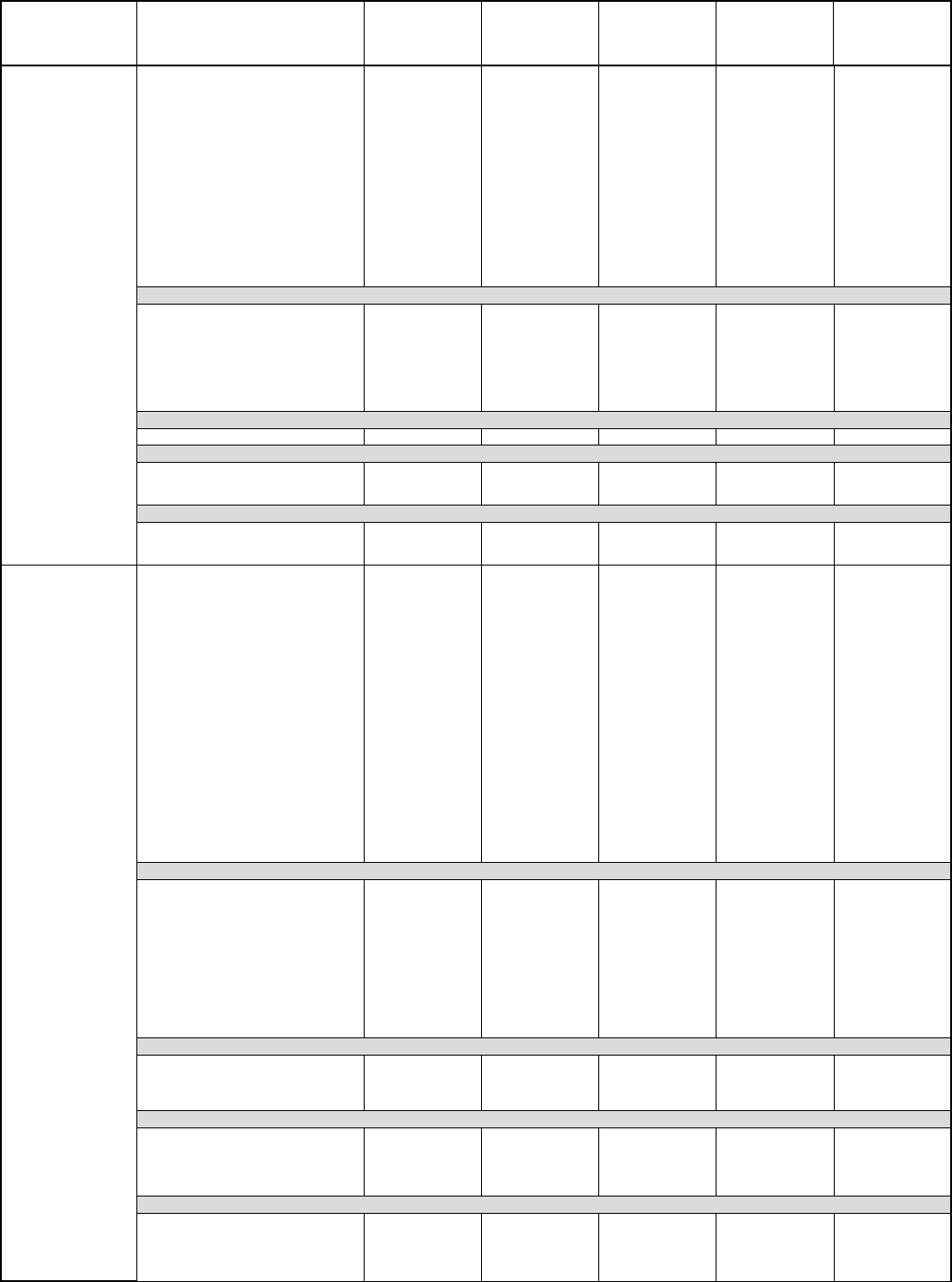
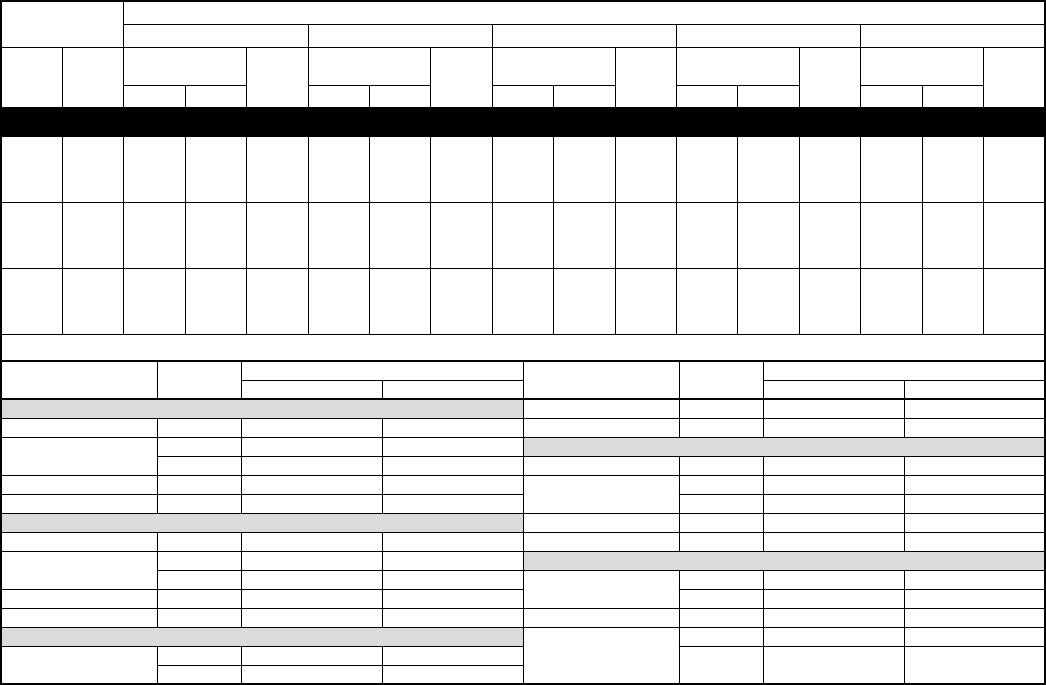
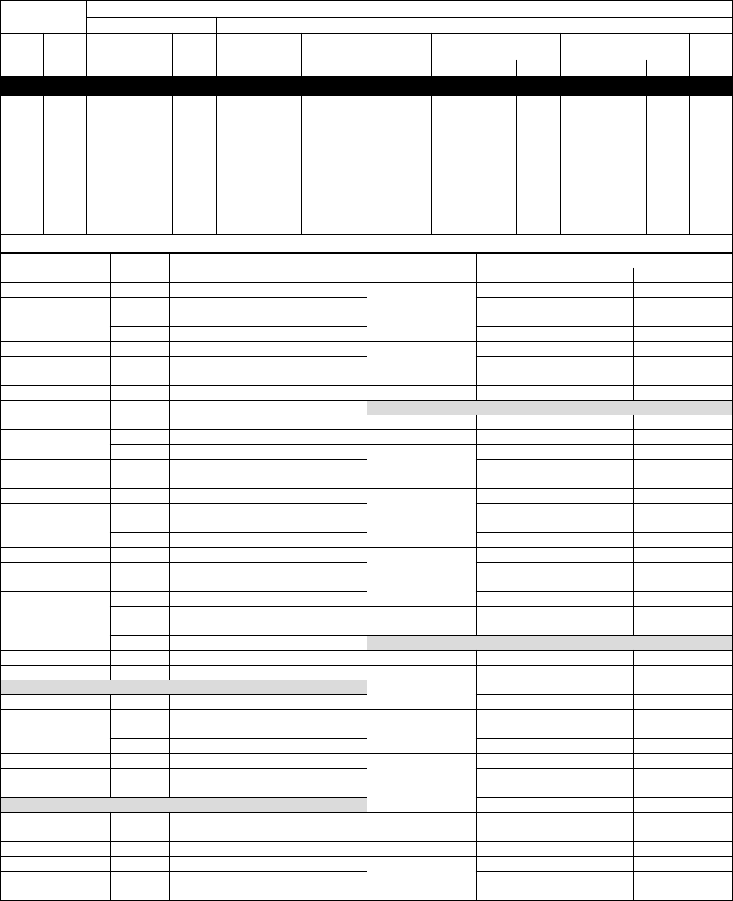
COMBINATION RATINGS
See notes on page 14.
UNIT
SIZE-SERIES
INDOOR
MODEL
TOT.
CAP.
BTUH
FACTORY-
SUPPLIED
ENHANCE-
MENT
STANDARD
RATING
BRYANT GAS
FURNACE OR
ACCESSORY
TDR†
ACCESSORY
TXV‡
018-C, D
CC5A/CD5AA018* 17,200 NONE 10.00 10.50 10.50
CC5A/CD5AA024 17,800 NONE 10.50 11.00 11.00
CC5A/CD5AW024 17,800 NONE 10.50 11.00 11.00
CE3AA024 18,000 NONE 10.50 11.00 11.00
CF5AA024 18,000 NONE 10.50 11.00 11.00
CK3BA024 17,800 NONE 10.50 11.00 11.00
CK5A/CK5BA018 17,200 NONE 10.00 10.50 10.50
CK5A/CK5BA024 17,800 NONE 10.50 11.00 11.00
CK5A/CK5BW024 17,800 NONE 10.50 11.00 11.00
F(A,B)4(A,B)NF018 17,000 TDR 10.00 —10.00
F(A,B)4(A,B)NF024 18,000 TDR 10.50 —10.50
FC4(B,C)NF024 18,000 TDR & TXV 10.50 ——
FF1DNA018 17,000 TDR 10.00 —10.50
FF1DNA024 18,000 TDR 10.20 —10.50
FG3AA024 17,600 NONE 10.20 10.60 10.60
FK4(C,D)NF001 18,000 TDR & TXV 12.00 ——
FK4(C,D)NF002 18,000 TDR & TXV 12.00 ——
COILS + 315(A,J)AV036070 VARIABLE-SPEED FURNACE
CC5A/CD5AA018 17,200 TDR 11 11 10.35
CC5A/CD5AA024 17,600 TDR 11.5 11.5 10.65
CC5A/CD5AW024 17,600 TDR 11.5 11.5 10.65
CE3AA024 17,600 TDR 11.5 11.5 10.65
CK3BA024 17,600 TDR 11.5 11.5 10.85
CK5A/CK5BA018 17,200 TDR 11 11 10.6
CK5A/CK5BA024 17,600 TDR 11.5 11.5 10.85
CK5A/CK5BW024 17,600 TDR 11.5 11.5 10.85
COILS + 355MAV042040 VARIABLE-SPEED FURNACE
CD5A/CD5BA018 17,600 NONE 11.00 —11.00
COILS + 355MAV042060 VARIABLE-SPEED FURNACE
CC5A/CD5AA018 17,600 NONE 11.00 —11.00
CK3BA024 17,600 NONE 11.50 —11.50
CK5A/CK5BW024 17,600 NONE 11.50 —11.50
COILS + 355MAV042080 VARIABLE-SPEED FURNACE
CC5A/CD5AA018 17,600 NONE 11.00 —11.00
CK3BA024 17,600 NONE 11.50 —11.50
CK5A/CK5BW024 17,600 NONE 11.50 —11.50
024-C, D
CC5A/CD5AA024* 23,000 NONE 10.00 10.20 10.20
CC5A/CD5AA030 23,000 NONE 10.00 10.50 10.50
CC5A/CD5AW024 23,000 NONE 10.00 10.20 10.20
CC5A/CD5AW030 23,000 NONE 10.10 10.50 10.50
CE3AA024 23,200 NONE 10.00 10.20 10.20
CE3AA030 23,400 NONE 10.10 10.50 10.50
CF5AA024 23,000 NONE 10.10 10.50 10.50
CK3BA024 23,000 NONE 10.00 10.20 10.20
CK3BA030 23,000 NONE 10.00 10.50 10.50
CK5A/CK5BA024 23,000 NONE 10.00 10.20 10.20
CK5A/CK5BA030 23,000 NONE 10.00 10.50 10.50
CK5A/CK5BW024 23,000 NONE 10.00 10.20 10.20
CK5A/CK5BW030 23,000 NONE 10.00 10.50 10.50
F(A,B)4(A,B)NF024 23,000 TDR 10.00 —10.00
F(A,B)4(A,B)NF030 23,200 TDR 10.20 —10.20
FC4(B,C)NF024 23,000 TDR & TXV 10.00 ——
FC4(B,C)NF030 23,400 TDR & TXV 10.20 ——
FF1DNA024 23,000 TDR 10.00 —10.20
FF1DNA030 23,400 TDR 10.00 —10.20
FG3AAA024 22,400 NONE 10.00 10.20 10.20
FK4(C,D)NF001 24,000 TDR & TXV 11.50 ——
FK4(C,D)NF002 24,000 TDR & TXV 11.50 ——
FK4(C,D)NF003 24,000 TDR & TXV 11.50 ——
COILS + 315(A,J)AV036070 VARIABLE-SPEED FURNACE
CC5A/CD5AA024 22,200 TDR 11 11 9.85
CC5A/CD5AA030 22,400 TDR 11 11 10
CC5A/CD5AW024 22,200 TDR 11 11 9.85
CC5A/CD5AW030 22,400 TDR 11 11 10
CE3AA024 22,200 TDR 11 11 9.9
CE3AA030 22,400 TDR 11 11 10.05
CK3BA024 22,200 TDR 11 11 10
CK3BA030 22,400 TDR 11 11 10
CK5A/CK5BA024 22,200 TDR 11 11 10
CK5A/CK5BA030 22,400 TDR 11 11 10
CK5A/CK5BW024 22,200 TDR 11 11 10
CK5A/CK5BW030 22,400 TDR 11 11 10
COILS + 355MAV042040 VARIABLE-SPEED FURNACE
CC5A/CD5AA024 22,600 NONE 11.00 —11.00
CK3BA024 22,600 NONE 11.00 —11.00
CK3BA030 23,200 NONE 11.20 —11.20
CK5A/CK5BW030 23,200 NONE 11.20 —11.20
COILS + 355MAV042060 VARIABLE-SPEED FURNACE
CC5A/CD5AA024 22,600 NONE 11.00 —11.00
CK3BA024 22,600 NONE 11.00 —11.00
CK3BA030 23,200 NONE 11.20 —11.20
CK5A/CK5BW024 22,600 NONE 11.00 —11.00
CK5A/CK5BW030 23,200 NONE 11.20 —11.20
COILS + 355MAV042080 VARIABLE-SPEED FURNACE
CC5A/CD5AA024 22,600 NONE 11.00 —11.00
CK3BA024 22,600 NONE 11.00 —11.00
CK3BA030 23,200 NONE 11.20 —11.20
CK5A/CK5BW024 22,600 NONE 11.00 —11.00
CK5A/CK5BW030 23,200 NONE 11.20 —11.20
—9—
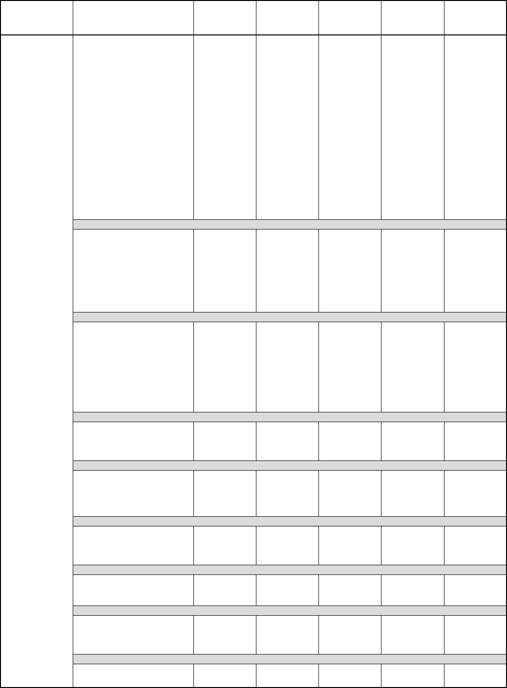
COMBINATION RATINGS Continued
See notes on page 14.
UNIT
SIZE-SERIES
INDOOR
MODEL
TOT.
CAP.
BTUH
FACTORY-
SUPPLIED
ENHANCE-
MENT
STANDARD
RATING
BRYANT GAS
FURNACE OR
ACCESSORY
TDR†
ACCESSORY
TXV‡
030-C, D
CC5A/CD5AA030* 28,600 NONE 10.00 10.20 10.20
CC5A/CD5AA036 29,000 NONE 10.10 10.50 10.50
CC5A/CD5AW030 28,600 NONE 10.00 10.20 10.20
CD5AW036 29,000 NONE 10.10 10.50 10.50
CE3AA030 28,400 NONE 10.00 10.20 10.20
CE3AA036 29,000 NONE 10.10 10.50 10.50
CF5AA036 29,000 NONE 10.10 10.50 10.50
CK3BA030 28,600 NONE 10.00 10.20 10.20
CK3BA036 29,000 NONE 10.10 10.50 10.50
CK5A/CK5BA030 28,600 NONE 10.00 10.20 10.20
CK5A/CK5BA036 29,000 NONE 10.10 10.50 10.50
CK5A/CK5BN036 27,000 NONE 10.10 10.50 10.50
CK5A/CK5BW030 28,600 NONE 10.00 10.20 10.20
CK5A/CK5BW036 29,000 NONE 10.10 10.50 10.50
F(A,B)4(A,B)NF030 28,200 TDR 10.00 —10.00
F(A,B)4(A,B)NF036 28,800 TDR 10.20 —10.20
FC4(B,C)NF030 28,400 TDR & TXV 10.00 ——
FC4(B,C)NF036 28,800 TDR & TXV 10.20 ——
FD3(A,B)NA030 28,400 NONE 10.00 —10.00
FF1DNA030 28,400 TDR 10.00 —10.00
FG3AAA036 29,000 NONE 10.20 10.50 10.50
FK4(C,D)NF001 29,600 TDR & TXV 11.00 ——
FK4(C,D)NF002 29,600 TDR & TXV 11.00 ——
FK4(C,D)NF003 29,600 TDR & TXV 11.20 ——
FK4(C,D)NF005 30,0000 TDR & TXV 11.50 ——
COILS + 315(A,J)AV036070 VARIABLE-SPEED FURNACE
CC5A/CD5AA030 28,000 TDR 11 11 9.75
CC5A/CD5AA036 29,000 TDR 11 11 10.05
CC5A/CD5AW030 28,000 TDR 11 11 9.75
CE3AA030 28,000 TDR 11 11 9.85
CE3AA036 28,600 TDR 11 11 9.9
CK3BA030 28,000 TDR 11 11 9.75
CK3BA036 29,000 TDR 11 11 10.05
CK5A/CK5BA030 28,000 TDR 11 11 9.75
CK5A/CK5BA036 29,000 TDR 11 11 10.05
CK5A/CK5BT036 29,000 TDR 11 11 10.05
CK5A/CK5BW030 28,000 TDR 11 11 9.75
COILS + 315(A,J)AV048090 VARIABLE-SPEED FURNACE
CC5A/CD5AA030 28,000 TDR 11 11 9.85
CC5A/CD5AA036 29,000 TDR 11 11 10.15
CC5A/CD5AW030 28,000 TDR 11 11 9.85
CC5A/CD5AW036 29,000 TDR 11 11 10.15
CE3AA030 28,000 TDR 11 11 9.95
CE3AA036 28,600 TDR 11 11 10.05
CK3BA030 28,000 TDR 11 11 9.85
CK3BA036 29,000 TDR 11 11 10.15
CK5A/CK5BA030 28,000 TDR 11 11 9.85
CK5A/CK5BA036 29,000 TDR 11 11 10.15
CK5A/CK5BW030 28,000 TDR 11 11 9.85
CK5A/CK5BW036 29,000 TDR 11 11 10.15
COILS + 355MAV042040 VARIABLE-SPEED FURNACE
CC5A/CD5AA030 29,000 NONE 11.00 —11.00
CK3BA030 29,000 NONE 10.50 —10.50
CK3BA036 29,000 NONE 10.50 —10.50
CK5A/CK5BW030 29,000 NONE 10.50 —10.50
CK5A/CK5BW036 29,000 NONE 10.50 —10.50
COILS + 355MAV042060 VARIABLE-SPEED FURNACE
CC5A/CD5AA030 29,000 NONE 11.00 —11.00
CK3BA030 29,000 NONE 10.50 —10.50
CK3BA036 29,000 NONE 10.50 —10.50
CK5A/CK5BA036 29,000 NONE 10.50 —10.50
CK5A/CK5BN036 27,000 NONE 10.50 —10.50
CK5A/CK5BW030 29,000 NONE 10.50 —10.50
COILS + 355MAV042080 VARIABLE-SPEED FURNACE
CC5A/CD5AA030 29,000 NONE 11.00 —11.00
CK3BA030 29,000 NONE 10.50 —10.50
CK3BA036 29,000 NONE 10.50 —10.50
CK5A/CK5BW030 29,000 NONE 10.50 —10.50
CK5A/CK5BW036 29,000 NONE 10.50 —10.50
COILS + 355MAV060080 VARIABLE-SPEED FURNACE
CK3BA030 29,000 NONE 10.50 —10.50
CK3BA036 29,000 NONE 10.50 —10.50
CK5A/CK5BW030 29,000 NONE 10.50 —10.50
CK5A/CK5BW036 29,000 NONE 10.50 —10.50
COILS + 355MAV060100 VARIABLE-SPEED FURNACE
CC5A/CD5AA030 29,000 NONE 11.00 —11.00
CK3BA030 29,000 NONE 10.50 —10.50
CK3BA036 29,000 NONE 11.00 —11.00
CK5A/CK5BW030 29,000 NONE 10.50 —10.50
CK5A/CK5BW036 29,000 NONE 11.00 —11.00
COILS + 355MAV060120 VARIABLE-SPEED FURNACE
CK3BA030 29,000 NONE 10.50 —10.50
CK3BA036 29,000 NONE 11.00 —11.00
CK5A/CK5BW036 29,000 NONE 11.00 —11.00
—10—
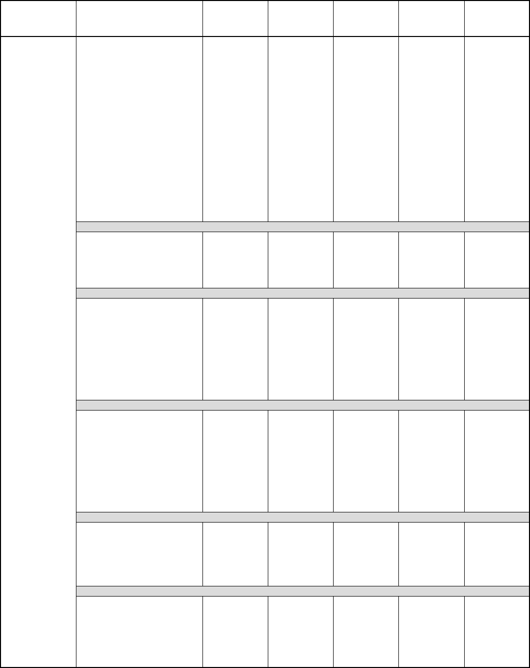
COMBINATION RATINGS Continued
See notes on page 14.
UNIT
SIZE-SERIES
INDOOR
MODEL
TOT.
CAP.
BTUH
FACTORY-
SUPPLIED
ENHANCE-
MENT
STANDARD
RATING
BRYANT GAS
FURNACE OR
ACCESSORY
TDR†
ACCESSORY
TXV‡
036-C, D
CC5A/CD5AA036* 34,600 NONE 10.00 10.20 10.20
CC5A/CD5AA042 34,600 NONE 10.00 10.20 10.20
CC5A/CD5AW042 34,600 NONE 10.00 10.20 10.20
CD5AW036 34,600 NONE 10.00 10.20 10.20
CE3AA036 34,400 NONE 10.00 10.20 10.20
CE3AA042 34,600 NONE 10.10 10.50 10.50
CF5AA036 34,600 NONE 10.10 10.50 10.50
CK3BA036 34,600 NONE 10.00 10.20 10.20
CK3BA042 34,600 NONE 10.00 10.20 10.20
CK5A/CK5BA036 34,600 NONE 10.00 10.20 10.20
CK5A/CK5BA042 34,600 NONE 10.00 10.20 10.20
CK5A/CK5BN036 32,000 NONE 10.00 10.20 10.20
CK5A/CK5BN042 33,600 NONE 10.00 10.20 10.20
CK5A/CK5BW036 34,600 NONE 10.00 10.20 10.20
F(A,B)4(A,B)NF036 34,000 TDR 10.00 —10.00
F(A,B)4(A,B)N(F,B)042 34,800 TDR 10.20 —10.20
FC4(B,C)NF036 34,000 TDR & TXV 10.00 ——
FC4(B,C)N(F,B)042 34,800 TDR & TXV 10.20 ——
FG3AAA036 34,000 NONE 10.00 10.20 10.20
FK4(C,D)NF001 34,600 TDR & TXV 10.20 ——
FK4(C,D)NF002 34,600 TDR & TXV 10.20 ——
FK4(C,D)NF003 34,800 TDR & TXV 10.50 ——
FK4(C,D)NF005 35,400 TDR & TXV 11.00 ——
FK4(C,D)NB006 35,400 TDR & TXV 11.50 ——
COILS + 315(A,J)AV036070 VARIABLE-SPEED FURNACE
CC5A/CD5AA036 33,000 TDR 11 11 9.7
CE3AA036 32,600 TDR 10.5 10.5 9.6
CE3AA042 33,000 TDR 11 11 9.8
CK3BA036 33,000 TDR 11 11 9.7
CK5A/CK5BA036 33,000 TDR 11 11 9.7
CK5A/CK5BE042 33,000 TDR 11 11 9.8
CK5A/CK5BT036 33,000 TDR 11 11 9.7
COILS + 315(A,J)AV048090 VARIABLE-SPEED FURNACE
CC5A/CD5AA036 33,000 TDR 11 11 9.85
CC5A/CD5AA042 33,000 TDR 11 11 9.95
CC5A/CD5AW036 33,000 TDR 11 11 9.85
CE3AA036 32,600 TDR 10.5 10.5 9.75
CE3AA042 33,000 TDR 11 11 9.95
CK3BA036 33,000 TDR 11 11 9.85
CK3BA042 33,000 TDR 11 11 9.9
CK5A/CK5BA036 33,000 TDR 11 11 9.85
CK5A/CK5BA042 33,000 TDR 11 11 9.9
CK5A/CK5BE042 33,000 TDR 11 11 9.95
CK5A/CK5BT036 33,000 TDR 11 11 9.85
CK5A/CK5BT042 33,000 TDR 11 11 9.9
CK5A/CK5BW036 33,000 TDR 11 11 9.85
COILS + 315(A,J)AV066110 VARIABLE-SPEED FURNACE
CC5A/CD5AA036 33,000 TDR 11 11 9.9
CC5A/CD5AA042 33,000 TDR 11 11 10.05
CC5A/CD5AW036 33,000 TDR 11 11 9.9
CC5A/CD5AW042 33,000 TDR 11 11 10
CE3AA036 32,600 TDR 10.5 10.5 9.85
CE3AA042 33,000 TDR 11 11 10
CK3BA036 33,000 TDR 11 11 9.95
CK3BA042 33,000 TDR 11 11 10
CK5A/CK5BA036 33,000 TDR 11 11 9.95
CK5A/CK5BA042 33,000 TDR 11 11 10
CK5A/CK5BT036 33,000 TDR 11 11 9.95
CK5A/CK5BT042 33,000 TDR 11 11 10
CK5A/CK5BW036 33,000 TDR 11 11 9.95
COILS + 315(A,J)AV066135 VARIABLE-SPEED FURNACE
CC5A/CD5AA042 33,000 TDR 11 11 10
CC5A/CD5AW036 33,000 TDR 11 11 9.85
CC5A/CD5AW042 33,000 TDR 11 11 9.95
CE3AA036 32,600 TDR 10.5 10.5 9.8
CE3AA042 33,000 TDR 11 11 9.95
CK3BA042 33,000 TDR 11 11 9.95
CK5A/CK5BA042 33,000 TDR 11 11 9.95
CK5A/CK5BW036 33,000 TDR 11 11 9.9
COILS + 315(A,J)AV066155 VARIABLE-SPEED FURNACE
CC5A/CD5AA042 33,000 TDR 11 11 10.05
CC5A/CD5AW036 33,000 TDR 11 11 9.9
CC5A/CD5AW042 33,000 TDR 11 11 10
CE3AA036 32,600 TDR 10.5 10.5 9.8
CE3AA042 33,000 TDR 11 11 10.05
CK3BA042 33,000 TDR 11 11 10
CK5A/CK5BA042 33,000 TDR 11 11 10
CK5A/CK5BT042 33,000 TDR 11 11 10
CK5A/CK5BW036 33,000 TDR 11 11 9.95
—11—
COMBINATION RATINGS Continued
See notes on page 14.
UNIT
SIZE-SERIES
INDOOR
MODEL
TOT.
CAP.
BTUH
FACTORY-
SUPPLIED
ENHANCE-
MENT
STANDARD
RATING
BRYANT GAS
FURNACE OR
ACCESSORY
TDR†
ACCESSORY
TXV‡
036-C, D
COILS + 355MAV042040 VARIABLE-SPEED FURNACE
CC5A/CD5AA036 34,600 NONE 11.00 —11.00
CK3BA036 34,000 NONE 10.50 —10.50
CK3BA042 34,000 NONE 10.50 —10.50
CK5A/CK5BA042 34,000 NONE 10.50 —10.50
CK5A/CK5BW036 34,000 NONE 10.50 —10.50
COILS + 355MAV042060 VARIABLE-SPEED FURNACE
CC5A/CD5AA036 34,600 NONE 11.00 —11.00
CK3BA036 34,000 NONE 10.50 —10.50
CK3BA042 34,000 NONE 10.50 —10.50
CK5A/CK5BA036 34,000 NONE 10.50 —10.50
CK5A/CK5BN042 33,000 NONE 10.50 —10.50
COILS + 355MAV042080 VARIABLE-SPEED FURNACE
CC5A/CD5AA036 34,600 NONE 11.00 —11.00
CK3BA036 34,000 NONE 10.50 —10.50
CK3BA042 34,000 NONE 10.50 —10.50
CK5A/CK5BA042 34,000 NONE 10.50 —10.50
CK5A/CK5BW036 34,000 NONE 10.50 —10.50
COILS + 355MAV060080 VARIABLE-SPEED FURNACE
CK3BA036 34,000 NONE 10.50 —10.50
CK3BA042 34,000 NONE 10.50 —10.50
CK5A/CK5BA042 34,000 NONE 10.50 —10.50
CK5A/CK5BW036 34,000 NONE 10.50 —10.50
COILS + 355MAV060100 VARIABLE-SPEED FURNACE
CC5A/CD5AA036 34,600 NONE 11.00 —11.00
CK3BA036 34,000 NONE 10.50 —10.50
CK3BA042 34,000 NONE 10.50 —10.50
CK5A/CK5BA042 34,000 NONE 10.50 —10.50
CK5A/CK5BW036 34,000 NONE 10.50 —10.50
COILS + 355MAV060120 VARIABLE-SPEED FURNACE
CK3BA036 34,000 NONE 10.50 —10.50
CK3BA042 34,000 NONE 10.50 —10.50
CK5A/CK5BA042 34,000 NONE 10.50 —10.50
CK5A/CK5BW036 34,000 NONE 10.50 —10.50
042-C, D
CC5A/CD5AA042* 39,500 NONE 10.00 10.20 10.20
CC5A/CD5AC048 39,000 NONE 10.00 10.50 10.50
CC5A/CD5AW042 39,500 NONE 10.00 10.20 10.20
CC5A/CD5AW048 40,000 NONE 10.10 10.50 10.50
CD5AA048 40,000 NONE 10.10 10.50 10.50
CE3AA042 39,500 NONE 10.00 10.20 10.20
CE3AA048 39,500 NONE 10.10 10.50 10.50
CF5AA048 40,000 NONE 10.10 10.50 10.50
CK3BA042 39,500 NONE 10.00 10.20 10.20
CK3BA048 40,000 NONE 10.10 10.50 10.50
CK5A/CK5BA042 39,500 NONE 10.00 10.20 10.20
CK5A/CK5BA048 40,000 NONE 10.10 10.50 10.50
CK5A/CK5BN042 38,500 NONE 10.00 10.20 10.20
CK5A/CK5BN048 39,000 NONE 10.10 10.50 10.50
CK5A/CK5BW048 40,000 NONE 10.10 10.50 10.50
F(A,B)4(A,B)N(F,B)042 39,500 TDR 10.00 —10.00
F(A,B)4(A,B)N(F,B)048 40,500 TDR 10.50 —10.50
FC4(B,C)N(F,B)042 39,500 TDR & TXV 10.00 ——
FC4(B,C)N(F,B)048 40,500 TDR & TXV 10.50 ——
FG3AAA048 40,000 NONE 10.10 10.50 10.50
FK4(C,D)NB006 41,500 TDR & TXV 11.50 ——
FK4(C,D)NF003 40,000 TDR & TXV 11.00 ——
FK4(C,D)NF005 41,000 TDR & TXV 11.20 ——
COILS + 315(A,J)AV048090 VARIABLE-SPEED FURNACE
CC5A/CD5AA042 39,500 TDR 11 11 10.05
CC5A/CD5AC048 39,000 TDR 11 11 10.05
CD5AA048 40,000 TDR 11 11 10.15
CE3AA042 39,500 TDR 11 11 10.1
CE3AA048 40,000 TDR 11 11 10.1
CK3BA042 39,500 TDR 11 11 10.05
CK3BA048 40,000 TDR 11 11 10.15
CK5A/CK5BA042 39,500 TDR 11 11 10.05
CK5A/CK5BA048 40,000 TDR 11 11 10.15
CK5A/CK5BE042 39,500 TDR 11 11 10.1
CK5A/CK5BT042 39,500 TDR 11 11 10.05
CK5A/CK5BT048 40,000 TDR 11 11 10.15
COILS + 315(A,J)AV066110 VARIABLE-SPEED FURNACE
CC5A/CD5AA042 39,500 TDR 11 11 10.1
CC5A/CD5AC048 39,000 TDR 11 11 10.15
CC5A/CD5AW042 39,500 TDR 11 11 10.05
CC5A/CD5AW048 40,000 TDR 11 11 10.25
CD5AA048 40,000 TDR 11 11 10.25
CE3AA042 39,500 TDR 11 11 10.2
CE3AA048 40,000 TDR 11 11 10.2
CK3BA042 39,500 TDR 11 11 10.15
CK3BA048 40,000 TDR 11 11 10.25
—12—
COMBINATION RATINGS Continued
See notes on page 14.
UNIT
SIZE-SERIES
INDOOR
MODEL
TOT.
CAP.
BTUH
FACTORY-
SUPPLIED
ENHANCE-
MENT
STANDARD
RATING
BRYANT GAS
FURNACE OR
ACCESSORY
TDR†
ACCESSORY
TXV‡
042-C, D
CK5A/CK5BA042 39,500 TDR 11 11 10.15
CK5A/CK5BA048 40,000 TDR 11 11 10.25
CK5A/CK5BT042 39,500 TDR 11 11 10.15
CK5A/CK5BT048 40,000 TDR 11 11 10.25
CK5A/CK5BW048 40,000 TDR 11 11 10.25
COILS + 315(A,J)AV066135 VARIABLE-SPEED FURNACE
CC5A/CD5AA042 39,500 TDR 11 11 10.15
CC5A/CD5AC048 39,000 TDR 11 11 10.15
CC5A/CD5AW042 39,500 TDR 11 11 10.05
CC5A/CD5AW048 40,000 TDR 11 11 10.25
CD5AA048 40,000 TDR 11 11 10.3
CE3AA042 39,500 TDR 11 11 10.2
CE3AA048 40,000 TDR 11 11 10.2
CK3BA042 39,500 TDR 11 11 10.15
CK3BA048 40,000 TDR 11 11 10.25
CK5A/CK5BA042 39,500 TDR 11 11 10.15
CK5A/CK5BA048 40,000 TDR 11 11 10.25
CK5A/CK5BT042 39,500 TDR 11 11 10.15
CK5A/CK5BT048 40,000 TDR 11 11 10.25
CK5A/CK5BW048 40,000 TDR 11 11 10.25
COILS + 315(A,J)AV066155 VARIABLE-SPEED FURNACE
CC5A/CD5AA042 39,500 TDR 11 11 10.15
CC5A/CD5AC048 39,000 TDR 11 11 10.2
CC5A/CD5AW042 39,500 TDR 11 11 10.1
CC5A/CD5AW048 40,000 TDR 11 11 10.3
CD5AA048 40,000 TDR 11 11 10.3
CE3AA042 39,500 TDR 11 11 10.2
CE3AA048 40,000 TDR 11 11 10.25
CK3BA042 39,500 TDR 11 11 10.15
CK3BA048 40,000 TDR 11 11 10.3
CK5A/CK5BA042 39,500 TDR 11 11 10.15
CK5A/CK5BA048 40,000 TDR 11 11 10.3
CK5A/CK5BT042 39,500 TDR 11 11 10.15
CK5A/CK5BT048 40,000 TDR 11 11 10.3
CK5A/CK5BW048 40,000 TDR 11 11 10.3
COILS + 355MAV042060 VARIABLE-SPEED FURNACE
CK3BA042 39,500 NONE 10.50 —10.50
CK5A/CK5BN042 38,500 NONE 10.50 —10.50
COILS + 355MAV042080 VARIABLE-SPEED FURNACE
CC5A/CD5AA042 40,000 NONE 11.00 —11.00
CK3BA042 39,500 NONE 10.50 —10.50
CK3BA048 39,500 NONE 10.50 —10.50
CK5A/CK5BA042 39,500 NONE 10.50 —10.50
CK5A/CK5BA048 39,500 NONE 10.50 —10.50
COILS + 355MAV060080 VARIABLE-SPEED FURNACE
CK3BA042 39,500 NONE 10.50 —10.50
CK3BA048 39,500 NONE 10.50 —10.50
CK5A/CK5BA042 39,500 NONE 10.50 —10.50
CK5A/CK5BA048 39,500 NONE 10.50 —10.50
COILS + 355MAV060100 VARIABLE-SPEED FURNACE
CC5A/CD5AA042 40,000 NONE 11.00 —11.00
CK3BA042 39,500 NONE 10.50 —10.50
CK3BA048 39,500 NONE 11.00 —11.00
CK5A/CK5BA042 39,500 NONE 10.50 —10.50
CK5A/CK5BA048 39,500 NONE 11.00 —11.00
COILS + 355MAV060120 VARIABLE-SPEED FURNACE
CK3BA042 39,500 NONE 10.50 —10.50
CK3BA048 39,500 NONE 11.00 —11.00
CK5A/CK5BA042 39,500 NONE 10.50 —10.50
CK5A/CK5BW048 39,500 NONE 11.00 —11.00
048-C
CD5AA048* 46,000 NONE 10.20 10.50 10.50
CC5A/CD5AA060 46,000 NONE 10.20 10.50 10.50
CC5A/CD5AC048 45,000 NONE 10.00 10.20 10.20
CC5A/CD5AW048 46,000 NONE 10.20 10.50 10.50
CC5A/CD5AW060 47,500 NONE 10.50 11.00 11.00
CE3AA048 46,500 NONE 10.20 10.50 10.50
CE3AA060 48,000 NONE 10.30 10.50 10.50
CF5AA048 46,000 NONE 10.30 10.50 10.50
CK5A/CK5BA048 46,000 NONE 10.20 10.50 10.50
CK5A/CK5BA060 46,000 NONE 10.20 10.50 10.50
CK5A/CK5BN048 44,500 NONE 10.20 10.50 10.50
CK5A/CK5BN060 46,000 NONE 10.20 10.50 10.50
CK5A/CK5BW048 46,000 NONE 10.20 10.50 10.50
CK5A/CK5BX060 47,500 NONE 10.50 11.00 11.00
CK3BA048 46,000 NONE 10.20 10.50 10.50
CK3BA060 46,000 NONE 10.20 10.50 10.50
F(A,B)4(A,B)N(F,B)048 46,500 TDR 10.50 —10.50
F(A,B)4(A,B)N(F,B)060 48,000 TDR 10.50 —10.50
—13—
COMBINATION RATINGS Continued
See notes on page 14.
UNIT
SIZE-SERIES
INDOOR
MODEL
TOT.
CAP.
BTUH
FACTORY-
SUPPLIED
ENHANCE-
MENT
STANDARD
RATING
BRYANT GAS
FURNACE OR
ACCESSORY
TDR†
ACCESSORY
TXV‡
048-C
FB4(A,B)NB070 48,000 TDR 11.00 —11.00
FC4(B,C)N(F,B)048 46,500 TDR & TXV 10.40 ——
FC4(B,C)N(F,B)060 47,500 TDR & TXV 10.50 ——
FC4(B,C)NB054 48,000 TDR & TXV 11.00 ——
FC4(B,C)NB070 48,000 TDR & TXV 11.00 ——
FG3AAA048 46,000 NONE 10.00 10.50 10.50
FG3AAA060 47,500 NONE 10.30 10.50 10.50
FK4(C,D)NB006 48,000 TDR & TXV 11.50 ——
FK4(C,D)NF005 47,500 TDR & TXV 11.00 ——
COILS + 315(A,J)AV048090 VARIABLE-SPEED FURNACE
CC5A/CD5AC048 45,500 TDR 10.5 10.5 9.5
CD5AA048 45,500 TDR 10.5 10.5 9.55
CE3AA048 45,500 TDR 10.5 10.5 9.55
CE3AA060 46,500 TDR 11 11 9.85
CK3BA048 45,500 TDR 10.5 10.5 9.6
CK5A/CK5BA048 45,500 TDR 10.5 10.5 9.6
CK5A/CK5BT048 45,500 TDR 10.5 10.5 9.6
COILS + 315(A,J)AV066110 VARIABLE-SPEED FURNACE
CC5A/CD5AA060 46,000 TDR 11 11 9.75
CC5A/CD5AC048 45,500 TDR 10.5 10.5 9.65
CC5A/CD5AW048 45,500 TDR 10.5 10.5 9.7
CD5AA048 45,500 TDR 10.5 10.5 9.7
CE3AA048 45,500 TDR 10.5 10.5 9.75
CE3AA060 46,500 TDR 11 11 10
CK3BA048 45,500 TDR 10.5 10.5 9.75
CK3BA060 46,500 TDR 11 11 9.95
CK5A/CK5BA048 45,500 TDR 10.5 10.5 9.75
CK5A/CK5BA060 46,500 TDR 11 11 9.95
CK5A/CK5BT048 45,500 TDR 10.5 10.5 9.75
CK5A/CK5BT060 46,500 TDR 11 11 9.95
CK5A/CK5BW048 45,500 TDR 10.5 10.5 9.75
CK5A/CK5BX060 47,000 TDR 11 11 10.2
COILS + 315(A,J)AV066135 VARIABLE-SPEED FURNACE
CC5A/CD5AA060 46,000 TDR 11 11 9.75
CC5A/CD5AC048 45,500 TDR 10.5 10.5 9.6
CC5A/CD5AW048 45,500 TDR 10.5 10.5 9.7
CC5A/CD5AW060 46,500 TDR 11 11 10
CD5AA048 45,500 TDR 10.5 10.5 9.7
CE3AA048 45,500 TDR 10.5 10.5 9.7
CE3AA060 46,500 TDR 11 11 10
CK3BA048 45,500 TDR 10.5 10.5 9.7
CK3BA060 46,500 TDR 11 11 9.95
CK5A/CK5BA048 45,500 TDR 10.5 10.5 9.7
CK5A/CK5BA060 46,500 TDR 11 11 9.95
CK5A/CK5BT048 45,500 TDR 10.5 10.5 9.7
CK5A/CK5BT060 46,500 TDR 11 11 9.95
CK5A/CK5BW048 45,500 TDR 10.5 10.5 9.7
CK5A/CK5BX060 47,000 TDR 11 11 10.15
COILS + 315(A,J)AV066155 VARIABLE-SPEED FURNACE
CC5A/CD5AA060 46,000 TDR 11 11 9.8
CC5A/CD5AC048 45,500 TDR 11 11 9.7
CC5A/CD5AW048 45,500 TDR 11 11 9.75
CC5A/CD5AW060 46,500 TDR 11 11 10.05
CD5AA048 45,500 TDR 11 11 9.75
CE3AA048 45,500 TDR 10.5 10.5 9.75
CE3AA060 46,500 TDR 11 11 10.05
CK3BA048 45,500 TDR 10.5 10.5 9.75
CK3BA060 46,500 TDR 11 11 10
CK5A/CK5BA048 45,500 TDR 10.5 10.5 9.75
CK5A/CK5BA060 46,500 TDR 11 11 10
CK5A/CK5BT048 45,500 TDR 10.5 10.5 9.75
CK5A/CK5BT060 46,500 TDR 11 11 10
CK5A/CK5BW048 45,500 TDR 10.5 10.5 9.75
CK5A/CK5BX060 47,000 TDR 11 11 10.2
COILS + 355MAV042080 VARIABLE-SPEED FURNACE
CK3BA048 45,000 NONE 10.50 —10.50
CK3BA060 45,500 NONE 10.50 —10.50
CK5A/CK5BA048 45,000 NONE 10.50 —10.50
COILS + 355MAV060080 VARIABLE-SPEED FURNACE
CK3BA060 45,500 NONE 10.50 —10.50
CK5A/CK5BA060 45,500 NONE 10.50 —10.50
CK5A/CK5BN060 45,500 NONE 10.50 —10.50
CK5A/CK5BX060 47,000 NONE 11.00 —11.00
COILS + 355MAV060100 VARIABLE-SPEED FURNACE
CC5A/CD5AW060 46,500 NONE 11.00 —11.00
CK3BA048 45,000 NONE 10.50 —10.50
CK3BA060 45,500 NONE 11.00 —11.00
CK5A/CK5BA048 45,000 NONE 10.50 —10.50
CK5A/CK5BA060 45,500 NONE 11.00 —11.00
CK5A/CK5BX060 47,000 NONE 11.00 —11.00
COILS + 355MAV060120 VARIABLE-SPEED FURNACE
CK3BA048 45,000 NONE 10.50 —10.50
CK3BA060 45,500 NONE 11.00 —11.00
CK5A/CK5BA060 45,500 NONE 11.00 —11.00
CK5A/CK5BW048 45,000 NONE 10.50 —10.50
CK5A/CK5BX060 47,000 NONE 11.00 —11.00

—14—
COMBINATION RATINGS Continued
* Tested combination.
†In most cases, only 1 method should be used to achieve TDR function. Using more than 1 method in a system may cause degradation in performance. Use
either the accessory Time-Delay Relay KAATD0101TDR or a furnace equipped with TDR. Most Bryant furnaces are equipped with TDR.
‡Based on computer simulation, TXV must be hard shutoff type.
NOTES: 1. Ratings are net values reflecting the effects of circulating fan motor heat. Supplemental electric heat is not included.
2. Tested outdoor/indoor combinations have been tested in accordance with DOE test procedures for central air conditioners. Ratings for other com-
binations are determined under DOE computer simulation procedures.
3. Determine actual CFM values obtainable for your system by referring to fan performance data in fan coil or furnace coil literature.
UNIT
SIZE-SERIES
INDOOR
MODEL
TOT.
CAP.
BTUH
FACTORY-
SUPPLIED
ENHANCE-
MENT
STANDARD
RATING
BRYANT GAS
FURNACE OR
ACCESSORY
TDR†
ACCESSORY
TXV‡
060-C
CC5A/CD5AW060* 57,000 NONE 10.20 10.50 10.50
CC5A/CD5AA060 54,500 NONE 10.00 10.20 10.20
CE3AA060 57,500 NONE 10.20 10.50 10.50
CK3BA060 54,500 NONE 10.00 10.20 10.20
CK5A/CK5BA060 54,500 NONE 10.00 10.20 10.20
CK5A/CK5BN060 54,500 NONE 10.00 10.20 10.20
CK5A/CK5BX060 57,000 NONE 10.20 10.50 10.50
F(A,B)4(A,B)N(F,B)060 57,500 TDR 10.00 —10.00
FB4(A,B)NB070 58,500 TDR 10.50 —10.50
FC4(B,C)NB070 58,500 TDR & TXV 10.50 ——
FC4(B,C)N(F,B)060 57,500 TDR & TXV 10.00 ——
FG3AAA060 56,500 NONE 10.20 10.50 10.50
FK4(C,D)NB006 58,000 TDR & TXV 11.00 ——
COILS + 315(A,J)AV066110 VARIABLE-SPEED FURNACE
CC5A/CD5AA060 55,000 TDR 10.5 10.5 9
CE3AA060 56,500 TDR 10.5 10.5 9.3
CK3BA060 56,000 TDR 10.5 10.5 9.15
CK5A/CK5BA060 56,000 TDR 10.5 10.5 9.15
CK5A/CK5BT060 56,000 TDR 10.5 10.5 9.15
CK5A/CK5BX060 56,500 TDR 10.5 10.5 9.4
COILS + 315(A,J)AV066135 VARIABLE-SPEED FURNACE
CC5A/CD5AA060 55,000 TDR 10.5 10.5 9
CC5A/CD5AW060 56,000 TDR 10.5 10.5 9.25
CE3AA060 56,500 TDR 10.5 10.5 9.3
CK3BA060 56,000 TDR 10.5 10.5 9.15
CK5A/CK5BA060 56,000 TDR 10.5 10.5 9.15
CK5A/CK5BT060 56,000 TDR 10.5 10.5 9.15
CK5A/CK5BX060 56,500 TDR 10.5 10.5 9.4
COILS + 315(A,J)AV066155 VARIABLE-SPEED FURNACE
CC5A/CD5AA060 55,000 TDR 10.5 10.5 9.1
CC5A/CD5AW060 56,000 TDR 10.5 10.5 9.3
CE3AA060 56,500 TDR 10.5 10.5 9.35
CK3BA060 56,000 TDR 10.5 10.5 9.2
CK5A/CK5BA060 56,000 TDR 10.5 10.5 9.2
CK5A/CK5BT060 56,000 TDR 10.5 10.5 9.2
CK5A/CK5BX060 56,500 TDR 10.5 10.5 9.45
—15—
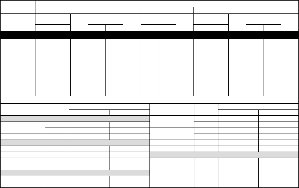
DETAILED COOLING CAPACITIES*
See notes on page 24.
EVAPORATOR
AIR
CONDENSER ENTERING AIR TEMPERATURES °F
85 95 105 115 125
CFM EWB
Capacity
MBtuh†Total
System
kW**
Capacity
MBtuh†Total
System
kW**
Capacity
MBtuh†Total
System
kW**
Capacity
MBtuh†Total
System
kW**
Capacity
MBtuh†Total
System
kW**Total Sens‡Total Sens‡Total Sens‡Total Sens‡Total Sens‡
593C018-C, D Outdoor Section With CC5A/CD5AA018 Indoor Section
525
72 19.7 9.50 1.69 18.6 9.09 1.80 17.5 8.66 1.91 16.3 8.23 2.01 15.2 7.80 2.12
67 17.9 11.8 1.65 16.8 11.4 1.75 15.8 10.9 1.85 14.7 10.5 1.94 13.6 10.0 2.04
62 16.1 14.0 1.60 15.1 13.6 1.70 14.1 13.0 1.79 13.1 12.5 1.88 12.1 12.0 1.96
57 15.0 15.0 1.58 14.3 14.3 1.68 13.5 13.5 1.77 12.8 12.8 1.86 12.0 12.0 1.95
600
72 20.1 9.89 1.73 19.0 9.47 1.84 17.8 9.03 1.95 16.6 8.60 2.06 15.4 8.17 2.16
67 18.3 12.5 1.68 17.2 12.0 1.79 16.1 11.6 1.89 15.0 11.1 1.99 13.8 10.6 2.08
62 16.5 14.9 1.64 15.5 14.4 1.74 14.4 13.8 1.83 13.4 13.2 1.92 12.4 12.4 2.01
57 15.7 15.7 1.62 14.9 14.9 1.72 14.1 14.1 1.82 13.3 13.3 1.91 12.5 12.5 2.01
675
72 20.5 10.3 1.76 19.3 9.83 1.88 18.1 9.39 1.99 16.9 8.95 2.09 15.6 8.51 2.20
67 18.6 13.1 1.72 17.5 12.6 1.83 16.3 12.2 1.93 15.2 11.7 2.03 14.0 11.2 2.13
62 16.8 15.8 1.68 15.8 15.2 1.78 14.7 14.5 1.87 13.7 13.7 1.97 12.7 12.7 2.06
57 16.2 16.2 1.67 15.4 15.4 1.77 14.6 14.6 1.87 13.7 13.7 1.97 12.9 12.9 2.06
Multipliers for Determining the Performance With Other Indoor Sections
Indoor
Section
Unit
Size
Cooling Indoor
Section
Unit
Size
Cooling
Capacity Power Capacity Power
CC5A/CD5AA 018 1.00 1.00 COILS + 315(A,J)AV036070 VARIABLE-SPEED FURNACE
024 1.03 1.01 CC5A/CD5AA 018 1.00 0.91
CC5A/CD5AA 024 1.03 1.01 024 1.02 0.91
CE3AA 024 1.05 1.01 CC5A/CD5AW 024 1.02 0.91
CF5AA 024 1.05 1.01 CE3AA 024 1.02 0.91
CK3BA 024 1.03 1.01 CK3BA 024 1.02 0.89
CK5A/CK5BA 018 1.00 1.01 CK5A/CK5BA 018 1.00 0.89
024 1.03 1.01 024 1.02 0.89
CK5A/CK5BW 024 1.03 1.01 CK5A/CK5BW 024 1.02 0.89
F(A,B)4(A,B)NF 018 0.99 1.00 COILS + 355MAV042040 VARIABLE-SPEED FURNACE
024 1.05 1.02 CC5A/CD5AA 018 1.02 0.93
FC4(B,C)NF 024 1.05 1.02 COILS + 355MAV042060 VARIABLE-SPEED FURNACE
FF1DNA 018 0.99 1.00 CC5A/CD5AA 018 1.02 0.93
024 1.05 1.02 CK5A/CK5BW 024 1.02 0.94
FG3AA 024 1.02 1.01 CK3BA 024 1.02 0.94
FK4(C,D)NF 001 1.05 0.94 COILS + 355MAV042080 VARIABLE-SPEED FURNACE
002 1.05 0.94 CC5A/CD5AA 018 1.02 0.93
—— — CK3BA 024 1.02 0.94
—— —CK5A/CK5BW 024 1.02 0.94
—16—
DETAILED COOLING CAPACITIES* Continued
See notes on page 24.
EVAPORATOR
AIR
CONDENSER ENTERING AIR TEMPERATURES °F
85 95 105 115 125
CFM EWB
Capacity
MBtuh†Total
System
kW**
Capacity
MBtuh†Total
System
kW**
Capacity
MBtuh†Total
System
kW**
Capacity
MBtuh†Total
System
kW**
Capacity
MBtuh†Total
System
kW**Total Sens‡Total Sens‡Total Sens‡Total Sens‡Total Sens‡
593C024-C, D Outdoor Section With CC5A/CD5AA024 Indoor Section
700
72 26.3 12.9 2.34 24.8 12.3 2.49 23.3 11.8 2.62 21.8 11.2 2.75 20.3 10.7 2.88
67 24.0 16.2 2.27 22.6 15.6 2.40 21.2 15.0 2.53 19.8 14.4 2.65 18.3 13.8 2.77
62 21.7 19.3 2.20 20.4 18.7 2.32 19.1 18.0 2.43 17.8 17.3 2.54 16.5 16.5 2.66
57 20.5 20.5 2.17 19.5 19.5 2.28 18.5 18.5 2.41 17.5 17.5 2.53 16.5 16.5 2.65
800
72 26.8 13.4 2.40 25.3 12.9 2.54 23.8 12.3 2.68 22.2 11.8 2.82 20.6 11.2 2.94
67 24.5 17.1 2.33 23.0 16.5 2.46 21.6 15.9 2.59 20.1 15.4 2.71 18.6 14.8 2.82
62 22.2 20.6 2.26 20.9 19.9 2.38 19.5 19.1 2.49 18.2 18.2 2.61 17.1 17.1 2.73
57 21.4 21.4 2.23 20.3 20.3 2.36 19.3 19.3 2.48 18.2 18.2 2.61 17.1 17.1 2.73
900
72 27.4 14.4 2.50 25.9 13.9 2.65 24.3 13.3 2.79 22.7 12.8 2.93 21.0 12.2 3.06
67 25.1 18.9 2.43 23.6 18.3 2.57 22.1 17.7 2.70 20.5 17.1 2.81 18.9 16.4 2.93
62 23.0 22.7 2.37 21.7 21.6 2.50 20.4 20.4 2.63 19.2 19.2 2.75 18.0 18.0 2.88
57 22.7 22.7 2.36 21.6 21.6 2.49 20.4 20.4 2.62 19.2 19.2 2.75 18.0 18.0 2.88
Multipliers for Determining the Performance With Other Indoor Sections
Indoor
Section
Unit
Size
Cooling Indoor
Section
Unit
Size
Cooling
Capacity Power Capacity Power
CC5A/CD5AA 024 1.00 1.00 CC5A/CD5AW 024 0.99 0.91
030 1.00 1.00 030 1.00 0.90
CC5A/CD5AW 024 1.00 1.00 CE3AA 024 0.99 0.91
030 1.00 1.00 030 1.00 0.90
CE3AA 024 1.01 1.00 CK3BA 024 0.99 0.90
030 1.02 1.01 030 1.00 0.90
CF5AA 024 1.00 1.00 CK5A/CK5BA 024 0.99 0.90
CK3BA 024 1.00 1.00 030 1.00 0.90
030 1.00 1.01 CK5A/CK5BW 024 0.99 0.90
CK5A/CK5BA 024 1.00 1.00 030 1.00 0.90
030 1.00 1.01 COILS + 355MAV042040 VARIABLE-SPEED FURNACE
CK5A/CK5BW 024 1.00 1.00 CC5A/CD5AA 024 0.98 0.93
030 1.00 1.01 CK3BA 024 0.98 0.95
F(A,B)4(A,B)NF 024 1.00 1.00 030 1.01 0.95
030 1.01 1.00 CK5A/CK5BW 030 1.01 0.95
FC4(B,C)NF 024 1.00 1.00 COILS + 355MAV042060 VARIABLE-SPEED FURNACE
030 1.02 1.00 CC5A/CD5AA 024 0.98 0.93
FF1DNA 024 1.00 1.01 CK3BA 024 0.98 0.95
030 1.02 1.02 030 1.01 0.95
FG3AAA 024 0.97 1.00 CK5A/CK5BW 024 0.98 0.95
FK4(C,D)NF 001 1.04 0.95 030 1.01 0.95
002 1.04 0.95 COILS + 355MAV042080 VARIABLE-SPEED FURNACE
003 1.04 0.93 CC5A/CD5AA 024 0.98 0.93
COILS + 315(A,J)AV036070 VARIABLE-SPEED FURNACE CK3BA 024 0.98 0.93
CC5A/CD5AA 024 0.99 0.91 030 1.01 0.94
030 1.00 0.90 CK5A/CK5BW 024 0.98 0.93
—— — 030 1.01 0.94
—17—
DETAILED COOLING CAPACITIES* Continued
See notes on page 24.
EVAPORATOR
AIR
CONDENSER ENTERING AIR TEMPERATURES °F
85 95 105 115 125
CFM EWB
Capacity
MBtuh†Total
System
kW**
Capacity
MBtuh†Total
System
kW**
Capacity
MBtuh†Total
System
kW**
Capacity
MBtuh†Total
System
kW**
Capacity
MBtuh†Total
System
kW**Total Sens‡Total Sens‡Total Sens‡Total Sens‡Total Sens‡
593C030-C, D Outdoor Section With CC5A/CD5AA030 Indoor Section
875
72 32.6 15.9 2.90 30.8 15.2 3.11 29.0 14.6 3.30 27.2 13.9 3.49 25.3 13.2 3.67
67 29.7 20.0 2.83 28.1 19.3 3.01 26.4 18.5 3.19 24.6 17.8 3.35 22.9 17.2 3.52
62 26.9 23.9 2.74 25.3 23.1 2.90 23.7 22.3 3.07 22.2 21.4 3.22 20.7 20.5 3.37
57 25.4 25.4 2.69 24.2 24.2 2.86 23.0 23.0 3.03 21.8 21.8 3.20 20.5 20.5 3.37
1000
72 33.2 16.6 2.97 31.4 15.9 3.18 29.5 15.2 3.37 27.6 14.5 3.57 25.6 13.8 3.74
67 30.4 21.2 2.89 28.6 20.4 3.08 26.8 19.7 3.26 25.0 19.0 3.43 23.3 18.3 3.60
62 27.5 25.4 2.81 25.9 24.6 2.98 24.3 23.6 3.14 22.7 22.6 3.30 21.3 21.3 3.47
57 26.5 26.5 2.77 25.2 25.2 2.95 23.9 23.9 3.13 22.6 22.6 3.30 21.3 21.3 3.47
1125
72 33.7 17.2 3.03 31.8 16.5 3.24 29.8 15.8 3.44 27.8 15.1 3.63 25.9 14.4 3.82
67 30.8 22.3 2.95 29.0 21.5 3.15 27.2 20.8 3.33 25.3 20.1 3.50 23.5 19.3 3.67
62 28.0 26.8 2.87 26.3 25.8 3.04 24.7 24.7 3.21 23.3 23.3 3.39 21.9 21.9 3.56
57 27.4 27.4 2.85 26.0 26.0 3.03 24.7 24.7 3.21 23.3 23.3 3.39 21.9 21.9 3.57
Multipliers for Determining the Performance With Other Indoor Sections
Indoor
Section
Unit
Size
Cooling Indoor
Section
Unit
Size
Cooling
Capacity Power Capacity Power
CC5A/CD5AA 030 1.00 1.00 CE3AA 030 1.00 0.92
036 1.01 1.01 036 1.02 0.93
CC5A/CD5AW 030 1.00 1.00 CK3BA 030 1.00 0.93
CD5AW 036 1.01 1.01 036 1.04 0.93
CE3AA 030 0.99 1.00 CK5A/CK5BA 030 1.00 0.93
036 1.01 1.01 036 1.04 0.93
CF5AA 036 1.01 1.01 CK5A/CK5BW 030 1.00 0.93
CK3BA 030 1.00 1.00 036 1.04 0.93
036 1.01 1.01 COILS + 355MAV042040 VARIABLE-SPEED FURNACE
CK5A/CK5BA 030 1.00 1.00 CC5A/CD5AA 030 1.01 0.95
036 1.01 1.01 CK3BA 030 1.01 0.97
CK5A/CK5BN 036 0.94 1.01 036 1.01 0.97
CK5A/CK5BW 030 1.00 1.00 CK5A/CK5BW 030 1.01 0.97
036 1.01 1.01 036 1.01 0.97
F(A,B)4(A,B)NF 030 0.99 1.00 COILS + 355MAV042060 VARIABLE-SPEED FURNACE
036 1.01 1.02 CC5A/CD5AA 030 1.01 0.95
FC4(B,C)NF 030 0.99 1.00 CK3BA 030 1.01 0.97
036 1.01 1.02 036 1.01 0.98
FF1DNA 030 0.99 1.01 CK5A/CK5BA 036 1.01 0.98
FG3AAA 036 1.01 1.00 CK5A/CK5BN 036 0.94 0.98
FK4(C,D)NF 001 1.03 0.97 CK5A/CK5BW 030 1.01 0.97
002 1.03 0.97 COILS + 355MAV042080 VARIABLE-SPEED FURNACE
003 1.03 0.97 CC5A/CD5AA 030 1.01 0.95
005 1.05 0.94 CK3BA 030 1.01 0.97
COILS + 315(A,J)AV036070 VARIABLE-SPEED FURNACE 036 1.01 0.97
CC5A/CD5AA 030 1.00 0.94 CK5A/CK5BW 030 1.01 0.97
036 1.04 0.95 036 1.01 0.97
CC5A/CD5AW 030 1.00 0.94 COILS + 355MAV060080 VARIABLE-SPEED FURNACE
CE3AA 030 1.00 0.93 CK3BA 030 1.01 0.97
036 1.02 0.95 036 1.01 0.98
CK3BA 030 1.00 0.94 CK5A/CK5BW 030 1.01 0.97
036 1.04 0.94 036 1.01 0.98
CK5A/CK5BA 030 1.00 0.94 COILS + 355MAV060100 VARIABLE-SPEED FURNACE
036 1.04 0.94 CC5A/CD5AA 030 1.01 0.95
CK5A/CK5BT 036 1.04 0.94 CK3BA 030 1.01 0.95
CK5A/CK5BW 030 1.00 0.94 036 1.01 0.96
COILS + 315(A,J)AV048090 VARIABLE-SPEED FURNACE CK5A/CK5BW 030 1.01 0.95
CC5A/CD5AA 030 1.00 0.93 036 1.01 0.96
036 1.04 0.93 COILS + 355MAV060120 VARIABLE-SPEED FURNACE
CC5A/CD5AW 030 1.00 0.93 CK3BA 030 1.01 0.95
036 1.04 0.93 036 1.01 0.96
—— —CK5A/CK5BW 036 1.01 0.96
—18—
DETAILED COOLING CAPACITIES* Continued
See notes on page 24.
EVAPORATOR
AIR
CONDENSER ENTERING AIR TEMPERATURES °F
85 95 105 115 125
CFM EWB
Capacity
MBtuh†Total
System
kW**
Capacity
MBtuh†Total
System
kW**
Capacity
MBtuh†Total
System
kW**
Capacity
MBtuh†Total
System
kW**
Capacity
MBtuh†Total
System
kW**Total Sens‡Total Sens‡Total Sens‡Total Sens‡Total Sens‡
593C036-C, D Outdoor Section With CC5A/CD5AA036 Indoor Section
1050
72 39.6 19.6 3.42 37.4 18.8 3.65 35.2 18.0 3.88 32.9 17.2 4.08 30.5 16.4 4.28
67 36.0 24.9 3.32 34.0 24.0 3.54 31.9 23.2 3.75 29.8 22.3 3.94 27.7 21.5 4.12
62 32.7 29.8 3.23 30.7 28.9 3.43 28.8 27.8 3.62 27.0 26.7 3.79 25.3 25.3 3.98
57 31.3 31.3 3.19 29.8 29.8 3.39 28.3 28.3 3.59 26.8 26.8 3.79 25.3 25.3 3.98
1200
72 40.3 20.5 3.49 38.1 19.7 3.73 35.8 18.9 3.96 33.3 18.1 4.17 31.0 17.3 4.38
67 36.7 26.4 3.40 34.6 25.5 3.62 32.4 24.7 3.83 30.3 23.9 4.03 28.1 23.0 4.21
62 33.4 31.8 3.31 31.4 30.7 3.51 29.5 29.4 3.71 27.8 27.8 3.90 26.2 26.2 4.10
57 32.6 32.6 3.29 31.1 31.1 3.50 29.5 29.5 3.71 27.8 27.8 3.90 26.2 26.2 4.10
1350
72 40.8 21.4 3.56 38.5 20.6 3.80 36.1 19.7 4.03 33.6 18.9 4.25 31.4 18.1 4.47
67 37.2 27.9 3.47 35.0 27.0 3.69 32.8 26.1 3.91 30.6 25.3 4.11 28.3 24.3 4.29
62 34.0 33.5 3.38 32.1 32.1 3.59 30.4 30.4 3.80 28.6 28.6 4.00 26.9 26.9 4.20
57 33.7 33.7 3.38 32.1 32.1 3.59 30.4 30.4 3.80 28.6 28.6 4.00 26.9 26.9 4.21
Multipliers for Determining the Performance With Other Indoor Sections
Indoor
Section
Unit
Size
Cooling Indoor
Section
Unit
Size
Cooling
Capacity Power Capacity Power
CC5A/CD5AA 036 1.00 1.00 CK5A/CK5BE 042 0.99 0.91
042 1.00 1.00 CK5A/CK5BT 036 0.99 0.92
CC5A/CD5AW 042 1.00 1.00 042 0.99 0.92
CD5AW 036 1.00 1.00 CK5A/CK5BW 036 0.99 0.92
CE3AA 036 0.99 1.00 COILS + 315(A,J)AV066110 VARIABLE-SPEED FURNACE
042 1.00 1.00 CC5A/CD5AA 036 0.99 0.92
CF5AA 036 1.00 1.00 042 0.99 0.91
CK3BA 036 1.00 1.00 CC5A/CD5AW 036 0.99 0.92
042 1.00 1.00 042 0.99 0.91
CK5A/CK5BA 036 1.00 1.00 CE3AA 036 0.98 0.91
042 1.00 1.00 042 0.99 0.91
CK5A/CK5BN 036 0.92 0.97 CK3BA 036 0.99 0.92
042 0.97 1.00 042 0.99 0.91
CK5A/CK5BW 036 1.00 1.00 CK5A/CK5BA 036 0.99 0.92
F(A,B)4(A,B)NF 036 0.98 1.01 042 0.99 0.91
F(A,B)4(A,B)N(F,B) 042 1.01 1.01 CK5A/CK5BT 036 0.99 0.92
FC4(B,C)NF 036 0.98 1.01 042 0.99 0.91
FC4(B,C)N(F,B) 042 1.01 1.01 CK5A/CK5BW 036 0.99 0.92
FG3AAA 036 0.98 0.99 COILS + 315(A,J)AV066135 VARIABLE-SPEED FURNACE
FK4(C,D)NB 005 1.02 0.95 CC5A/CD5AA 042 0.99 0.91
006 1.02 0.95 CC5A/CD5AW 036 0.99 0.92
FK4(C,D)NF 001 1.00 0.98 042 0.99 0.91
002 1.00 0.98 CE3AA 036 0.98 0.92
003 1.01 0.94 042 0.99 0.91
005 1.02 0.93 CK3BA 042 0.99 0.91
COILS + 315(A,J)AV036070 VARIABLE-SPEED FURNACE CK5A/CK5BA 042 0.99 0.91
CC5A/CD5AA 036 0.99 0.94 CK5A/CK5BW 036 0.99 0.92
CE3AA 036 0.98 0.93 COILS + 315(A,J)AV066155 VARIABLE-SPEED FURNACE
042 0.99 0.93 CC5A/CD5AA 042 0.99 0.90
CK3BA 036 0.99 0.94 CC5A/CD5AW 036 0.99 0.92
CK5A/CK5BA 036 0.99 0.94 042 0.99 0.91
CK5A/CK5BE 042 0.99 0.93 CE3AA 036 0.98 0.91
CK5A/CK5BT 036 0.99 0.94 042 0.99 0.91
COILS + 315(A,J)AV048090 VARIABLE-SPEED FURNACE CK3BA 042 0.99 0.91
CC5A/CD5AA 036 0.99 0.92 CK5A/CK5BA 042 0.99 0.91
042 0.99 0.91 CK5A/CK5BT 042 0.99 0.91
CC5A/CD5AW 036 0.99 0.92 CK5A/CK5BW 036 0.99 0.92
CE3AA 036 0.98 0.92 COILS + 355MAV042040 VARIABLE-SPEED FURNACE
042 0.99 0.92 CC5A/CD5AA 036 1.00 0.92
CK3BA 036 0.99 0.92 CK3BA 036 0.98 0.94
042 0.99 0.92 042 0.98 0.93
CK5A/CK5BA 036 0.99 0.92 CK5A/CK5BA 042 0.98 0.93
042 0.99 0.92 CK5A/CK5BW 036 0.98 0.94
—19—
DETAILED COOLING CAPACITIES* Continued
See notes on page 24.
EVAPORATOR
AIR
CONDENSER ENTERING AIR TEMPERATURES °F
85 95 105 115 125
CFM EWB
Capacity
MBtuh†Total
System
kW**
Capacity
MBtuh†Total
System
kW**
Capacity
MBtuh†Total
System
kW**
Capacity
MBtuh†Total
System
kW**
Capacity
MBtuh†Total
System
kW**Total Sens‡Total Sens‡Total Sens‡Total Sens‡Total Sens‡
593C036-C, D Outdoor Section With CC5A/CD5AA036 Indoor Section Continued
1050
72 39.6 19.6 3.42 37.4 18.8 3.65 35.2 18.0 3.88 32.9 17.2 4.08 30.5 16.4 4.28
67 36.0 24.9 3.32 34.0 24.0 3.54 31.9 23.2 3.75 29.8 22.3 3.94 27.7 21.5 4.12
62 32.7 29.8 3.23 30.7 28.9 3.43 28.8 27.8 3.62 27.0 26.7 3.79 25.3 25.3 3.98
57 31.3 31.3 3.19 29.8 29.8 3.39 28.3 28.3 3.59 26.8 26.8 3.79 25.3 25.3 3.98
1200
72 40.3 20.5 3.49 38.1 19.7 3.73 35.8 18.9 3.96 33.3 18.1 4.17 31.0 17.3 4.38
67 36.7 26.4 3.40 34.6 25.5 3.62 32.4 24.7 3.83 30.3 23.9 4.03 28.1 23.0 4.21
62 33.4 31.8 3.31 31.4 30.7 3.51 29.5 29.4 3.71 27.8 27.8 3.90 26.2 26.2 4.10
57 32.6 32.6 3.29 31.1 31.1 3.50 29.5 29.5 3.71 27.8 27.8 3.90 26.2 26.2 4.10
1350
72 40.8 21.4 3.56 38.5 20.6 3.80 36.1 19.7 4.03 33.6 18.9 4.25 31.4 18.1 4.47
67 37.2 27.9 3.47 35.0 27.0 3.69 32.8 26.1 3.91 30.6 25.3 4.11 28.3 24.3 4.29
62 34.0 33.5 3.38 32.1 32.1 3.59 30.4 30.4 3.80 28.6 28.6 4.00 26.9 26.9 4.20
57 33.7 33.7 3.38 32.1 32.1 3.59 30.4 30.4 3.80 28.6 28.6 4.00 26.9 26.9 4.21
Multipliers for Determining the Performance With Other Indoor Sections
Indoor
Section
Unit
Size
Cooling Indoor
Section
Unit
Size
Cooling
Capacity Power Capacity Power
COILS + 355MAV042060 VARIABLE-SPEED FURNACE CK5A/CK5BA 042 0.98 0.94
CC5A/CD5AA 036 1.00 0.92 CK5A/CK5BW 036 0.98 0.94
CK3BA 036 0.98 0.94 COILS + 355MAV060100 VARIABLE-SPEED FURNACE
042 0.98 0.94 CC5A/CD5AA 036 1.00 0.92
CK5A/CK5BA 036 0.98 0.94 CK3BA 036 0.98 0.92
CK5A/CK5BN 042 0.95 0.94 042 0.98 0.92
COILS + 355MAV042080 VARIABLE-SPEED FURNACE CK5A/CK5BA 042 0.98 0.92
CC5A/CD5AA 036 1.00 0.92 CK5A/CK5BW 036 0.98 0.92
CK3BA 036 0.98 0.93 COILS + 355MAV060120 VARIABLE-SPEED FURNACE
042 0.98 0.93 CK3BA 036 0.98 0.93
CK5A/CK5BA 042 0.98 0.93 042 0.98 0.92
CK5A/CK5BW 036 0.98 0.93 CK5A/CK5BA 042 0.98 0.92
COILS + 355MAV060080 VARIABLE-SPEED FURNACE CK5A/CK5BW 036 0.98 0.93
CK3BA 036 0.98 0.94 —— —
042 0.98 0.94
—20—
DETAILED COOLING CAPACITIES* Continued
See notes on page 24.
EVAPORATOR
AIR
CONDENSER ENTERING AIR TEMPERATURES °F
85 95 105 115 125
CFM EWB
Capacity
MBtuh†Total
System
kW**
Capacity
MBtuh†Total
System
kW**
Capacity
MBtuh†Total
System
kW**
Capacity
MBtuh†Total
System
kW**
Capacity
MBtuh†Total
System
kW**Total Sens‡Total Sens‡Total Sens‡Total Sens‡Total Sens‡
593C042-C, D Outdoor Section With CC5A/CD5AA042 Indoor Section
1225
72 45.2 22.4 4.01 42.6 21.4 4.25 40.1 20.5 4.48 37.6 19.6 4.72 35.1 18.7 4.95
67 41.2 28.3 3.89 38.8 27.4 4.11 36.6 26.4 4.33 34.3 25.5 4.55 32.0 24.6 4.77
62 37.4 34.0 3.77 35.3 32.9 3.97 33.2 31.8 4.18 31.1 30.6 4.39 29.1 29.1 4.60
57 35.9 35.9 3.72 34.2 34.2 3.93 32.5 32.5 4.15 30.8 30.8 4.38 29.1 29.1 4.59
1400
72 46.0 23.4 4.10 43.3 22.4 4.34 40.6 21.4 4.57 38.1 20.6 4.82 35.5 19.7 5.05
67 42.0 30.1 3.98 39.5 29.1 4.20 37.1 28.1 4.43 34.8 27.2 4.65 32.4 26.3 4.87
62 38.2 36.2 3.86 36.1 35.0 4.08 34.0 33.7 4.30 31.9 31.9 4.51 30.1 30.1 4.74
57 37.3 37.3 3.83 35.5 35.5 4.05 33.7 33.7 4.28 31.9 31.9 4.51 30.1 30.1 4.73
1575
72 46.5 24.3 4.19 43.8 23.3 4.43 41.2 22.4 4.67 38.4 21.4 4.90 35.8 20.6 5.14
67 42.5 31.7 4.06 40.0 30.7 4.29 37.5 29.7 4.52 35.1 28.8 4.74 32.6 27.8 4.96
62 38.9 38.1 3.95 36.7 36.6 4.17 34.8 34.8 4.40 32.8 32.8 4.63 30.9 30.9 4.86
57 38.5 38.5 3.94 36.6 36.6 4.16 34.7 34.7 4.40 32.8 32.8 4.63 30.9 30.9 4.85
Multipliers for Determining the Performance With Other Indoor Sections
Indoor
Section
Unit
Size
Cooling Indoor
Section
Unit
Size
Cooling
Capacity Power Capacity Power
CC5A/CD5AA 042 1.00 1.00 CD5AA 048 1.00 0.93
CC5A/CD5AC 048 0.99 1.00 CE3AA 042 0.99 0.92
CC5A/CD5AW 042 1.00 1.00 048 1.00 0.93
048 1.01 1.00 CK3BA 042 0.99 0.93
CE3AA 042 1.00 1.00 048 1.00 0.93
048 1.00 1.00 CK5A/CK5BA 042 0.99 0.92
CF5AA 048 1.01 1.00 048 1.00 0.93
CK3BA 042 1.00 1.00 CK5A/CK5BT 042 0.99 0.93
048 1.01 1.00 048 1.00 0.93
CK5A/CK5BA 042 1.00 1.00 CK5A/CK5BW 048 1.00 0.93
048 1.01 1.00 COILS + 315(A,J)AV066135 VARIABLE-SPEED FURNACE
CK5A/CK5BN 042 0.97 1.00 CC5A/CD5AA 042 0.99 0.93
048 0.99 1.00 CC5A/CD5AC 048 0.98 0.91
CK5A/CK5BW 048 1.01 1.00 CC5A/CD5AW 042 0.99 0.93
F(A,B)4(A,B)N(F,B) 042 1.00 1.01 048 1.00 0.93
048 1.03 1.02 CD5AA 048 1.00 0.92
FC4(B,C)N(F,B) 042 1.00 1.01 CE3AA 042 0.99 0.92
048 1.03 1.02 048 1.00 0.93
FG3AAA 048 0.10 1.00 CK3BA 042 0.99 0.93
FK4(C,D)NF 003 1.01 0.92 048 1.00 0.93
005 1.04 0.95 CK5A/CK5BA 042 0.99 0.92
FK4(C,D)NB 006 1.05 0.94 048 1.00 0.93
COILS + 315(A,J)AV048090 VARIABLE-SPEED FURNACE CK5A/CK5BT 042 0.99 0.93
CC5A/CD5AA 042 0.99 0.94 048 1.00 0.93
CC5A/CD5AC 048 0.98 0.92 CK5A/CK5BW 048 1.00 0.93
CD5AA 048 1.00 0.94 COILS + 315(A,J)AV066155 VARIABLE-SPEED FURNACE
CE3AA 042 0.99 0.93 CC5A/CD5AA 042 0.99 0.92
048 1.00 0.94 CC5A/CD5AC 048 0.98 0.91
CK3BA 042 0.99 0.93 CC5A/CD5AW 042 0.99 0.93
048 1.00 0.94 048 1.00 0.92
CK5A/CK5BA 042 0.99 0.93 CD5AA 048 1.00 0.92
048 1.00 0.94 CE3AA 042 0.99 0.92
CK5A/CK5BE 042 0.99 0.93 048 1.00 0.93
CK5A/CK5BT 042 0.99 0.93 CK3BA 042 0.99 0.92
048 1.00 0.94 048 1.00 0.92
COILS + 315(A,J)AV066110 VARIABLE-SPEED FURNACE CK5A/CK5BA 042 0.99 0.92
CC5A/CD5AA 042 0.99 0.93 048 1.00 0.92
CC5A/CD5AC 048 0.98 0.91 CK5A/CK5BT 042 0.99 0.92
CC5A/CD5AW 042 0.99 0.93 048 1.00 0.92
048 1.00 0.93 CK5A/CK5BW 048 1.00 0.92
—21—
DETAILED COOLING CAPACITIES* Continued
See notes on page 24.
EVAPORATOR
AIR
CONDENSER ENTERING AIR TEMPERATURES °F
85 95 105 115 125
CFM EWB
Capacity
MBtuh†Total
System
kW**
Capacity
MBtuh†Total
System
kW**
Capacity
MBtuh†Total
System
kW**
Capacity
MBtuh†Total
System
kW**
Capacity
MBtuh†Total
System
kW**Total Sens‡Total Sens‡Total Sens‡Total Sens‡Total Sens‡
593C042-C, D Outdoor Section With CC5A/CD5AA042 Indoor Section continued
1225
72 45.2 22.4 4.01 42.6 21.4 4.25 40.1 20.5 4.48 37.6 19.6 4.72 35.1 18.7 4.95
67 41.2 28.3 3.89 38.8 27.4 4.11 36.6 26.4 4.33 34.3 25.5 4.55 32.0 24.6 4.77
62 37.4 34.0 3.77 35.3 32.9 3.97 33.2 31.8 4.18 31.1 30.6 4.39 29.1 29.1 4.60
57 35.9 35.9 3.72 34.2 34.2 3.93 32.5 32.5 4.15 30.8 30.8 4.38 29.1 29.1 4.59
1400
72 46.0 23.4 4.10 43.3 22.4 4.34 40.6 21.4 4.57 38.1 20.6 4.82 35.5 19.7 5.05
67 42.0 30.1 3.98 39.5 29.1 4.20 37.1 28.1 4.43 34.8 27.2 4.65 32.4 26.3 4.87
62 38.2 36.2 3.86 36.1 35.0 4.08 34.0 33.7 4.30 31.9 31.9 4.51 30.1 30.1 4.74
57 37.3 37.3 3.83 35.5 35.5 4.05 33.7 33.7 4.28 31.9 31.9 4.51 30.1 30.1 4.73
1575
72 46.5 24.3 4.19 43.8 23.3 4.43 41.2 22.4 4.67 38.4 21.4 4.90 35.8 20.6 5.14
67 42.5 31.7 4.06 40.0 30.7 4.29 37.5 29.7 4.52 35.1 28.8 4.74 32.6 27.8 4.96
62 38.9 38.1 3.95 36.7 36.6 4.17 34.8 34.8 4.40 32.8 32.8 4.63 30.9 30.9 4.86
57 38.5 38.5 3.94 36.6 36.6 4.16 34.7 34.7 4.40 32.8 32.8 4.63 30.9 30.9 4.85
Multipliers for Determining the Performance With Other Indoor Sections
Indoor
Section
Unit
Size
Cooling Indoor
Section
Unit
Size
Cooling
Capacity Power Capacity Power
COILS + 355MAV042060 VARIABLE-SPEED FURNACE CK5A/CK5BA 042 1.00 0.96
CK3BA 042 1.00 0.96 048 1.00 0.96
CK5A/CK5BN 042 0.97 0.96 COILS + 355MAV060100 VARIABLE-SPEED FURNACE
COILS + 355MAV042080 VARIABLE-SPEED FURNACE CC5A/CD5AA 042 1.01 0.93
CC5A/CD5AA 042 1.01 0.93 CK3BA 042 1.00 0.94
CK3BA 042 1.00 0.95 048 1.00 0.94
048 1.00 0.95 CK5A/CK5BA 042 1.00 0.94
CK5A/CK5BA 042 1.00 0.95 048 1.00 0.94
048 1.00 0.95 COILS + 355MAV060120 VARIABLE-SPEED FURNACE
COILS + 355MAV060080 VARIABLE-SPEED FURNACE CC5A/CD5AA 042 1.00 0.94
CK3BA 042 1.00 0.96 CK3BA 042 1.00 0.94
048 1.00 0.96 048 1.00 0.94
—— —CK5A/CK5BW 048 1.00 0.94
—22—
DETAILED COOLING CAPACITIES* Continued
See notes on page 24.
EVAPORATOR
AIR
CONDENSER ENTERING AIR TEMPERATURES °F
85 95 105 115 125
CFM EWB
Capacity
MBtuh†Total
System
kW**
Capacity
MBtuh†Total
System
kW**
Capacity
MBtuh†Total
System
kW**
Capacity
MBtuh†Total
System
kW**
Capacity
MBtuh†Total
System
kW**Total Sens‡Total Sens‡Total Sens‡Total Sens‡Total Sens‡
593C048-C Outdoor Section With CC5A/CD5AA048 Indoor Section
1450
72 54.9 27.0 4.53 52.6 26.2 4.93 50.1 25.3 5.37 47.5 24.3 5.85 44.8 23.4 6.36
67 50.1 34.1 4.42 47.9 33.2 4.81 45.7 32.3 5.25 43.3 31.3 5.72 40.8 30.3 6.22
62 45.6 41.0 4.33 43.6 40.0 4.72 41.5 39.0 5.14 39.3 37.8 5.60 37.1 36.5 6.09
57 43.5 43.5 4.29 41.9 41.9 4.68 40.3 40.3 5.11 38.6 38.6 5.58 36.8 36.8 6.07
1600
72 55.6 27.9 4.61 53.2 27.0 5.01 50.7 26.1 5.44 48.1 25.2 5.92 45.3 24.2 6.44
67 50.8 35.6 4.50 48.6 34.7 4.89 46.2 33.7 5.32 43.8 32.8 5.80 41.2 31.8 6.29
62 46.3 42.9 4.40 44.2 41.9 4.79 42.1 40.7 5.22 39.9 39.4 5.68 37.7 37.7 6.17
57 44.7 44.7 4.37 43.1 43.1 4.76 41.4 41.4 5.20 39.6 39.6 5.67 37.7 37.7 6.17
1750
72 56.2 28.7 4.69 53.8 27.8 5.08 51.2 26.9 5.52 48.5 25.9 6.00 45.7 24.9 6.51
67 51.4 37.0 4.57 49.1 36.1 4.96 46.7 35.1 5.40 44.2 34.2 5.87 41.6 33.1 6.37
62 46.8 44.7 4.47 44.7 43.5 4.86 42.6 42.2 5.29 40.5 40.5 5.76 38.5 38.5 6.26
57 45.8 45.8 4.45 44.1 44.1 4.85 42.3 42.3 5.28 40.4 40.4 5.76 38.5 38.5 6.26
Multipliers for Determining the Performance With Other Indoor Sections
Indoor
Section
Unit
Size
Cooling Indoor
Section
Unit
Size
Cooling
Capacity Power Capacity Power
CC5A/CD5AA 060 1.00 1.00 CK3BA 048 0.98 0.93
CC5A/CD5AC 048 0.98 0.99 060 1.00 0.93
CC5A/CD5AW 048 1.00 1.00 CK5A/CK5BA 048 0.98 0.93
060 1.03 1.01 060 1.00 0.93
CD5AA 048 1.00 1.00 CK5A/CK5BT 048 0.98 0.93
CE3AA 048 1.01 1.00 060 1.00 0.93
060 1.04 1.02 CK5A/CK5BW 048 0.98 0.93
CF5AA 048 1.00 0.99 CK5A/CK5BX 060 1.01 0.92
CK3BA 048 1.00 1.00 COILS + 315(A,J)AV066135 VARIABLE-SPEED FURNACE
060 1.00 1.01 CC5A/CD5AA 060 0.99 0.94
CK5A/CK5BA 048 1.00 1.00 CC5A/CD5AC 048 0.98 0.94
060 1.00 1.01 CC5A/CD5AW 048 0.98 0.93
CK5A/CK5BN 048 0.97 0.98 060 1.00 0.93
060 1.00 1.01 CD5AA 048 0.98 0.93
CK5A/CK5BW 048 1.00 1.00 CE3AA 048 0.98 0.93
CK5A/CK5BX 060 1.03 1.01 060 1.00 0.93
F(A,B)4A(A,B)N(F,B) 048 1.01 1.02 CK3BA 048 0.98 0.93
060 1.04 1.05 060 1.00 0.93
FB4(A,B)NB 070 1.04 1.02 CK5A/CK5BA 048 0.98 0.93
FC4(B,C)N(F,B) 048 1.01 1.02 060 1.00 0.93
060 1.03 1.04 CK5A/CK5BT 048 0.98 0.93
FC4(B,C)NB 054 1.04 1.02 060 1.00 0.93
070 1.04 1.02 CK5A/CK5BW 048 0.98 0.93
FG3AAA 048 1.00 1.00 CK5A/CK5BX 060 1.01 0.92
060 1.03 1.01 COILS + 315(A,J)AV066155 VARIABLE-SPEED FURNACE
FK4(C,D)NB 006 1.04 0.95 CC5A/CD5AA 060 0.99 0.93
FK4(C,D)NF 005 1.03 0.96 CC5A/CD5AC 048 0.98 0.93
COILS + 315(A,J)AV048090 VARIABLE-SPEED FURNACE CC5A/CD5AW 048 0.98 0.93
CC5A/CD5AC 048 0.98 0.95 060 1.00 0.92
CD5AA 048 0.98 0.95 CD5AA 048 0.98 0.93
CE3AA 048 0.98 0.95 CE3AA 048 0.98 0.93
060 1.00 0.94 060 1.00 0.92
CK3BA 048 0.98 0.95 CK3BA 048 0.98 0.93
CK5A/CK5BA 048 0.98 0.95 060 1.00 0.92
CK5A/CK5BT 048 0.98 0.95 CK5A/CK5BA 048 0.98 0.93
COILS + 315(A,J)AV066110 VARIABLE-SPEED FURNACE 060 1.00 0.92
CC5A/CD5AA 060 0.99 0.94 CK5A/CK5BT 048 0.98 0.93
CC5A/CD5AC 048 0.98 0.94 060 1.00 0.92
CC5A/CD5AW 048 0.98 0.93 CK5A/CK5BW 048 0.98 0.93
CD5AA 048 0.98 0.93 CK5A/CK5BX 060 1.01 0.92
CE3AA 048 0.98 0.93 —— —
060 1.00 0.92
—23—
DETAILED COOLING CAPACITIES* Continued
See notes on page 24.
EVAPORATOR
AIR
CONDENSER ENTERING AIR TEMPERATURES °F
85 95 105 115 125
CFM EWB
Capacity
MBtuh†Total
System
kW**
Capacity
MBtuh†Total
System
kW**
Capacity
MBtuh†Total
System
kW**
Capacity
MBtuh†Total
System
kW**
Capacity
MBtuh†Total
System
kW**Total Sens‡Total Sens‡Total Sens‡Total Sens‡Total Sens‡
593C048-C Outdoor Section With CC5A/CD5AA048 Indoor Section continued
1450
72 54.9 27.0 4.53 52.6 26.2 4.93 50.1 25.3 5.37 47.5 24.3 5.85 44.8 23.4 6.36
67 50.1 34.1 4.42 47.9 33.2 4.81 45.7 32.3 5.25 43.3 31.3 5.72 40.8 30.3 6.22
62 45.6 41.0 4.33 43.6 40.0 4.72 41.5 39.0 5.14 39.3 37.8 5.60 37.1 36.5 6.09
57 43.5 43.5 4.29 41.9 41.9 4.68 40.3 40.3 5.11 38.6 38.6 5.58 36.8 36.8 6.07
1600
72 55.6 27.9 4.61 53.2 27.0 5.01 50.7 26.1 5.44 48.1 25.2 5.92 45.3 24.2 6.44
67 50.8 35.6 4.50 48.6 34.7 4.89 46.2 33.7 5.32 43.8 32.8 5.80 41.2 31.8 6.29
62 46.3 42.9 4.40 44.2 41.9 4.79 42.1 40.7 5.22 39.9 39.4 5.68 37.7 37.7 6.17
57 44.7 44.7 4.37 43.1 43.1 4.76 41.4 41.4 5.20 39.6 39.6 5.67 37.7 37.7 6.17
1750
72 56.2 28.7 4.69 53.8 27.8 5.08 51.2 26.9 5.52 48.5 25.9 6.00 45.7 24.9 6.51
67 51.4 37.0 4.57 49.1 36.1 4.96 46.7 35.1 5.40 44.2 34.2 5.87 41.6 33.1 6.37
62 46.8 44.7 4.47 44.7 43.5 4.86 42.6 42.2 5.29 40.5 40.5 5.76 38.5 38.5 6.26
57 45.8 45.8 4.45 44.1 44.1 4.85 42.3 42.3 5.28 40.4 40.4 5.76 38.5 38.5 6.26
Multipliers for Determining the Performance With Other Indoor Sections
Indoor
Section
Unit
Size
Cooling Indoor
Section
Unit
Size
Cooling
Capacity Power Capacity Power
COILS + 355MAV042080 VARIABLE-SPEED FURNACE CJ5A/CK5AA 048 0.98 0.98
CK3BA 048 0.98 0.97 060 0.99 0.96
060 0.99 0.98 CK3BA 048 0.98 0.98
CK5A/CK5BA 048 0.98 0.97 060 0.99 0.96
COILS + 355MAV060080 VARIABLE-SPEED FURNACE CK5A/CK5BN 060 0.99 0.96
CK3BA 060 0.99 0.98 CK5A/CK5BX 060 1.02 0.97
CK5A/CK5BA 060 0.99 0.98 COILS + 355MAV060120 VARIABLE-SPEED FURNACE
CK5A/CK5BN 060 0.99 0.98 CK3BA 048 0.98 0.96
CK5A/CK5BX 060 1.02 0.98 060 0.99 0.96
COILS + 355MAV060100 VARIABLE-SPEED FURNACE CK5A/CK5BA 060 0.99 0.96
CC5A/CD5AW 060 1.01 0.95 CK5A/CK5BW 048 0.98 0.96
—— —CK5A/CK5BX 060 1.02 0.96
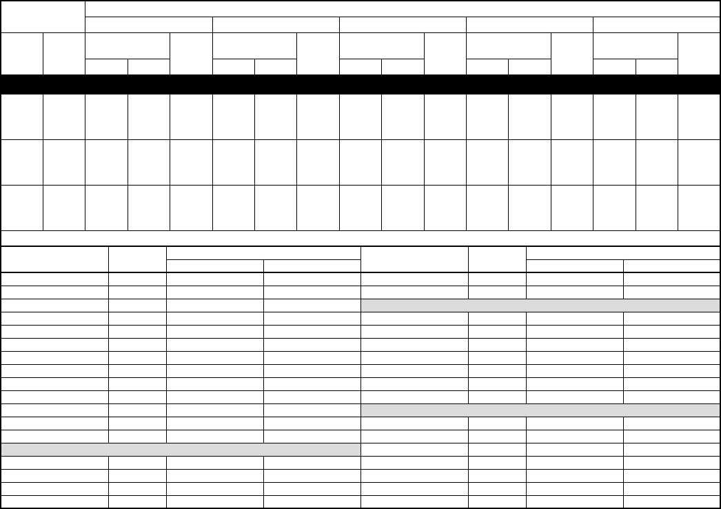
—24—
DETAILED COOLING CAPACITIES* Continued
NOTE: When the required data fall between the published data, interpolation may be performed. Extrapolation is not an acceptable practice.
* Detailed cooling capacities are based on indoor and outdoor unit at same elevation per ARI standard 210/240-94. If additional tubing length and/or indoor
unit is located above outdoor unit, a slight variation in capacity may occur.
†Total and sensible capacities are net capacities. Blower motor heat has been subtracted.
‡Sensible capacities shown are based on 80°F entering air at the indoor coil. For sensible capacities at other than 80°F, deduct 835 Btuh per 1000 CFM of
indoor coil air for each degree below 80°F, or add 835 Btuh per 1000 CFM of indoor coil air per degree above 80°F. When the required data falls between
the published data, interpolation may be performed.
** Unit kW is total of indoor and outdoor unit kilowatts.
EVAPORATOR
AIR
CONDENSER ENTERING AIR TEMPERATURES °F
85 95 105 115 125
CFM EWB
Capacity
MBtuh†Total
System
kW**
Capacity
MBtuh†Total
System
kW**
Capacity
MBtuh†Total
System
kW**
Capacity
MBtuh†Total
System
kW**
Capacity
MBtuh†Total
System
kW**Total Sens‡Total Sens‡Total Sens‡Total Sens‡Total Sens‡
593C060-C Outdoor Section With CC5A/CD5AW060 Indoor Section
1750
72 66.9 33.0 5.85 63.9 31.9 6.39 60.7 30.7 6.97 57.3 29.5 7.61 53.8 28.2 8.29
67 61.1 41.8 5.70 58.3 40.6 6.23 55.4 39.4 6.80 52.3 38.1 7.43 48.9 36.8 8.09
62 55.7 50.3 5.56 53.1 49.0 6.08 50.4 47.6 6.65 47.5 46.0 7.25 44.0 43.8 7.86
57 53.2 53.2 5.50 51.3 51.3 6.03 49.1 49.1 6.61 46.7 46.7 7.22 43.8 43.8 7.86
2000
72 68.1 34.5 5.98 64.9 33.3 6.52 61.6 32.1 7.11 58.1 30.9 7.74 54.4 29.6 8.43
67 62.3 44.2 5.82 59.3 43.0 6.35 56.2 41.8 6.93 53.0 40.5 7.56 49.5 39.2 8.22
62 56.8 53.4 5.69 54.1 52.0 6.21 51.3 50.4 6.78 48.5 48.4 7.39 45.5 45.5 8.04
57 55.2 55.2 5.65 53.1 53.1 6.18 50.8 50.8 6.76 48.4 48.4 7.39 45.4 45.4 8.04
2250
72 69.0 35.8 6.10 65.7 34.7 6.64 62.3 33.4 7.23 58.7 32.2 7.87 55.0 30.9 8.55
67 63.1 46.6 5.95 60.1 45.4 6.48 56.9 44.1 7.05 53.6 42.8 7.68 50.0 41.5 8.35
62 57.7 56.2 5.81 55.0 54.5 6.33 52.3 52.3 6.90 49.7 49.7 7.54 46.8 46.8 8.21
57 56.9 56.9 5.79 54.7 54.7 6.32 52.3 52.3 6.91 49.7 49.7 7.54 46.8 46.8 8.21
Multipliers for Determining the Performance With Other Indoor Sections
Indoor
Section
Unit
Size
Cooling Indoor
Section
Unit
Size
Cooling
Capacity Power Capacity Power
CC5A/CD5AA 060 0.96 0.98 CK5A/CK5BT 060 0.97 0.95
CC5A/CD5AW 060 1.00 1.00 CK5A/CK5BX 060 0.98 0.93
CE3AA 060 1.01 1.00 COILS + 315(A,J)AV066135 VARIABLE-SPEED FURNACE
CK3BA 060 0.96 0.98 CC5A/CD5AA 060 0.96 0.95
CK5A/CK5BA 060 0.96 0.98 CC5A/CD5AW 060 0.97 0.94
CK5A/CK5BN 060 0.96 0.99 CE3AA 060 0.98 0.95
CK5A/CK5BX 060 1.00 1.00 CK3BA 060 0.97 0.95
F(A,B)4(A,B)N(F,B) 060 1.01 1.04 CK5A/CK5BA 060 0.97 0.95
FB4(A,B)NB 070 1.03 1.02 CK5A/CK5BT 060 0.97 0.95
FC4(B,C)N(F,B) 060 1.01 1.04 CK5A/CK5BX 060 0.98 0.93
FC4(B,C)NB 070 1.03 1.02 COILS + 315(A,J)AV066155 VARIABLE-SPEED FURNACE
FG3AAA 060 0.99 0.99 CC5A/CD5AA 060 0.96 0.94
FK4(C,D)NB 006 1.02 0.98 CC5A/CD5AW 060 0.97 0.94
COILS + 315(A,J)AV066110 VARIABLE-SPEED FURNACE CE3AA 060 0.98 0.94
CC5A/CD5AA 060 0.96 0.95 CK3BA 060 0.97 0.95
CE3AA 060 0.98 0.94 CK5A/CK5BA 060 0.97 0.95
CK3BA 060 0.97 0.95 CK5A/CK5BT 060 0.97 0.95
CK5A/CK5BA 060 0.97 0.95 CK5A/CK5BX 060 0.98 0.93

—25—
CONDENSER ONLY RATINGS*
See notes on page 26.
SST
°F
CONDENSER ENTERING AIR TEMPERATURES °F
55 65 75 85 95 105 115
593C018-C, D
TCG 17.9 16.6 15.3 14.0 12.7 11.3 10.0
30 SDT 75.7 84.2 93.0 102.0 111.0 120.0 129.0
KW 1.10 1.18 1.26 1.33 1.39 1.44 1.46
TCG 19.8 18.5 17.1 15.7 14.3 12.9 11.5
35 SDT 77.7 86.2 94.8 104.0 112.0 121.0 130.0
KW 1.13 1.22 1.30 1.38 1.45 1.51 1.55
TCG 21.8 20.5 19.0 17.6 16.1 14.6 13.1
40 SDT 79.9 88.3 96.8 105.0 114.0 123.0 132.0
KW 1.15 1.25 1.34 1.43 1.51 1.58 1.64
TCG 24.0 22.6 21.0 19.5 17.9 16.4 14.8
45 SDT 82.3 90.4 98.9 107.0 116.0 125.0 134.0
KW 1.18 1.28 1.38 1.48 1.57 1.65 1.72
TCG 26.3 24.8 23.2 21.6 19.9 18.2 16.6
50 SDT 84.9 92.8 101.0 110.0 118.0 127.0 135.0
KW 1.20 1.31 1.42 1.53 1.63 1.72 1.80
TCG 28.6 27.1 25.4 23.7 22.0 20.2 18.5
55 SDT 87.6 95.3 103.0 112.0 120.0 129.0 137.0
KW 1.23 1.35 1.46 1.58 1.69 1.79 1.88
593C024-C, D
TCG 24.0 22.3 20.5 18.7 16.9 15.1 13.3
30 SDT 81.3 89.8 98.6 108.0 117.0 126.0 136.0
KW 1.52 1.63 1.73 1.81 1.88 1.93 1.96
TCG 26.6 24.8 22.9 21.0 19.2 17.3 15.4
35 SDT 83.6 91.9 101.0 109.0 118.0 127.0 137.0
KW 1.57 1.68 1.79 1.89 1.97 2.04 2.08
TCG 29.4 27.5 25.5 23.5 21.5 19.5 17.6
40 SDT 86.2 94.3 103.0 111.0 120.0 129.0 138.0
KW 1.61 1.74 1.86 1.97 2.06 2.14 2.20
TCG 32.3 30.3 28.2 26.1 24.0 21.9 19.8
45 SDT 88.9 96.8 105.0 114.0 122.0 131.0 140.0
KW 1.66 1.79 1.92 2.05 2.15 2.25 2.32
TCG 35.3 33.2 31.1 28.8 26.6 24.4 22.2
50 SDT 92.0 99.5 108.0 116.0 124.0 133.0 141.0
KW 1.71 1.85 1.99 2.12 2.25 2.35 2.44
TCG 38.4 36.3 34.1 31.7 29.4 27.0 24.7
55 SDT 95.3 102.0 110.0 118.0 127.0 135.0 144.0
KW 1.76 1.91 2.06 2.20 2.34 2.46 2.56
593C030-C, D
TCG 30.2 27.9 25.6 23.4 21.3 19.3 17.3
30 SDT 81.3 90.5 99.8 109.0 118.0 128.0 137.0
KW 1.88 2.02 2.15 2.27 2.36 2.44 2.50
TCG 33.5 31.0 28.6 26.3 24.0 21.8 19.7
35 SDT 83.4 92.5 102.0 111.0 120.0 129.0 139.0
KW 1.93 2.09 2.24 2.37 2.48 2.57 2.65
TCG 37.1 34.4 31.8 29.3 26.8 24.5 22.2
40 SDT 85.7 94.7 104.0 113.0 122.0 131.0 140.0
KW 1.99 2.16 2.32 2.47 2.59 2.70 2.79
TCG 40.8 38.0 35.2 32.5 29.8 27.3 24.8
45 SDT 88.1 97.0 106.0 115.0 124.0 133.0 142.0
KW 2.04 2.23 2.41 2.57 2.71 2.84 2.94
TCG 44.8 41.7 38.8 35.9 33.0 30.3 27.6
50 SDT 90.7 99.5 108.0 117.0 126.0 135.0 144.0
KW 2.09 2.29 2.49 2.67 2.83 2.97 3.09
TCG 49.0 45.7 42.6 39.5 36.4 33.5 30.6
55 SDT 93.5 102.0 111.0 120.0 129.0 137.0 146.0
KW 2.14 2.36 2.57 2.77 2.94 3.10 3.25
593C036-C, D
30 TCG 35.9 33.4 30.9 28.4 25.9 23.4 21.0
SDT 80.5 89.7 98.9 108.0 118.0 127.0 136.0
KW 2.20 2.38 2.55 2.70 2.82 2.93 3.00
35 TCG 39.7 37.1 34.4 31.7 29.1 26.5 23.9
SDT 82.6 91.6 101.0 110.0 119.0 128.0 138.0
KW 2.25 2.45 2.64 2.80 2.95 3.07 3.17
40 TCG 43.8 41.0 38.1 35.3 32.5 29.7 27.0
SDT 84.8 93.7 103.0 112.0 121.0 130.0 139.0
KW 2.30 2.52 2.72 2.91 3.08 3.22 3.34
45 TCG 48.1 45.1 42.1 39.1 36.1 33.1 30.2
SDT 87.2 96.0 105.0 114.0 123.0 132.0 141.0
KW 2.35 2.59 2.81 3.02 3.20 3.37 3.51
50 TCG 52.6 49.5 46.3 43.1 39.9 36.7 33.6
SDT 89.7 98.4 107.0 116.0 125.0 134.0 143.0
KW 2.40 2.66 2.90 3.12 3.33 3.52 3.68
55 TCG 57.4 54.0 50.7 47.3 43.9 40.5 37.2
SDT 92.4 101.0 110.0 119.0 127.0 136.0 145.0
KW 2.45 2.72 2.98 3.23 3.46 3.66 3.85

—26—
CONDENSER ONLY RATINGS* Continued
* ARI listing applies only to systems shown in Ratings and Performance table.
KW — Total Power (kW)
SDT — Saturated Temperature Leaving Compressor (°F)
SST — Saturated Temperature Entering Compressor (°F)
TCG — Gross Cooling Capacity (1000 Btuh)
SST
°F
CONDENSER ENTERING AIR TEMPERATURES °F
55 65 75 85 95 105 115
593C042-C, D
TCG 40.6 37.9 35.2 32.5 29.7 26.9 24.1
30 SDT 81.5 90.4 99.4 108.0 118.0 127.0 136.0
KW 2.56 2.76 2.94 3.10 3.23 3.33 3.43
TCG 44.8 42.0 39.2 36.3 33.4 30.4 27.5
35 SDT 83.7 92.5 101.0 110.0 119.0 128.0 137.0
KW 2.63 2.85 3.05 3.23 3.38 3.51 3.64
TCG 49.3 46.3 43.3 40.3 37.2 34.1 31.0
40 SDT 86.1 94.8 104.0 112.0 121.0 130.0 139.0
KW 2.69 2.93 3.16 3.36 3.54 3.69 3.84
TCG 54.0 50.9 47.7 44.5 41.2 38.0 34.7
45 SDT 88.7 97.2 106.0 115.0 123.0 132.0 141.0
KW 2.76 3.02 3.26 3.49 3.69 3.87 4.04
TCG 58.9 55.7 52.3 48.9 45.5 42.0 38.6
50 SDT 91.4 99.8 108.0 117.0 126.0 134.0 143.0
KW 2.82 3.10 3.37 3.62 3.85 4.04 4.24
TCG 64.1 60.7 57.1 53.6 49.9 46.3 42.7
55 SDT 94.3 103.0 111.0 120.0 128.0 137.0 145.0
KW 2.89 3.19 3.48 3.75 4.00 4.22 4.44
593C048-C
TCG 44.5 42.6 40.6 38.5 36.4 34.2 31.9
30 SDT 80.0 89.8 99.6 109.0 119.0 129.0 139.0
KW 2.76 3.03 3.34 3.68 4.05 4.45 4.87
TCG 48.7 46.7 44.5 42.3 40.1 37.7 35.2
35 SDT 81.8 91.5 101.0 111.0 121.0 131.0 140.0
KW 2.81 3.09 3.39 3.74 4.12 4.53 4.96
TCG 53.1 50.9 48.7 46.4 43.9 41.4 38.8
40 SDT 83.7 93.3 103.0 113.0 123.0 132.0 142.0
KW 2.86 3.14 3.45 3.80 4.19 4.60 5.05
TCG 57.8 55.5 53.1 50.6 48.0 45.3 42.5
45 SDT 85.8 95.3 105.0 115.0 124.0 134.0 144.0
KW 2.92 3.20 3.52 3.87 4.26 4.68 5.14
TCG 62.7 60.2 57.7 55.0 52.3 49.4 46.5
50 SDT 88.0 97.4 107.0 117.0 126.0 136.0 146.0
KW 2.99 3.27 3.59 3.95 4.34 4.77 5.24
TCG 67.9 65.3 62.5 59.7 56.8 53.7 50.6
55 SDT 90.4 99.8 109.0 119.0 128.0 138.0 147.0
KW 3.06 3.35 3.67 4.03 4.42 4.86 5.33
593C060-C
TCG 55.9 53.4 50.9 48.2 45.4 42.5 39.5
30 SDT 84.5 94.2 104.0 114.0 124.0 134.0 143.0
KW 3.47 3.82 4.22 4.65 5.13 5.64 6.16
TCG 61.1 58.4 55.7 52.8 49.8 46.7 43.5
35 SDT 86.7 96.4 106.0 116.0 126.0 136.0 145.0
KW 3.54 3.90 4.31 4.75 5.23 5.75 6.31
TCG 66.6 63.7 60.8 57.7 54.5 51.2 47.8
40 SDT 89.0 98.7 108.0 118.0 128.0 138.0 147.0
KW 3.63 3.99 4.40 4.85 5.35 5.88 6.45
TCG 72.3 69.3 66.1 62.8 59.5 56.0 52.4
45 SDT 91.4 101.0 111.0 120.0 130.0 140.0 150.0
KW 3.72 4.09 4.50 4.96 5.47 6.01 6.60
TCG 78.3 75.1 71.8 68.3 64.7 60.9 57.1
50 SDT 94.1 104.0 113.0 123.0 132.0 142.0 152.0
KW 3.82 4.20 4.62 5.08 5.59 6.15 6.75
TCG 84.7 81.2 77.6 73.9 70.1 66.1 62.0
55 SDT 96.8 106.0 116.0 125.0 135.0 144.0 154.0
KW 3.93 4.31 4.74 5.21 5.73 6.29 6.91
—27—
SYSTEM DESIGN
1. Intended for outdoor installation with free air inlet and outlet. Outdoor fan external static pressure available is less than 0.01-in. wc.
2. Minimum outdoor operating air temperature without low ambient operation accessory is 55°F (12.8°C).
3. Maximum outdoor operating air temperature is 125°F (51.7°C).
4. For reliable operation, unit should be level in all horizontal planes.
5. Maximum elevation of indoor coil above or below base of outdoor unit is: Indoor coil above = 50 ft indoor coil below = 150 ft. (See items 6 and 7
following.)
6. For interconnecting refrigerant tube lengths of 50 to 175 ft or 20 ft vertical differential, consult Long-Line Application Guideline available from
equipment distributor.
7. Crankcase heater required when interconnecting refrigerant tube length exceeds 50 ft.
8. If any refrigerant tubing is buried, provide a minimum 6-in. vertical rise to the valve connections at the unit. Refrigerant tubing lengths up to 36 in.
may be buried without further consideration. For buried lines longer than 3 ft, consult your local distributor.
9. Use only copper wire for electric connection at unit. Aluminum and clad aluminum are not acceptable for the type of connector provided.
10. Mismatches of indoor coil capacity more than 1 size larger than outdoor unit capacity may result in inadequate indoor comfort.
—28—
SPECIFICATIONS SUBJECT TO CHANGE WITHOUT NOTICE
UNIT MUST BE INSTALLED IN ACCORDANCE
WITH INSTALLATION INSTRUCTIONS
Cancels: PDS 593C.18.6
© 2003 Bryant Heating & Cooling Systems, 7310 W. Morris St., Indpls., IN 46231 PRINTED IN U.S.A. Catalog No. 5259-301 2-03
GUIDE SPECIFICATIONS
GENERAL
System Description
Outdoor-mounted, air-cooled, split-system air conditioner unit
suitable for ground or rooftop installation. Unit consists of a her-
metic compressor, an air-cooled coil, propeller-type condenser
fan, and a control box. Unit will discharge supply air upward as
shown on contract drawings. Unit will be used in a refrigeration
circuit to match up to a packaged fan coil or coil unit.
Quality Assurance
Unit will be rated in accordance with the latest edition of ARI
Standard 240.
Unit will be certified for capacity and efficiency, and listed in the
latest ARI directory.
Unit construction will comply with latest edition of ANSI/
ASHRAE and with NEC.
Unit will be constructed in accordance with UL standards and will
carry the UL label of approval. Unit will have c-UL approval.
Unit cabinet will be capable of withstanding Federal Test Method
Standard No. 141 (Method 6061) 500-hr salt spray test.
Air-Cooled condenser coils will be leak tested at 150 psig and
pressure tested at 300 psig.
Delivery, Storage, and Handling
Unit will be shipped as single package only and is stored and
handled per unit manufacturer’s recommendations.
Warranty (for inclusion by specifying engineer)
U.S. and Canada only.
PRODUCTS
Equipment
Factory assembled, single piece, air-cooled air conditioner unit.
Contained within the unit enclosure will be all factory wiring, pip-
ing, controls, compressor, refrigerant charge (R-22), and special
features required prior to field start-up.
Unit Cabinet
Unit cabinet will be constructed of galvanized steel, bonderized,
and coated with a powder coat paint.
Fans
Condenser fan will be direct-drive propeller type, discharging air
upward.
Air-Cooled, Split-System
Air Conditioner
593C
1-1/2 to 5 Tons Nominal
Condenser fan motors will be totally enclosed, 1-phase type with
class B insulation and permanently lubricated bearings.
Shafts will be corrosion resistant.
Fan blades will be statically and dynamically balanced.
Condenser fan openings will be equipped with steel wire safety
guards.
Compressor
Compressor will be hermetically sealed.
Compressor will be mounted on rubber vibration isolators.
Condenser Coil
Condenser coil will be air cooled.
Coil will be constructed of aluminum fins mechanically bonded to
copper tubes which are then cleaned, dehydrated, and sealed.
Refrigeration Components
Refrigeration circuit components will include liquid-line shutoff
valve with sweat connections, suction tube shutoff valves with
sweat connections, system charge of R-22 (R-410A) refrigerant,
and compressor oil.
Operating Characteristics
The capacity of the unit will meet or exceed Btuh at a
suction temperature of °F. The power consumption at full
load will not exceed kw.
Combination of the unit and the evaporator or fan coil unit will
have a total net cooling capacity of Btuh or greater at con-
ditions of CFM entering air temperature at the evaporator
at °F wet bulb and °F dry bulb, and air entering the
unit at °F.
The system will have an SEER of Btuh/watt or greater at
DOE conditions.
Electrical Requirements
Nominal unit electrical characteristics will be v, 1 single
phase, 60 hz. The unit will be capable of satisfactory operation
within voltage limits of v to v.
Unit electrical power will be single point connection.
Control circuit will be 24v.
Special Features
Refer to section of this literature identifying accessories and de-
scriptions for specific features and available enhancements.
