Bryant Air Conditioner 116B Users Manual PDS116B 04
Bryant Air Conditioner 116B PDS116B-04
116B to the manual 939eda02-f816-4cbd-9659-06afcae64de4
2015-02-02
: Bryant Bryant-Air-Conditioner-116B-Users-Manual-411802 bryant-air-conditioner-116b-users-manual-411802 bryant pdf
Open the PDF directly: View PDF ![]() .
.
Page Count: 22
- FEATURES / BENEFITS
- MODEL NUMBER NOMENCLATURE
- STANDARD FEATURES
- PHYSICAL DATA
- REFRIGERANT PIPING LENGTH LIMITATIONS
- LONG LINE APPLICATIONS
- VAPOR LINE SIZING AND COOLING CAPACITY LOSS
- ACCESSORY THERMOSTATS
- ACCESSORIES
- ACCESSORY USAGE GUIDELINE
- ELECTRICAL DATA
- A--WEIGHTED SOUND POWER LEVEL (dBA)
- A--WEIGHTED SOUND POWER LEVEL (dBA) WITH SOUND SHIELD
- CHARGING SUBCOOLING
- DIMENSIONS -- ENGLISH
- DIMENSIONS -- SI
- CLEARANCES
- TESTED AHRI COMBINATION RATINGS
- DETAILED COOLING CAPACITIES
- CONDENSER ONLY RATINGS
- GUIDE SPECIFICATIONS
- SYSTEM DESIGN SUMMARY

116B
LegacytLine 16 Air Conditioner
with PuronrRefrigerant
1--1/2 to 5 Nominal Tons
Product Data
the environmentally sound refrigerant
Bryant’s Air Conditioners with Puronrrefrigerant provide a
collection of features unmatched by any other family of
equipment. The 116B has been designed utilizing Bryant’s Puron
refrigerant. The environmentally sound refrigerant allows you to
make a responsible decision in the protection of the earth’s ozone
layer.
This product has been designed and manufactured to meet
Energy Starrcriteria for energy efficiency when matched with
appropriate coil components. Refer to the combination ratings in
the Product Data for system combinations that meet Energy Starr
guidelines.
NOTE:Ratings contained in this document are subject to
change at any time. Always refer to the AHRI directory
(www.ahridirectory.org) for the most up--to--date ratings
information.
INDUSTRY LEADING
FEATURES / BENEFITS
Efficiency
S14 -- 16.5 SEER/11.0-- 13.5 EER
SMicrotube Technologytrefrigeration system
SIndoor air quality accessories available
Sound
SSound level as low as 76 dBA
SSound level as low as 74 dBA with accessory sound
blanket
Comfort
SSystem supports EdgerThermidistattor standard
thermostat controls
Reliability
SPuronrrefrigerant -- environmentally sound, won’t
deplete the ozone layer and low lifetime servce cost.
SScroll compressor
SInternal pressure relief valve
SInternal thermal overload
SFilter drier
SBalanced refrigeration system for maximum reliability
Durability
DuraGuardtprotection package:
SSolid, durable sheet metal construction
SDense wire coil guard standard
SBaked--on, complete outer coverage, powder paint
Applications
SLong--line -- up to 250 feet (76.20 m) total equivalent
length, up to 200 feet (60.96 m) condenser above
evaporator, or up to 80 ft. (24.38 m) evaporator above
condenser (See Longline Guide for more information.)
SLow ambient (down to --20_F/--28.9_C)) with
accessory kit
2
MODEL NUMBER NOMENCLATURE
12345678910111214
N N N A A/N N N N N A/N A/N N A
116BNA03600 00
Prod-
uct
Family
Tier SEER Major
Series Voltage Grille
Variations
Cooling Capacity Open Open Open Series
1=AC
1=
Legacy
RNC
6=16 SEER B=Puron
N=
208---230--- 1
or
208/230--- 1
A=Dense 0=Not
Defined
0=Not
Defined
0=Not
Defined
the environmentally sound refrigerant
REGISTERED
ISO 9001:2000
This product has been designed and manufactured to
meet Energy Star®criteria for energy efficiency when
matched with appropriate coil components. However,
proper refrigerant charge and proper air flow are critical
to achieve rated capacity and efficiency. Installation of
this product should follow all manufacturing refrigerant
charging and air flow instructions. Failure to confirm
proper charge and air flow may reduce energy
efficiency and shorten equipment life.
Use of the AHRI Certified
TM Mark indicates a
manufacturer’s
participation in the
program For verification
of certification for individual
products, go to
www.ahridirectory.org.
STANDARD FEATURES
Feature 018 024 030 036 042 048 / 049 060 / 061
Puron Refrigerant XXXXXXX
Maximum SEER * 16.0 16.0 16.5 16.5 16.0 16.0 16.0
Scroll Compressor XXXXXXX
FieldInstalledFilterDrier XXXXXXX
Front Seating Service Valves XXXXXXX
Internal Pressure Relief Valve XXXXXXX
Internal Thermal Overload XXXXXXX
Long Line capability XXXXXXX
Low Ambient capability with Kit XXXXXXX
Dense Grille XXXXXXX
* With approved combinations
X=Standard
PHYSICAL DATA
UNIT SIZE --- VOLTAGE, SERIES 018 --- B 024 --- A 030 --- A 036 --- A 042--- A 048 --- B 049 --- A 060 --- A 061 --- A
Operating Weight lb (kg) 125
(56.7)
147
(66.5)
153
(69.3)
165
(74.8)
213
(96.4)
264
(119.7)
231
(104.8)
272
(123.4)
272
(123.4)
Shipping Weight lb (kg) 154
(69.9)
183
(82.8)
188
(85.2)
204
(92.5)
254
(115.2)
317
(143.8)
269
(222.0)
310
(140.6)
310
(140.6)
Compressor Type Scroll
REFRIGERANT Puron®(R---410A)
Control TXV (Puron®Hard Shutoff)
Charge lb (kg) 4.60
(2.09)
6.00
(2.72)
6.81
(3.09)
7.00
(3.18)
8.62
(3.91)
13.0
(5.90)
9.00
(4.08)
14.50
(6.58)
14.50
(6.58)
COND FAN Propeller Type, Direct Drive
Air Discharge Vertical Vertical
Air Qty (CFM) 1881 2614 2614 3223 3810 4046 4046 4046 4046
Motor HP 1/12 1/10 1/10 1/12 1/5 1/4 1/4 1/4 1/4
Motor RPM 1100 1100 1100 800 800 800 800 800 800
COND COIL
Face Area (Sq ft) 11.50 15.10 17.20 17.60 25.15 25.15 25.15 30.15 30.15
Fins per In. 25 25 25 25 25 20 20 20 20
Rows 1 1 1 1 1 2 1 2 2
Circuits 3 4 4 4 6 7 7 8 8
VALVECONNECT.(In.ID)
Vapor 3/4 3/4 3/4 7/8 7/8 7/8 7/8 7/8 7/8
Liquid 3/8 3/8 3/8 3/8 3/8 3/8 3/8 3/8 3/8
REFRIGERANT TUBES (In. OD)
Rated Vapor* 3/4 7/8 1 --- 1 / 8
Max Liquid Line {3/8
* Units are rated with 25 ft (7.6 m) of lineset length. See Vapor Line Sizing and Cooling Capacity Loss table when using other sizes and lengths of lineset.
Note: See unit Installation Instruction for proper installation.
{See Liquid Line Sizing For Cooling Only Systems with Puron Refrigerant tables.
116B
3
REFRIGERANT PIPING LENGTH LIMITATIONS
Liquid Line Sizing and Maximum Total Equivalent Lengths{for Cooling Only Systems with PuronrRefrigerant:
The maximum allowable length of a residential split system depends on the liquid line diameter and vertical separation between indoor and
outdoor units.
See Table below for liquid line sizing and maximum lengths :
Maximum Total Equivalent Length
Outdoor Unit BELOW Indoor Unit
Size Liquid Line
Connection
Liquid
Line
Diam.
w/ TXV
AC with Puron Refrigerant Maximum Total Equivalent Length{: Outdoor unit BELOW Indoor
Vertical Separation ft (m)
0 --- 5
(0---1.5)
6 --- 1 0
(1.8---3.0)
11---20
(3.4---6.1)
21---30
(6.4---9.1)
31---40
(9.4---12.2)
41---50
(12.5---15.2)
51---60
(15.5---18.3)
61---70
(18.6---21.3)
71---80
(21.6---24.4)
18000
AC with
Puron
3/8
1/4 150 150 125 100 100 75 --- --- --- --- --- ---
5/16 250* 250* 250* 250* 250* 250* 250* 225* 150
3/8 250* 250* 250* 250* 250* 250* 250* 250* 250*
24000
AC with
Puron
3/8
1/4 75 75 75 50 50 --- --- --- --- --- --- --- ---
5/16 250* 250* 250* 250* 250* 225* 175 125 100
3/8 250* 250* 250* 250* 250* 250* 250* 250* 250*
30000
AC with
Puron
3/8
1/4 30 --- --- --- --- --- --- --- --- --- --- --- --- --- --- --- ---
5/16 175 225* 200 175 125 100 75 --- --- --- ---
3/8 250* 250* 250* 250* 250* 250* 250* 250* 250*
36000
AC with
Puron
3/8 5/16 175 150 150 100 100 100 75 --- --- --- ---
3//8 250* 250* 250* 250* 250* 250* 250* 250* 250*
42000
AC with
Puron
3/8 5/16 125 100 100 75 75 50 --- --- --- --- --- ---
3/8 250* 250* 250* 250* 250* 250* 250* 250* 150
48000
AC with
Puron
3/8 3/8 250* 250* 250* 250* 250* 250* 230 160 --- ---
49000
AC with
Puron
3/8 3/8 250* 250* 250* 250* 250* 250* 230 160 --- ---
60000
AC with
Puron
3/8 3/8 250* 250* 250* 225* 190 150 110 --- --- --- ---
61000
AC with
Puron
3/8 3/8 250* 250* 250* 225* 190 150 110 --- --- --- ---
* Maximum actual length not to exceed 200 ft (61 m)
{Total equivalent length accounts for losses due to elbows or fitting. See the Long Line Guideline for details.
--- --- = o u t s i d e a c c e p t a b l e r a n g e
Maximum Total Equivalent Length
Outdoor Unit ABOVE Indoor Unit
Size Liquid Line
Connection
Liquid
Line
Diam.
w/ TXV
AC with Puron Refrigerant Maximum Total Equivalent Length{: Outdoor unit ABOVE Indoor
Vertical Separation ft (m)
25
(7.6)
26---50
(7.9---15.2)
51---75
(15.5---22.9)
76---100
(23.2---30.5)
101---125
(30.8---38.1)
126---150
(38.4---45.7)
151---175
(46.0---53.3)
176---200
(53.6---61.0)
18000
AC with
Puron
3/8
1/4 175 250* 250* 250* 250* 250* 250* 250*
5/16 250* 250* 250* 250* 250* 250* 250* 250*
3/8 250* 250* 250* 250* 250* 250* 250* 250*
24000
AC with
Puron
3/8
1/4 100 125 175 200 225* 250* 250* 250*
5/16 250* 250* 250* 250* 250* 250* 250* 250*
3/8 250* 250* 250* 250* 250* 250* 250* 250*
30000
AC with
Puron
3/8
1/4 30 --- --- --- --- --- --- --- --- --- --- --- --- --- ---
5/16 250* 250* 250* 250* 250* 250* 250* 250*
3/8 250* 250* 250* 250* 250* 250* 250* 250*
36000
AC with
Puron
3/8 5/16 225* 250* 250* 250* 250* 250* 250* 250*
3/8 250* 250* 250* 250* 250* 250* 250* 250*
42000
AC with
Puron
3/8
5/16 175 200 250* 250* 250* 250* 250* 250*
3/8 250* 250* 250* 250* 250* 250* 250* 250*
48000
AC with
Puron
3/8 3/8 250* 250* 250* 250* 250* 250* 250* 250*
49000
AC with
Puron
3/8 3/8 250* 250* 250* 250* 250* 250* 250* 250*
60000
AC with
Puron
3/8 3/8 250* 250* 250* 250* 250* 250* 250* 250*
61000
AC with
Puron
3/8 3/8 250* 250* 250* 250* 250* 250* 250* 250*
* Maximum actual length not to exceed 200 ft (61 m)
{Total equivalent length accounts for losses due to elbows or fitting. See the Long Line Guideline for details.
--- --- = o u t s i d e a c c e p t a b l e r a n g e
116B
4
REFRIGERANT CHARGE ADJUSTMENTS
Liquid Line Size Puron Charge oz/ft
3/8 0.60
(Factory charge for lineset = 9 oz)
5/16 0.40
1/4 0.27
Units are factory charged for 15 ft (4.6 m) of 3/8” liquid line. The factory charge for 3/8” lineset 9 oz. When using other length or diameter
liquid lines, charge adjustments are required per the chart above.
Charging Formula:
[(Lineset oz/ft x total length) – (factory charge for lineset)] = charge adjustment
Example 1: System has 15 ft of line set using existing 1/4“ liquid line. What charge adjustment is required?
Formula: (.27 oz/ft x 15ft) – (9 oz) = (-4.95) oz.
Net result is to remove 4.95 oz of refrigerant from the system
Example 2: System has 45 ft of existing 5/16” liquid line. What is the charge adjustment?
Formula: (.40 oz/ft. x 45ft) – (9 oz.) = 9 oz.
Net result is to add 9 oz of refrigerant to the system
LONG LINE APPLICATIONS
An application is considered Long Line, when the refrigerant level in the system requires the use of accessories to maintain acceptable
refrigerant management for systems reliability. See Accessory Usage Guideline table for required accessories. Defining a system as long line
depends on the liquid line diameter, actual length of the tubing, and vertical separation between the indoor and outdoor units.
For Air Conditioner systems, the chart below shows when an application is considered Long Line.
AC WITH PURONrREFRIGERANT LONG LINE DESCRIPTION ft (m)
Beyond these lengths, long line accessories are required
Liquid Line Size Units On Same Level Outdoor Below Indoor Outdoor Above Indoor
1/4 No accessories needed within allowed
lengths
No accessories needed within allowed
lengths 175 (53.3)
5/16 120 (36.6) 50 (15.2) 120 (36.6)
3/8 80 (24.4) 35 (10.7) 80 (24.4)
Note: SeeLongLineGuidelinefordetails
VAPOR LINE SIZING AND COOLING CAPACITY LOSS
Acceptable vapor line diameters provide adequate oil return to the compressor while avoiding excessive capacity loss. The suction line
diameters shown in the chart below are acceptable for AC systems with Puron refrigerant:
Unit
Nominal
Size (Btuh)
Maximum
Liquid Line
Diameters
(In. OD)
Vapor Line
Diameters
(In. OD)
Cooling Capacity Loss (%)
Total Equivalent Line Length ft. (m)
26 --- 50
(7.9---15.2)
51 --- 80
(15.5---24.4)
81 --- 100
(24.7---30.5)
101 --- 125
(30.8---38.1)
126 --- 150
(38.4---45.7)
151 --- 175
(46.0---53.3)
176 --- 200
(53.6---61.0)
201 --- 225
(61.3---68.6)
226 --- 250
(68.9---76.2)
18000
1Stage
AC with
Puron
3/8
1/2 1 2 3 5 6 7 8 9 11
5/8 0 1 1 1 2 2 2 3 3
3/4 0 0 0 0 1 1 1 1 1
24000
1Stage
AC with
Puron
3/8
5/8 0 1 2 2 3 3 4 5 5
3/4 0 0 1 1 1 1 1 2 2
7/8 0 0 0 0 0 1 1 1 1
30000
1Stage
AC with
Puron
3/8
5/8 1 2 3 3 4 5 6 7 8
3/4 0 0 1 1 1 2 2 2 3
7/8 0 0 0 0 1 1 1 1 1
36000
1Stage
AC with
Puron
3/8
5/8 1 2 4 5 6 8 9 10 12
3/4 0 1 1 2 2 3 3 4 4
7/8 0 0 0 1 1 1 1 2 2
42000
1Stage
AC with
Puron
3/8
3/4 0 1 2 2 3 4 4 5 6
7/8 0 0 1 1 1 2 2 2 3
11/8 0 0 0 0 0 0 0 0 0
48000,
49000
1Stage
AC with
Puron
3/8
3/4 0 1 2 3 4 5 5 6 7
7/8 0 0 1 1 2 2 2 3 3
11/8 0 0 0 0 0 0 0 1 1
60000,
61000
1Stage
AC with
Puron
3/8
3/4 1 2 4 5 6 7 9 10 11
7/8 0 1 2 2 3 4 4 5 5
11/8 0 0 0 1 1 1 1 1 1
Applications in this area may be long line and may have height restrictions. See the Residential Piping and Long Line Guideline.
116B
5
ACCESSORY THERMOSTATS
PART NUMBER PROGRAM GAS ELECTRIC HEAT COOL
T 2 --- PA C 0 1 5 --- 2 D a y √ √ 1 1
T 2 --- N A C 0 1 NP √ √ 1 1
T2SNAC01 NP √ √ 1 1
THERMOSTAT ACCESSORIES
PART NUMBER BRIEF DESCRIPTION THERMOSTATS USED WITH
TSTATXXCNV10 Thermostat Conversion Kit (4 to 5 wire) --- 10
pack All Bryantrbranded thermostats
T X --- L B P 0 1 LargeDecorativeBackplate T 6 --- P x x , T 6 --- N x x , a n d T 2 --- P x x
T X --- M B P 0 1 Medium Decorative Backplate T 2 --- N x x a n d T 1 --- P x x
ACCESSORIES
KIT NUMBER DESCRIPTION Unit Sizes --- Series
018 --- B 024 --- A 030 --- A 036 --- A 042 --- A 048 --- B 049 --- A 060 --- A 061 --- A
KAAFT0101AAA FREEZE THERMOSTAT X X X X X X X X X
KAATD0101TDR TIME DELAY RELAY X X X X X X X X X
KSALA0301410 LOW AMBIENT PSW X X X X X X X X X
KSALA0601AAA{MOTORMASTER 230V X X X X X X X X X
HC32GE234 MOTOR FAN BALL BEARING X
HC34GE240 MOTOR FAN BALL BEARING X X
HC32GE229 MOTOR FAN BALL BEARING X
HC38GE228 MOTOR FAN BALL BEARING X
HC40GE228 MOTOR FAN BALL BEARING X X X X
KSAHS1701AAA HARD START (CAP / RELAY) X X X X X X X X X
KSACY0101AAA CYCLE PROTECTOR X X X X X X X X X
KSASF0101AAA SUPPORT FEET X X X X X X X X X
KAACS0201PTC START ASSIST PTC X X X X X X X X X
KAALS0201LLS LIQUID LINE SOLENOID X X X X X X X X X
KAAWS0101AAA WINTER START X X X X X X X X X
KAACH1701AAA CRANKCASE HTR X X X X
KAACH1601AAA CRANKCASE HTR X S S S S
KSATX0201PUR TXV PURON HSO X X X
KSATX0301PUR TXV PURON HSO X
KSATX0401PUR TXV PURON HSO X X
KSATX0501PUR TXV PURON HSO X X X
KSASH0601COP SOUND HOOD X X X X X
KSASH2101COP SOUND HOOD X X X X
KAALP0401PUR LOW PRESSURE SWITCH X X X X X X X X X
KAAHI0501PUR HIGH PRESSURE SWITCH X X X X X X X X X
{Required accessories include ball bearing fan motor, compressor start assist (CAP / Relay), crankcase heater, evaporator freeze stat, hard shut---off TXV.
X = Accessory / S --- Standard
116B
6
ACCESSORY USAGE GUIDELINE
ACCESSORY
REQUIRED FOR LOW---AMBI-
ENT COOLING APPLICATIONS
(Below 55°F/12.8_C)
REQUIRED FOR LONG
LINE
APPLICATIONS*
(Over 80 ft./24.38 m)
REQUIRED FOR
SEA COAST
APPLICATIONS
(Within2miles/3.22km)
Ball Bearing Fan Motor Yes{No No
Compressor Start Assist Capacitor and Relay Yes Yes No
Crankcase Heater Yes Yes No
Evaporator Freeze Thermostat Yes No No
H a r d S h u t --- O f f T X V Yes Yes Yes
Liquid Line Solenoid Valve No No No
Motor Master®Control or
L o w --- a m b i e n t P r e s s u r e S w i t c h Yes No No
Support Feet Recommended No Recommended
Winter Start Control Yes No No
* For tubing line sets between 80 and 200 ft. (24.38 and 60.96 m) and/or 20 ft. (6.09 m) vertical differential, refer to Residential Split---System Longline
Application Guideline.
{Required for Low ---Ambient Controller (full modulation feature) MotorMasterrControl.
Accessory Description and Usage (Listed Alphabetically)
1. Ball--Bearing Fan Motor
A fan motor with ball bearings which permits speed reduction
while maintaining bearing lubrication.
Usage Guideline:
Required on all units when MotorMasterris used.
2. Compressor Start Assist -- Capacitor and Relay
Start capacitor and relay gives a ”hard” boost to compressor
motor at each start up.
Usage Guideline:
Required for reciprocating compressors in the
following applications:
Long line
Low ambient cooling
Hard shut off expansion valve on indoor coil
Liquid line solenoid on indoor coil
Required for single--phase scroll compressors in the
following applications:
Long line
Low ambient cooling
Suggested for all compressors in areas with a history of
low voltage problems.
3. Compressor Start Assist — PTC Type
Solid state electrical device which gives a ”soft” boost to the
compressor at each start--up.
Usage Guideline:
Suggested in installations with marginal power supply.
4. Crankcase Heater
An electric resistance heater which mounts to the base of the
compressor to keep the lubricant warm during off cycles.
Improves compressor lubrication on restart and minimizes the
chance of liquid slugging.
Usage Guideline:
Required in low ambient cooling applications.
Required in long line applications.
Suggested in all commercial applications.
5. Cycle Protector
The cycle protector is designed to prevent compressor short
cycling. This control provides an approximate 5--minute delay
after power to the compressor has been interrupted for any
reason, including power outage, protector control trip, thermostat
jiggling, or normal cycling.
6. Evaporator Freeze Thermostat
An SPST temperature--actuated switch that stops unit operation
when evaporator reaches freeze--up conditions.
Usage Guideline:
Required when low ambient kit has been added.
7. Low--Ambient Pressure Switch Kit
A long life pressure switch which is mounted to outdoor unit
service valve. It is designed to cycle the outdoor fan motor in
order to maintain head pressure within normal operating limits
(approximately 100 psig to 225 psig). The control will maintain
working head pressure at low--ambient temperatures down to 0_F
(--18_C) when properly installed.
Usage Guideline:
A Low--Ambient Pressure Switch or MotorMasterr
Low--Ambient Controller must be used when cooling operation is
used at outdoor temperatures below 55_F (12.8_C).
8. MotorMasterrLow--Ambient Controller
A fan--speed control device activated by a temperature sensor,
designed to control condenser fan motor speed in response to the
saturated, condensing temperature during operation in cooling
mode only. For outdoor temperatures down to --20_F (--28.9_C),
it maintains condensing temperature at 100_F±10_F (37.8_C±
5.5_C).
Usage Guideline:
A MotorMasterrLow Ambient Controller or
Low--Ambient Pressure Switch must be used when
cooling operation is used at outdoor temperatures
below 55_F (12.8_C).
Suggested for all commercial applications.
9. Outdoor Air Temperature Sensor
Designed for use with Bryant Thermostats listed in this
publication. This device enables the thermostat to display the
outdoor temperature. This device also
is required to enable special thermostat features such as auxiliary
heat lock out.
Usage Guideline:
Suggested for all Bryant thermostats listed in this
publication.
116B

7
Accessory Description and Usage (Listed Alphabetically) (Continued)
10. Sound Hood
Wraparound sound reducing cover for the compressor. Reduces
the sound level by about 2 dBA.
Usage Guideline:
Suggested when unit is installed closer than 15 ft (4.57 m) to
quiet areas, bedrooms, etc.
Suggested when unit is installed between two houses less
than 10 ft (3.05 m) apart.
11. Support Feet
Four stick--on plastic feet that raise the unit 4 in. (101.6 mm)
above the mounting pad. This allows sand, dirt, and other debris
to be flushed from the unit base, minimizing corrosion.
Usage Guideline:
Suggested in the following applications:
Coastal installations.
Windy areas or where debris is normally circulating.
Rooftop installations.
For improved sound ratings.
12. Thermostatic Expansion Valve (TXV)
A modulating flow--control valve which meters refrigerant liquid
flow rate into the evaporator in response to the superheat of the
refrigerant gas leaving the evaporator.
Kit includes valve, adapter tubes, and external equalizer tube.
Hard shut off types are available.
NOTE: When using a hard shut off TXV with single phase
reciprocating compressors, a Compressor Start Assist Capacitor
and Relay is required.
Usage Guideline:
Required to achieve AHRI ratings in certain equipment
combinations. Refer to combination ratings.
Hard shut off TXV or LLS required in air conditioner
long line applications.
Required for use on all zoning systems.
13. Time--Delay Relay
An SPST delay relay which briefly continues operation of indoor
blower motor to provide additional cooling after the compressor
cycles off.
NOTE: Most indoor unit controls include this feature. For those
that do not, use the guideline below.
Usage Guideline:
For improved efficiency ratings for certain
combinations of indoor and outdoor units. Refer to
AHRI Unitary Directory.
14. Winter Start Control
This control is designed to alleviate nuisance opening of the
low--pressure switch by bypassing it for the first 3 minutes of
operation.
116B
8
ELECTRICAL DATA
UNIT SIZE V/PH
OPER VOLTS* COMPR FAN
MCA
MIN WIRE
SIZE{
60°C
MIN WIRE
SIZE{
75°C
MAX
LENGTH
ft. (m)}
60°C
MAX
LENGTH
ft. (m)}
75°C
MAX FUSE**
or CKT BRK
AMPS
MAX MIN LRA RLA FLA
018 --- B
208/230/1---60 253 197
48.0 9.0 0.50 11.8 14 14 67 (20.4) 64 (19.5) 20
024 --- A 58.3 13.5 0.75 17.7 14 14 46 (14.0) 43 (13..1) 25
030 --- A 64.0 12.8 0.75 16.8 14 14 44 (13.4) 41 (12.5) 25
036 --- A 77.0 14.1 0.50 18.1 12 12 57 (17.4) 54 (16.5) 30
042 --- A 112.0 17.9 1.20 23.6 10 10 85 (25.9) 81 (24.7) 40
048 --- B 109.0 19.9 1.20 26.1 10 10 70 (21.3) 67 (20.4) 40
049 --- A 117.0 21.8 1.20 26.1 10 10 70 (21.3) 67 (20.4) 40
060 --- A 135.0 21.4 1.20 28.0 810 91 (27.7) 56 (17.1) 40
061 --- A 134.0 25.0 1.20 32.5 810 94 (28.7) 58 (17.7) 50
* Permissible limits of the voltage range at which the unit will operate satisfactorily
{If wire is applied at ambient greater than 30_C, consult table 310---16 of the NEC (NFPA 70). The ampacity of non ---metallic---sheathed cable (NM), trade
name ROMEX, shall be that of 60_C conditions, per the NEC (NFPA 70) Article 334---80. If other than uncoated (no ---plated), 60 or 75_C insulation, copper
wire (solid wire for 10 AWG or smaller, stranded wire for larger than 10 AWG) is used, consult applicable tables of the NEC (NFPA 70).
}Length shown is as measured one way along wire path between unit and service panel for voltage drop not to exceed 2%.
* * T i m e --- D e l a y f u s e .
FLA --- F u l l L o a d A m p s
LRA --- L o c k e d R o t o r A m p s
MCA --- Minimum Circuit Amps
RLA ---RatedLoadAmps
NOTE: Control circuit is 24---V on all units and requires external power source. Copper wire must be used from service disconnect to unit.
All motors/compressors contain internal overload protection.
Complies with 2007 requirements of ASHRAE Standards 90.1
A--WEIGHTED SOUND POWER LEVEL (dBA)
U n i t S i z e ---
Voltage, Series
Standard
Rating (dBA)
TYPICAL OCTAVE BAND SPECTRUM (dBA without tone adjustment)
125 250 500 1000 2000 4000 8000
0018 --- B 76 52.5 59.0 65.5 70.5 64.5 59.0 54.5
0024 --- A 76 57.5 64.0 69.0 71.0 69.0 64.5 60.0
0030 --- A 76 55.0 63.5 68.0 69.5 67.0 63.5 58.5
0036 --- A 76 50.5 59.5 64.5 70.5 62.0 59.5 54.5
0042 --- A 78 52.5 62.0 66.0 73.5 68.0 62.0 55.5
0048 --- B 78 57.5 61.5 66.0 70.5 65.5 59.5 53.5
0049 --- A 78 51.5 62.0 67.5 73.5 69.0 64.5 62.0
0060 --- A 78 55.0 62.5 67.5 70.5 65.0 61.0 53.5
0061 --- A 78 56.5 63.0 65.5 69.0 67.0 61.5 56.0
NOTE: Tested in accordance with AHRI Standard 270 ---08 (not listed in AHRI).
A--WEIGHTED SOUND POWER LEVEL (dBA) WITH SOUND SHIELD
U n i t S i z e ---
Voltage, Series
Standard
Rating (dBA)
TYPICAL OCTAVE BAND SPECTRUM (dBA without tone adjustment)
125 250 500 1000 2000 4000 8000
0018 --- B 74 55.5 59.0 65.0 68.5 63.5 58.0 52.0
0024 --- A 75 58.0 64.0 69.0 70.5 68.5 64.5 59.5
0030 --- A 75 55.5 63.0 68.0 69.0 67.0 63.0 58.5
0036 --- A 74 51.5 58.5 62.0 65.0 61.0 58.0 52.0
0042 --- A 76 53.0 62.0 65.5 72.0 65.0 61.0 54.0
0048 --- B 76 58.5 61.5 66.0 69.0 64.0 58.5 51.0
0049 --- A 76 53.0 61.5 67.5 72.0 68.0 61.5 59.0
0060 --- A 75 56.5 62.5 66.5 68.0 63.0 59.5 51.5
0061 --- A 75 57.0 63.0 65.5 67.0 65.5 59.0 52.5
NOTE: Tested in accordance with AHRI Standard 270 ---08 (not listed in AHRI).
CHARGING SUBCOOLING (TXV--TYPE EXPANSION DEVICE)
UNIT SIZE --- VOLTAGE, SERIES REQUIRED SUBCOOLING _F(_C)
018 --- B 10 (5.6)
024 --- A 10 (5.6)
030 --- A 10 (5.6)
036 --- A 10 (5.6)
042 --- A 9 (5.0)
048 --- B 10 (5.6)
049 --- A 8 (4.4)
060 --- A 9 (5.0)
061 --- A 9 (5.0)
116B
9
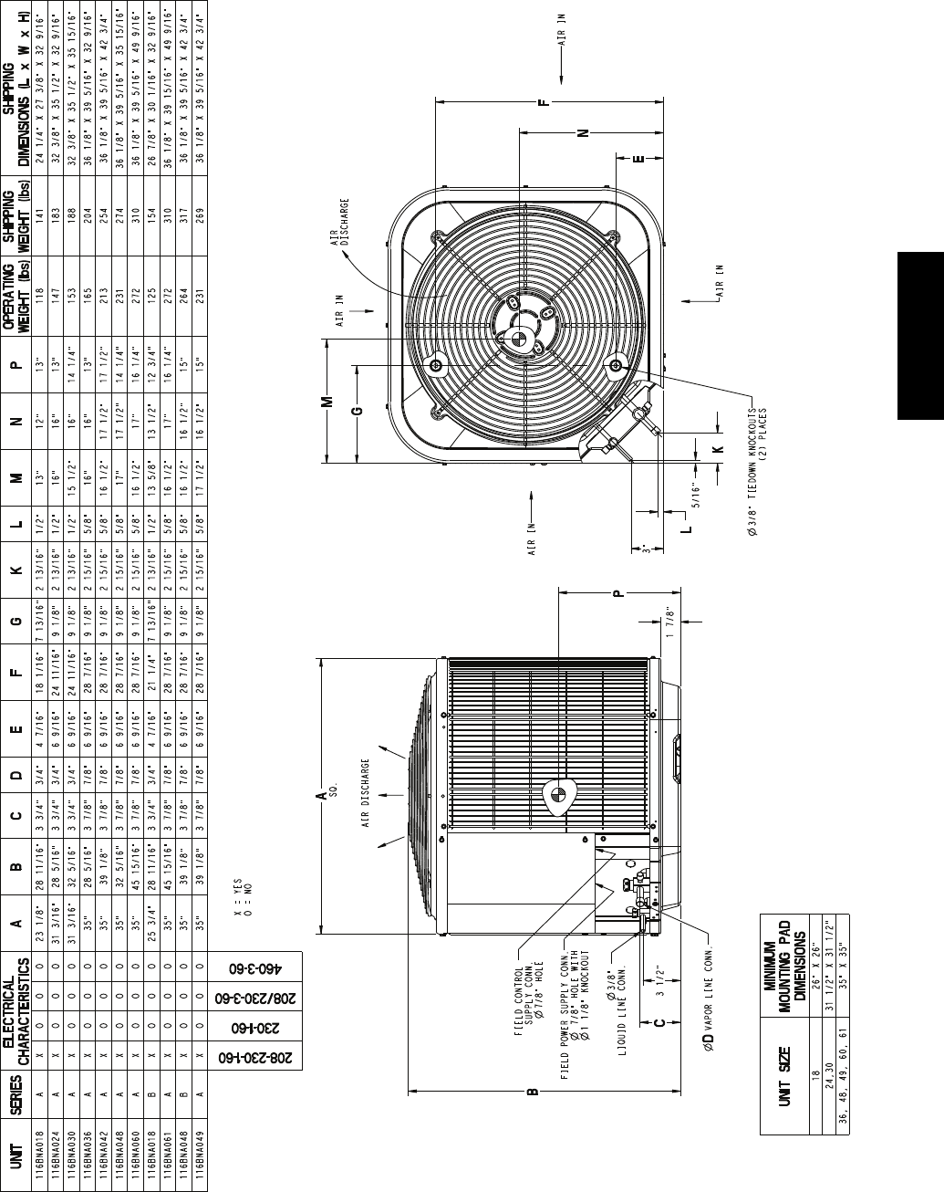
DIMENSIONS -- ENGLISH
B
3"
K
5/16"
L
C
3 1/2"
1 7/8"
N
P
M
E
F
G
A
208-230-1-60
230-1-60
208/230-3-60
460-3-60
UNIT SERIES ELECTRICAL
CHARACTERISTICS ABCDEFGKLMNP
OPERATING
WEIGHT (lbs)
SHIPPING
WEIGHT (lbs)
SHIPPING
DIMENSIONS (L x W x H)
116BNA018 A X O O O 23 1/8" 28 11/16" 3 3/4" 3/4" 4 7/16" 18 1/16" 7 13/16" 2 13/16" 1/2" 13" 12" 13" 118 141 24 1/4" X 27 3/8" X 32 9/16"
116BNA024 A X O O O 31 3/16" 28 5/16" 3 3/4" 3/4" 6 9/16" 24 11/16" 9 1/8" 2 13/16" 1/2" 16" 16" 13" 147 183 32 3/8" X 35 1/2" X 32 9/16"
116BNA030 A X O O O 31 3/16" 32 5/16" 3 3/4" 3/4" 6 9/16" 24 11/16" 9 1/8" 2 13/16" 1/2" 15 1/2" 16" 14 1/4" 153 188 32 3/8" X 35 1/2" X 35 15/16"
116BNA036 A X O O O 35" 28 5/16" 3 7/8" 7/8" 6 9/16" 28 7/16" 9 1/8" 2 15/16" 5/8" 16" 16" 13" 165 204 36 1/8" X 39 5/16" X 32 9/16"
116BNA042 A X O O O 35" 39 1/8" 3 7/8" 7/8" 6 9/16" 28 7/16" 9 1/8" 2 15/16" 5/8" 16 1/2" 17 1/2" 17 1/2" 213 254 36 1/8" X 39 5/16" X 42 3/4"
116BNA048 A X O O O 35" 32 5/16" 3 7/8" 7/8" 6 9/16" 28 7/16" 9 1/8" 2 15/16" 5/8" 17" 17 1/2" 14 1/4" 231 274 36 1/8" X 39 5/16" X 35 15/16"
116BNA060 A X O O O 35" 45 15/16" 3 7/8" 7/8" 6 9/16" 28 7/16" 9 1/8" 2 15/16" 5/8" 16 1/2" 17" 16 1/4" 272 310 36 1/8" X 39 5/16" X 49 9/16"
116BNA018 B X O O O 25 3/4" 28 11/16" 3 3/4" 3/4" 4 7/16" 21 1/4" 7 13/16" 2 13/16" 1/2" 13 5/8" 13 1/2" 12 3/4" 125 154 26 7/8" X 30 1/16" X 32 9/16"
116BNA061 A X O O O 35" 45 15/16" 3 7/8" 7/8" 6 9/16" 28 7/16" 9 1/8" 2 15/16" 5/8" 16 1/2" 17" 16 1/4" 272 310 36 1/8" X 39 15/16" X 49 9/16"
116BNA048 B X O O O 35" 39 1/8" 3 7/8" 7/8" 6 9/16" 28 7/16" 9 1/8" 2 15/16" 5/8" 16 1/2" 16 1/2" 15" 264 317 36 1/8" X 39 5/16" X 42 3/4"
116BNA049 A X O O O 35" 39 1/8" 3 7/8" 7/8" 6 9/16" 28 7/16" 9 1/8" 2 15/16" 5/8" 17 1/2" 16 1/2" 15" 231 269 36 1/8" X 39 5/16" X 42 3/4"
UNIT SIZE
MINIMUM
MOUNTING PAD
DIMENSIONS
18 26" X 26"
24,30 31 1/2" X 31 1/2"
36, 48, 49, 60, 61 35" X 35"
AIR
DISCHARGE
AIR DISCHARGE
SQ.
AIR IN
VAPOR LINE CONN.
D
3/8"
LIQUID LINE CONN.
AIR IN
AIR IN
AIR IN
3/8" TIEDOWN KNOCKOUTS
(2) PLACES
FIELD CONTROL
SUPPLY CONN.
7/8" HOLE
FIELD POWER SUPPLY CONN.
7/8" HOLE WITH
1 1/8" KNOCKOUT
X = YES
O = NO
116B
10
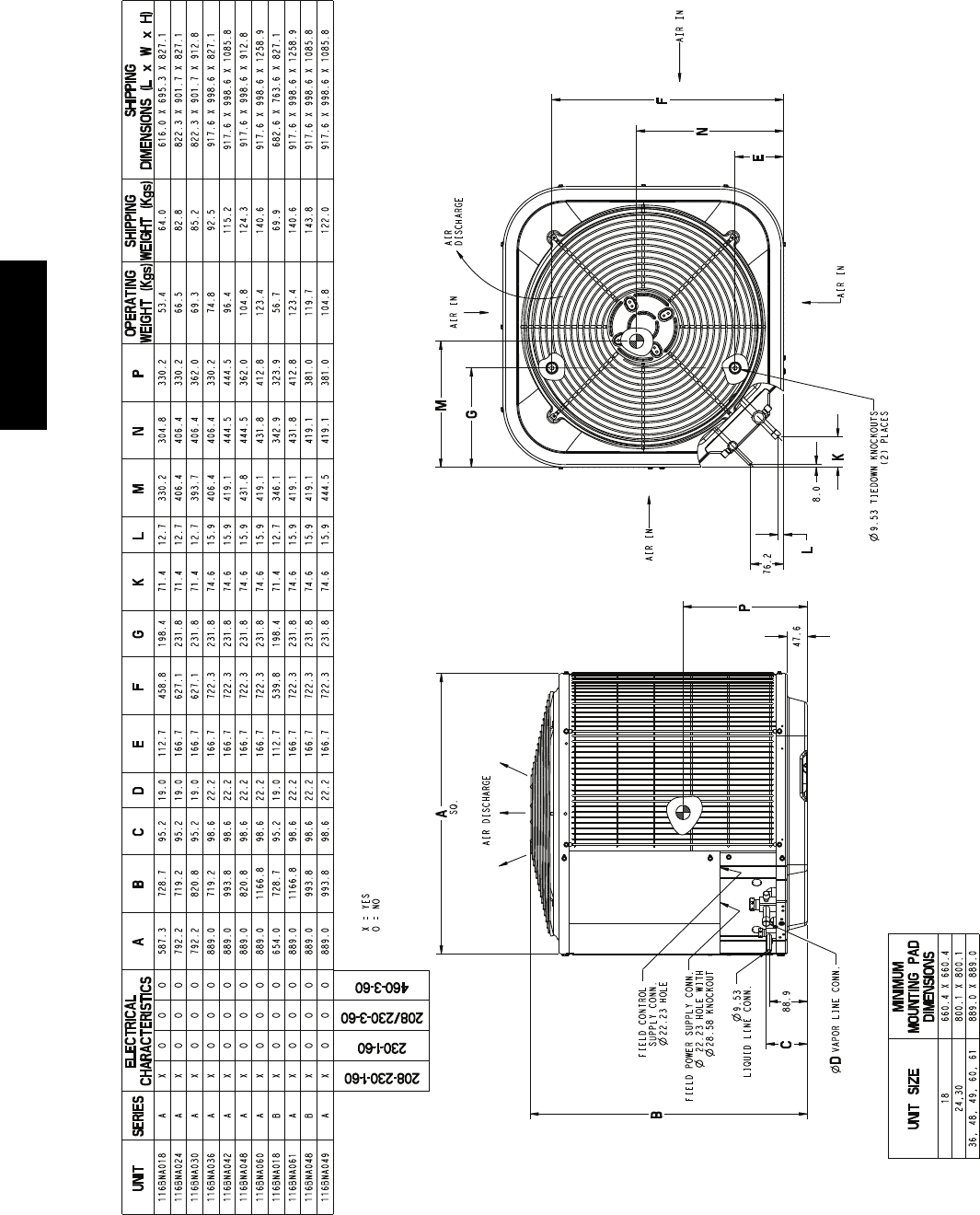
DIMENSIONS -- SI
B
C88.9
47.6
P
A
76.2
K
8.0
L
N
M
E
F
G
208-230-1-60
230-1-60
208/230-3-60
460-3-60
UNIT SERIES ELECTRICAL
CHARACTERISTICS ABCDEFGKLMNP
OPERATING
WEIGHT (Kgs)
SHIPPING
WEIGHT (Kgs)
SHIPPING
DIMENSIONS (L x W x H)
116BNA018 A X O O O 587.3 728.7 95.2 19.0 112.7 458.8 198.4 71.4 12.7 330.2 304.8 330.2 53.4 64.0 616.0 X 695.3 X 827.1
116BNA024 A X O O O 792.2 719.2 95.2 19.0 166.7 627.1 231.8 71.4 12.7 406.4 406.4 330.2 66.5 82.8 822.3 X 901.7 X 827.1
116BNA030 A X O O O 792.2 820.8 95.2 19.0 166.7 627.1 231.8 71.4 12.7 393.7 406.4 362.0 69.3 85.2 822.3 X 901.7 X 912.8
116BNA036 A X O O O 889.0 719.2 98.6 22.2 166.7 722.3 231.8 74.6 15.9 406.4 406.4 330.2 74.8 92.5 917.6 X 998.6 X 827.1
116BNA042 A X O O O 889.0 993.8 98.6 22.2 166.7 722.3 231.8 74.6 15.9 419.1 444.5 444.5 96.4 115.2 917.6 X 998.6 X 1085.8
116BNA048 A X O O O 889.0 820.8 98.6 22.2 166.7 722.3 231.8 74.6 15.9 431.8 444.5 362.0 104.8 124.3 917.6 X 998.6 X 912.8
116BNA060 A X O O O 889.0 1166.8 98.6 22.2 166.7 722.3 231.8 74.6 15.9 419.1 431.8 412.8 123.4 140.6 917.6 X 998.6 X 1258.9
116BNA018 B X O O O 654.0 728.7 95.2 19.0 112.7 539.8 198.4 71.4 12.7 346.1 342.9 323.9 56.7 69.9 682.6 X 763.6 X 827.1
116BNA061 A X O O O 889.0 1166.8 98.6 22.2 166.7 722.3 231.8 74.6 15.9 419.1 431.8 412.8 123.4 140.6 917.6 X 998.6 X 1258.9
116BNA048 B X O O O 889.0 993.8 98.6 22.2 166.7 722.3 231.8 74.6 15.9 419.1 419.1 381.0 119.7 143.8 917.6 X 998.6 X 1085.8
116BNA049 A X O O O 889.0 993.8 98.6 22.2 166.7 722.3 231.8 74.6 15.9 444.5 419.1 381.0 104.8 122.0 917.6 X 998.6 X 1085.8
UNIT SIZE
MINIMUM
MOUNTING PAD
DIMENSIONS
18 660.4 X 660.4
24,30 800.1 X 800.1
36, 48, 49, 60, 61 889.0 X 889.0
AIR DISCHARGE
SQ.
AIR
DISCHARGE
AIR IN
VAPOR LINE CONN.
D
9.53
LIQUID LINE CONN.
AIR IN
AIR IN
AIR IN
9.53 TIEDOWN KNOCKOUTS
(2) PLACES
FIELD CONTROL
SUPPLY CONN.
22.23 HOLE
FIELD POWER SUPPLY CONN.
22.23 HOLE WITH
28.58 KNOCKOUT
X = YES
O = NO
116B
11
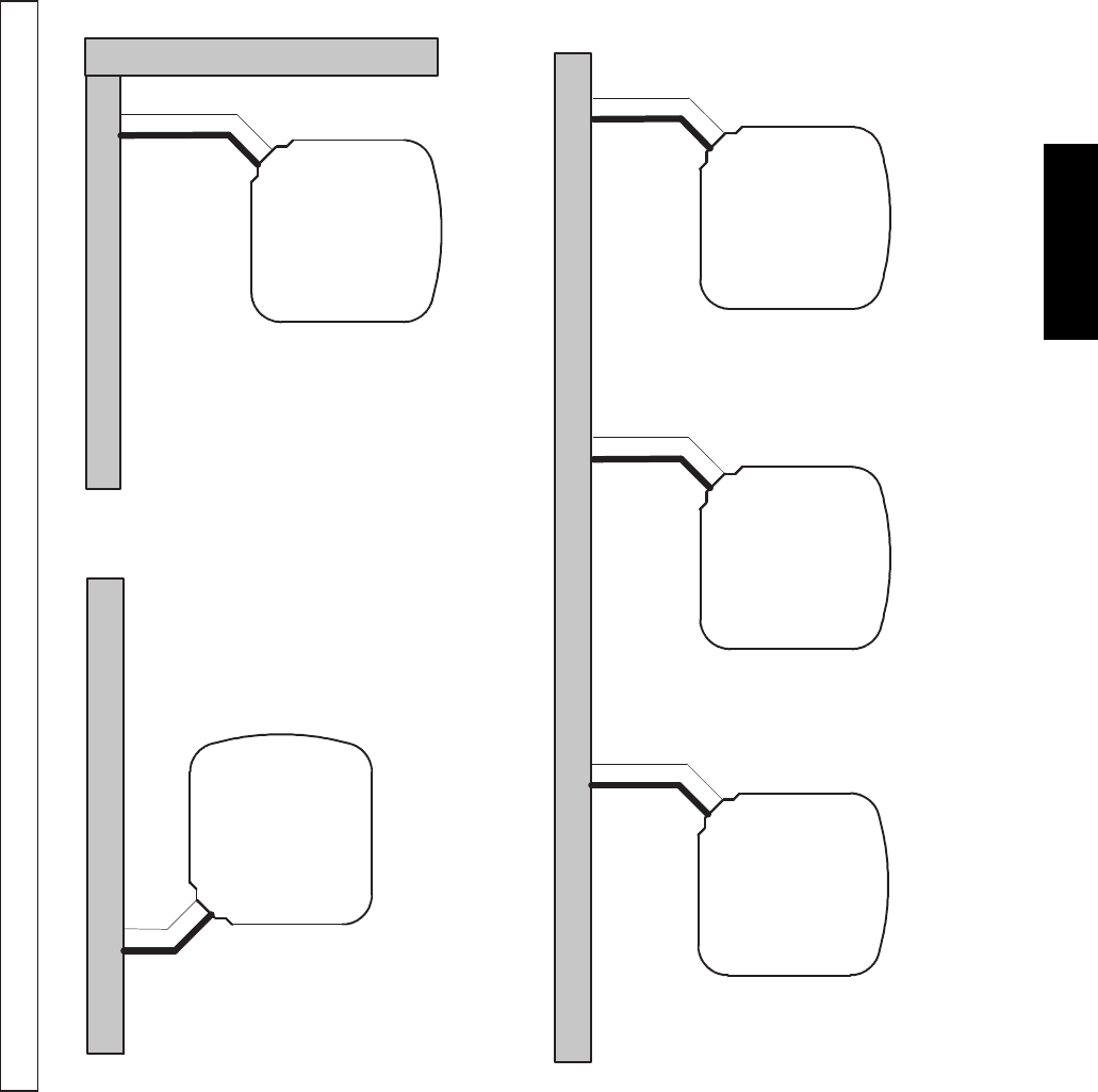
CLEARANCES
Clearances (various examples)
Wall
6”
(152.4)
24”
(609.6)
Service
Wall
Wall
Wall
12”
(304.8)
12”
(304.8)
18”
(457.2)
24”
(609.6)
Service
6”
(152.4)
12”
(304.8)
24”
(609.6)
Service
24”
(609.6)
Service
24”
(609.6)
Service
Note: Numbers in ( ) = mm
18”
(457.2)
18”
(457.2)
12”
(304.8)
IMPORTANT: When installing multiple units in an alcove, roof well, or partially enclosed area, ensure there is adequate ventilation to prevent re--circulation of discharge air.
116B
12
TESTED AHRI COMBINATION RATINGS*
NOTE: Ratings contained in this document are subject to change at any time.
For AHRI ratings certificates, please refer to the AHRI directory www.ahridirectory.org
Additional ratings and system combinations can be accessed via the Bryant database at:
http://cactaxcredits.info/bryant-ratings/hp_ratings_srch.php
Equipment performance calculator can be accessed at: http://rpmobbry.wrightsoft.com/
Model Number Indoor Coil Model Number Furnace Model Number Cooling Capacity EER SEER
116BNA018****B CNPV*1917A** 18,000 12.0 14.5
116BNA024****A CNPV*3117A** 23,600 12.0 14.5
116BNA030****A CNPV*3117A** 28,600 12.0 14.5
116BNA036****A CNPV*3717A** 34,400 12.0 14.5
116BNA042****A CNPV*4324A** 41,500 12.0 14.5
116BNA048****B CAP**6025A** 46,000 12.0 14.5
116BNA049****A CAP**6025A** 48,000 11.5 14.0
116BNA060****A CNPV*6124A** 56,000 12.0 14.5
116BNA061****A CNPV*6124A** 59,500 12.0 14.5
*AHRI = Air Conditioning, Heating & Refrigeration Institute
EER — Energy Efficiency Ratio
SEER — Seasonal Energy Efficiency Ratio
NOTES:
1. Ratings are net values reflecting the effects of circulating fan motor heat. Supplemental electric heat is not included.
2. Tested outdoor/indoor combinations have been tested in accordance with DOE test procedures for central air conditioners. Ratings for other combinations are determined under DOE
computer simulation procedures.
3. Determine actual CFM values obtainable for your system by referring to fan performance data in fan coil or furnace coil literature.
4. Do not apply with capillary tube coils as performance and reliability are affected.
116B
13
DETAILED COOLING CAPACITIES#
EVAPORATOR AIR CONDENSER ENTERING AIR TEMPERATURES ° F (° C)
75 (23.9) 85 (29.4) 95 (35) 105 (40.6) 115 (46.1) 125 (51.7)
CFM EWB
°F(°C)
Capacity MBtuh† To t al
System
KW**
Capacity MBtuh† To t al
System
KW**
Capacity MBtuh† Tot a l
System
KW**
Capacity MBtuh† To t al
System
KW**
Capacity MBtuh† To t al
System
KW**
Capacity MBtuh† Tot a l
System
KW**
Tot a l Sens‡ Tot al Sens‡ Tota l Sens‡ Tot al Sens‡ Tot al Sens‡ Tot a l Sens‡
116BNA018****B Outdoor Section With CNPV*1917A** Indoor Section
525
72 (22.2) 21.52 10.39 1.18 20.55 10.05 1.32 19.48 9.68 1.48 18.35 9.29 1.65 17.15 8.88 1.84 15.88 8.46 2.06
67 (19.4) 19.59 12.69 1.18 18.66 12.32 1.32 17.68 11.95 1.47 16.64 11.56 1.64 15.54 11.14 1.83 14.37 10.72 2.05
63 (17.2)†† 18.14 12.20 1.18 17.28 11.84 1.32 16.37 11.47 1.47 15.40 11.07 1.63 14.37 10.66 1.82 13.27 10.22 2.04
62 (16.7) 17.80 14.92 1.18 16.97 14.56 1.31 16.08 14.18 1.47 15.17 13.78 1.63 14.30 14.30 1.82 13.42 13.42 2.04
57 (13.9) 17.19 17.19 1.18 16.54 16.54 1.31 15.84 15.84 1.46 15.09 15.09 1.63 14.27 14.27 1.82 13.40 13.40 2.04
600
72 (22.2) 21.94 10.93 1.21 20.92 10.58 1.35 19.82 10.21 1.51 18.63 9.81 1.68 17.39 9.40 1.87 16.07 8.97 2.09
67 (19.4) 19.99 13.55 1.20 19.03 13.19 1.35 18.00 12.80 1.50 16.92 12.40 1.67 15.78 11.98 1.86 14.57 11.54 2.08
63 (17.2)†† 18.55 13.02 1.20 17.64 12.65 1.34 16.68 12.26 1.49 15.68 11.86 1.66 14.60 11.44 1.85 13.47 10.99 2.07
62 (16.7) 18.25 16.11 1.20 17.39 15.72 1.34 16.55 16.55 1.49 15.74 15.74 1.66 14.87 14.87 1.85 13.93 13.93 2.07
57 (13.9) 17.99 17.99 1.20 17.28 17.28 1.34 16.53 16.53 1.49 15.72 15.72 1.66 14.85 14.85 1.85 13.91 13.91 2.07
675
72 (22.2) 22.24 11.45 1.23 21.19 11.09 1.38 20.06 10.72 1.54 18.83 10.32 1.71 17.55 9.90 1.90 16.20 9.47 2.12
67 (19.4) 20.29 14.38 1.23 19.30 14.01 1.37 18.24 13.62 1.53 17.13 13.22 1.70 15.95 12.79 1.89 14.72 12.34 2.10
63 (17.2)†† 18.85 13.79 1.23 17.91 13.42 1.37 16.92 13.03 1.52 15.88 12.61 1.69 14.78 12.18 1.88 13.63 11.73 2.10
62 (16.7) 18.68 18.68 1.23 17.93 17.93 1.37 17.12 17.12 1.52 16.26 16.26 1.69 15.33 15.33 1.88 14.35 14.35 2.10
57 (13.9) 18.66 18.66 1.23 17.90 17.90 1.37 17.09 17.09 1.52 16.24 16.24 1.69 15.31 15.31 1.88 14.33 14.33 2.10
EVAPORATOR AIR CONDENSER ENTERING AIR TEMPERATURES ° F (° C)
75 (23.9) 85 (29.4) 95 (35) 105 (40.6) 115 (46.1) 125 (51.7)
CFM EWB
°F(°C)
Capacity MBtuh† To t al
System
KW**
Capacity MBtuh† To t al
System
KW**
Capacity MBtuh† Tot a l
System
KW**
Capacity MBtuh† To t al
System
KW**
Capacity MBtuh† To t al
System
KW**
Capacity MBtuh† Tot a l
System
KW**
Tot a l Sens‡ Tot al Sens‡ Tota l Sens‡ Tot al Sens‡ Tot al Sens‡ Tot a l Sens‡
116BNA024****A Outdoor Section With CNPV*3117A** Indoor Section
700
72 (22.2) 28.21 13.70 1.55 26.92 13.25 1.74 25.54 12.78 1.94 24.09 12.29 2.16 22.56 11.77 2.41 20.94 11.24 2.68
67 (19.4) 25.63 16.78 1.55 24.44 16.32 1.73 23.19 15.85 1.93 21.87 15.36 2.15 20.47 14.84 2.39 18.98 14.29 2.67
63 (17.2)†† 23.72 16.13 1.55 22.62 15.67 1.73 21.46 15.20 1.92 20.22 14.70 2.14 18.91 14.18 2.38 17.52 13.62 2.67
62 (16.7) 23.32 19.80 1.55 22.25 19.34 1.73 21.14 18.86 1.92 20.00 19.96 2.14 18.95 18.95 2.38 17.82 17.82 2.67
57 (13.9) 22.68 22.68 1.55 21.84 21.84 1.73 20.93 20.93 1.92 19.96 19.96 2.14 18.92 18.92 2.38 17.79 17.79 2.67
800
72 (22.2) 28.72 14.43 1.58 27.38 13.97 1.77 25.95 13.49 1.98 24.44 12.99 2.20 22.85 12.47 2.44 21.17 11.93 2.72
67 (19.4) 26.16 17.95 1.58 24.91 17.49 1.77 23.60 17.00 1.97 22.22 16.49 2.19 20.76 15.96 2.43 19.23 15.41 2.71
63 (17.2)†† 24.23 17.22 1.58 23.08 16.75 1.77 21.86 16.27 1.96 20.58 15.76 2.18 19.21 15.22 2.42 17.78 14.66 2.70
62 (16.7) 23.91 21.38 1.58 22.85 22.74 1.77 21.85 21.85 1.96 20.81 20.81 2.18 19.69 19.69 2.42 18.49 18.49 2.71
57 (13.9) 23.70 23.70 1.58 22.79 22.79 1.76 21.82 21.82 1.96 20.78 20.78 2.18 19.66 19.66 2.43 18.46 18.46 2.71
900
72 (22.2) 29.09 15.12 1.62 27.72 14.67 1.81 26.23 14.18 2.02 24.68 13.67 2.24 23.05 13.15 2.48 21.32 12.60 2.76
67 (19.4) 26.54 19.08 1.62 25.25 18.60 1.81 23.90 18.11 2.01 22.48 17.59 2.22 20.98 17.05 2.47 19.42 16.48 2.75
63 (17.2)†† 24.61 18.27 1.62 23.42 17.79 1.80 22.16 17.30 2.00 20.84 16.78 2.22 19.45 16.23 2.46 17.98 15.65 2.74
62 (16.7) 24.60 24.60 1.62 23.62 23.62 1.80 22.58 22.58 2.00 21.48 21.48 2.22 20.29 20.29 2.47 19.02 19.02 2.75
57 (13.9) 24.56 24.56 1.62 23.59 23.59 1.80 22.55 22.55 2.00 21.45 21.45 2.22 20.27 20.27 2.47 18.99 18.99 2.75
See notes on pg. 17
116B

14
DETAILED COOLING CAPACITIES# (CONT.)
EVAPORATOR AIR CONDENSER ENTERING AIR TEMPERATURES ° F (° C)
75 (23.9) 85 (29.4) 95 (35) 105 (40.6) 115 (46.1) 125 (51.7)
CFM EWB
°F(°C)
Capacity MBtuh† To t al
System
KW**
Capacity MBtuh† To t al
System
KW**
Capacity MBtuh† Tot a l
System
KW**
Capacity MBtuh† To t al
System
KW**
Capacity MBtuh† To t al
System
KW**
Capacity MBtuh† Tot a l
System
KW**
Tot a l Sens‡ Tot al Sens‡ Tota l Sens‡ Tot al Sens‡ Tot al Sens‡ Tot a l Sens‡
116BNA030****A Outdoor Section With CNPV*3117A** Indoor Section
875
72 (22.2) 34.09 16.61 1.91 32.58 16.09 2.11 31.00 15.56 2.33 29.32 15.00 2.59 27.51 14.40 2.88 25.53 13.76 3.22
67 (19.4) 30.99 20.47 1.92 29.61 19.95 2.12 28.16 19.41 2.34 26.61 18.84 2.59 24.93 18.23 2.88 23.10 17.56 3.22
63 (17.2)†† 28.76 19.68 1.93 27.47 19.16 2.12 26.11 18.61 2.34 24.65 18.03 2.59 23.07 17.41 2.88 21.33 16.73 3.22
62 (16.7) 28.31 24.28 1.93 27.08 23.74 2.12 25.80 23.16 2.34 24.56 24.56 2.59 23.28 23.28 2.88 21.87 21.87 3.21
57 (13.9) 27.76 27.76 1.93 26.76 26.76 2.12 25.69 25.69 2.34 24.52 24.52 2.59 23.25 23.25 2.88 21.83 21.83 3.21
1000
72 (22.2) 34.67 17.49 1.96 33.09 16.96 2.15 31.45 16.42 2.38 29.71 15.86 2.63 27.83 15.25 2.93 25.79 14.60 3.26
67 (19.4) 31.55 21.88 1.97 30.10 21.35 2.16 28.60 20.80 2.38 27.00 20.22 2.64 25.27 19.60 2.93 23.39 18.92 3.26
63 (17.2)†† 29.30 20.99 1.97 27.95 20.46 2.17 26.55 19.90 2.39 25.04 19.31 2.64 23.40 18.68 2.93 21.63 17.98 3.26
62 (16.7) 29.03 28.77 1.97 27.89 27.89 2.16 26.74 26.74 2.39 25.50 25.50 2.64 24.14 24.14 2.93 22.64 22.64 3.26
57 (13.9) 28.93 28.93 1.97 27.84 27.84 2.16 26.70 26.70 2.39 25.46 25.46 2.64 24.11 24.11 2.93 22.61 22.61 3.26
1125
72 (22.2) 35.09 18.33 2.00 33.45 17.80 2.20 31.76 17.25 2.42 29.97 16.67 2.68 28.04 16.06 2.97 25.96 15.41 3.31
67 (19.4) 31.96 23.24 2.01 30.47 22.70 2.21 28.93 22.14 2.43 27.29 21.54 2.68 25.52 20.90 2.97 23.62 20.20 3.31
63 (17.2)†† 29.70 22.25 2.02 28.32 21.71 2.21 26.87 21.14 2.43 25.32 20.53 2.69 23.66 19.88 2.98 21.87 19.15 3.31
62 (16.7) 29.93 29.93 2.02 28.78 28.78 2.21 27.57 27.57 2.43 26.26 26.26 2.68 24.83 24.83 2.97 23.26 23.26 3.31
57 (13.9) 29.89 29.89 2.02 28.74 28.74 2.21 27.53 27.53 2.43 26.22 26.22 2.68 24.80 24.80 2.97 23.23 23.23 3.31
EVAPORATOR AIR CONDENSER ENTERING AIR TEMPERATURES ° F (° C)
75 (23.9) 85 (29.4) 95 (35) 105 (40.6) 115 (46.1) 125 (51.7)
CFM EWB
°F(°C)
Capacity MBtuh† To t al
System
KW**
Capacity MBtuh† To t al
System
KW**
Capacity MBtuh† Tot a l
System
KW**
Capacity MBtuh† To t al
System
KW**
Capacity MBtuh† To t al
System
KW**
Capacity MBtuh† Tot a l
System
KW**
Tot a l Sens‡ Tot al Sens‡ Tota l Sens‡ Tot al Sens‡ Tot al Sens‡ Tot a l Sens‡
116BNA036****A Outdoor Section With CNPV*3717A** Indoor Section
1050
72 (22.2) 41.06 20.24 2.39 39.22 19.60 2.65 37.27 18.94 2.95 35.20 18.24 3.28 33.01 17.50 3.66 30.65 16.73 4.11
67 (19.4) 37.33 24.93 2.37 35.65 24.28 2.63 33.87 23.61 2.93 31.96 22.90 3.26 29.95 22.15 3.65 27.79 21.36 4.09
63 (17.2)†† 34.65 23.97 2.36 33.08 23.32 2.62 31.40 22.64 2.92 29.62 21.92 3.25 27.73 21.17 3.64 25.71 20.37 4.09
62 (16.7) 34.09 29.55 2.36 32.58 28.89 2.62 31.00 28.17 2.91 29.47 29.47 3.25 27.95 27.95 3.64 26.29 26.29 4.09
57 (13.9) 33.38 33.38 2.35 32.16 32.16 2.62 30.85 30.85 2.91 29.43 29.43 3.25 27.91 27.91 3.64 26.25 26.25 4.09
1200
72 (22.2) 41.77 21.32 2.45 39.84 20.66 2.72 37.82 19.99 3.01 35.67 19.28 3.35 33.39 18.53 3.73 30.96 17.75 4.17
67 (19.4) 38.02 26.65 2.43 36.25 25.99 2.70 34.40 25.30 2.99 32.44 24.58 3.32 30.35 23.82 3.71 28.13 23.01 4.15
63 (17.2)†† 35.31 25.57 2.42 33.66 24.91 2.69 31.93 24.22 2.98 30.09 23.48 3.31 28.13 22.71 3.70 26.05 21.89 4.15
62 (16.7) 34.94 31.83 2.42 33.53 33.53 2.69 32.12 32.12 2.98 30.60 30.60 3.32 28.97 28.97 3.70 27.21 27.21 4.15
57 (13.9) 34.80 34.80 2.42 33.47 33.47 2.68 32.07 32.07 2.98 30.55 30.55 3.32 28.93 28.93 3.70 27.17 27.17 4.15
1350
72 (22.2) 42.28 22.34 2.52 40.29 21.68 2.78 38.19 20.99 3.08 35.98 20.27 3.41 33.65 19.52 3.79 31.16 18.72 4.23
67 (19.4) 38.51 28.29 2.50 36.70 27.62 2.76 34.80 26.93 3.05 32.78 26.19 3.39 30.65 25.41 3.77 28.39 24.57 4.22
63 (17.2)†† 35.80 27.10 2.48 34.11 26.43 2.75 32.32 25.72 3.04 30.43 24.97 3.38 28.44 24.18 3.76 26.32 23.32 4.21
62 (16.7) 36.01 36.01 2.48 34.61 34.61 2.75 33.12 33.12 3.05 31.51 31.51 3.38 29.80 29.80 3.77 27.94 27.94 4.21
57 (13.9) 35.96 35.96 2.48 34.56 34.56 2.75 33.08 33.08 3.04 31.47 31.47 3.38 29.76 29.76 3.77 27.91 27.91 4.21
See notes on pg. 17
116B

15
DETAILED COOLING CAPACITIES# (CONT.)
EVAPORATOR AIR CONDENSER ENTERING AIR TEMPERATURES ° F (° C)
75 (23.9) 85 (29.4) 95 (35) 105 (40.6) 115 (46.1) 125 (51.7)
CFM EWB
°F(°C)
Capacity MBtuh† To t al
System
KW**
Capacity MBtuh† To t al
System
KW**
Capacity MBtuh† Tot a l
System
KW**
Capacity MBtuh† To t al
System
KW**
Capacity MBtuh† To t al
System
KW**
Capacity MBtuh† Tot a l
System
KW**
Tot a l Sens‡ Tot al Sens‡ Tota l Sens‡ Tot al Sens‡ Tot al Sens‡ Tot a l Sens‡
116BNA042****A Outdoor Section With CNPV*4324A** Indoor Section
1225
72 (22.2) 49.58 24.05 2.77 47.31 23.28 3.07 44.88 22.46 3.42 42.30 21.59 3.80 39.58 20.70 4.23 36.71 19.77 4.70
67 (19.4) 45.17 29.64 2.75 43.10 28.86 3.05 40.90 28.04 3.38 38.55 27.18 3.76 36.07 26.27 4.19 33.47 25.33 4.66
63 (17.2)†† 41.97 28.52 2.74 40.06 27.75 3.03 38.02 26.93 3.36 35.83 26.06 3.74 33.53 25.16 4.17 31.10 24.21 4.64
62 (16.7) 41.32 35.16 2.74 39.49 34.36 3.03 37.56 33.49 3.36 35.65 35.65 3.74 33.78 33.78 4.17 31.76 31.76 4.64
57 (13.9) 40.45 40.45 2.73 38.96 38.96 3.03 37.34 37.34 3.36 35.60 35.60 3.74 33.73 33.73 4.17 31.72 31.72 4.64
1400
72 (22.2) 50.40 25.29 2.85 48.02 24.50 3.15 45.48 23.66 3.49 42.82 22.79 3.87 39.99 21.88 4.30 37.02 20.94 4.77
67 (19.4) 45.95 31.63 2.82 43.80 30.84 3.12 41.50 30.00 3.46 39.07 29.12 3.84 36.51 28.20 4.26 33.83 27.23 4.74
63 (17.2)†† 42.74 30.38 2.81 40.75 29.59 3.10 38.61 28.75 3.44 36.36 27.87 3.82 33.97 26.94 4.24 31.47 25.96 4.71
62 (16.7) 42.31 37.80 2.81 40.55 40.55 3.10 38.82 38.82 3.44 36.94 36.94 3.82 34.93 34.93 4.25 32.78 32.78 4.72
57 (13.9) 42.10 42.10 2.81 40.50 40.50 3.10 38.76 38.76 3.44 36.89 36.89 3.82 34.89 34.89 4.25 32.74 32.74 4.72
1575
72 (22.2) 50.98 26.46 2.92 48.52 25.66 3.22 45.91 24.82 3.56 43.16 23.93 3.95 40.25 23.01 4.37 37.22 22.06 4.85
67 (19.4) 46.53 33.54 2.90 44.31 32.73 3.19 41.95 31.88 3.53 39.45 30.98 3.91 36.83 30.02 4.34 34.11 29.02 4.81
63 (17.2)†† 43.31 32.15 2.88 41.25 31.35 3.17 39.06 30.49 3.51 36.74 29.58 3.89 34.30 28.62 4.31 31.77 27.60 4.78
62 (16.7) 43.52 43.52 2.88 41.82 41.82 3.18 39.96 39.96 3.52 37.98 37.98 3.90 35.86 35.86 4.33 33.58 33.58 4.80
57 (13.9) 43.46 43.46 2.88 41.76 41.76 3.18 39.91 39.91 3.52 37.93 37.93 3.90 35.81 35.81 4.33 33.55 33.55 4.80
EVAPORATOR AIR CONDENSER ENTERING AIR TEMPERATURES ° F (° C)
75 (23.9) 85 (29.4) 95 (35) 105 (40.6) 115 (46.1) 125 (51.7)
CFM EWB
°F(°C)
Capacity MBtuh† To t al
System
KW**
Capacity MBtuh† To t al
System
KW**
Capacity MBtuh† Tot a l
System
KW**
Capacity MBtuh† To t al
System
KW**
Capacity MBtuh† To t al
System
KW**
Capacity MBtuh† Tot a l
System
KW**
Tot a l Sens‡ Tot al Sens‡ Tota l Sens‡ Tot al Sens‡ Tot al Sens‡ Tot a l Sens‡
116BNA048****B Outdoor Section With CAP**6024* Indoor Section
1400
72 (22.2) 55.71 27.90 2.67 52.91 26.91 3.09 50.01 25.90 3.52 47.00 24.87 3.95 43.85 23.81 4.41 40.51 22.69 4.89
67 (19.4) 50.48 34.32 2.83 47.96 33.34 3.22 45.37 32.35 3.61 42.67 31.33 4.01 39.85 30.28 4.44 36.84 29.16 4.91
63 (17.2)†† 46.73 32.94 2.93 44.44 31.98 3.29 42.06 31.01 3.66 39.59 30.00 4.05 36.99 28.96 4.46 34.22 27.85 4.92
62 (16.7) 45.93 40.65 2.94 43.75 39.65 3.30 41.55 41.29 3.66 39.51 39.51 4.04 37.39 37.39 4.46 35.08 35.08 4.91
57 (13.9) 45.05 45.05 2.96 43.28 43.28 3.31 41.43 41.43 3.66 39.45 39.45 4.04 37.34 37.34 4.46 35.03 35.03 4.91
1600
72 (22.2) 56.66 29.33 2.72 53.70 28.32 3.15 50.67 27.29 3.59 47.54 26.24 4.03 44.26 25.15 4.49 40.81 24.02 4.98
67 (19.4) 51.35 36.61 2.88 48.71 35.62 3.28 46.00 34.60 3.68 43.20 33.56 4.09 40.27 32.47 4.53 37.17 31.32 5.00
63 (17.2)†† 47.56 35.07 2.99 45.15 34.09 3.36 42.68 33.09 3.74 40.11 32.06 4.13 37.41 30.98 4.55 34.56 29.83 5.01
62 (16.7) 47.06 46.71 3.00 45.06 45.06 3.36 43.04 43.04 3.73 40.91 40.91 4.12 38.62 38.62 4.54 36.15 36.15 5.00
57 (13.9) 46.92 46.92 3.00 44.99 44.99 3.36 42.98 42.98 3.73 40.85 40.85 4.12 38.57 38.57 4.54 36.11 36.11 5.00
1800
72 (22.2) 57.33 30.68 2.77 54.27 29.65 3.22 51.13 28.60 3.66 47.88 27.53 4.11 44.52 26.43 4.57 40.96 25.28 5.07
67 (19.4) 51.99 38.81 2.94 49.25 37.79 3.35 46.46 36.75 3.76 43.57 35.67 4.17 40.57 34.55 4.62 37.43 33.33 5.09
63 (17.2)†† 48.17 37.10 3.06 45.68 36.10 3.44 43.11 35.07 3.82 40.47 34.01 4.21 37.72 32.88 4.64 34.82 31.65 5.10
62 (16.7) 48.51 48.51 3.04 46.44 46.44 3.41 44.29 44.29 3.79 42.02 42.02 4.19 39.60 39.60 4.62 36.98 36.98 5.09
57 (13.9) 48.45 48.45 3.04 46.38 46.38 3.42 44.24 44.24 3.79 41.97 41.97 4.19 39.55 39.55 4.62 36.94 36.94 5.09
See notes on pg. 17
116B
16
DETAILED COOLING CAPACITIES# (CONT.)
EVAPORATOR AIR CONDENSER ENTERING AIR TEMPERATURES ° F (° C)
75 (23.9) 85 (29.4) 95 (35) 105 (40.6) 115 (46.1) 125 (51.7)
CFM EWB
°F(°C)
Capacity MBtuh† To t al
System
KW**
Capacity MBtuh† To t al
System
KW**
Capacity MBtuh† Tot a l
System
KW**
Capacity MBtuh† To t al
System
KW**
Capacity MBtuh† To t al
System
KW**
Capacity MBtuh† Tot a l
System
KW**
Tot a l Sens‡ Tot al Sens‡ Tota l Sens‡ Tot al Sens‡ Tot al Sens‡ Tot a l Sens‡
116BNA049****A Outdoor Section With CAP**6024A* Indoor Section
1400
72 (22.2) 57.54 29.08 3.21 54.91 28.10 3.66 52.22 27.11 4.12 49.43 26.10 4.59 46.46 25.03 5.09 43.18 23.88 5.66
67 (19.4) 52.60 35.60 3.24 50.19 34.61 3.67 47.73 33.62 4.10 45.16 32.59 4.55 42.41 31.50 5.06 39.40 30.33 5.62
63 (17.2)†† 49.11 34.57 3.26 46.86 33.58 3.67 44.56 32.57 4.08 42.14 31.53 4.53 39.56 30.44 5.03 36.72 29.25 5.60
62 (16.7) 48.14 42.09 3.26 45.97 41.09 3.66 43.75 40.07 4.08 41.45 38.99 4.52 39.06 39.06 5.02 36.78 36.78 5.60
57 (13.9) 46.53 46.53 3.26 44.81 44.81 3.66 43.02 43.02 4.07 41.13 41.13 4.52 39.07 39.07 5.02 36.78 36.78 5.60
1600
72 (22.2) 58.62 30.51 3.27 55.85 29.51 3.73 53.04 28.50 4.19 50.14 27.47 4.66 47.06 26.39 5.17 43.67 25.22 5.74
67 (19.4) 53.60 37.89 3.30 51.08 36.88 3.74 48.50 35.86 4.17 45.83 34.82 4.63 42.99 33.72 5.13 39.88 32.52 5.70
63 (17.2)†† 50.08 36.71 3.32 47.72 35.70 3.74 45.31 34.68 4.16 42.81 33.63 4.61 40.14 32.51 5.11 37.20 31.30 5.68
62 (16.7) 49.23 45.22 3.32 46.99 44.16 3.74 44.76 44.49 4.16 42.69 42.69 4.61 40.49 40.49 5.11 38.05 38.05 5.68
57 (13.9) 48.50 48.50 3.33 46.64 46.64 3.74 44.72 44.72 4.16 42.69 42.69 4.61 40.50 40.50 5.11 38.05 38.05 5.68
1800
72 (22.2) 59.40 31.86 3.33 56.54 30.84 3.80 53.64 29.82 4.26 50.65 28.78 4.74 47.47 27.68 5.25 43.99 26.50 5.81
67 (19.4) 54.34 40.07 3.36 51.73 39.04 3.81 49.07 38.01 4.25 46.33 36.96 4.71 43.41 35.84 5.21 40.23 34.61 5.78
63 (17.2)†† 50.79 38.76 3.39 48.35 37.73 3.81 45.87 36.70 4.23 43.30 35.63 4.69 40.56 34.49 5.19 37.56 33.24 5.76
62 (16.7) 50.22 49.72 3.39 48.15 48.15 3.81 46.11 46.11 4.24 43.96 43.96 4.69 41.64 41.64 5.19 39.07 39.07 5.77
57 (13.9) 50.13 50.13 3.39 48.15 48.15 3.81 46.11 46.11 4.24 43.96 43.96 4.69 41.64 41.64 5.19 39.07 39.07 5.77
EVAPORATOR AIR CONDENSER ENTERING AIR TEMPERATURES ° F (° C)
75 (23.9) 85 (29.4) 95 (35) 105 (40.6) 115 (46.1) 125 (51.7)
CFM EWB
°F(°C)
Capacity MBtuh† To t al
System
KW**
Capacity MBtuh† To t al
System
KW**
Capacity MBtuh† Tot a l
System
KW**
Capacity MBtuh† To t al
System
KW**
Capacity MBtuh† To t al
System
KW**
Capacity MBtuh† Tot a l
System
KW**
Tot a l Sens‡ Tot al Sens‡ Tota l Sens‡ Tot al Sens‡ Tot al Sens‡ Tot a l Sens‡
116BNA060****A Outdoor Section With CNPV*6124A** Indoor Section
1750
72 (22.2) 67.62 33.62 3.61 64.17 32.46 4.00 60.58 31.27 4.41 56.79 30.03 4.86 52.77 28.73 5.37 48.49 27.36 5.94
67 (19.4) 61.61 41.91 3.60 58.55 40.77 3.97 55.32 39.59 4.38 51.90 38.34 4.83 48.28 37.03 5.33 44.39 35.62 5.90
63 (17.2)†† 57.26 40.25 3.60 54.46 39.14 3.96 51.50 37.96 4.36 48.36 36.73 4.80 45.00 35.42 5.31 41.41 34.01 5.88
62 (16.7) 56.64 50.02 3.59 54.07 53.77 3.96 51.61 51.61 4.36 48.99 48.99 4.81 46.15 46.15 5.32 43.04 43.04 5.90
57 (13.9) 56.19 56.19 3.59 53.95 53.95 3.96 51.53 51.53 4.36 48.93 48.93 4.81 46.09 46.09 5.32 42.99 42.99 5.90
2000
72 (22.2) 68.55 35.38 3.71 64.97 34.21 4.10 61.24 32.99 4.51 57.31 31.73 4.96 53.16 30.40 5.47 48.76 29.01 6.04
67 (19.4) 62.54 44.78 3.70 59.34 43.61 4.07 56.00 42.40 4.48 52.47 41.12 4.93 48.74 39.76 5.43 44.80 38.28 6.01
63 (17.2)†† 58.17 42.92 3.69 55.24 41.77 4.06 52.18 40.57 4.46 48.93 39.29 4.90 45.49 37.93 5.41 41.84 36.44 5.99
62 (16.7) 58.38 58.38 3.69 55.95 55.95 4.06 53.34 53.34 4.47 50.54 50.54 4.92 47.51 47.51 5.42 44.19 44.19 6.00
57 (13.9) 58.30 58.30 3.69 55.88 55.88 4.06 53.28 53.28 4.46 50.48 50.48 4.92 47.45 47.45 5.42 44.14 44.14 6.00
2250
72 (22.2) 69.20 37.05 3.81 65.50 35.85 4.20 61.65 34.62 4.61 57.62 33.34 5.06 53.39 32.00 5.57 48.89 30.59 6.14
67 (19.4) 63.21 47.52 3.80 59.93 46.32 4.17 56.49 45.07 4.58 52.89 43.73 5.03 49.12 42.29 5.53 45.19 44.77 6.11
63 (17.2)†† 58.84 45.45 3.79 55.83 44.27 4.16 52.68 43.02 4.56 49.37 41.69 5.01 45.89 40.23 5.51 42.31 42.31 6.09
62 (16.7) 60.10 60.10 3.79 57.51 57.51 4.16 54.74 54.74 4.57 51.77 51.77 5.02 48.57 48.57 5.53 45.09 45.09 6.11
57 (13.9) 60.03 60.03 3.79 57.44 57.44 4.16 54.68 54.68 4.57 51.71 51.71 5.02 48.52 48.52 5.53 45.04 45.04 6.11
See notes on pg. 17
116B
17
DETAILED COOLING CAPACITIES# (CONT.)
EVAPORATOR AIR CONDENSER ENTERING AIR TEMPERATURES ° F (° C)
75 (23.9) 85 (29.4) 95 (35) 105 (40.6) 115 (46.1) 125 (51.7)
CFM EWB
°F(°C)
Capacity MBtuh† To t al
System
KW**
Capacity MBtuh† To t al
System
KW**
Capacity MBtuh† Tot a l
System
KW**
Capacity MBtuh† To t al
System
KW**
Capacity MBtuh† To t al
System
KW**
Capacity MBtuh† Tot a l
System
KW**
Tot a l Sens‡ Tot al Sens‡ Tota l Sens‡ Tot al Sens‡ Tot al Sens‡ Tot a l Sens‡
116BNA061****A Outdoor Section With CNPV*6124A**+TDR Indoor Section
1750
72 (22.2) 68.26 35.40 3.65 65.62 34.24 4.19 62.70 33.02 4.80 59.44 31.72 5.50 55.84 30.35 6.31 51.84 28.89 7.25
67 (19.4) 62.16 43.65 3.59 59.80 42.52 4.12 57.18 41.32 4.72 54.27 40.05 5.42 51.03 38.69 6.24 47.43 37.23 7.18
62 (16.7) 56.92 51.79 3.54 54.89 50.66 4.07 52.67 49.40 4.67 50.45 50.45 5.37 48.08 48.08 6.19 45.35 45.35 7.15
57 (13.9) 55.79 55.79 3.53 54.23 54.23 4.06 52.43 52.43 4.67 50.37 50.37 5.37 48.01 48.01 6.19 45.29 45.29 7.15
2000
72 (22.2) 69.37 37.22 3.75 66.58 36.03 4.29 63.50 34.78 4.91 60.12 33.47 5.61 56.36 32.08 6.43 52.22 30.60 7.37
67 (19.4) 63.22 46.57 3.69 60.75 45.42 4.22 58.00 44.20 4.83 54.96 42.90 5.54 51.60 41.51 6.35 47.88 40.00 7.30
62 (16.7) 58.30 55.64 3.64 56.40 56.40 4.18 54.43 54.43 4.79 52.18 52.18 5.50 49.62 49.62 6.32 46.69 46.69 7.28
57 (13.9) 58.04 58.04 3.64 56.32 56.32 4.17 54.35 54.35 4.79 52.12 52.12 5.50 49.56 49.56 6.32 46.64 46.64 7.28
2250
72 (22.2) 70.16 38.93 3.85 67.25 37.73 4.39 64.06 36.47 5.01 60.55 35.14 5.72 56.68 33.73 6.54 52.43 32.24 7.48
67 (19.4) 64.02 49.36 3.79 61.43 48.19 4.32 58.58 46.94 4.94 55.46 45.61 5.65 52.01 44.17 6.47 48.25 42.59 7.41
62 (16.7) 59.97 59.97 3.75 58.12 58.12 4.29 55.99 55.99 4.91 53.58 53.58 5.62 50.85 50.85 6.45 47.74 47.74 7.41
57 (13.9) 59.89 59.89 3.75 58.04 58.04 4.29 55.93 55.93 4.91 53.52 53.52 5.62 50.79 50.79 6.45 47.69 47.69 7.40
{Total and sensible capacities are net capacities. Blower motor heat has been subtracted.
}Sensible capacities shown are based on 80_F(27_C) entering air at the indoor coil. For sensible capacities at other than 80_F(27_C), deduct 835 Btuh (245 kW) per 1000 CFM (480 L/S) of indoor coil air for each degree below
80_F(27_C), or add 835 Btuh (245 kW) per 1000 CFM (480 L/S) of indoor coil air per degree above 80_F(27_C).
# Detailed cooling capacities are based on indoor and outdoor unit at the same elevation per AHRI standard 210/240---2008. If additional tubing length and/or indoor unit is located above outdoor unit, a slight variation in capacity
may occur.
** System kw is total of indoor and outdoor unit kilowatts.
{{ At TVA rating indoor condition (75_F edb/63_F ewb). All other indoor air temperatures are at 80_F edb.
NOTE: When the required data falls between the published data, interpolation may be performed. Extrapolation is not an acceptable practice.
EWB — Entering Wet Bulb
116B
18
CONDENSER ONLY RATINGS
SST
°F(°C)
CONDENSER ENTERING AIR TEMPERATURES ° F (° C)
55 (12.78) 65 (18.33) 75 (23.89) 85 (29.44) 95 (35.0) 105 (40.56) 115 (46.11) 125 (51.67)
116BNA018****B
30
( --- 1.11)
TCG 15.70 14.90 14.10 13.20 12.30 11.30 10.20 9.20
SDT 66.60 76.20 85.80 95.30 104.80 114.30 123.70 133.10
KW 0.75 0.87 0.99 1.12 1.26 1.41 1.60 1.81
35
(1.67)
TCG 17.50 16.60 15.70 14.70 13.70 12.60 11.50 10.30
SDT 67.80 77.30 86.80 96.30 105.70 115.10 124.40 133.80
KW 0.75 0.87 0.99 1.12 1.26 1.42 1.60 1.81
40
(4.44)
TCG 19.40 18.40 17.40 16.30 15.20 14.00 12.80 11.50
SDT 69.00 78.50 87.90 97.30 106.60 115.90 125.20 134.50
KW 0.74 0.87 0.99 1.12 1.26 1.42 1.60 1.81
45
(7.22)
TCG 21.50 20.30 19.20 18.00 16.70 15.50 14.10 12.80
SDT 70.40 79.70 89.00 98.30 107.60 116.90 126.10 135.30
KW 0.74 0.86 0.99 1.13 1.27 1.43 1.61 1.82
50
(10.0)
TCG 23.60 22.40 21.10 19.70 18.40 17.00 15.60 14.10
SDT 71.60 80.90 90.10 99.40 108.60 117.80 127.00 136.20
KW 0.73 0.86 1.00 1.13 1.28 1.44 1.62 1.82
55
(12.78)
TCG 25.90 24.50 23.10 21.60 20.10 18.60 17.10 15.50
SDT 73.00 82.10 91.30 100.50 109.70 118.80 128.00 137.10
KW 0.73 0.86 1.00 1.14 1.29 1.45 1.63 1.84
116BNA024****A
30
( --- 1.11)
TCG 20.30 19.40 18.30 17.20 16.10 14.80 13.60 12.20
SDT 66.10 75.80 85.30 94.90 104.40 114.00 123.40 132.80
KW 1.00 1.15 1.30 1.47 1.65 1.85 2.09 2.36
35
(1.67)
TCG 22.60 21.40 20.30 19.10 17.80 16.50 15.10 13.60
SDT 67.20 76.80 86.30 95.80 105.30 114.70 124.10 133.50
KW 0.99 1.14 1.30 1.47 1.65 1.86 2.09 2.36
40
(4.44)
TCG 24.90 23.70 22.40 21.00 19.60 18.20 16.70 15.10
SDT 68.40 77.90 87.30 96.70 106.10 115.50 124.80 134.10
KW 0.98 1.14 1.30 1.47 1.66 1.86 2.09 2.36
45
(7.22)
TCG 27.40 26.00 24.60 23.10 21.60 20.10 18.40 16.70
SDT 69.60 79.00 88.30 97.70 107.00 116.30 125.60 134.90
KW 0.97 1.14 1.30 1.48 1.66 1.87 2.10 2.37
50
(10.0)
TCG 30.10 28.60 27.00 25.40 23.70 22.00 20.20 18.40
SDT 70.80 80.10 89.40 98.70 107.90 117.20 126.40 135.60
KW 0.96 1.13 1.30 1.48 1.67 1.88 2.11 2.37
55
(12.78)
TCG 33.00 31.30 29.50 27.70 25.90 24.10 22.10 20.20
SDT 72.10 81.30 90.50 99.70 108.90 118.10 127.30 136.40
KW 0.95 1.13 1.31 1.49 1.68 1.89 2.12 2.39
116BNA030****A
30
( --- 1.11)
TCG 24.90 23.50 22.20 20.80 19.40 17.90 16.20 14.40
SDT 68.10 77.50 87.00 96.40 105.80 115.10 124.40 133.60
KW 1.27 1.43 1.60 1.78 1.99 2.23 2.50 2.81
35
(1.67)
TCG 27.50 26.00 24.50 23.10 21.50 19.90 18.10 16.20
SDT 69.40 78.70 88.10 97.40 106.70 116.00 125.30 134.40
KW 1.28 1.44 1.61 1.79 2.00 2.24 2.51 2.82
40
(4.44)
TCG 30.30 28.60 27.10 25.50 23.80 22.00 20.10 18.10
SDT 70.70 79.90 89.20 98.50 107.70 117.00 126.20 135.30
KW 1.29 1.44 1.61 1.80 2.01 2.25 2.52 2.83
45
(7.22)
TCG 33.30 31.50 29.80 28.00 26.20 24.30 22.30 20.10
SDT 72.00 81.20 90.40 99.60 108.80 118.00 127.20 136.30
KW 1.29 1.44 1.61 1.80 2.01 2.26 2.53 2.85
50
(10.0)
TCG 36.50 34.50 32.60 30.70 28.80 26.70 24.50 22.20
SDT 73.50 82.50 91.70 100.80 110.00 119.20 128.20 137.20
KW 1.29 1.44 1.61 1.80 2.02 2.26 2.54 2.86
55
(12.78)
TCG 39.90 37.80 35.70 33.60 31.50 29.30 26.90 24.40
SDT 75.00 84.00 93.00 102.10 111.20 120.30 129.30 138.20
KW 1.29 1.44 1.61 1.80 2.02 2.27 2.54 2.86
See notes on page 20
116B
19
CONDENSER ONLY RATINGS CONTINUED
SST
°F(°C)
CONDENSER ENTERING AIR TEMPERATURES ° F (° C)
55 (12.78) 65 (18.33) 75 (23.89) 85 (29.44) 95 (35.0) 105 (40.56) 115 (46.11) 125 (51.67)
116BNA036****A
30
( --- 1.11)
TCG 31.50 29.90 28.30 26.60 24.80 22.90 21.00 18.90
SDT 68.90 78.20 87.50 96.80 106.20 115.50 124.90 134.20
KW 1.50 1.73 1.96 2.21 2.50 2.82 3.21 3.66
35
(1.67)
TCG 34.80 33.00 31.20 29.40 27.40 25.40 23.30 21.10
SDT 70.10 79.30 88.60 97.90 107.20 116.50 125.80 135.00
KW 1.50 1.73 1.97 2.22 2.51 2.83 3.21 3.66
40
(4.44)
TCG 38.30 36.40 34.40 32.40 30.30 28.10 25.80 23.40
SDT 71.40 80.60 89.80 99.00 108.20 117.40 126.70 135.90
KW 1.51 1.74 1.98 2.24 2.52 2.85 3.22 3.66
45
(7.22)
TCG 42.10 40.00 37.80 35.60 33.30 30.90 28.40 25.80
SDT 72.80 81.90 91.00 100.20 109.40 118.50 127.70 136.80
KW 1.52 1.75 1.99 2.25 2.54 2.86 3.24 3.67
50
(10.0)
TCG 46.20 43.90 41.50 39.00 36.50 33.90 31.20 28.40
SDT 74.40 83.30 92.40 101.50 110.50 119.60 128.70 137.70
KW 1.53 1.77 2.01 2.27 2.56 2.88 3.25 3.68
55
(12.78)
TCG 50.50 47.90 45.30 42.70 39.90 37.10 34.20 31.10
SDT 76.00 84.90 93.80 102.80 111.80 120.80 129.80 138.70
KW 1.55 1.79 2.04 2.30 2.58 2.91 3.28 3.70
116BNA042****A
30
( --- 1.11)
TCG 37.90 36.20 34.30 32.30 30.10 27.90 25.50 23.00
SDT 69.80 79.20 88.70 98.10 107.40 116.70 125.90 135.10
KW 1.83 2.03 2.26 2.54 2.86 3.22 3.63 4.09
35
(1.67)
TCG 41.90 40.00 37.90 35.70 33.30 30.80 28.30 25.60
SDT 71.20 80.60 89.90 99.20 108.40 117.70 126.80 136.00
KW 1.84 2.04 2.28 2.56 2.88 3.24 3.65 4.10
40
(4.44)
TCG 46.10 44.00 41.70 39.20 36.70 34.00 31.20 28.30
SDT 72.70 81.90 91.20 100.40 109.60 118.70 127.80 136.90
KW 1.85 2.05 2.30 2.58 2.90 3.26 3.67 4.13
45
(7.22)
TCG 50.70 48.30 45.80 43.10 40.20 37.30 34.30 31.10
SDT 74.20 83.30 92.50 101.60 110.80 119.80 128.90 137.90
KW 1.86 2.07 2.32 2.60 2.92 3.29 3.70 4.15
50
(10.0)
TCG 55.50 52.90 50.10 47.10 44.00 40.80 37.50 34.10
SDT 75.80 84.80 93.90 103.00 112.00 121.00 130.00 138.90
KW 1.87 2.09 2.34 2.63 2.95 3.32 3.73 4.19
55
(12.78)
TCG 60.70 57.70 54.60 51.30 47.90 44.40 40.80 37.10
SDT 77.40 86.40 95.40 104.40 113.40 122.30 131.20 140.00
KW 1.89 2.11 2.36 2.66 2.99 3.36 3.77 4.22
116BNA048****B
30
( --- 1.11)
TCG 42.80 40.60 38.30 36.00 33.60 31.10 28.50 25.80
SDT 67.80 77.20 86.60 96.00 105.40 114.70 124.00 133.30
KW 2.00 2.29 2.58 2.87 3.17 3.51 3.90 4.35
35
(1.67)
TCG 47.40 44.80 42.30 39.70 37.10 34.40 31.60 28.60
SDT 69.00 78.30 87.70 97.00 106.30 115.60 124.80 134.10
KW 1.93 2.25 2.56 2.87 3.19 3.53 3.92 4.36
40
(4.44)
TCG 52.30 49.50 46.60 43.80 40.90 37.90 34.90 31.60
SDT 70.40 79.60 88.80 98.00 107.20 116.50 125.70 134.80
KW 1.82 2.18 2.52 2.85 3.19 3.55 3.94 4.38
45
(7.22)
TCG 57.80 54.60 51.40 48.20 45.00 41.70 38.30 34.80
SDT 71.80 80.80 90.00 99.10 108.30 117.40 126.60 135.70
KW 1.68 2.07 2.45 2.81 3.17 3.55 3.95 4.40
50
(10.0)
TCG 63.70 60.10 56.50 52.90 49.40 45.70 42.00 38.10
SDT 73.20 82.20 91.30 100.30 109.40 118.50 127.50 136.50
KW 1.49 1.93 2.34 2.74 3.13 3.53 3.95 4.41
55
(12.78)
TCG 70.10 66.00 62.00 58.00 54.10 50.00 45.90 41.60
SDT 74.70 83.70 92.60 101.60 110.60 119.60 128.50 137.40
KW 1.25 1.74 2.20 2.63 3.06 3.49 3.94 4.41
See notes on page 20
116B
20
CONDENSER ONLY RATINGS CONTINUED
SST
°F(°C)
CONDENSER ENTERING AIR TEMPERATURES ° F (° C)
55 (12.78) 65 (18.33) 75 (23.89) 85 (29.44) 95 (35.0) 105 (40.56) 115 (46.11) 125 (51.67)
116BNA049****A
30
( --- 1.11)
TCG 45.00 42.40 39.90 37.40 34.90 32.30 29.50 26.40
SDT 70.30 79.50 88.90 98.20 107.60 116.90 126.20 135.40
KW 2.04 2.41 2.75 3.08 3.44 3.84 4.32 4.89
35
(1.67)
TCG 49.80 46.80 44.00 41.20 38.50 35.60 32.60 29.30
SDT 71.70 80.90 90.10 99.40 108.70 118.00 127.20 136.30
KW 1.99 2.39 2.75 3.10 3.47 3.87 4.34 4.90
40
(4.44)
TCG 54.90 51.50 48.40 45.30 42.20 39.10 35.80 32.30
SDT 73.20 82.40 91.50 100.70 109.90 119.00 128.20 137.20
KW 1.93 2.36 2.75 3.12 3.50 3.91 4.38 4.92
45
(7.22)
TCG 60.40 56.60 53.00 49.60 46.20 42.80 39.30 35.50
SDT 74.80 83.90 92.90 102.00 111.10 120.20 129.20 138.10
KW 1.86 2.33 2.75 3.14 3.53 3.95 4.41 4.94
50
(10.0)
TCG 66.20 62.00 58.00 54.20 50.50 46.70 42.90 38.70
SDT 76.40 85.50 94.50 103.40 112.40 121.40 130.30 139.10
KW 1.78 2.28 2.73 3.15 3.56 3.99 4.45 4.98
55
(12.78)
TCG 72.40 67.70 63.20 59.10 55.00 50.90 46.70 42.10
SDT 78.20 87.10 96.10 104.90 113.80 122.60 131.40 140.10
KW 1.68 2.23 2.71 3.16 3.59 4.02 4.49 5.01
116BNA060****A
30
( --- 1.11)
TCG 49.90 47.50 45.10 42.40 39.60 36.70 33.50 30.20
SDT 70.90 80.40 89.80 99.20 108.50 117.80 127.00 136.30
KW 2.31 2.60 2.90 3.24 3.61 4.05 4.56 5.17
35
(1.67)
TCG 55.30 52.60 49.80 46.90 43.90 40.70 37.30 33.80
SDT 72.50 81.80 91.20 100.50 109.70 118.90 128.10 137.30
KW 2.31 2.61 2.93 3.27 3.65 4.08 4.59 5.19
40
(4.44)
TCG 61.00 58.00 54.90 51.70 48.40 45.00 41.40 37.60
SDT 74.10 83.40 92.60 101.80 111.00 120.10 129.20 138.30
KW 2.31 2.63 2.95 3.29 3.68 4.12 4.63 5.22
45
(7.22)
TCG 67.20 63.80 60.30 56.90 53.30 49.60 45.70 41.70
SDT 75.80 84.90 94.10 103.20 112.30 121.40 130.40 139.40
KW 2.31 2.64 2.97 3.32 3.71 4.15 4.66 5.25
50
(10.0)
TCG 73.70 70.00 66.20 62.40 58.50 54.50 50.40 46.10
SDT 77.60 86.60 95.70 104.70 113.70 122.70 131.60 140.50
KW 2.31 2.65 2.99 3.35 3.75 4.19 4.70 5.28
55
(12.78)
TCG 80.80 76.60 72.40 68.30 64.00 59.80 55.30 50.70
SDT 79.50 88.40 97.30 106.20 115.20 124.00 132.90 141.60
KW 2.31 2.66 3.02 3.39 3.79 4.24 4.74 5.32
116BNA061****A
30
( --- 1.11)
TCG 47.40 46.30 45.00 43.40 41.50 39.30 36.80 33.80
SDT 70.70 80.00 89.20 98.50 107.70 116.90 126.00 135.10
KW 1.95 2.35 2.79 3.30 3.90 4.61 5.45 6.46
35
(1.67)
TCG 52.30 51.10 49.60 47.90 45.90 43.40 40.70 37.40
SDT 72.20 81.40 90.60 99.70 108.90 118.00 127.00 136.00
KW 1.98 2.38 2.82 3.34 3.94 4.65 5.49 6.49
40
(4.44)
TCG 57.60 56.20 54.60 52.70 50.40 47.80 44.80 41.20
SDT 73.90 82.90 92.00 101.00 110.10 119.10 128.10 137.00
KW 2.01 2.41 2.86 3.38 3.99 4.70 5.54 6.53
45
(7.22)
TCG 63.20 61.70 59.90 57.80 55.30 52.40 49.00 45.20
SDT 75.60 84.50 93.50 102.50 111.40 120.40 129.20 138.10
KW 2.05 2.45 2.91 3.43 4.04 4.75 5.59 6.58
50
(10.0)
TCG 69.20 67.50 65.50 63.20 60.40 57.20 53.50 49.40
SDT 77.40 86.20 95.10 104.00 112.80 121.70 130.40 139.10
KW 2.09 2.50 2.96 3.49 4.10 4.82 5.65 6.64
55
(12.78)
TCG 75.60 73.70 71.40 68.80 65.70 62.20 58.20 53.60
SDT 79.30 88.00 96.80 105.60 114.30 123.00 131.70 140.30
KW 2.14 2.56 3.03 3.56 4.17 4.89 5.72 6.70
* AHRI listing applies only to systems shown in Combination Ratings table.
KW --- Outdoor Unit Kilowatts Only.
SDT --- Saturated Temperature Leaving Compressor (° F)
SST --- Saturated Temperature Entering Compressor (° F/° C)
TCG --- Gross Cooling Capacity (1000 Btuh)
116B

21
GUIDE SPECIFICATIONS
GENERAL
System Description
Outdoor--mounted, air--cooled, split--system air conditioner unit
suitable for ground or rooftop installation. Unit consists of a
hermetic compressor, an air--cooled coil, propeller--type
condenser fan, and a control box. Unit will discharge supply air
upward as shown on contract drawings. Unit will be used in a
refrigeration circuit to match up to a packaged fan coil or coil
unit.
Quality Assurance
— Unit will be rated in accordance with the latest edition
of AHRI Standard 210.
— Unit will be certified for capacity and efficiency, and
listed in the latest AHRI directory.
— Unit construction will comply with latest edition of
ANSI/ ASHRAE and with NEC.
— Unit will be constructed in accordance with UL
standards and will carry the UL label of approval. Unit
will have c--UL--us approval.
— Unit cabinet will be capable of withstanding Federal
Test Method Standard No. 141 (Method 6061) 500--hr
salt spray test.
— Air--cooled condenser coils will be leak tested at 150
psig and pressure tested at 450 psig.
— Unit constructed in ISO9001 approved facility.
Delivery, Storage, and Handling
— Unit will be shipped as single package only and is
stored and handled per unit manufacturer’s
recommendations.
Warranty (for inclusion by specifying engineer)
— U.S. and Canada only.
PRODUCTS
Equipment
Factory assembled, single piece, air--cooled air conditioner unit.
Contained within the unit enclosure is all factory wiring, piping,
controls, compressor, refrigerant charge Puronr(R--410A), and
special features required prior to field start--up.
Unit Cabinet
— Unit cabinet will be constructed of galvanized steel,
bonderized, and coated with a powder coat paint.
AIR--COOLED, SPLIT--SYSTEM AIR CONDITIONER
116B
1--1/2 TO 5 NOMINAL TONS
Fans
— Condenser fan will be direct--drive propeller type,
discharging air upward.
— Condenser fan motors will be totally enclosed, 1--phase
type with class B insulation and permanently lubricated
bearings. Shafts will be corrosion resistant.
— Fan blades will be statically and dynamically balanced.
— Condenser fan openings will be equipped with coated
steel wire safety guards.
Compressor
— Compressor will be hermetically sealed.
— Compressor will be mounted on rubber vibration
isolators.
Condenser Coil
— Condenser coil will be air cooled.
— Coil will be constructed of aluminum fins mechanically
bonded to copper tubes which are then cleaned,
dehydrated, and sealed.
Refrigeration Components
— Refrigeration circuit components will include
liquid--line shutoff valve with sweat connections,
vapor--line shutoff valve with sweat connections,
system charge of Puronr(R--410A) refrigerant, and
compressor oil.
— Unit will be equipped with filter drier for Puron
refrigerant.
Operating Characteristics
— The capacity of the unit will meet or exceed _____
Btuh at a suction temperature of _____ _F/_C. The
power consumption at full load will not exceed _____
kW.
— Combination of the unit and the evaporator or fan coil
unit will have a total net cooling capacity of _____
Btuh or greater at conditions of _____ CFM entering
air temperature at the evaporator at _____ _F/_Cwet
bulb and _____ _F/_C dry bulb, and air entering the
unit at _____ _F/_C.
— The system will have a SEER of _____ Btuh/watt or
greater at DOE conditions.
Electrical Requirements
— Nominal unit electrical characteristics will be _____ v,
single phase, 60 hz. The unit will be capable of
satisfactory operation within voltage limits of _____ v
to _____ v.
— Unit electrical power will be single point connection.
— Control circuit will be 24v.
Special Features
— Refer to section of this literature identifying accessories
and descriptions for specific features and available
enhancements.
116B

22
SYSTEM DESIGN SUMMARY
1. Intended for outdoor installation with free air inlet and outlet. Outdoor fan external static pressure available is less than 0.01--in. wc.
2. Minimum outdoor operating air temperature for cooling mode without low--ambient operation accessory is 55_F (12.8_C).
3. Maximum outdoor operating air temperature is 125_F (51.7_C).
4. For reliable operation, unit should be level in all horizontal planes.
5. For interconnecting refrigerant tube lengths greater than 80 ft (23.4 m) and/or 35 ft (10.7 m) vertical differential, consult Residential
Piping and Longline Guideline and Service Manual available from equipment distributor.
6. If any refrigerant tubing is buried, provide a 6 in. (152.4 mm) vertical rise to the valve connections at the unit. Refrigerant tubing
lengths up to 36 in. (914.4 mm) may be buried without further consideration. Do not bury refrigerant lines longer than 36 in. (914.4
mm).
7. Use only copper wire for electric connection at unit. Aluminum and clad aluminum are not acceptable for the type of connector
provided.
8. Do not apply capillary tube indoor coils to these units.
9. Factory--supplied filter drier must be installed.
Copyright 2012 Bryant Heating & Cooling Systems. S7310 W. Morris St. SIndianapolis, IN 46231 Edition Date: 09/12
Manufacturer reserves the right to change, at any time, specifications and designs without notice and without obligations.
Catalog No: PDS116B---04
Replaces: PDS116B--- 03
116B
