Bryant Single Package Gas Heating Electric Cooling Units 588A Users Manual
588A to the manual 12f5562c-4eff-4259-8133-9d7867e60ebe
2015-02-02
: Bryant Bryant-Single-Package-Gas-Heating-Electric-Cooling-Units-588A-Users-Manual-411740 bryant-single-package-gas-heating-electric-cooling-units-588a-users-manual-411740 bryant pdf
Open the PDF directly: View PDF ![]() .
.
Page Count: 52
CONTENTS Page
SAFETY CONSIDERATIONS ........................1
General .........................................1
RECEIVING AND INSTALLATION .................10-22
I. Step 1 — Check Equipment .................10
II. Step 2 — Provide Unit Support ..............10
III. Step 3 — Field Fabricate Ductwork ...........10
IV. Step 4 — Provide Clearances ................10
V. Step 5 — Rig and Place Unit ................10
VI. Step 6 — Connect Condensate Drain .........13
VII. Step 7 — Install Flue Hood ..................13
VIII. Step 8 — Install Gas Piping .................13
IX. Step 9 — Install Duct Connections ...........16
X. Step 10 — Install Electrical Connections ......18
PRE-START-UP ................................22,23
START-UP ....................................23-44
I. Check for Refrigerant Leaks .................23
II. Start Up Heating Section and
Make Adjustments .........................23
III. Start Up Cooling Section and
Make Adjustments .........................26
MAINTENANCE ................................44-47
I. Air Filter ..................................45
II. Unit Top Removal ..........................45
III. Evaporator Blower and Motor ................45
IV. Flue Gas Passageways .....................45
V. Combustion-Air Blower .....................46
VI. Limit Switch ..............................46
VII. Burner Ignition ............................46
VIII. Main Burners .............................46
IX. Condenser Coil, Evaporator Coil, and
Condensate Drain Pan ......................47
X. Condenser Fan ............................47
XI. Electrical Controls and Wiring ...............47
XII. Refrigerant Circuit .........................47
XIII. Gas Input .................................47
XIV. Evaporator Airflow .........................47
XV. Metering Device — Acutrol™ Device ..........47
XVI. Liquid Line Strainer ........................47
TROUBLESHOOTING ...........................48-50
START-UP CHECKLIST ..........................CL-1
NOTE TO INSTALLER — Before the installation, READ
THESE INSTRUCTIONS CAREFULLYAND COMPLETELY.
Also, make sure the User’s Manual and Replacement Guide
are left with the unit after installation. This unit is NOT to
be used for temporary heating of buildings or structures un-
der construction.
SAFETY CONSIDERATIONS
Installation and servicing of air-conditioning equipment can
be hazardous due to system pressure and electrical compo-
nents. Only trained and qualified personnel should install,
repair, or service air-conditioning equipment.
Untrained personnel can perform basic maintenance func-
tions of cleaning coils and filters. All other operations should
be performed by trained service personnel. When working on
air-conditioning equipment, observe precautions in the lit-
erature, tags and labels attached to the unit, and other safety
precautions that may apply.
Follow all safety codes. Wear safety glasses and work gloves.
Use quenching cloth for unbrazing operations. Have fire ex-
tinguisher available for all brazing operations.
WARNING: Improper installation, adjustment, alter-
ation, service, maintenance, or use can cause carbon mon-
oxide poisoning, fire, or an explosion which can result
in personal injury or unit damage. Consult a qualified
installer, service agency, or gas supplier for informa-
tion or assistance. The qualified installer or agency must
use only factory-authorized kits or accessories when modi-
fying this product.
WARNING: Before performing service or mainte-
nance operations on unit, turn off gas supply then unit
main power switch. Electrical shock could cause per-
sonal injury.
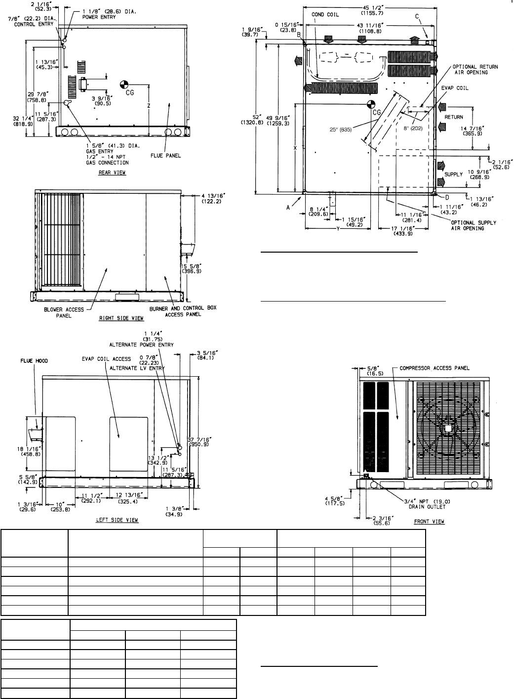
GENERAL
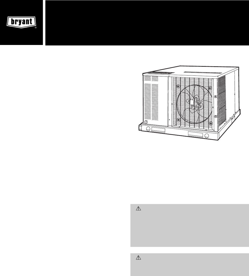
The 588A, 589Aunits (see Fig. 1) are fully self-contained, com-
bination Category I gas heating/electric cooling units de-
signed for outdoor installation. See Fig. 2-9 (pages 2-9) for
unit dimensions. All unit sizes have discharge openings for
both horizontal and downflow configurations, and are factory
shipped with all 4 duct openings covered. Units may be in-
stalled either on a rooftop or a ground-level cement slab. See
Fig. 10 for roof curb dimensions.
Fig. 1 — Unit 589A Shown With Optional Base Rail
installation, start-up
and service instructions
SINGLE PACKAGE GAS HEATING/
ELECTRIC COOLING UNITS
588A
Sizes 018-060
589A
Sizes 024-060
Cancels: II 588A-18-8 II 588A-18-9
9/15/98
REQ’D CLEARANCES FOR SERVICING. in. (mm)
Duct panel .............................0
Unit top ...........................36(914)
Side opposite ducts .....................36(914)
Compressor access .....................36(914)
(Except for NEC requirements)
REQ’D CLEARANCES TO COMBUSTIBLE MAT’L. in. (mm)
Maximum extension of overhangs ...............48(1219)
Unit top ...........................14(356)
Duct side of unit ........................2(51)
Side opposite ducts .....................14(356)
Bottom of unit ...........................0
Flue panel .........................36(914)
NEC REQ’D CLEARANCES. in. (mm)
Between units, control box side ................42(1067)
Unit and ungrounded surfaces, control box side .........36(914)
Unit and block or concrete walls and other grounded
surfaces, control box side ..................42(1067)
UNIT
588A ELECTRICAL
CHARACTERISTICS UNIT WEIGHT CORNER WEIGHT
(lb/kg) UNIT HEIGHT
(in./mm)
lbkgABCD E
018040 208/230-1-60 272 123 81/37 62/28 76/35 53/24 24.1/613
024040 208/230-1-60 303 138 97/44 43/20 123/56 40/18 24.1/613
024060 208/230-1-60 315 143 100/45 46/21 126/57 43/20 24.1/613
030040 208/230-1-60, 208/230-3-60 320 145 100/45 47/21 126/57 47/21 24.1/613
030060/080 208/230-1-60, 208/230-3-60 332 149 103/46 50/22 129/58 50/23 24.1/613
036060/080 208/230-1-60, 208/230-3-60, 460-3-60 336 153 86/39 76/35 111/50 63/29 24.1/613
036100/120 208/230-1-60, 208/230-3-60, 460-3-60 348 158 89/40 79/36 114/52 66/30 24.1/613
042060/080 208/230-1-60, 208/230-3-60, 460-3-60 375 170 95/43 86/39 119/54 75/34 28.1/714
042100/120 208/230-1-60, 208/230-3-60, 460-3-60 387 176 98/45 89/40 122/55 78/35 28.1/714
UNIT
588A F
in./mm G
in./mm CENTER OF GRAVITY in./mm
XYZ
018040
16
9
⁄
16
/420.7 18
15
⁄
16
/481.0
25.07/637 20.59/523
10.85/276
024040 27.07/688 23.35/593
024060 26.98/685 23.27/591
030040 26.71/678 23.46/596
030060/080 27.15/689 22.36/568
036060/080 27.50/698 22.48/571
036100/120 27.40/696 22.44/570
042060/080 20
9
⁄
16
/522.3 22
15
⁄
16
/582.6 27.01/686 22.44/570 12.7/321
042100/120 26.94/684 22.44/570
LEGEND
CG — Center of Gravity
COND — Condenser
LV — Low Voltage
MAT’L — Material
NEC — National Electrical Code
REQ’D — Required
NOTES:
1. Clearances must be maintained to prevent recirculation of air from outdoor-
fan discharge.
2. Adequate clearance around air openings into combustion chamber must
be provided.
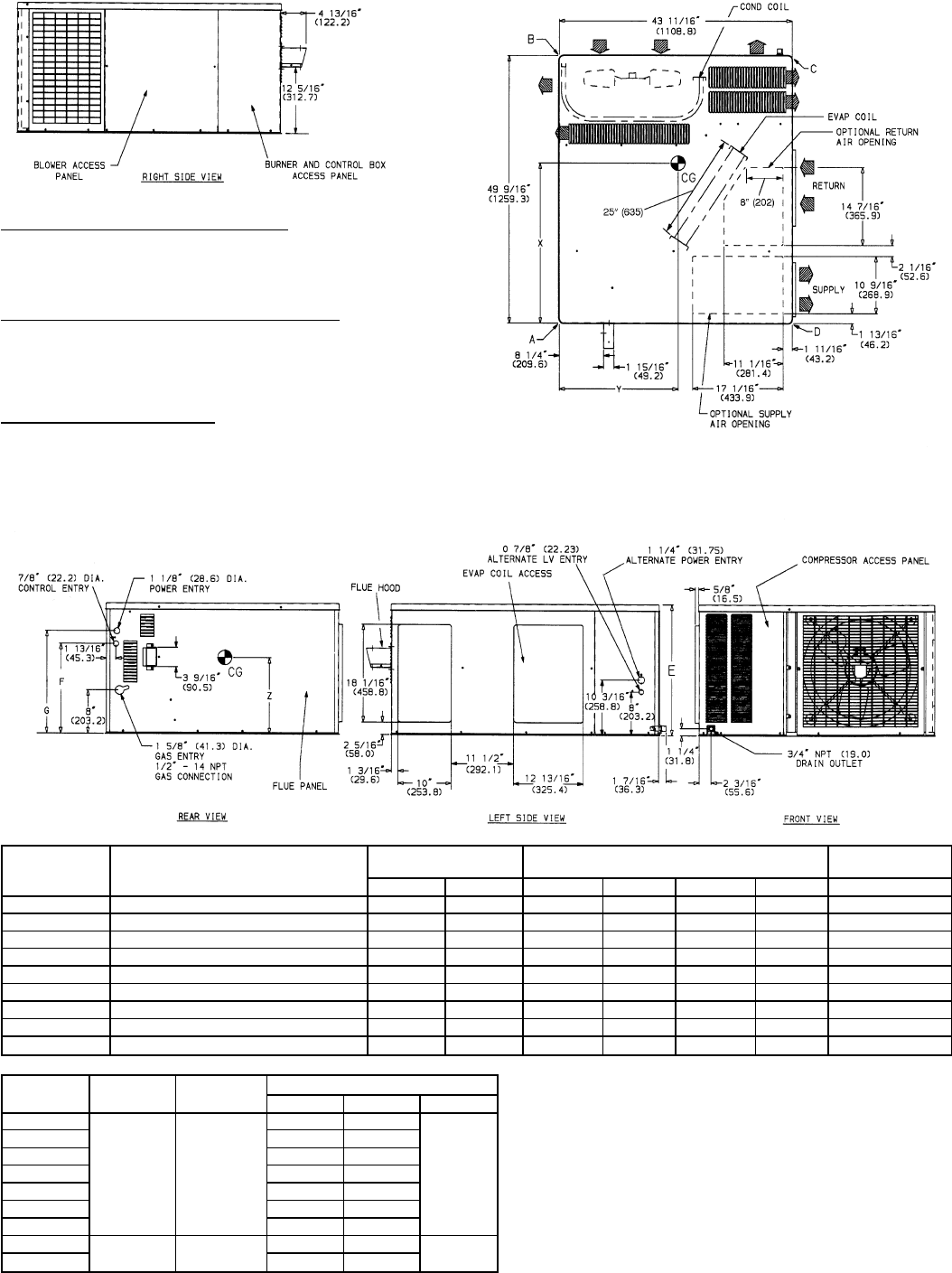
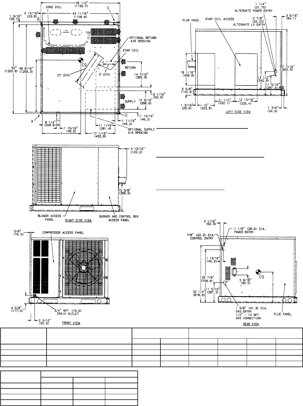
Fig. 2 — 588A018-042 Without Base Rail, Unit Dimensions
—2—
REQ’D CLEARANCES FOR SERVICING. in. (mm)
Duct panel .............................0
Unit top ...........................36(914)
Side opposite ducts .....................36(914)
Compressor access .....................36(914)
(Except for NEC requirements)
REQ’D CLEARANCES TO COMBUSTIBLE MAT’L. in. (mm)
Maximum extension of overhangs ...............48(1219)
Unit top ...........................14(356)
Duct side of unit ........................2(51)
Side opposite ducts .....................14(356)
Bottom of unit ...........................0
Flue panel .........................36(914)
NEC REQ’D CLEARANCES. in. (mm)
Between units, control box side ................42(1067)
Unit and ungrounded surfaces, control box side .........36(914)
Unit and block or concrete walls and other grounded
surfaces, control box side ..................42(1067)
UNIT
588A ELECTRICAL
CHARACTERISTICS UNIT WEIGHT CORNER WEIGHT
(lb/kg) UNIT HEIGHT
(in./mm)
lbkgABCD E
018040 208/230-1-60 296 135 87/40 68/31 82/37 59/27 27.4/697
024040 208/230-1-60 327 149 103/47 49/22 129/59 46/21 27.4/697
024060 208/230-1-60 339 155 106/48 52/24 132/60 49/22 27.4/697
030040 208/230-1-60, 208/230-3-60 344 157 106/48 53/24 132/60 53/24 27.4/697
030060/080 208/230-1-60, 208/230-3-60 356 162 102/46 71/32 123/56 60/27 27.4/697
036060/080 208/230-1-60, 208/230-3-60, 460-3-60 360 164 92/42 82/37 117/53 69/31 27.4/697
036100/120 208/230-1-60, 208/230-3-60, 460-3-60 372 169 95/43 85/39 120/55 72/33 27.4/697
042060/080 208/230-1-60, 208/230-3-60, 460-3-60 399 181 101/46 92/42 125/57 81/37 31.4/798
042100/120 208/230-1-60, 208/230-3-60, 460-3-60 411 187 104/47 95/43 128/58 84/38 31.4/798
UNIT
588A F
in./mm G
in./mm CENTER OF GRAVITY in./mm
XYZ
018040
19
7
⁄
8
/504.8 22
1
⁄
4
/565.4
25.04/636 22.72/577
13.16/334.3
024040 26.90/683.3 20.17/512.3
024060 26.82/681.2 20.22/513.6
030040 26.57/674.9 20.1 /509.3
030060/080 26.93/684 21.1 /535.4
036060/080 27.31/693.7 21.0 /532.6
036100/120 27.23/691.6 21.0 /533.1
042060/080 23
7
⁄
8
/606.4 26
1
⁄
4
/666.8 26.87/682.5 21.0 /533.1 14.96/380
042100/120 26.81/681 21.0 /533.7
LEGEND
CG — Center of Gravity
COND — Condenser
LV — Low Voltage
MAT’L — Material
NEC — National Electrical Code
REQ’D — Required
NOTES:
1. Clearances must be maintained to prevent recirculation of air from outdoor-
fan discharge.
2. Adequate clearance around air openings into combustion chamber must
be provided.
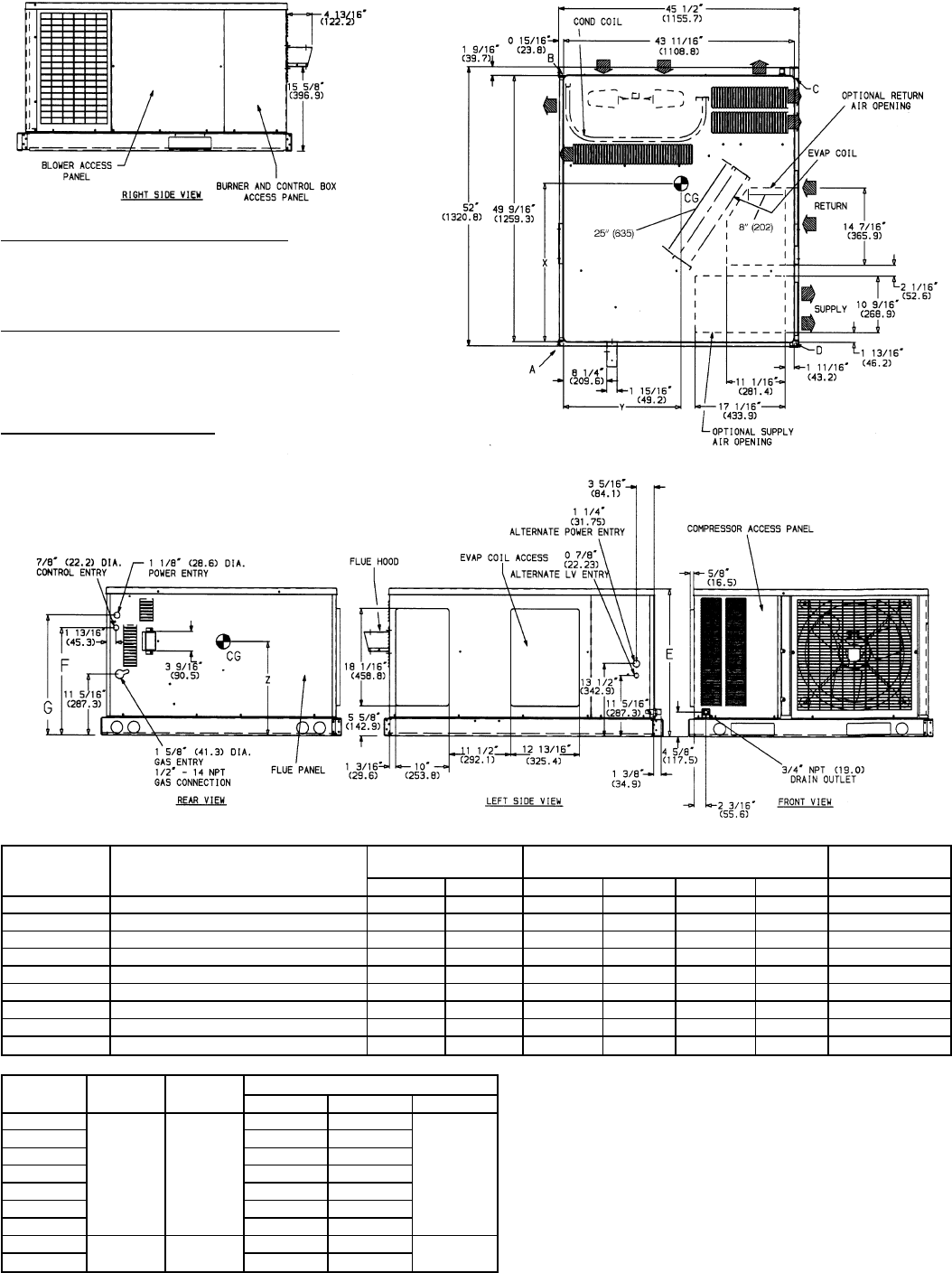
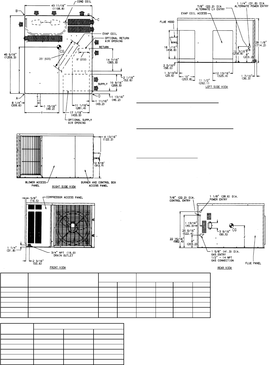
Fig. 3 — 588A018-042 With Optional Base Rail, Unit Dimensions
—3—
REQ’D CLEARANCES FOR SERVICING. in. (mm)
Duct panel .............................0
Unit top ...........................36(914)
Side opposite ducts .....................36(914)
Compressor access .....................36(914)
(Except for NEC requirements)
REQ’D CLEARANCES TO COMBUSTIBLE MAT’L. in. (mm)
Maximum extension of overhangs ...............48(1219)
Unit top ...........................14(356)
Duct side of unit ........................2(51)
Side opposite ducts .....................14(356)
Bottom of unit ...........................0
Flue panel .........................36(914)
NEC REQ’D CLEARANCES. in. (mm)
Between units, control box side ................42(1067)
Unit and ungrounded surfaces, control box side .........36(914)
Unit and block or concrete walls and other grounded
surfaces, control box side ..................42(1067)
UNIT
588A ELECTRICAL
CHARACTERISTICS UNIT WEIGHT CORNER WEIGHT
(lb/kg)
lbkgABCD
048080 208/230-1-60, 208/230-3-60, 460-3-60 414 188 107/49 83/38 158/72 66/30
048100/120/140 208/230-1-60, 208/230-3-60, 460-3-60 426 193 110/50 86/39 159/72 71/32
060080 208/230-1-60, 208/230-3-60, 460-3-60 453 206 117/53 93/42 167/76 76/35
060100/120/140 208/230-1-60, 208/230-3-60, 460-3-60 465 211 120/55 96/44 167/76 82/37
UNIT
588A CENTER OF GRAVITY (in./mm)
XYZ
048080 28.76/731 23.46/596 15.35/390
048100/120/140 28.42/722 23.42/595 15.35/390
060080 28.36/720 23.27/591 15.35/390
060100/120/140 27.95/710 23.23/590 15.35/390
LEGEND
CG — Center of Gravity
COND — Condenser
LV — Low Voltage
MAT’L — Material
NEC — National Electrical Code
REQ’D — Required
NOTES:
1. Clearances must be maintained to prevent recirculation of air from outdoor-
fan discharge.
2. Adequate clearance around air openings into combustion chamber must
be provided.
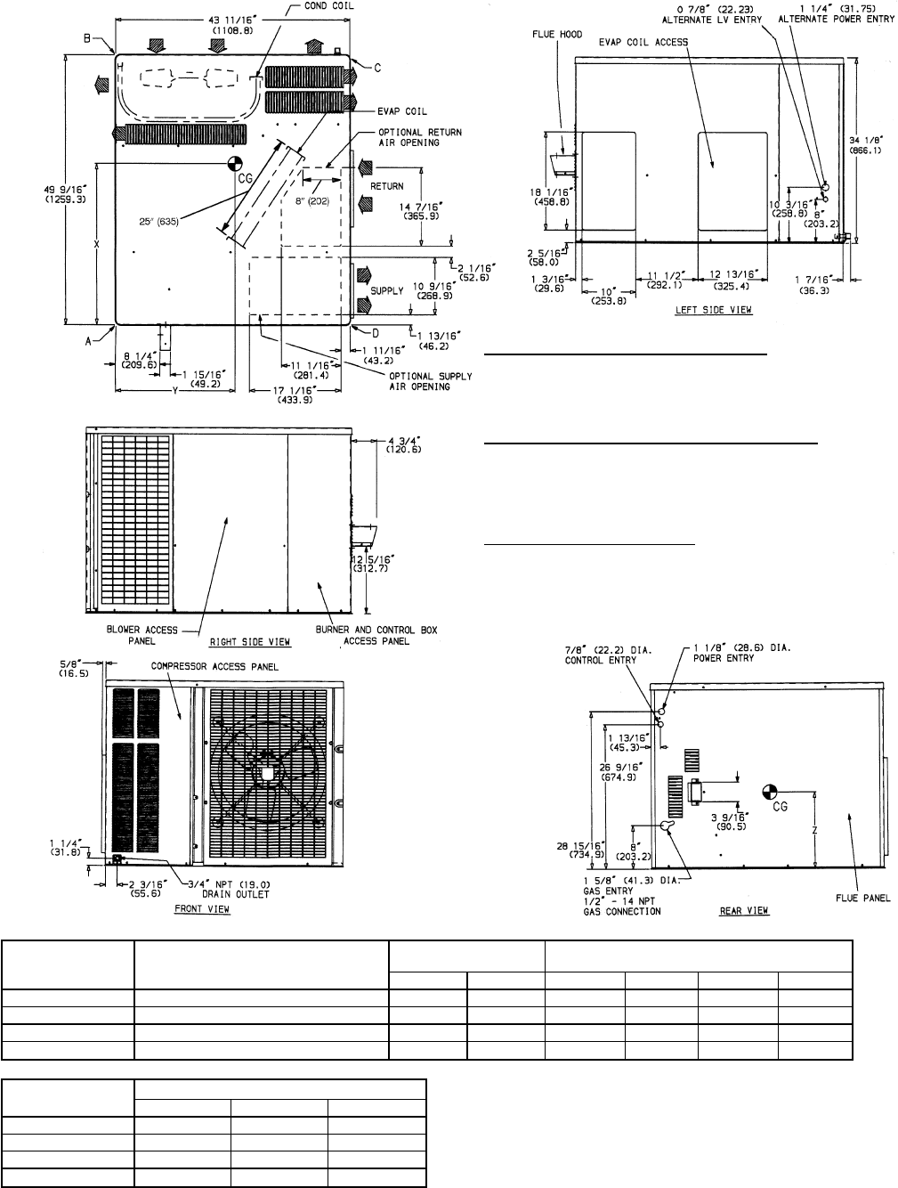
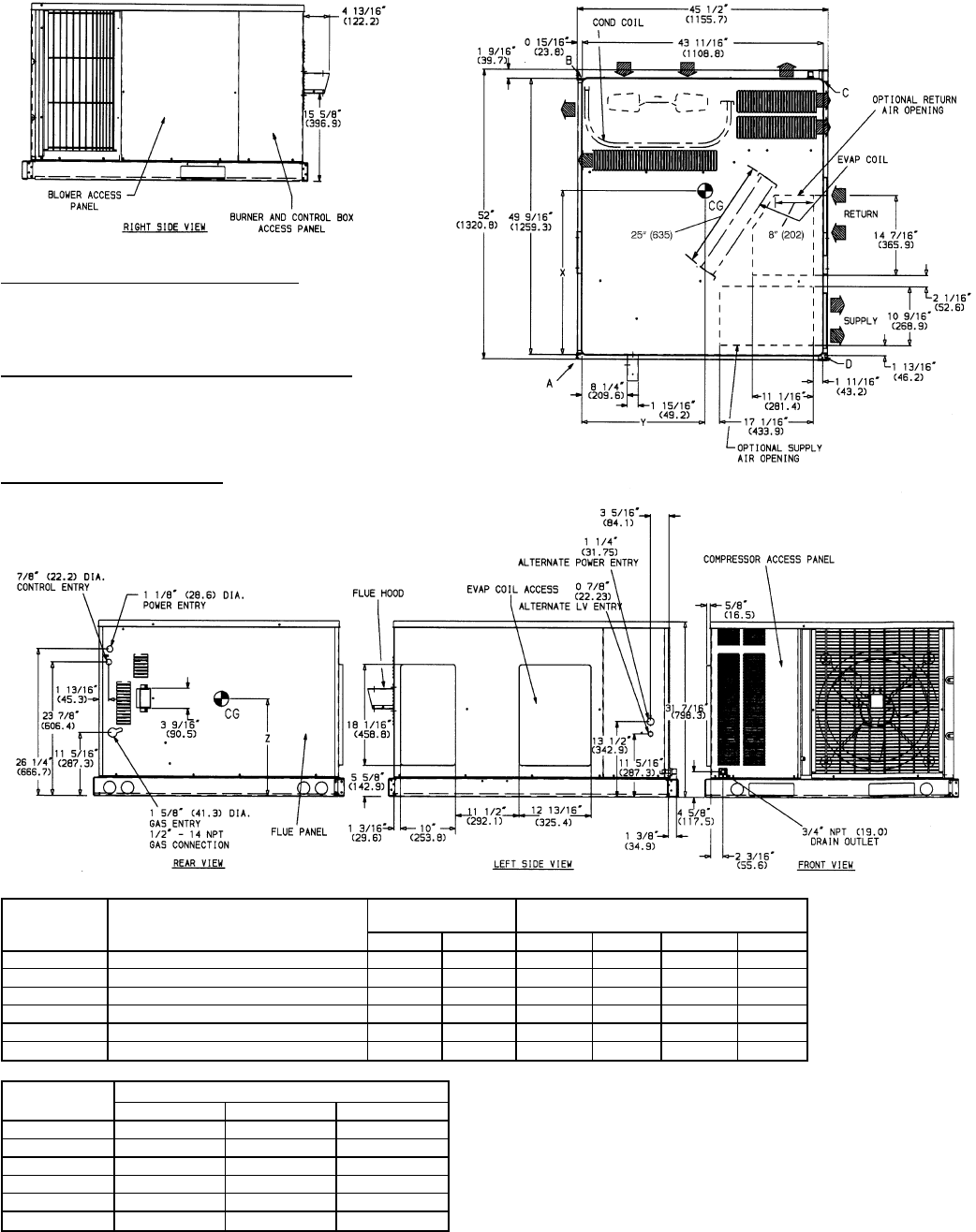
Fig. 4 — 588A048,060 Without Base Rail, Unit Dimensions
—4—
REQ’D CLEARANCES FOR SERVICING. in. (mm)
Duct panel .............................0
Unit top ...........................36(914)
Side opposite ducts .....................36(914)
Compressor access .....................36(914)
(Except for NEC requirements)
REQ’D CLEARANCES TO COMBUSTIBLE MAT’L. in. (mm)
Maximum extension of overhangs ...............48(1219)
Unit top ...........................14(356)
Duct side of unit ........................2(51)
Side opposite ducts .....................14(356)
Bottom of unit ...........................0
Flue panel .........................36(914)
NEC REQ’D CLEARANCES. in. (mm)
Between units, control box side ................42(1067)
Unit and ungrounded surfaces, control box side .........36(914)
Unit and block or concrete walls and other grounded
surfaces, control box side ..................42(1067)
UNIT
588A ELECTRICAL
CHARACTERISTICS UNIT WEIGHT CORNER WEIGHT
(lb/kg)
lb kg A B C D
048080 208/230-1-60, 208/230-3-60, 460-3-60 438 199 113/51 89/40 164/75 72/33
048100/120/140 208/230-1-60, 208/230-3-60, 460-3-60 450 205 116/53 92/42 165/75 77/35
060080 208/230-1-60, 208/230-3-60, 460-3-60 477 217 123/56 99/45 173/79 82/37
060100/120/140 208/230-1-60, 208/230-3-60, 460-3-60 489 222 126/57 102/46 173/79 88/40
UNIT
588A CENTER OF GRAVITY (in./mm)
XYZ
048080 28.54/724.9 20.00/508 17.66/448.6
048100/120/140 28.22/716.8 20.05/509.3 17.66/448.6
060080 28.18/715.6 20.19/512.8 17.66/448.6
060100/120/140 27.79/705.9 20.23/513.8 17.66/448.6
LEGEND
CG — Center of Gravity
COND — Condenser
LV — Low Voltage
MAT’L — Material
NEC — National Electrical Code
REQ’D — Required
NOTES:
1. Clearances must be maintained to prevent recirculation of air from outdoor-
fan discharge.
2. Adequate clearance around air openings into combustion chamber must
be provided.
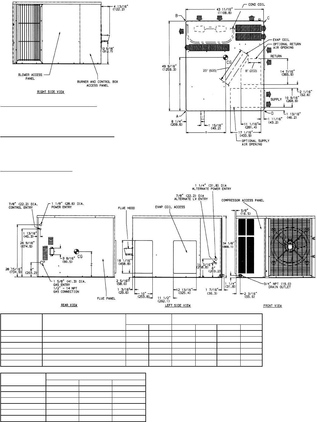
Fig. 5 — 588A048,060 With Optional Base Rail, Unit Dimensions
—5—
REQ’D CLEARANCES FOR SERVICING. in. (mm)
Duct panel .............................0
Unit top ...........................36(914)
Side opposite ducts .....................36(914)
Compressor access .....................36(914)
(Except for NEC requirements)
REQ’D CLEARANCES TO COMBUSTIBLE MAT’L. in. (mm)
Maximum extension of overhangs ...............48(1219)
Unit top ...........................14(356)
Duct side of unit ........................2(51)
Side opposite ducts .....................14(356)
Bottom of unit ...........................0
Flue panel .........................36(914)
NEC REQ’D CLEARANCES. in. (mm)
Between units, control box side ................42(1067)
Unit and ungrounded surfaces, control box side .........36(914)
Unit and block or concrete walls and other grounded
surfaces, control box side ..................42(1067)
UNIT
589A ELECTRICAL
CHARACTERISTICS UNIT WEIGHT CORNER WEIGHT
(lb/kg)
lb kg A B C D
024040 208/230-1-60 333 151 104/47 50/23 130/59 49/22
024060 208/230-1-60 345 157 107/49 53/24 133/60 52/24
030040 208/230-1-60 336 153 97/44 66/30 118/54 55/25
030060/080 208/230-1-60 348 158 100/45 69/31 121/55 58/26
036060/080 208/230-1-60, 208/230-3-60, 460-3-60 366 166 94/43 84/38 117/53 71/32
036100/120 208/230-1-60, 208/230-3-60, 460-3-60 378 172 97/44 87/40 120/55 74/34
UNIT
589A CENTER OF GRAVITY (in./mm)
XYZ
024040 26.71/678 20.06/510 12.65/321
024060 26.64/677 20.12/511 12.65/321
030040 27.06/687 21.05/535 12.65/321
030060/080 26.98/685 21.07/535 12.65/321
036060/080 27.14/689 21.10/536 12.65/321
036100/120 27.06/687 21.12/536 12.65/321
LEGEND
CG — Center of Gravity
COND — Condenser
LV — Low Voltage
MAT’L — Material
NEC — National Electrical Code
REQ’D — Required
NOTES:
1. Clearances must be maintained to prevent recirculation of air from outdoor-
fan discharge.
2. Adequate clearance around air openings into combustion chamber must
be provided.
Fig. 6 — 589A024-036 Without Base Rail, Unit Dimensions
—6—
REQ’D CLEARANCES FOR SERVICING. in. (mm)
Duct panel ...........................0
Unit top .........................36(914)
Side opposite ducts ....................36(914)
Compressor access ....................36(914)
(Except for NEC requirements)
REQ’D CLEARANCES TO COMBUSTIBLE MAT’L. in. (mm)
Maximum extension of overhangs .............48(1219)
Unit top .........................14(356)
Duct side of unit ......................2(51)
Side opposite ducts ....................14(356)
Bottom of unit .........................0
Flue panel ........................36(914)
NEC REQ’D CLEARANCES. in. (mm)
Between units, control box side ..............42(1067)
Unit and ungrounded surfaces, control box side .......36(914)
Unit and block or concrete walls and other grounded
surfaces, control box side ................42(1067)
UNIT
589A ELECTRICAL
CHARACTERISTICS UNIT WEIGHT CORNER WEIGHT
(lb/kg)
lbkgABCD
024040 208/230-1-60 357 163 110/50 56/25 136/62 55/25
024060 208/230-1-60 369 168 113/51 59/27 139/63 58/26
030040 208/230-1-60 360 164 103/47 72/33 124/56 61/28
030060/080 208/230-1-60 372 169 106/48 75/34 127/58 64/29
036060/080 208/230-1-60, 208/230-3-60, 460-3-60 390 177 100/45 90/41 123/56 77/35
036100/120 208/230-1-60, 208/230-3-60, 460-3-60 402 183 103/47 93/42 127/57 80/36
UNIT
589A CENTER OF GRAVITY (in./mm)
XYZ
024040 26.57/674.9 20.17/512.3 14.96/380.0
024060 26.51/673.3 20.22/513.6 14.96/380.0
030040 26.90/683.3 21.09/535.7 14.96/380.0
030060/080 26.83/681.5 21.11/536.2 14.96/380.0
036060/080 26.99/685.5 21.14/537.0 14.96/380.0
036100/120 26.92/683.8 21.14/537.0 14.96/380.0
LEGEND
CG — Center of Gravity
COND — Condenser
LV — Low Voltage
MAT’L — Material
NEC — National Electrical Code
REQ’D — Required
NOTES:
1. Clearances must be maintained to prevent recirculation of air from outdoor-
fan discharge.
2. Adequate clearance around air openings into combustion chamber must
be provided.
Fig. 7 — 589A024-036 With Optional Base Rail, Unit Dimensions
—7—
REQ’D CLEARANCES FOR SERVICING. in. (mm)
Duct panel .............................0
Unit top ...........................36(914)
Side opposite ducts .....................36(914)
Compressor access .....................36(914)
(Except for NEC requirements)
REQ’D CLEARANCES TO COMBUSTIBLE MAT’L. in. (mm)
Maximum extension of overhangs ...............48(1219)
Unit top ...........................14(356)
Duct side of unit ........................2(51)
Side opposite ducts .....................14(356)
Bottom of unit ...........................0
Flue panel .........................36(914)
NEC REQ’D CLEARANCES. in. (mm)
Between units, control box side ................42(1067)
Unit and ungrounded surfaces, control box side .........36(914)
Unit and block or concrete walls and other grounded
surfaces, control box side ..................42(1067)
UNIT
589A ELECTRICAL
CHARACTERISTICS UNIT WEIGHT CORNER WEIGHT
(lb/kg)
lbkgABCD
042060/080 208/230-1-60, 208/230-3-60, 460-3-60 391 178 100/45 91/41 120/55 80/36
042100/120 208/230-1-60, 208/230-3-60, 460-3-60 403 183 103/47 94/43 123/56 83/38
048080 208/230-1-60, 208/230-3-60, 460-3-60 422 192 109/50 85/39 158/72 70/32
048100/120/140 208/230-1-60, 208/230-3-60, 460-3-60 434 197 112/51 88/40 161/73 73/33
060080 208/230-1-60, 208/230-3-60 453 206 117/53 93/42 167/76 76/35
060100/120/140 208/230-1-60, 208/230-3-60 465 211 120/55 96/44 167/76 82/37
UNIT
589A CENTER OF GRAVITY (in./mm)
XYZ
042060/080 26.66/677 21.19/538 15.35/390
042100/120 26.61/676 21.21/539 15.35/390
048080 28.45/723 19.95/507 15.35/390
048100/120/140 28.35/720 19.99/508 15.35/390
060080 28.36/720 23.27/591 15.35/390
060100/120/140 27.95/710 23.23/590 15.35/390
LEGEND
CG — Center of Gravity
COND — Condenser
LV — Low Voltage
MAT’L — Material
NEC — National Electrical Code
REQ’D — Required
NOTES:
1. Clearances must be maintained to prevent recirculation of air from outdoor-
fan discharge.
2. Adequate clearance around air openings into combustion chamber must
be provided.
Fig. 8 — 589A042-060 Without Base Rail, Unit Dimensions
—8—
REQ’D CLEARANCES FOR SERVICING. in. (mm)
Duct panel .............................0
Unit top ...........................36(914)
Side opposite ducts .....................36(914)
Compressor access .....................36(914)
(Except for NEC requirements)
REQ’D CLEARANCES TO COMBUSTIBLE MAT’L. in. (mm)
Maximum extension of overhangs ...............48(1219)
Unit top ...........................14(356)
Duct side of unit ........................2(51)
Side opposite ducts .....................14(356)
Bottom of unit ...........................0
Flue panel .........................36(914)
LEGEND
CG — Center of Gravity
COND — Condenser
LV — Low Voltage
MAT’L — Material
NEC — National Electrical Code
REQ’D — Required
UNIT
589A ELECTRICAL
CHARACTERISTICS UNIT WEIGHT CORNER WEIGHT
(lb/kg)
lb kg A B C D
042060/080 208/230-1-60, 208/230-3-60, 460-3-60 415 189 106/48 97/44 126/57 86/39
042100/120 208/230-1-60, 208/230-3-60, 460-3-60 427 194 109/50 100/45 129/59 89/40
048080 208/230-1-60, 208/230-3-60, 460-3-60 446 293 115/52 91/41 164/75 76/35
048100/120/140 208/230-1-60, 208/230-3-60, 460-3-60 458 208 118/54 94/43 167/76 79/36
060080 208/230-1-60, 208/230-3-60 477 217 123/56 99/45 173/79 82/37
060100/120/140 208/230-1-60, 208/230-3-60 489 222 126/57 102/46 173/79 88/40
UNIT
589A CENTER OF GRAVITY (in./mm)
XYZ
042060/080 26.55/674.4 21.22/539.0 17.66/448.6
042100/120 26.50/673.0 21.24/539.6 17.66/448.6
048080 28.25/717.6 20.04/509.0 17.66/448.6
048100/120/140 28.16/715.3 20.08/510.0 17.66/448.6
060080 28.18/715.6 20.19/512.8 17.66/448.6
060100/120/140 27.79/705.9 20.23/513.8 17.66/448.6
NOTES:
1. Clearances must be maintained to prevent recirculation of air from outdoor-
fan discharge.
2. Adequate clearance around air openings into combustion chamber must be
provided.
NEC REQ’D CLEARANCES. in. (mm)
Between units, control box side ................42(1067)
Unit and ungrounded surfaces, control box side .........36(914)
Unit and block or concrete walls and other grounded
surfaces, control box side ..................42(1067)
Fig. 9 — 589A042-060 With Optional Base Rail, Unit Dimensions
—9—

RECEIVING AND INSTALLATION
I. STEP 1 — CHECK EQUIPMENT
A. Identify Unit
The unit model number and serial number are stamped on
unit identification plate. Check this information against ship-
ping papers and job data.
B. Inspect Shipment
Inspect for shipping damage while unit is still on shipping
pallet. If unit appears to be damaged or is torn loose from its
anchorage, have it examined by transportation inspectors be-
fore removal. Forward claim papers directly to transporta-
tion company. Manufacturer is not responsible for any dam-
age incurred in transit.
Check all items against shipping list. Immediately notify your
Bryant Heating and Cooling representative if any item is
missing.
To prevent loss or damage, leave all parts in original pack-
ages until installation.
II. STEP 2 — PROVIDE UNIT SUPPORT
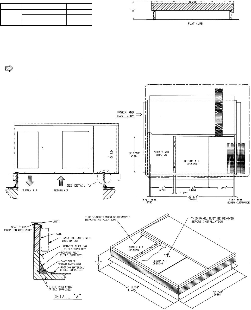
A. Roof Curb
Install accessory roof curb in accordance with instructions
shipped with curb. See Fig. 10 for roof curb dimensions. In-
stall insulation, cant strips, roofing, and flashing. Ductwork
must be attached to curb.
IMPORTANT: The gasketing of the unit to the roof curb is
critical for a watertight seal. Install gasketing material sup-
plied with the roof curb. Improperly applied gasketing can
also result in air leaks and poor unit performance.
Curb should be level to within
1
⁄
4
inch. This is necessary for
unit drain to function properly. Refer to accessory roof curb
installation instructions for additional information as
required.
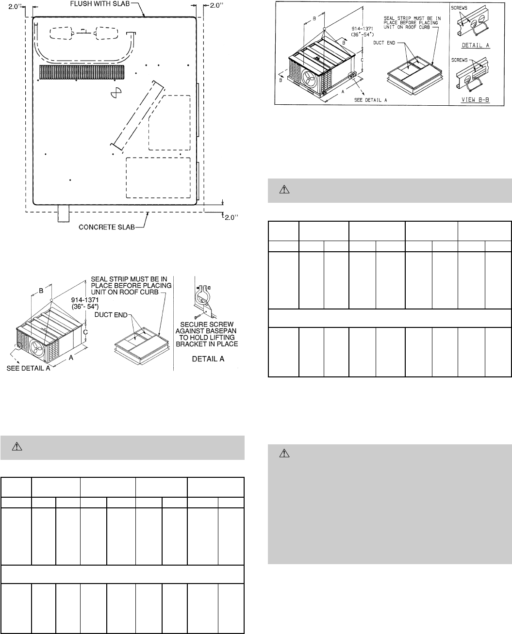
B. Slab Mount
Place the unit on a solid, level concrete pad that is a mini-
mum of 4 in. thick with 2 in. above grade. The slab should be
flush on the front of the unit (to allow condensate drain in-
stallation) and should extend 2 in. on the three remaining
sides of the unit. See Fig. 11. Install a 6-in. gravel apron in
front of condenser-air inlets to prevent obstruction of airflow
by grass or shrubs. Do not secure the unit to the slab except
when required by local codes.
C. Flush Mount
Place side of unit with duct panel flush against transition.
On units with optional base rails, the skirt on duct-panel side
of unit can be removed to allow unit to be mounted flush against
transitions that extend below basepan of unit. To remove skirt,
remove 4 screws holding skirt to base rail. Then, remove skirt.
To remove wood support under unit (with base rail only), loosen
4 screws above rigging holes and slide assembly out through
rectangular hole.
III. STEP 3 — FIELD FABRICATE DUCTWORK
Secure all ducts to roof curb and building structure on verti-
cal discharge units. Do not connect ductwork to unit. For hori-
zontal applications, unit is provided with flanges on the hori-
zontal openings.All ductwork should be secured to the flanges.
Insulate and weatherproof all external ductwork, joints, and
roof openings with counter flashing and mastic in accordance
with applicable codes.
Ducts passing through an unconditioned space must be in-
sulated and covered with a vapor barrier.
If a plenum return is used on a vertical unit, the return should
be ducted through the roof deck to comply with applicable
fire codes.
Aminimum clearance is not required around ductwork. Cabi-
net return-air static shall not exceed −.25 in. wg.
IV. STEP 4 — PROVIDE CLEARANCES
The required minimum operating and service clearances are
shown in Fig. 2-9.Adequate combustion, ventilation, and con-
denser air must be provided, in accordance with section 5.3,
Air for Combustion and Ventilation, of the National Fuel Gas
CodeANSI Z223.1 (in Canada, sections 7.2, 7.3 or 7.4 or Can/
CGA [Canadian Gas Association] B149 Installation Codes),
or applicable provisions of local building code.
CAUTION: Do not restrict condenser airflow. An air
restriction at either the outdoor-air inlet or the fan dis-
charge can be detrimental to compressor life.
The condenser fan pushes air through the condenser coil and
discharges it through the bank of louvers in the top cover,
the decorative grille on the right side of the unit, and the com-
pressor access panel. Be sure that the fan discharge does not
recirculate to the condenser coil. Do not locate the unit in ei-
ther a corner or under an overhead obstruction. The mini-
mum clearance under a partial overhang (such as a normal
house overhang) is 48-in. above the unit top. The maximum
horizontal extension of a partial overhang must not exceed
48 inches.
Do not place the unit where water, ice, or snow from an over-
hang or roof will damage or flood the unit. Do not install the
unit on carpeting, tile, or other combustible materials. The
unit may be installed on wood flooring or on Class A, B, or C
roof covering materials.
V. STEP 5 — RIG AND PLACE UNIT
CAUTION: When installing the unit on a rooftop, be
sure the roof will support the additional weight. Refer
to Fig. 2-9 for corner weight information.
Use spreader bars or crate top when rigging the unit. The
units must be rigged for lifting as shown in Fig. 12 and 13.
Refer to Tables 1 and 2 for operating weight and to Fig. 2-9
for corner weights. Use extreme caution to prevent damage
when moving the unit. Unit must remain in an upright posi-
tion during all rigging and moving operations. The unit must
be level for proper condensate drainage; therefore, the ground-
level pad or accessory roof curb must be level before setting
the unit in place. When a field-fabricated support is used, be
sure that the support is level and properly supports the unit.
—10—
PART NUMBER ‘‘A’’
FLAT
CURB
CPRFCURB001A00 89[203]
CPRFCURB002A00 119[279]
CPRFCURB003A00 149[356]
NOTES:
1. Roof curb must be set up for unit being installed.
2. Seal strip must be applied as required for unit being installed.
3. Dimensions in [ ] are in millimeters.
4. Roof curb is made of 16 gage steel.
5. Attach ductwork to curb (flanges of duct rest on curb).
6. Service clearance 4 ft on each side.
7. Direction of airflow.
8. Insulated panels: 1-in. thick fiberglass 1 lb density.
Fig. 10 — Roof Curb Dimensions
—11—
A. Units Without Base Rail
If accessory rigging brackets are to be used for rigging, in-
stall them as follows:
WARNING: Secure screws and paint protectors sol-
idly against unit basepan to hold lifting brackets in
position.
Never use lifting brackets when the temperature is be-
low −10 F.
Never exceed 200 lbs per bracket of lifting force.
Never use lifting brackets for lifting other models of air-
conditioning units.
Lifting point should be directly over the unit center of
gravity.
1. Position brackets as close to the corners of unit as pos-
sible. Be sure brackets are well outside of center of grav-
ity. (See Fig. 2, 4, 6, 8, and 12.).
2. Position paint protectors and foam strips between screws
and painted surface of unit. Tighten screws until they
make contact with the paint protectors.
3. Secure device or hook of sufficient strength to hole in
bracket as shown in detail ‘‘A’’ of Fig. 12.
4. If wood top is available, use it for a spreader bar to pre-
vent straps from damaging unit. If wood top is not avail-
able, use spreader bars of sufficient length.
Fig. 11 — Slab Mounting Details
NOTICE TO RIGGERS
Hook rigging shackles through holes in lifting brackets, as shown in De-
tail ‘‘A.’’ Lifting brackets to be centered around the unit center of gravity.
Use wooden top skid when rigging, to prevent rigging straps from dam-
aging unit.
CAUTION: All panels must be in place when rigging.
UNIT
588A MAX
WEIGHT ABC
Size lb kg in. mm in. mm in. mm
018 332 150
49.4 1255
24.3 618 24.85 631
024 375 170 22.4 570 24.85 631
030 384 174 22.3 565 24.85 631
036 408 185 22.0 559 24.85 631
042 447 203 22.5 571 28.85 733
048 486 220 21.0 533 34.85 885
060 525 238 21.5 545 34.85 885
UNIT
589A
024 405 184
49.4 1255
22.8 579 28.9 733
030 408 185 22.4 569 28.9 733
036 438 199 22.4 569 28.9 733
042 463 210 22.8 579 34.9 885
048 494 224 21.1 536 34.9 885
060 525 238 21.5 545 34.9 885
Fig. 12 — Suggested Rigging for Units Without
Base Rail
NOTICE TO RIGGERS
Hook rigging shackles through holes in lifting brackets, as shown in De-
tail ‘‘A.’’ Lifting brackets to be centered around the unit center of gravity.
Use wood top skid when rigging, to prevent rigging straps from damag-
ing unit. Remove 4 screws to slide wood support through rectangular
hole in rail.
CAUTION: All panels must be in place when rigging.
UNIT
588A MAX
WEIGHT ABC
Size lb kg in. mm in. mm in. mm
018 320 145
49.4 1255
24.4 619 28.2 715
024 363 165 22.6 574 28.2 715
030 380 172 22.5 571 28.2 715
036 396 180 22.2 563 28.2 715
042 435 197 22.6 574 32.2 816
048 474 215 21.2 538 38.2 969
060 513 233 21.6 549 38.2 969
UNIT
589A
024 393 178
49.4 1255
22.9 582 32.2 816
030 396 180 22.6 574 32.2 816
036 426 193 22.5 571 32.2 816
042 451 205 22.9 582 38.2 969
048 482 219 21.3 540 38.2 969
060 513 233 21.6 549 38.2 969
Fig. 13 — Suggested Rigging for Units With
Optional Base Rail
—12—
B. Units With Optional Base Rail
Lifting holes are provided in optional base rail as shown in
Fig. 13. Operating weights are shown in Tables 1 and 2. Re-
fer to rigging instructions on unit.
Protective wood support must be removed from unit before
unit is mounted to curb. Remove 4 screws that secure sup-
port above rigging holes in rails. Slide support out through
rectangular hole in rail. See Fig. 13.
VI. STEP 6 — CONNECT CONDENSATE DRAIN
NOTE: When installing condensate drain connection be sure
to comply with local codes and restrictions.
Model 588A, 589A disposes of condensate water through a
3
⁄
4
in. NPT fitting which exits through the compressor access panel.
See Fig. 2-9 for location.
Condensate water can be drained directly onto the roof in roof-
top installations (where permitted) or onto a gravel apron in
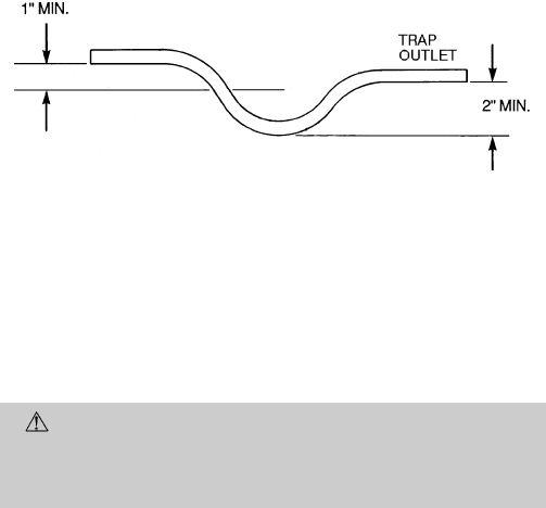
ground-level installations. Install a field-supplied conden-
sate trap at end of condensate connection to ensure proper
drainage. Make sure that the outlet of the trap is at least
1 in. lower than the drain-pan condensate connection to pre-
vent the pan from overflowing. See Fig. 14. Prime the trap
with water. When using a gravel apron, make sure it slopes
away from the unit.
If the installation requires draining the condensate water away
from the unit, install a 2-in. trap at the condensate connec-
tion to ensure proper drainage. See Fig. 14. Make sure that
the outlet of the trap is at least 1 in. lower than the drain-
pan condensate connection to prevent the pan from overflow-
ing. Prime the trap with water. Connect a drain tube using a
minimum of
3
⁄
4
-in. PVC or
3
⁄
4
-in. copper pipe (all field-
supplied) at the outlet end of the 2-in. trap. Do not undersize
the tube. Pitch the drain tube downward at a slope of at least
one in. for every 10 ft of horizontal run. Be sure to check the
drain tube for leaks.
VII. STEP 7 — INSTALL FLUE HOOD
The flue hood assembly is shipped screwed to the control box
in the burner compartment. Remove the burner access panel
to locate the assembly.
For units being installed in California Air Quality Manage-
ment Districts which require NO
x
emissions of 40 nanograms/
joule or less, kit CRLOWNOX001A00 must be installed.
CAUTION: The venting system is designed to en-
sure proper venting. The flue hood assembly must be
installed as indicated in this section of the unit instal-
lation instructions.
Install the flue hood as follows:
1. This installation must conform with local building codes
and with the National Fuel Gas Code (NFGC), Ameri-
can National Standards Institute (ANSI) Z223.1 (in
Canada, CAN/CGA B149.1, and B149.2) or NFPA (Na-
tional Fire Protection Association) latest revision. Refer
to Provincial and local plumbing or wastewater codes
and other applicable local codes.
2. Remove from shipping location. Place vent cap assem-
bly over flue panel. Orient screw holes in vent cap with
holes in the flue panel.
3. Secure flue hood to flue panel by inserting a single screw
on the right side, the left side, and the top of the hood.
VIII. STEP 8 — INSTALL GAS PIPING
The gas supply pipe enters the unit through the access hole
provided. The gas connection to the unit is made to the
1
⁄
2
-in.
FPT gas inlet on the manual shutoff or gas valve.
Install a gas supply line that runs to the heating section. Re-
fer to Table 3 and the NFGC for gas pipe sizing. Do not use
cast-iron pipe. It is recommended that a black iron pipe is
used. Check the local utility for recommendations concern-
ing existing lines. Size gas supply piping for 0.5 in. wg maxi-
mum pressure drop. Never use pipe smaller than the
1
⁄
2
-in.
FPT gas inlet on the unit gas valve.
For natural gas applications, the gas pressure at unit gas con-
nection must not be less than 4.0 in. wg or greater than
13 in. wg while the unit is operating. For propane applica-
tions, the gas pressure must not be less than 4.0 in. wg or
greater than 13 in. wg at the unit connection.
An
1
⁄
8
-in. NPT plugged tapping accessible for test gage con-
nection must be installed immediately upstream of the gas
supply connection to the furnace.
When installing the gas supply line, observe local codes per-
taining to gas pipe installations. Refer to the NFGC ANSI
Z223.1-1988 NFPAlatest edition (in Canada, CAN/CGAB149.1,
(2)-M86). In the absence of local building codes, adhere to the
following pertinent recommendations:
1. Avoid low spots in long runs of pipe. Grade all pipe
1
⁄
4
inch in every 15 ft to prevent traps. Grade all hori-
zontal runs downward to risers. Use risers to connect to
heating section and to meter.
2. Protect all segments of piping system against physical
and thermal damage. Support all piping with appropri-
ate straps, hangers, etc. Use a minimum of one hanger
every 6 ft. For pipe sizes larger than
1
⁄
2
in., follow rec-
ommendations of national codes.
3. Apply joint compound (pipe dope) sparingly and only to
male threads of joint when making pipe connections. Use
only pipe dope that is resistant to action of liquefied
petroleum gases as specified by local and/or national codes.
Never use Teflon tape.
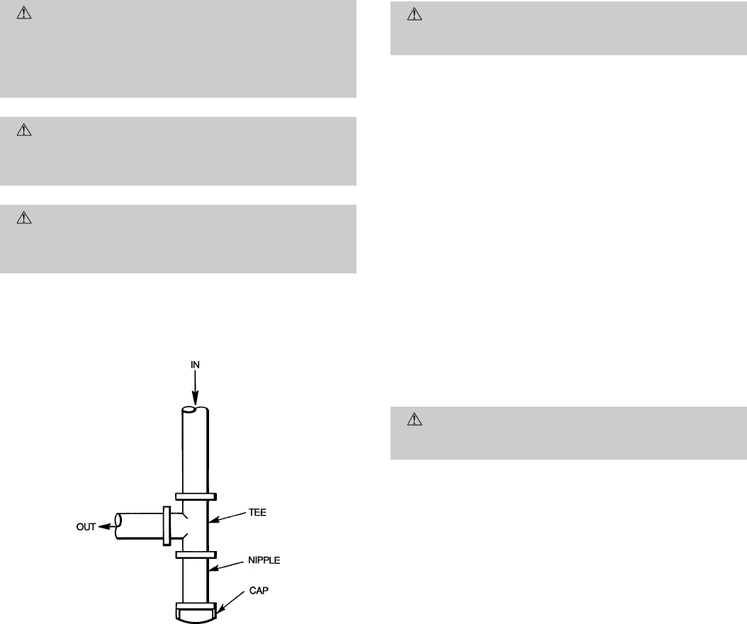
4. Install sediment trap in riser leading to heating section
per Fig. 15. This drip leg functions as a trap for dirt and
condensate.
5. Install an accessible, external, manual main shutoff valve
in gas supply pipe within 6 ft of heating section.
6. Install ground-joint union close to heating section be-
tween unit manual shutoff and external manual main
shutoff valve.
7. Pressure-test all gas piping in accordance with local and
national plumbing and gas codes before connecting pip-
ing to unit.
NOTE: Pressure test the gas supply system after the gas sup-
ply piping is connected to the gas valve. The supply piping
must be disconnected from the gas valve during the testing
of the piping systems when test pressure is in excess of
0.5 psig. Pressure test the gas supply piping system at pres-
sures equal to or less than 0.5 psig. The unit heating section
must be isolated from the gas piping system by closing the
external main manual shutoff valve and slightly opening the
ground-joint union.
Fig. 14 — Condensate Trap
—13—
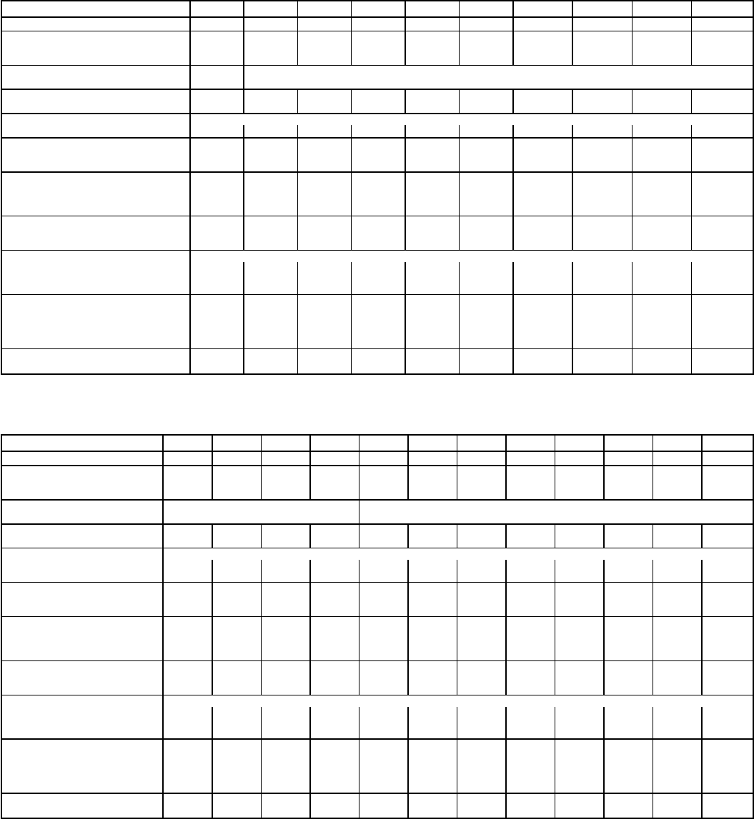
Table 1 — Physical Data — Unit 588A
UNIT SIZE 588A 018040 024040 024060 030040 030060 030080 036060 036080 036100 036120
NOMINAL CAPACITY (ton) 1
1
⁄
2
222
1
⁄
2
2
1
⁄
2
2
1
⁄
2
3333
OPERATING WEIGHT (lb)
Without Base Rail 272 303 315 320 332 332 336 336 348 348
With Optional Base Rail 296 327 339 344 356 356 360 360 372 372
COMPRESSORS Rotary Reciprocating
Quantity 11
REFRIGERANT (R-22)
Charge (lb) 2.60 2.75 2.75 3.40 3.40 3.40 4.30 4.30 4.30 4.30
REFRIGERANT METERING DEVICE Acutrol™ Device
Orifice ID (in.) .030 .030 .030 .030 .030 .030 .032 .032 .032 .032
CONDENSER COIL
Rows...Fins/in. 1...17 1...17 1...17 2...17 2...17 2...17 2...17 2...17 2...17 2...17
Face Area (sq ft) 5.95 5.95 5.95 5.95 5.95 5.95 5.95 5.95 5.95 5.95
CONDENSER FAN
Nominal Cfm 1700 1700 1700 1900 1900 1900 1900 1900 1900 1900
Diameter (in.) 18 18 18 18 18 18 18 18 18 18
Motor Hp (Rpm)
1
⁄
8
(850)
1
⁄
8
(850)
1
⁄
8
(850)
1
⁄
8
(850)
1
⁄
8
(850)
1
⁄
8
(850)
1
⁄
4
(1050)
1
⁄
4
(1050)
1
⁄
4
(1050)
1
⁄
4
(1050)
EVAPORATOR COIL
Rows Fins/in. 3...15 3...15 3...15 3...15 3...15 3...15 3...15 3...15 3...15 3...15
Face Area (sq ft) 1.83 2.29 2.29 2.29 2.29 2.29 3.06 3.06 3.06 3.06
EVAPORATOR FAN Direct Drive
Nominal Airflow (Cfm) 600 800 800 1000 1000 1000 1200 1200 1200 1200
Size (in.) 10x10 10x10 10x10 10x10 10x10 10x10 10x10 10x10 10x10 10x10
Motor Hp
1
⁄
41
⁄
41
⁄
41
⁄
41
⁄
41
⁄
41
⁄
21
⁄
21
⁄
21
⁄
2
FURNACE SECTION*
Burner Orifice (Qty...drill size)
Natural Gas 1...32 1...32 2...40 1...32 2...40 2...32 2...40 2...32 2...30 3...32
Burner Orifice (Qty...drill size)
Propane Gas 1...41 1...41 2...47 1...41 2...47 2...42 2...47 2...42 2...40 3...42
RETURN-AIR FILTERS (in.)†
Throwaway 20x20 20x20 20x20 20x24 20x24 20x24 20x24 20x24 20x24 20x24
UNIT SIZE 588A 042060 042080 042100 042120 048080 048100 048120 048140 060080 060100 060120 060140
NOMINAL CAPACITY (ton) 3
1
⁄
2
3
1
⁄
2
3
1
⁄
2
3
1
⁄
2
44445555
OPERATING WEIGHT (lb)
Without Base Rail 375 375 387 387 414 426 426 426 453 465 465 465
With Optional Base Rail 399 399 411 411 438 450 450 450 477 489 489 489
COMPRESSORS Reciprocating Hermetic Scroll
Quantity 11
REFRIGERANT (R-22)
Charge (lb) 5.20 5.20 5.20 5.20 6.50 6.50 6.50 6.50 7.00 7.00 7.00 7.00
REFRIGERANT METERING Acutrol Device
DEVICE
Orifice ID (in.) .034 .034 .034 .034 .030 .030 .030 .030 .030 .030 .030 .030
CONDENSER COIL
Rows...Fins/in. 2...17 2...17 2...17 2...17 2...17 2...17 2...17 2...17 2...17 2...17 2...17 2...17
Face Area (sq ft) 7.04 7.04 7.04 7.04 8.67 8.67 8.67 8.67 8.67 8.67 8.67 8.67
CONDENSER FAN
Nominal Cfm 1900 1900 1900 1900 2400 2400 2400 2400 2400 2400 2400 2400
Diameter (in.) 18 18 18 18 20 20 20 20 20 20 20 20
Motor Hp (Rpm)
1
⁄
4
(1050)
1
⁄
4
(1050)
1
⁄
4
(1050)
1
⁄
4
(1050)
1
⁄
3
(1050)
1
⁄
3
(1050)
1
⁄
3
(1050)
1
⁄
3
(1050)
1
⁄
3
(1050)
1
⁄
3
(1050)
1
⁄
3
(1050)
1
⁄
3
(1050)
EVAPORATOR COIL
Rows Fins/in. 3...15 3...15 3...15 3...15 3...15 3...15 3...15 3...15 4...15 4...15 4...15 4...15
Face Area (sq ft) 3.33 3.33 3.33 3.33 4.44 4.44 4.44 4.44 4.44 4.44 4.44 4.44
EVAPORATOR FAN Direct Drive
Nominal Airflow (Cfm) 1400 1400 1400 1400 1600 1600 1600 1600 1995 1995 1995 1995
Size (in.) 10x10 10x10 10x10 10x10 10x10 10x10 10x10 10x10 10x11 10x11 10x11 10x11
Motor Hp
3
⁄
43
⁄
43
⁄
43
⁄
43
⁄
43
⁄
43
⁄
43
⁄
4
1111
FURNACE SECTION*
Burner Orifice (Qty...drill size)
Natural Gas 2...40 2...32 2...30 3...32 2...32 2...30 3...32 3...31 2...32 2...30 3...32 3...31
Burner Orifice (Qty...drill size)
Propane Gas 2...47 2...42 2...40 3...42 2...42 2...40 3...42 3...40 3...42 2...40 3...42 3...40
RETURN-AIR FILTERS (in.)†
Throwaway 24x24 24x24 24x24 24x24 24x30 24x30 24x30 24x30 24x30 24x30 24x30 24x30
*Based on altitude of 0-2000 feet.
†Required filter sizes shown are based on the larger of the ARI (Air Conditioning & Refrigeration Institute) rated
cooling airflow or the heating airflow at a velocity of 300 ft/min for throwaway type or 450 ft/min for high-capacity
type. For non-standard air filters, air filter pressure drop must not exceed 0.08 in. wg.
—14—
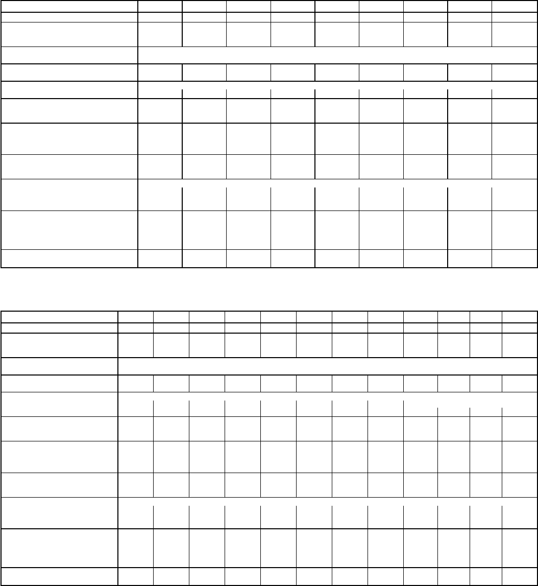
Table 2 — Physical Data — Unit 589A
UNIT SIZE 589A 024040 024060 030040 030060 030080 036060 036080 036100 036120
NOMINAL CAPACITY (ton) 222
1
⁄
2
2
1
⁄
2
2
1
⁄
2
3333
OPERATING WEIGHT (lb)
Without Base Rail 333 345 336 348 348 366 366 378 378
With Optional Base Rail 357 369 360 372 372 390 390 402 402
COMPRESSORS Scroll
Quantity 1
REFRIGERANT (R-22)
Charge (lb) 3.9 3.9 4.5 4.5 4.5 5.4 5.4 5.4 5.4
REFRIGERANT METERING DEVICE Acutrol™ Device
Orifice ID (in.) .034 .034 .030 .030 .030 .032 .032 .032 .032
CONDENSER COIL
Rows...Fins/in. 2...17 2...17 2...17 2...17 2...17 2...17 2...17 2...17 2...17
Face Area (sq ft) 7.0 7.0 7.0 7.0 7.0 7.0 7.0 7.0 7.0
CONDENSER FAN
Nominal Cfm 2200 2200 2200 2200 2200 2200 2200 2200 2200
Diameter (in.) 20 20 20 20 20 20 20 20 20
Motor Hp (Rpm)
1
⁄
4
(1100)
1
⁄
4
(1100)
1
⁄
4
(1100)
1
⁄
4
(1100)
1
⁄
4
(1100)
1
⁄
4
(1100)
1
⁄
4
(1100)
1
⁄
4
(1100)
1
⁄
4
(1100)
EVAPORATOR COIL
Rows Fins/in. 2...15 2...15 3...15 3...15 3...15 4...15 4...15 4...15 4...15
Face Area (sq ft) 3.6 3.6 2.7 2.7 2.7 3.6 3.6 3.6 3.6
EVAPORATOR FAN* Direct Drive
Nominal Airflow (Cfm) 800 800 1000 1000 1000 1200 1200 1200 1200
Size (in.) 10x10 10x10 10x10 10x10 10x10 10x10 10x10 10x10 10x10
Motor Hp
1
⁄
41
⁄
41
⁄
41
⁄
41
⁄
41
⁄
21
⁄
21
⁄
21
⁄
2
FURNACE SECTION†
Burner Orifice (Qty...drill size)
Natural Gas 1...32 2...41 1...32 2...40 2...32 2...40 2...32 2...30 3...32
Burner Orifice (Qty...drill size)
Propane Gas 1...41 2...47 1...41 2...47 2...42 2...47 2...42 2...40 3...42
RETURN-AIR FILTERS (in.)**
Disposable 24x24 24x24 24x24 24x24 24x24 24x24 24x24 24x24 24x24
UNIT SIZE 589A 042060 042080 042100 042120 048080 048100 048120 048140 060080 060100 060120 060140
NOMINAL CAPACITY (ton) 3
1
⁄
2
3
1
⁄
2
3
1
⁄
2
3
1
⁄
2
44445555
OPERATING WEIGHT (lb)
Without Base Rail 391 391 403 403 422 434 434 434 453 465 465 465
With Optional Base Rail 415 415 427 427 446 458 458 458 477 489 489 489
COMPRESSORS Scroll
Quantity 1
REFRIGERANT (R-22)
Charge (lb) 5.7 5.7 5.7 5.7 5.8 5.8 5.8 5.8 7.00 7.00 7.00 7.00
REFRIGERANT METERING Acutrol Device
DEVICE
Orifice ID (in.) .034 .034 .034 .034 .034 .034 .034 .034 .030 .030 .030 .030
CONDENSER COIL
Rows...Fins/in. 2...17 2...17 2...17 2...17 2...17 2...17 2...17 2...17 2...17 2...17 2...17 2...17
Face Area (sq ft) 8.7 8.7 8.7 8.7 8.7 8.7 8.7 8.7 8.67 8.67 8.67 8.67
CONDENSER FAN
Nominal Cfm 2400 2400 2400 2400 2400 2400 2400 2400 2400 2400 2400 2400
Diameter (in.) 20 20 20 20 20 20 20 20 20 20 20 20
Motor Hp (Rpm)
1
⁄
4
(1100)
1
⁄
4
(1100)
1
⁄
4
(1100)
1
⁄
4
(1100)
1
⁄
4
(1100)
1
⁄
4
(1100)
1
⁄
4
(1100)
1
⁄
4
(1100)
1
⁄
3
(1050)
1
⁄
3
(1050)
1
⁄
3
(1050)
1
⁄
3
(1050)
EVAPORATOR COIL
Rows Fins/in. 3...15 3...15 3...15 3...15 4...15 4...15 4...15 4...15 4...15 4...15 4...15 4...15
Face Area (sq ft) 4.4 4.4 4.4 4.4 4.4 4.4 4.4 4.4 4.44 4.44 4.44 4.44
EVAPORATOR FAN* Direct Drive
Nominal Airflow (Cfm) 1400 1400 1400 1400 1600 1600 1600 1600 1995 1995 1995 1995
Size (in.) 10x10 10x10 10x10 10x10 10x10 10x10 10x10 10x10 10x11 10x11 10x11 10x11
Motor Hp
3
⁄
43
⁄
43
⁄
43
⁄
43
⁄
43
⁄
43
⁄
43
⁄
4
1111
FURNACE SECTION†
Burner Orifice (Qty...drill size)
Natural Gas 2...40 2...32 2...30 3...32 2...32 2...30 3...32 3...31 2...32 2...30 3...32 3...31
Burner Orifice (Qty...drill size)
Propane Gas 2...47 2...42 2...40 3...42 2...42 2...40 3...42 3...40 3...42 2...40 3...42 3...40
RETURN-AIR FILTERS (in.)**
Disposable 24x30 24x30 24x30 24x30 24x30 24x30 24x30 24x30 24x30 24x30 24x30 24x30
*Size 048 evaporator fan is equipped with a 460-v or integrated control motor (ICM). Size 060 evaporator fan is
equipped with an ICM only. The ICM provides variable speed.
†Based on an altitude of 0-2000 feet.
**Required filter sizes shown are based on the ARI (Air Conditioning & Refrigeration Institute) rated heating airflow
at a velocity of 300 ft/min for throwaway type or 450 ft/min for high-capacity type. For non-standard air filters, air
filter pressure drop must not exceed 0.08 in. wg.
—15—
(Text continued from page 13)
CAUTION: Unstable operation may occur when the
gas valve and manifold assembly are forced out of po-
sition while connecting improperly-routed rigid gas pip-
ing to the gas valve. Use a backup wrench when mak-
ing connection to avoid strain on, or distortion of, the
gas control piping.
CAUTION: If a flexible conductor is required or al-
lowed by the authority having jurisdiction, black iron
pipe shall be installed at the gas valve and shall ex-
tend a minimum of 2 in. outside the unit casing.
WARNING: Never use a match or other open flame
when checking for gas leaks. Never purge gas line into
combustion chamber. Failure to follow this warning could
result in an explosion causing personal injury or death.
8. Check for gas leaks at the field-installed and factory-
installed gas lines after all piping connections have been
completed. Use soap-and-water solution (or method speci-
fied by local codes and/or regulations).
IX. STEP 9 — INSTALL DUCT CONNECTIONS
The unit has duct flanges on the supply- and return-air open-
ings on the side and bottom of the unit. See Fig. 2-9 for con-
nection sizes and locations.
A. Configuring Units for Downflow (Vertical) Discharge
WARNING: Before performing service or mainte-
nance operations on the system, turn off main power to
unit or electrical shock could result.
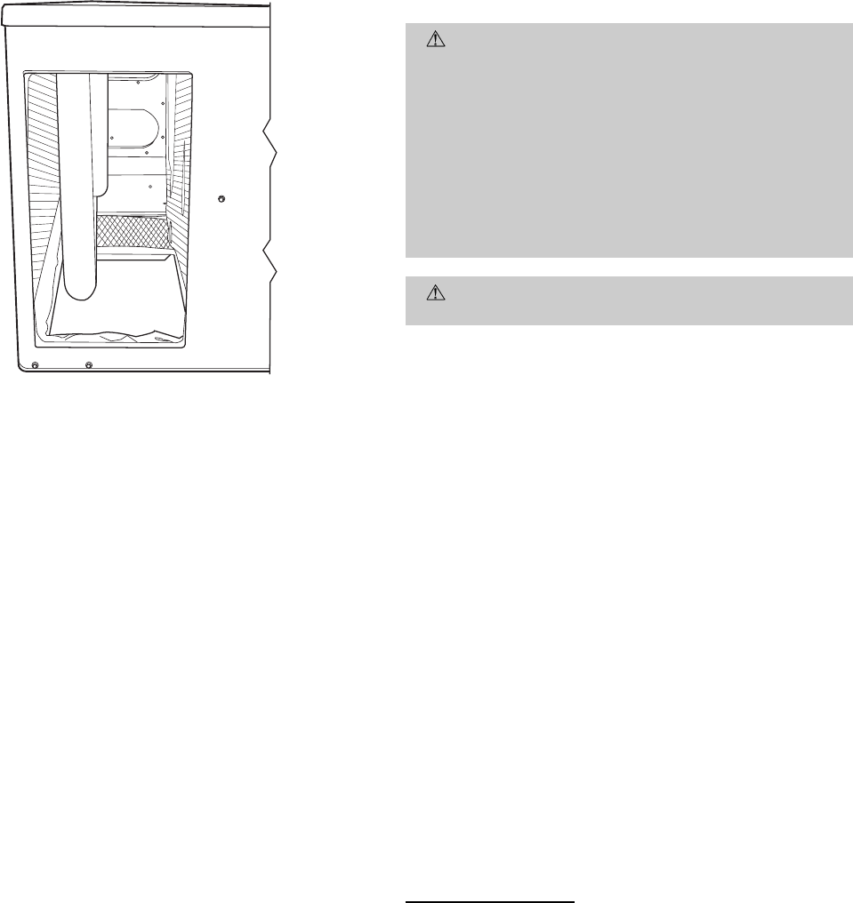
1. Open all electrical disconnects before starting any serv-
ice work.
2. Remove return duct cover located on duct panel.
Figure 16 shows duct cover removed. Save duct cover
and screws.
3. Locate lances in basepan insulation that are placed over
the perimeter of the vertical duct opening cover
(Fig. 17).
4. Using a straight edge and sharp knife, cut and remove
the insulation around the perimeter of the cover. Re-
move and save 5 screws securing the cover to the base-
pan and slide out the cover. Discard the cover (Fig. 18).
5. Remove supply duct cover located on duct panel.
Figure 16 shows duct cover removed. Save duct cover
and screws.
6. Remove and discard 2 screws which secure vertical dis-
charge opening cover to basepan (Fig. 19). Slide cover
forward to disengage, then tilt and remove cover through
vertical discharge opening in bottom of unit. Discard
duct cover (Fig. 20).
CAUTION: Collect ALL screws that were removed.
Do not leave screws on rooftop as permanent damage
to the roof may occur.
7. If unit ductwork is to be attached to vertical opening
flanges on the unit basepan (jackstand applications only),
do so at this time.
8. It is recommended that the basepan insulation around
the perimeter of the vertical return-air opening be se-
cured to the basepan with aluminum tape. Applicable
local codes may require aluminum tape to prevent ex-
posed fiberglass.
9. Cover both horizontal duct openings with the duct cov-
ers from Steps 2 and 5. Make sure opening is air- and
watertight.
10. After completing unit conversion, perform all safety
checks and power up unit.
NOTE: The design and installation of the duct system must
be in accordance with the standards of the NFPA for instal-
lation of nonresidence-type air conditioning and ventilating
systems, NFPA 90A or residence-type, NFPA 90B; and/or lo-
cal codes and residence-type, NFPA 90B; and/or local codes
and ordinances.
Fig. 15 — Sediment Trap
—16—
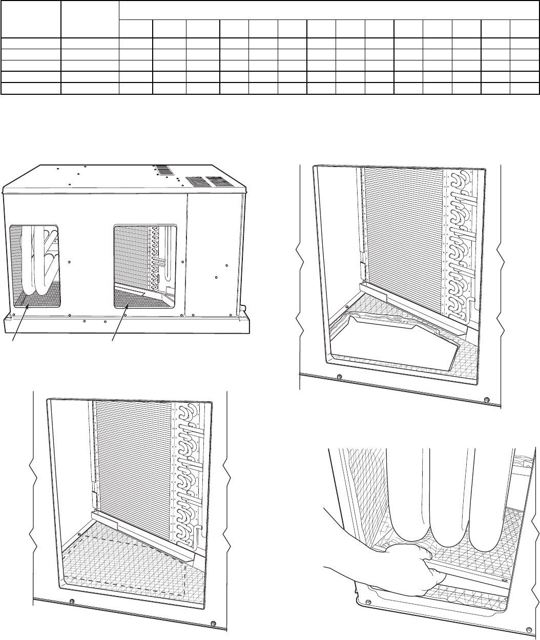
Table 3 — Maximum Gas Flow Capacity*
NOMINAL
IRON PIPE,
SIZE
(in.)
INTERNAL
DIAMETER
(in.)
LENGTH OF PIPE, FT†
10 20 30 40 50 60 70 80 90 100 125 150 175 200
1
⁄
2
.622 175 120 97 82 73 66 61 57 53 50 44 40 — —
3
⁄
4
.824 360 250 200 170 151 138 125 118 110 103 93 84 77 72
11.049 680 465 375 320 285 260 240 220 205 195 175 160 145 135
1
1
⁄
4
1.380 1400 950 770 600 580 530 490 460 430 400 360 325 300 280
1
1
⁄
2
1.610 2100 1460 1180 990 900 810 750 690 650 620 550 500 460 430
*Capacity of pipe in cu ft of gas per hr for gas pressure of 0.5 psig or less. Pressure drop of 0.5-in. wg (based on
a 0.60 specific gravity gas). Refer to Table C-4, National Fire Protection Association NFPA 54.
†This length includes an ordinary number of fittings.
SUPPLY DUCT OPENING RETURN DUCT OPENING
Fig. 16 — Supply and Return Duct Openings
Fig. 17 — Lance Location for Vertical Duct
Opening Cover
Fig. 18 — Vertical Duct Cover Removed
Fig. 19 — Removal of Vertical Discharge
Opening Cover
—17—
Adhere to the following criteria when selecting, sizing,
and installing the duct system:
1. Units are shipped with all 4 duct openings covered. Re-
move appropriate panels for intended installation.
2. Select and size ductwork, supply-air registers, and
return-air grilles according to American Society of
Heating, Refrigeration and Air Conditioning Engineers
(ASHRAE) recommendations.
3. Use flexible transition between rigid ductwork and unit
to prevent transmission of vibration. The transition may
be screwed or bolted to duct flanges. Use suitable gas-
kets to ensure weathertight and airtight seal.
4. All units must have field-supplied filters or accessory fil-
ter rack installed in the return-air side of the unit. Rec-
ommended sizes for filters are shown in Tables 1 and 2.
5. Size all ductwork for maximum required airflow (either
heating or cooling) for unit being installed.Avoid abrupt
duct size increases or decreases or performance may be
affected.
6. Adequately insulate and weatherproof all ductwork
located outdoors. Insulate ducts passing through uncon-
ditioned space, and use vapor barrier in accordance with
latest issue of Sheet Metal and Air Conditioning
Contractors NationalAssociation (SMACNA) andAir Con-
ditioning Contractors of America (ACCA) minimum in-
stallation standards for heating and air conditioning
systems. Secure all ducts to building structure.
7. Flash, weatherproof, and vibration-isolate all openings
in building structure in accordance with local codes and
good building practices.
X. STEP 10 — INSTALL ELECTRICAL CONNECTIONS
WARNING: The unit cabinet must have an uninter-
rupted, unbroken electrical ground to minimize the pos-
sibility of personal injury if an electrical fault should
occur. This ground may consist of an electrical wire con-
nected to the unit ground lug in the control compart-
ment, or conduit approved for electrical ground when
installed in accordance with NEC (National Electrical
Code) ANSI/NFPA (latest edition) (in Canada, Cana-
dian Electrical Code CSA [Canadian Standards Asso-
ciation] C22.1) and local electrical codes. Do not use gas
piping as an electrical ground. Failure to adhere to this
warning could result in personal injury or death.
CAUTION: Failure to follow these precautions could
result in damage to the unit being installed:
1. Make all electrical connections in accordance with NEC
ANSI/NFPA(latest edition) and local electrical codes gov-
erning such wiring. In Canada, all electrical connec-
tions must be in accordance with CSA standard C22.1
Canadian Electrical Code Part 1 and applicable local codes.
Refer to unit wiring diagram.
2. Use only copper conductor for connections between field-
supplied electrical disconnect switch and unit. DO NOT
USE ALUMINUM WIRE.
3. Be sure that high-voltage power to unit is within oper-
ating voltage range indicated on unit rating plate.
4. Do not damage internal components when drilling through
any panel to mount electrical hardware, conduit, etc. On
3-phase units, ensure phases are balanced within 2%.
Consult local power company for correction of improper
voltage and/or phase imbalance.
A. High-Voltage Connections
The unit must have a separate electrical service with a field-
supplied, waterproof, disconnect switch mounted at, or within
sight from, the unit. Refer to the unit rating plate for maxi-
mum fuse/circuit breaker size and minimum circuit amps (am-
pacity) for wire sizing. See Tables 4A and 4B for electrical
data.
The field-supplied disconnect switch box may be mounted on
the unit over the high-voltage inlet hole when the
standard power and low-voltage entry points are used. See
Fig. 2-9 for acceptable location.
Standard Power Entry
Proceed as follows to complete the high-voltage connections
to the unit:
1. Connect ground lead to chassis ground connection when
using separate ground wire.
2. Run high-voltage leads into unit control box.
3. Locate black and yellow wires connected to line side of
contactor.
4. Cut wires at partition where they exit control box.
5. Strip back leads and connect to high voltage leads. On
3-phase units, blue wire is provided stripped back and
ready to connect to high voltage lead. See unit wiring
label and Fig. 21.
Fig. 20 — Vertical Discharge Cover Removed
—18—
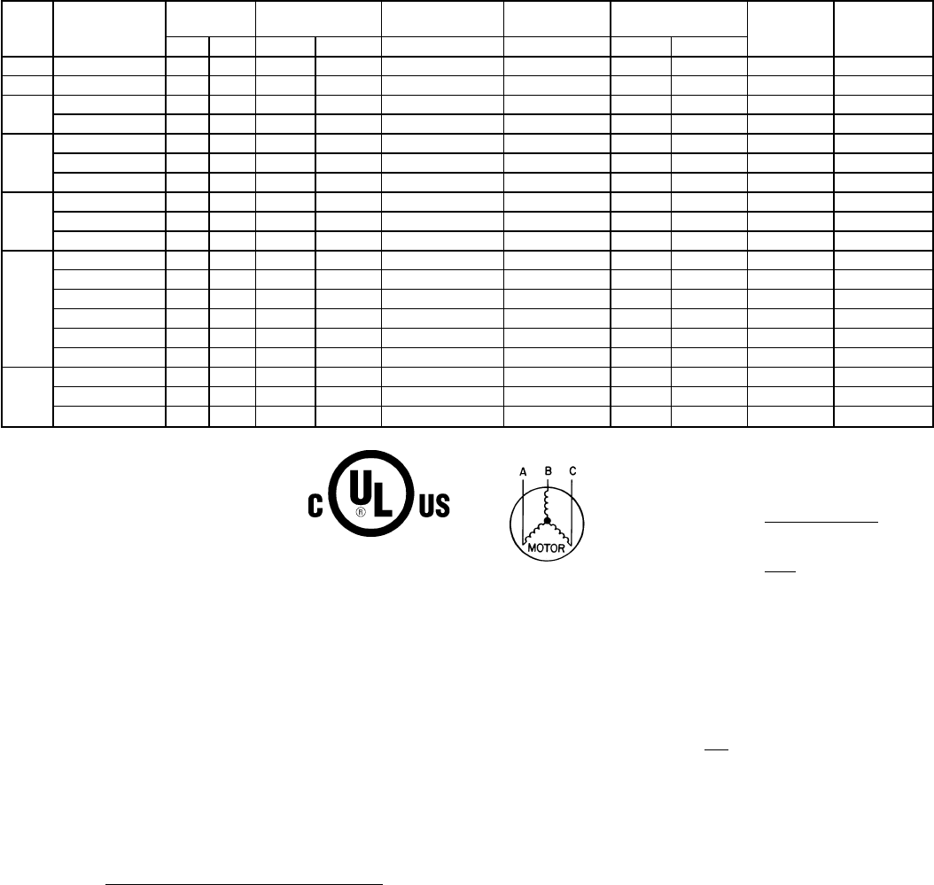
Table 4A — Electrical Data — Unit 588A
UNIT
SIZE
588A V-PH-Hz VOLTAGE
RANGE COMPRESSOR OUTDOOR-FAN
MOTOR INDOOR-FAN
MOTOR POWER SUPPLY AWG60C
MIN WIRE
SIZE
MAX WIRE
LENGTH (ft)
Min Max RLA LRA FLA FLA MCA MOCP*
018 208/230-1-60 187 253 8.3 45.0 0.7 1.8 12.9 15 14 75
024 208/230-1-60 187 253 12.4 61.0 0.7 2.0 18.2 30 12 80
030 208/230-1-60 187 253 14.4 82.0 1.4 2.3 21.4 30 10 100
208/230-3-60 187 253 9.4 66.0 1.4 2.0 15.1 25 12 80
036
208/230-1-60 187 253 18.0 96.0 1.4 2.8 26.7 40 10 90
208/230-3-60 187 253 11.7 75.0 1.4 2.8 18.8 30 12 65
460-3-60 414 506 5.6 40.0 0.8 1.4 9.2 10 14 100
042
208/230-1-60 187 253 20.4 104.0 1.4 4.0 30.9 50 8 100
208/230-3-60 187 253 14.0 91.0 1.4 4.0 22.9 35 10 85
460-3-60 414 506 6.4 42.0 0.8 2.0 10.8 15 14 100
048
208/230-1-60† 187 253 21.8 124.0 2.1 5.0 40.1 60 8 100
208/230-1-60** 187 253 26.4 129.0 2.1 5.0 40.1 60 6 100
208/230-3-60† 187 253 12.8 93.0 2.1 5.0 25.9 40 10 75
208/230-3-60** 187 253 15.0 99.0 2.1 5.0 25.9 40 10 75
460-3-60† 414 506 6.4 46.5 1.1 2.3 13.7 20 14 100
460-3-60** 414 506 8.2 50.0 1.1 2.3 13.7 20 14 100
060
208/230-1-60 187 253 32.1 169.0 2.1 6.8 49.0 60 6 100
208/230-3-60 187 253 19.3 123.0 2.1 6.8 33.0 50 8 90
460-3-60 414 506 10.0 62.0 1.1 3.2 16.8 25 12 100
LEGEND
AWG — American Wire Gage
FLA — Full Load Amps
HACR — Heating, Air Conditioning and
Refrigeration
LRA — Locked Rotor Amps
MCA — Minimum Circuit Amps
MOCP — Maximum Overcurrent Protection
RLA — Rated Load Amps
*Fuse or HACR Breaker.
† Carrier Scroll Compressor.
**Copeland Scroll Compressor.
NOTES:
1. In compliance with NEC (National Electrical Code) requirements for
multimotor and combination load equipment (refer to NEC
Articles 430 and 440), the overcurrent protective device for the unit
shall be fuse or HACR breaker. The CGA (Canadian Gas Associa-
tion) units may be fuse or circuit breaker.
2. Minimum wire size is based on 60 C copper wire. If other than
60 C wire is used, or if length exceeds wire length in table, deter-
mine size from NEC.
3. Unbalanced 3-Phase Supply Voltage
Never operate a motor where a phase imbalance in supply voltage is
greater than 2%.
Use the following formula to determine the percent-
age of voltage imbalance.
% Voltage imbalance
max voltage deviation from average voltage
= 100 x average voltage
Example: Supply voltage is 460-3-60.
AB = 452 v
BC = 464 v
AC = 455 v
452 1464 1455
Average Voltage = 3
1371
=3
= 457
Determine maximum deviation from average voltage.
(AB) 457 − 452=5v
(BC) 464 − 457=7v
(AC) 457 − 455=2v
Maximum deviation is 7 v.
Determine percent of voltage imbalance.
7
% Voltage Imbalance = 100 x 457
= 1.53%
This amount of phase imbalance is satisfactory as it is below the maxi-
mum allowable 2%.
IMPORTANT: If the supply voltage phase imbalance is more than 2%,
contact your local electric utility company immediately.
—19—
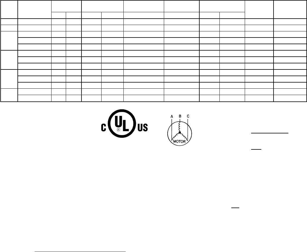
Table 4B — Electrical Data — Unit 589A
UNIT
SIZE
589A V-PH-Hz VOLTAGE
RANGE COMPRESSOR OUTDOOR-FAN
MOTOR INDOOR-FAN
MOTOR POWER SUPPLY AWG60C
MIN WIRE
SIZE
MAX WIRE
LENGTH (ft)
Min Max RLA LRA FLA FLA MCA MOCP*
024 208/230-1-60 187 253 12.9 62.5 1.4 2.0 19.5 30 12 75
030 208/230-1-60 187 253 15.0 76.0 1.4 2.6 22.8 30 10 100
036
208/230-1-60 187 253 16.7 95.0 1.4 2.8 25.1 30 10 95
208/230-3-60 187 253 10.9 75.0 1.4 2.8 17.8 25 12 70
460-3-60 414 506 5.4 40.0 0.8 1.4 9.0 10 14 100
042
208/230-1-60 187 253 20.0 104.0 1.4 3.1 29.5 45 10 80
208/230-3-60 187 253 13.9 88.0 1.4 3.1 21.9 30 10 60
460-3-60 414 506 6.8 44.0 0.8 1.6 10.9 15 14 100
048
208/230-1-60 187 253 26.4 129.0 1.4 7.2 41.6 60 6 100
208/230-3-60 187 253 15.0 99.0 1.4 7.2 27.4 40 10 70
460-3-60 414 506 8.2 49.5 0.8 2.3 13.4 20 14 100
060 208/230-1-60 187 253 32.1 169.0 2.1 7.2 49.4 60 6 100
208/230-3-60 187 253 19.3 123.0 2.1 7.2 33.4 50 8 90
LEGEND
AWG — American Wire Gage
FLA — Full Load Amps
HACR — Heating, Air Conditioning and
Refrigeration
LRA — Locked Rotor Amps
MCA — Minimum Circuit Amps
MOCP — Maximum Overcurrent Protection
RLA — Rated Load Amps
*Fuse or HACR Breaker.
† Carrier Scroll Compressor.
**Copeland Scroll Compressor.
NOTES:
1. In compliance with NEC (National Electrical Code) requirements for
multimotor and combination load equipment (refer to NEC
Articles 430 and 440), the overcurrent protective device for the unit
shall be fuse or HACR breaker. The CGA (Canadian Gas Associa-
tion) units may be fuse or circuit breaker.
2. Minimum wire size is based on 60 C copper wire. If other than
60 C wire is used, or if length exceeds wire length in table, deter-
mine size from NEC.
3. Unbalanced 3-Phase Supply Voltage
Never operate a motor where a phase imbalance in supply voltage is
greater than 2%.
Use the following formula to determine the percent-
age of voltage imbalance.
% Voltage imbalance
max voltage deviation from average voltage
= 100 x average voltage
Example: Supply voltage is 460-3-60.
AB = 452 v
BC = 464 v
AC = 455 v
452 1464 1455
Average Voltage = 3
1371
=3
= 457
Determine maximum deviation from average voltage.
(AB) 457 − 452=5v
(BC) 464 − 457=7v
(AC) 457 − 455=2v
Maximum deviation is 7 v.
Determine percent of voltage imbalance.
7
% Voltage Imbalance = 100 x 457
= 1.53%
This amount of phase imbalance is satisfactory as it is below the maxi-
mum allowable 2%.
IMPORTANT: If the supply voltage phase imbalance is more than 2%,
contact your local electric utility company immediately.
—20—
Alternate Power Entry
1. Remove knockouts in fixed compressor panel located on
duct panel side of unit.
2. Route high-voltage leads into high-voltage terminal box.
3. Connect ground wire to green-yellow wire using field-
supplied splice.
4. Connect power wires to unit high-voltage leads.
5. On 3-phase units, locate blue wire projecting from com-
pressor junction box. Cut wire at partition and route into
high-voltage junction box through grommet in back of
junction box.
6. On 3-phase units, strip back blue lead and connect to
third leg of the power wires.
B. Special Procedures for 208-V Operation
WARNING: Make sure that the gas supply then the
power supply to the unit is switched OFF before mak-
ing any wiring changes. Electrical shock can cause per-
sonal injury or death.
1. Disconnect the orange transformer-primary lead from
the contactor. See unit wiring label.
2. Remove the tape and wirenut from the terminal on the
end of the red transformer-primary lead.
3. Save the wirenut.
4. Connect the red lead to the contactor terminal from which
the orange lead was disconnected.
5. Using the wirenut removed from the red lead, insulate
the loose terminal on the orange lead.
6. Wrap the cover with electrical tape so that the metal
terminal cannot be seen.
C. Control Voltage Connections; Non-Integrated Control
Motor (Non-ICM) Units
Locate the room thermostat on an inside wall in the space to
be conditioned, where it will not be subjected to either a cool-
ing or heating source or direct exposure to sunlight. Mount
the thermostat 4 to 5 ft above the floor.
NOTE: Do not use any type of power-stealing thermostat. Unit
control problems may result.
Use no. 18 American Wire Gage (AWG) color-coded, insu-
lated (35 C minimum) wires to make the control voltage con-
nections between the thermostat and the unit. If the thermo-
stat is located more than 100 ft from the unit (as measured
along the control voltage wires), use no. 16 AWG color-coded,
insulated (35 C minimum) wires.
Standard Connection
Remove knockout hole located in the flue panel adjacent to
the control access panel. See Fig. 2-9. Remove the rubber grom-
met from the installer’s packet (included with unit) and in-
stall grommet in the knockout opening. Provide a drip loop
before running wire through panel.
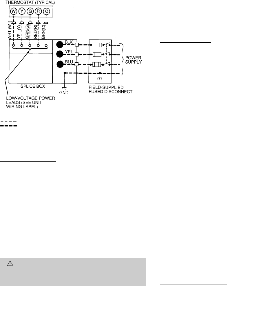
Run the low-voltage leads from the thermostat, through the
inlet hole, and into unit low-voltage splice box.
Locate five 18-gage wires leaving control box. These low-
voltage connection leads can be identified by the colors red,
green, yellow, brown, and white. (See Fig. 21.) Ensure the leads
are long enough to be routed into the low-voltage splice box
(located below right side of control box). Cut wires at the point
where they exit control box; do NOT cut yellow wire on
589A024,030 units. Stripped yellow wire is located in connec-
tion box. Route leads through hole in bottom of control box
and make low-voltage connections as shown in Fig. 21. Se-
cure all cut wires, so that they do not interfere with opera-
tion of unit.
Alternate Connection
Remove knockout in compressor fixed panel located below high-
voltage knockout. Remove the rubber grommet from the in-
staller’s packet (included with unit) and install grommet in
the knockout opening. Route thermostat wires through grom-
met providing drip loop at panel. Connect low-voltage leads
as shown in Fig. 21. On 589A024 and 030 units, the yellow
wire originating from discharge thermostat of compressor must
be cut and routed into low-voltage section of junction box.
D. Control Voltage Connections; Integrated Control Motor
(ICM) Units
Routing Control Power Wires (24 v)
Remove knockout in the compressor fixed access panel lo-
cated below the high-voltage knockout. Remove the rubber
grommet from the installer’s packet (included with unit) and
install grommet in the knockout opening. Route thermostat
wires through grommet providing drip loop at panel. Con-
nect low-voltage leads to the thermostat.
Alternate Connection (24 v)
Remove knockout in the flue panel adjacent to the control ac-
cess panel. Remove the rubber grommet from the installer’s
packet (included with unit) and install grommet in the knock-
out opening. Provide a drip loop before running wire through
panel. Run the low-voltage leads from the thermostat, through
the inlet hole, and into the unit low-voltage splice box.
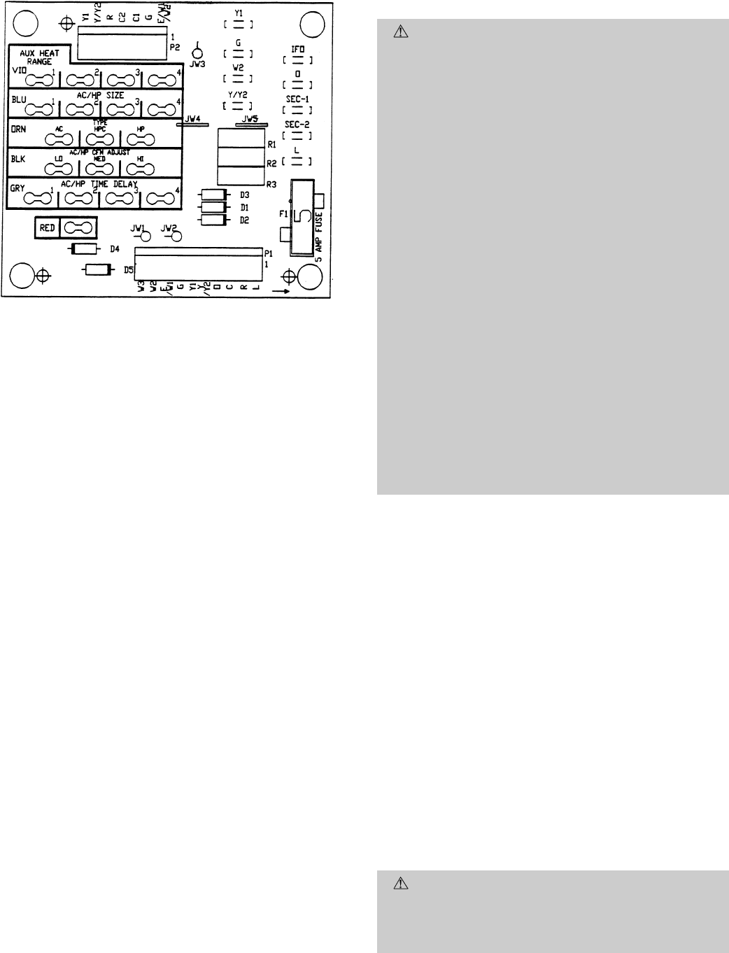
Connecting to Easy Select Interface Board
The Easy Select interface board is located in the control box
area. The Easy Select interface board is factory wired to the
motor, and factory default selections are preset.
Locate the five 18-gage thermostat lead wires of plug assem-
bly 1 (PL1) attached to the Easy Select interface board (See
Fig. 22 and wiring diagrams for units 589A048 and 060 on
pages 31 and 33.) These low voltage connection leads are iden-
tified by the colors red, green, yellow, brown, and white. Cut
the wires between the 2 wire ties approximately 4 in. from
the plug. Connect low-voltage leads to the thermostat. Se-
cure all cut wires in the control and splice boxes so they do
not interfere with the proper operation of the unit.
LEGEND
Field Control-Voltage Wiring
Field High-Voltage Wiring
NOTE: Use blue wire for 3-phase units only.
Fig. 21 — High- and Control-Voltage Connections
—21—
E. Heat Anticipator Setting
The room thermostat heat anticipator must be properly ad-
justed to ensure proper heating performance. Set the heat
anticipator, using an ammeter between the W and R termi-
nals to determine the exact required setting.
NOTE: For thermostat selection purposes, use 0.18 amp for
the approximate required setting.
Failure to make a proper heat anticipator adjustment will
result in improper operation, discomfort to the occupants of
the conditioned space, and inefficient energy utilization; how-
ever, the required setting may be changed slightly to provide
a greater degree of comfort for a particular installation.
F. Transformer Protection
The unit transformer protection may be one of 2 types.
The first transformer type may contain an auto. reset over-
current protector for control circuit protection. If this device
trips, it may reset without warning, starting the heating or
cooling section of this product. Use caution when servicing; if
overcurrent protector continues to trip, there is a problem in
the low-voltage electrical circuit, such as an electrical short,
ground, or transformer overload. Disconnect power, correct
the condition, and check for normal unit operation.
The second transformer type is of the energy-limiting type. It
is set to withstand a 30-second overload or shorted second-
ary condition.
PRE-START-UP
WARNING: Failure to observe the following warn-
ings could result in serious personal injury:
1. Follow recognized safety practices and wear protec-
tive goggles when checking or servicing refrigerant
system.
2. Do not operate compressor or provide any electric
power to unit unless compressor terminal cover is in
place and secured.
3. Do not remove compressor terminal cover until all
electrical sources are disconnected.
4. Relieve and reclaim all refrigerant from system be-
fore touching or disturbing anything inside termi-
nal box if refrigerant leak is suspected around com-
pressor terminals.
5. Never attempt to repair soldered connection while
refrigerant system is under pressure.
6. Do not use torch to remove any component. System
contains oil and refrigerant under pressure. To re-
move a component, wear protective goggles and pro-
ceed as follows:
a. Shut off gas supply and then electrical power to
unit.
b. Relieve and reclaim all refrigerant from system
using both high- and low-pressure ports.
c. Cut component connecting tubing with tubing cut-
ter and remove component from unit.
d. Carefully unsweat remaining tubing stubs when
necessary. Oil can ignite when exposed to torch
flame.
Proceed as follows to inspect and prepare the unit for initial
start-up:
1. Remove all access panels.
2. Read and follow instructions on all WARNING, CAU-
TION, and INFORMATION labels attached to, or shipped
with, unit.
3. Make the following inspections:
a. Inspect for shipping and handling damages such as
broken lines, loose parts, disconnected wires, etc.
b. Inspect for oil at all refrigerant tubing connections
and on unit base. Detecting oil generally indicates a
refrigerant leak. Leak-test all refrigerant tubing con-
nections using electronic leak detector, halide torch,
or liquid-soap solution. If a refrigerant leak is de-
tected, see Check for Refrigerant Leaks section on
page 23.
c. Inspect all field- and factory-wiring connections. Be
sure that connections are completed and tight.
d. Inspect coil fins. If damaged during shipping and han-
dling, carefully straighten fins with a fin comb.
4. Verify the following conditions:
CAUTION: Do not purge gas supply into the com-
bustion chamber. Do not use a match or other open flame
to check for gas leaks. Failure to follow this warning
could result in an explosion causing personal injury or
death.
LEGEND
IFO — Indoor (Evaporator) Fan On
JW — Jumper Wire
Fig. 22 — Easy Select Interface Board
—22—
a. Before lighting the unit for the first time, perform
the following: If the gas supply pipe was not purged
before connecting the unit, it will be full of air. It is
recommended that the ground joint union be loos-
ened, and the supply line be allowed to purge until
the odor of gas is detected. Never purge gas lines into
a combustion chamber. Immediately upon detection
of gas odor, retighten the union. Allow 5 minutes to
elapse, then light unit.
b. Make sure that condenser-fan blade is correctly po-
sitioned in fan orifice. Leading edge of condenser-fan
blade should be
1
⁄
2
in. maximum from plastic fan ori-
fice (see Fig. 23).
c. Make sure that air filter(s) is in place.
d. Make sure that condensate drain trap is filled with
water to ensure proper drainage.
e. Make sure that all tools and miscellaneous loose parts
have been removed.
START-UP
I. CHECK FOR REFRIGERANT LEAKS
Proceed as follows to locate and repair a refrigerant leak and
to charge the unit:
1. Locate leak and make sure that refrigerant system pres-
sure has been relieved and reclaimed from both high-
and low-pressure ports.
2. Repair leak following accepted practices.
NOTE: Install a filter drier whenever the system has been
opened for repair.
3. Add a small charge of R-22 refrigerant vapor to system
and leak-test unit.
4. Evacuate and reclaim refrigerant from refrigerant sys-
tem if additional leaks are not found.
5. Charge unit with R-22 refrigerant, using a volumetric-
charging cylinder or accurate scale. Refer to unit rating
plate for required charge. Be sure to add extra refriger-
ant to compensate for internal volume of filter drier.
II. START UP HEATING SECTION AND MAKE
ADJUSTMENTS
CAUTION: Complete the required procedures given
in Pre-Start-Up section on page 22 before starting the
unit.
Do not jumper any safety devices when operating the unit.
Make sure that burner orifices are properly aligned. Un-
stable operation may occur when the burner orifices in the
manifold are misaligned.
Follow the lighting instructions on the heating section
operation label (located inside the burner or blower access
door) to start the heating section.
NOTE: Make sure that gas supply has been purged, and that
all gas piping has been checked for leaks.
A. Check Heating Control
Start and check the unit for proper heating control operation
as follows. (See furnace lighting instructions located inside
burner or blower access panel.)
1. Place the room thermostat SYSTEM switch in the HEAT
position and the fan switch in the AUTO. position.
2. Set the heating temperature control of the thermostat
above room temperature.
3. The induced-draft motor will start.
4. After a call for heating, the main burner should light
within 5 seconds. If the burners do not light, there is a
22-second delay before another 5-second try. If the burn-
ers still do not light, this sequence is repeated. If the
burners do not light within 15 minutes from the initial
call for heat, there is a lockout. To reset the control, break
the 24-v power to W.
5. The evaporator fan will turn on 45 seconds after the flame
has been established. The evaporator fan will turn off
45 seconds after the thermostat has been satisfied.
B. Check Gas Input
Check gas input and manifold pressure after unit start-up.
(See Table 5.) If adjustment is required proceed as follows.
The rated gas inputs shown in Table 5 are for altitudes from
sea level to 2000 ft above sea level. These inputs are based
on natural gas with a heating value of 1050 Btu/ft
3
at 0.65
specific gravity, or propane gas with a heating value of 2500
Btu/ft
3
at 1.5 specific gravity. For elevations above 2000 ft,
reduce input 4% for each 1000 ft above sea level. When the
gas supply being used has a different heating value or spe-
cific gravity, refer to national and local codes, or contact your
distributor to determine the required orifice size.
CAUTION: These units are designed to consume the
rated gas inputs using the fixed orifices at specified mani-
fold pressures as shown in Table 5. DO NOT REDRILL
THE ORIFICES UNDER ANY CIRCUMSTANCES.
C. Adjust Gas Input
The gas input to the unit is determined by measuring the
gas flow at the meter or by measuring the manifold pressure.
Measuring the gas flow at the meter is recommended for natu-
ral gas units. The manifold pressure must be measured to
determine the input of propane gas units.
Fig. 23 — Fan Blade Clearance
—23—
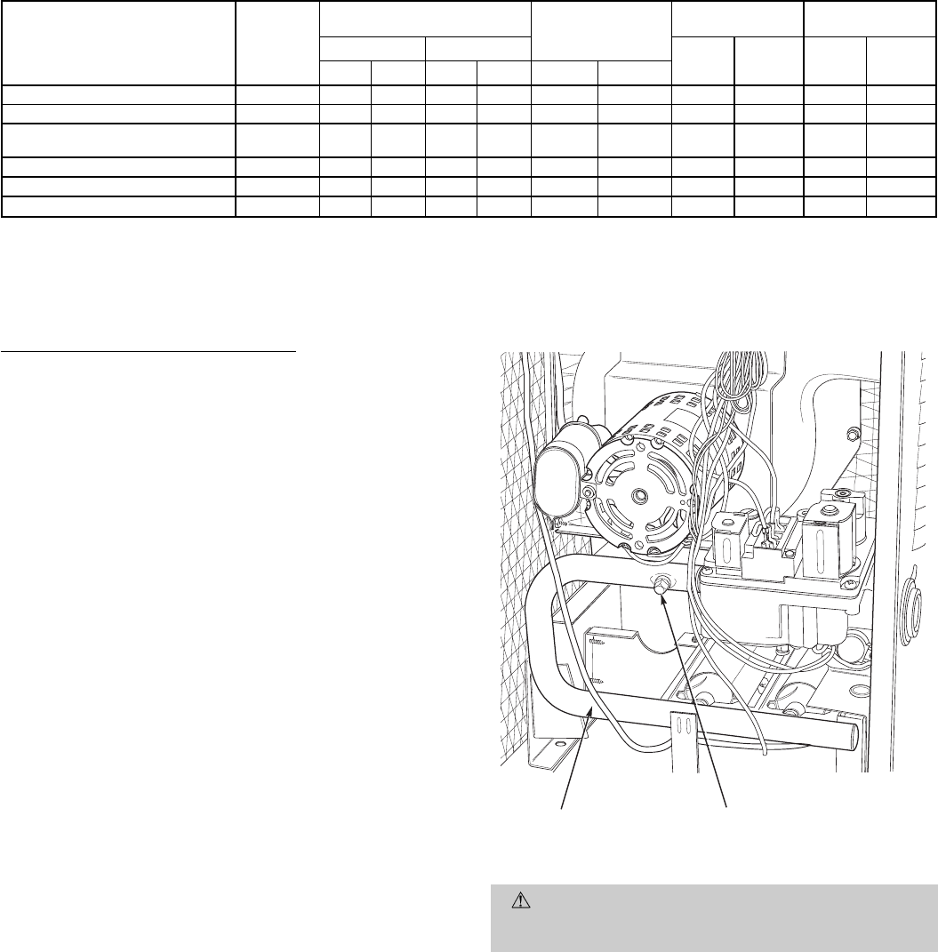
Table 5 — Rated Gas Inputs at Indicated Manifold Pressures
UNIT 588A, 589A NUMBER
OF
ORIFICES
GAS SUPPLY PRESSURE
(in. wg) MANIFOLD
PRESSURE
(in. wg)
NATURAL GAS PROPANE*
Natural Propane Orifice
Drill
Size
Heating
Input
(Btuh)†
Orifice
Drill
Size
Heating
Input
(Btuh)†
Min Max Min Max Natural Propane
018040, 024040, 030040 1 4.0 13.0 4.0 13.0 3.5 3.1 32 40,000 41 40,000
024060, 030060, 036060, 042060 2 4.0 13.0 4.0 13.0 3.5 3.3 40 56,000 47 54,000
030080, 036080, 042080,
048080, 060080 2 4.0 13.0 4.0 13.0 3.5 3.4 32 80,000 42 80,000
036100, 042100, 048100, 060100 2 4.0 13.0 4.0 13.0 3.5 3.7 30 95,000 40 95,000
036120, 042120, 048120, 060120 3 4.0 13.0 4.0 13.0 3.5 3.5 32 120,000 42 115,000
048140, 060140 3 4.0 13.0 4.0 13.0 3.5 3.4 31 136,000 40 133,000
*When a unit is converted to propane, different size orifices must be used. See separate natural-to-propane conversion kit
instructions.
†Based on altitudes from sea level to 2000 ft above sea level. For altitudes above 2000 ft: reduce input rating 4% for each
additional 1000 ft above 2000 ft. In Canada, from 2000 ft above sea level to 4500 ft above sea level, derate the unit 10%.
NOTE: Unit size 018 is 588A only.
Measure Gas Flow (Natural Gas Units)
Minor adjustment to the gas flow can be made by changing
the manifold pressure. The manifold pressure must be main-
tained between 3.4 and 3.6 in. wg. If larger adjustments are
required, change main burner orifices following the recom-
mendations of national and local codes.
NOTE: All other appliances that use the same meter must
be turned off when gas flow is measured at the meter.
Proceed as follows:
1. Turn off gas supply to unit.
2. Remove pipe plug on manifold (see Fig. 24), then con-
nect manometer at this point. Turn on gas to unit.
3. Record number of seconds for gas meter test dial to make
one revolution.
4. Divide number of seconds in Step 3 into 3600 (number
of seconds in one hour).
5. Multiply result of Step 4 by the number of cu ft shown
for one revolution of test dial to obtain cu ft of gas flow
per hour.
6. Multiply result of Step 5 by Btu heating value of gas to
obtain total measured input in Btuh. Compare this value
with heating input shown in Table 5. (Consult the local
gas supplier if the heating value of gas is not known.)
EXAMPLE: Assume that the size of test dial is 1 cu ft, one
revolution takes 30 seconds, and the heating value of the gas
is 1050 Btu/ft
3
. Proceed as follows:
1. 30 seconds to complete one revolution.
2. 3600 ÷ 30 = 120.
3. 120x1=120ft
3
of gas flow/hr.
4. 120 x 1050 = 126,000 Btuh input.
If the desired gas input is 120,000 Btuh, only a minor change
in the manifold pressure is required.
Observe manifold pressure and proceed as follows to ad-
just gas input:
1. Remove cover screw over regulator adjustment screw on
gas valve.
2. Turn regulator adjustment screw clockwise to increase
gas input, or turn regulator adjustment screw counter-
clockwise to decrease input. Manifold pressure must be
between 3.4 and 3.6 in. wg.
WARNING: Unsafe operation of the unit may result
if manifold pressure is outside this range. Personal in-
jury or unit damage may result.
3. Replace cover screw cap on gas valve.
4. Turn off gas supply to unit. Remove manometer from
pressure tap and replace pipe plug on gas valve. Turn
on gas to unit and check for leaks.
MANIFOLD PIPE PLUG
Fig. 24 — Burner Assembly
—24—
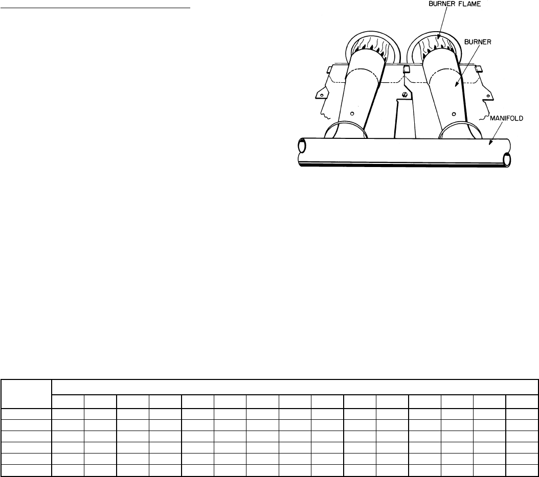
Measure Manifold Pressure (Propane Units)
The main burner orifices on a propane gas unit are sized for
the unit rated input when the manifold pressure reading
matches the level specified in Table 5.
Proceed as follows to adjust gas input on a propane gas unit:
1. Turn off gas to unit.
2. Remove pipe plug on manifold (see Fig. 24), then con-
nect manometer at this point.
3. Turn on gas to unit.
4. Remove cover screw over regulator adjustment screw on
gas valve.
5. Adjust regulator adjustment screw to the correct mani-
fold pressure, as specified in Table 5. Turn adjusting
screw clockwise to increase manifold pressure, or turn
adjusting screw counterclockwise to decrease manifold
pressure.
6. Replace cover screw.
7. Turn off gas to unit. Remove manometer from pressure
tap. Replace pipe plug on gas valve, then turn on gas to
unit. Check for leaks.
D. Check Burner Flame
With burner access panel removed, observe the unit heating
operation. Watch the burner flames to see if they are light
blue and soft in appearance, and that the flames are approxi-
mately the same for each burner. Propane will have blue flame
with yellow tips. See Fig. 25. Refer to Maintenance section
for information on burner removal.
E. Airflow and Temperature Rise
The heating section for each size unit is designed and ap-
proved for heating operation within the temperature-rise range
stamped on the unit rating plate.
Table 6 shows the approved temperature-rise range for each
heating input, and the air delivery cfm at various tempera-
ture rises. The heating operation airflow must produce a tem-
perature rise that falls within the approved range.
Refer to Indoor Airflow and Airflow Adjustments section on
page 35 to adjust heating airflow when required.
Table 6 — Air Delivery (Cfm) at Indicated Temperature Rise and Rated Heating Input
HEATING
INPUT
(Btuh)
TEMPERATURE RISE °F
20 25 30 35 40 45 50 55 60 65 70 75 80 85 90
40,000 1389 1111 926 794 694 617 556 ————————
56,000 2083 1667 1389 1190 1042 926 833 758 ———————
80,000 2778 2222 1852 1587 1389 1235 1111 1010 926 855 794 ————
95,000 3472 2778 2315 1984 1736 1543 1389 1263 1157 1068 992 926 868 — —
120,000 4167 3333 2778 2381 2083 1852 1667 1515 1389 1282 1190 1111 1042 980 926
136,000 5037 4029 3358 2878 2518 2238 2014 1831 1679 1549 1439 1343 1259 1185 1119
NOTE: Dashed areas do not fall within the approved temperature rise range of the unit.
Fig. 25 — Monoport Burners
—25—
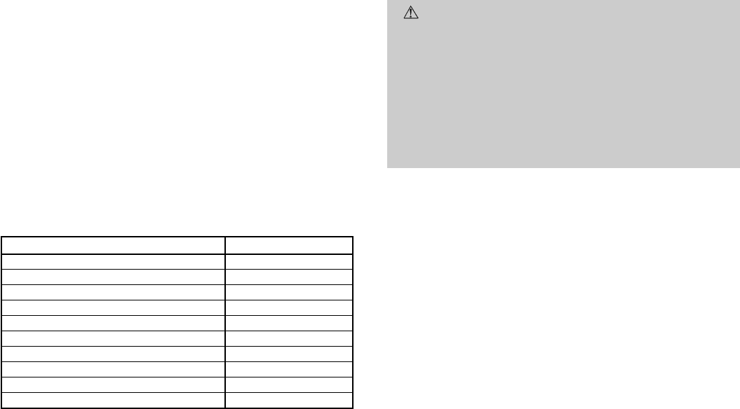
F. Heating Sequence of Operation
See Fig. 26-33 and unit wiring label.
On a call for heating, terminal ‘‘W’’ of the thermostat is en-
ergized, starting the induced-draft motor. When the hall-
effect sensor on the induced-draft motor senses that it has
reached the required speed, the burner sequence begins. This
function is performed by the integrated gas control (IGC). The
evaporator-fan motor is energized 45 seconds after flame is
established. When the thermostat is satisfied and ‘‘W’’is deen-
ergized, the burners stop firing and the evaporator-fan motor
shuts off after a 45-second time-off delay.
ALED (light-emitting diode) indicator is provided on the con-
trol board to monitor operation. The control board is located
by removing the burner access panel. During normal opera-
tion, the LED is continuously on. See Table 7 for error codes.
Table 7 — LED Indications
ERROR CODE LED INDICATION
Normal Operation On
Hardware Failure Off
Fan On/Off Delay Modified 1 Flash
Limit Switch Fault 2 Flashes
Flame Sense Fault 3 Flashes
Four Consecutive Limit Switch Faults 4 Flashes
Ignition Lockout Fault 5 Flashes
Induced-Draft Motor Fault 6 Flashes
Rollout Switch Fault 7 Flashes
Internal Control Fault 8 Flashes
NOTES:
1. There is a 3-second pause between error code displays.
2. If more than one error code exists, all applicable error codes will be
displayed in numerical sequence.
3. This chart is on the wiring diagram located inside the burner access
panel.
G. Limit Switches
Normally-closed limit switch (LS) completes the control cir-
cuit through the thermostat R circuit. Should the leaving-air
temperature rise above the maximum allowable tempera-
ture, the limit switch opens and the R control circuit ‘‘breaks.’’
Any interruption in the R control circuit instantly closes the
gas valve and stops gas flow to the burners and pilot. The
blower motor continues to run until LS resets.
When the air temperature at the limit switch drops to the
low-temperature setting of the limit switch, the switch closes
and completes the R control circuit. The electric-spark igni-
tion system cycles and the unit returns to normal heating
operation.
H. Auxiliary Limit Switch — Rollout
The function of the switch is to close the main gas valve in
the event of flame rollout. The switch is located above the
main burners. When the temperature at the auxiliary switch
reaches the maximum allowable temperature, the R control
circuit trips, closing the gas valve and stopping gas flow to
the burners. The indoor (evaporator) fan motor (IFM) and in-
duced draft motor continue to run until switch is reset.
III. START UP COOLING SECTION AND MAKE
ADJUSTMENTS
CAUTION: Complete the required procedures given
in the Pre-Start-Up section on page 22 before starting
the unit.
Do not jumper any safety devices when operating the
unit.
Do not operate the compressor when the outdoor tem-
perature is below 40 F (unless accessory low-ambient
kit is installed).
Do not rapid-cycle the compressor. Allow 5 minutes be-
tween ‘‘on’’ cycles to prevent compressor damage.
Checking Cooling Control Operation
Start and check the unit for proper cooling control operation
as follows:
1. Place room thermostat SYSTEM switch in OFF posi-
tion. Observe that blower motor starts when FAN switch
is placed in ON position and shuts down when FAN switch
is placed in AUTO. position.
2. Place SYSTEM switch in COOLposition and FAN switch
in AUTO. position. Set cooling control below room tem-
perature. Observe that compressor, condenser fan, and
evaporator blower motors start. Observe that cooling
cycle shuts down when control setting is satisfied. The
evaporator fan will continue to run for 30 seconds.
3. When using an auto.-changeover room thermostat, place
both SYSTEM and FAN switches in AUTO. positions.
Observe that unit operates in heating mode when tem-
perature control is set to ‘‘call for heating’’ (above room
temperature) and operates in cooling mode when tem-
perature control is set to ‘‘call for cooling’’ (below room
temperature).
IMPORTANT: Three-phase, scroll compressor units
(588A048,060 and 589A036-060) are direction-oriented. These
units must be checked to ensure proper compressor 3-phase
power lead orientation. If not corrected within 5 minutes, the
internal protector will shut off the compressor. The 3-phase
power leads to the unit must be reversed to correct rotation.
When turning backwards, scroll compressors emit elevated
noise levels, and the difference between compressor suction
and discharge pressures may be dramatically lower than
normal.
(Text continued on page 35.)
—26—
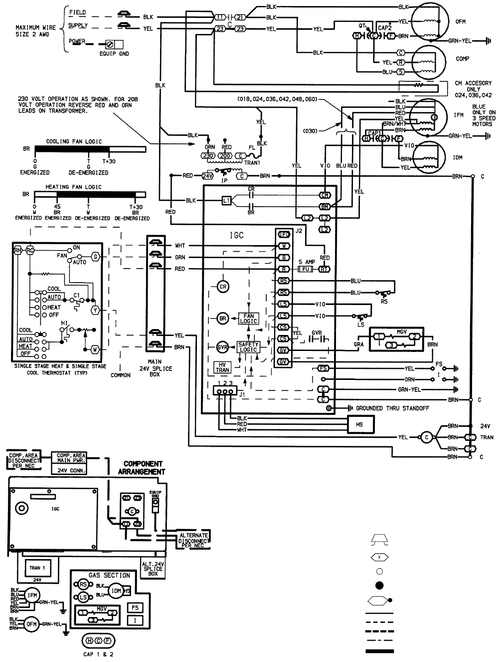
LEGEND
AWG — American Wire Gage
BR — Blower Relay
C—Contactor
CAP — Capacitor
CH — Crankcase Heater
COMP — Compressor Motor
CR — Combustion Relay
EQUIP — Equipment
FL — Fuse Link
FS — Flame Sensor
FU — Fuse
GND — Ground
GVR — Gas Valve Relay
HS — Hall Effect Sensor
HV TRAN — High-Voltage Transformer
I—Ignitor
IDM — Induced-Draft Motor
IFM — Indoor-Fan Motor
IGC — Integrated Gas Control
IP — Internal Protector
LS — Limit Switch
MGV — Main Gas Valve
NEC — National Electrical Code
OFM — Outdoor-Fan Motor
PWR — Power
QT — Quadruple Terminal
RS — Rollout Switch
TRAN — Transformer
Field Splice
Terminal (Marked)
Terminal (Unmarked)
Splice
Splice (Marked)
Factory Wiring
Field Control Wiring
Field Power Wiring
Accessory or Optional Wiring
To Indicate Common Potential
Only, Not to Represent Wiring
NOTES:
1. If any of the original wire furnished must be replaced, it must be replaced
with type 90 C wire or its equivalent.
2. Use copper conductors only.
Fig. 26 — 208/230-1-60 Wiring Diagram, Units 588A018-060
—27—

LEGEND
AWG — American Wire Gage
BR — Blower Relay
C—Contactor
CAP — Capacitor
CH — Crankcase Heater
COMP — Compressor Motor
CR — Combustion Relay
EQUIP — Equipment
FL — Fuse Link
FS — Flame Sensor
FU — Fuse
GND — Ground
GVR — Gas Valve Relay
HS — Hall Effect Sensor
HV TRAN — High-Voltage Transformer
I—Ignitor
IDM — Induced-Draft Motor
IFM — Indoor-Fan Motor
IGC — Integrated Gas Control
IP — Internal Protector
LS — Limit Switch
MGV — Main Gas Valve
NEC — National Electrical Code
OFM — Outdoor-Fan Motor
PWR — Power
QT — Quadruple Terminal
RS — Rollout Switch
TRAN — Transformer
Field Splice
Terminal (Marked)
Terminal (Unmarked)
Splice
Splice (Marked)
Factory Wiring
Field Control Wiring
Field Power Wiring
Accessory or Optional Wiring
To Indicate Common Potential
Only, Not to Represent Wiring
NOTES:
1. If any of the original wire furnished must be replaced, it must be replaced
with type 90 C wire or its equivalent.
2. Use copper conductors only.
Fig. 27 — 208/230-3-60 Wiring Diagram, Units 588A030-060
—28—
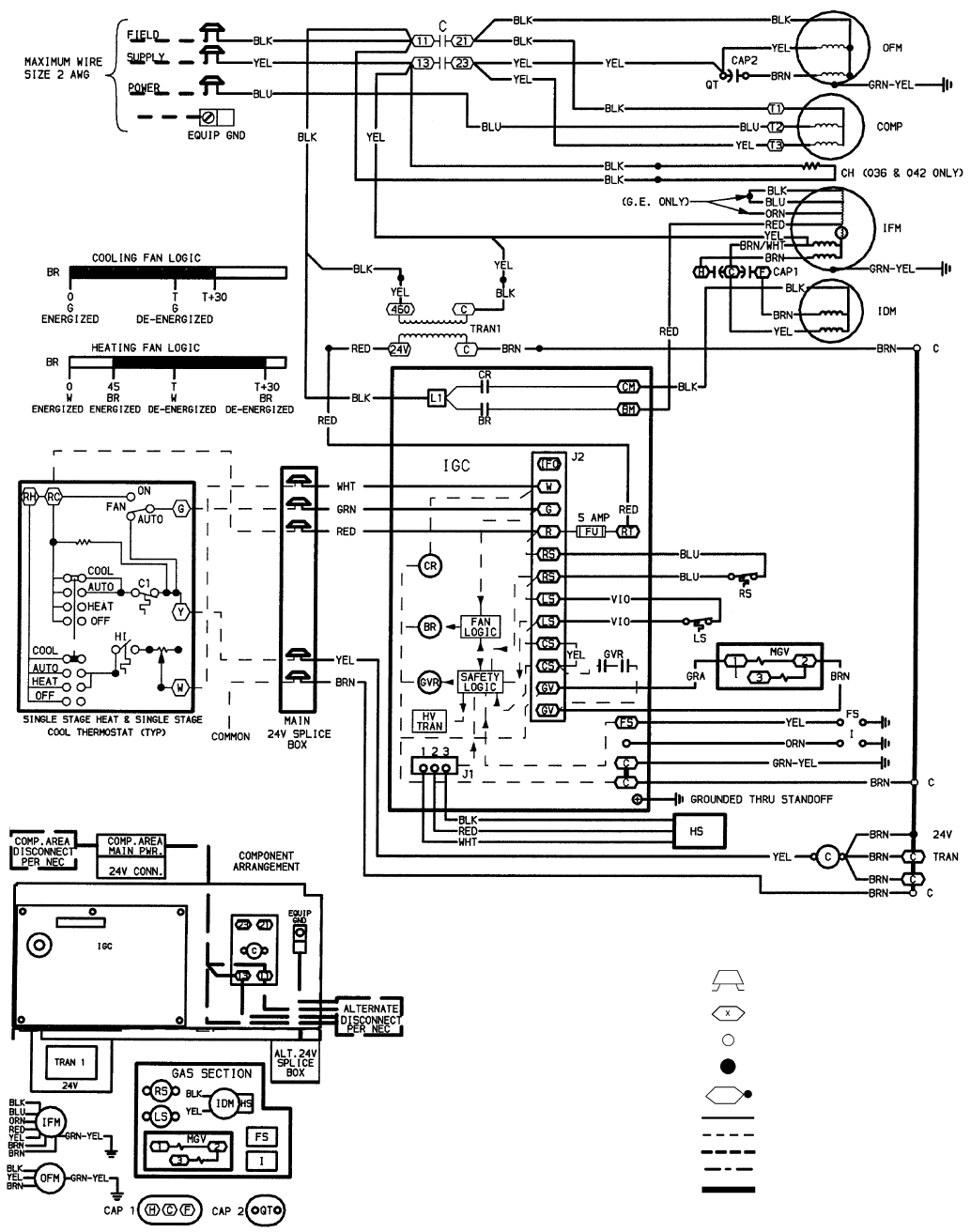
LEGEND
AWG — American Wire Gage
BR — Blower Relay
C—Contactor
CAP — Capacitor
CH — Crankcase Heater
COMP — Compressor Motor
CR — Combustion Relay
EQUIP — Equipment
FS — Flame Sensor
FU — Fuse
GND — Ground
GVR — Gas Valve Relay
HS — Hall Effect Sensor
HV TRAN — High-Voltage Transformer
I—Ignitor
IDM — Induced-Draft Motor
IFM — Indoor-Fan Motor
IGC — Integrated Gas Control
LS — Limit Switch
MGV — Main Gas Valve
NEC — National Electrical Code
OFM — Outdoor-Fan Motor
PWR — Power
QT — Quadruple Terminal
RS — Rollout Switch
TRAN — Transformer
Field Splice
Terminal (Marked)
Terminal (Unmarked)
Splice
Splice (Marked)
Factory Wiring
Field Control Wiring
Field Power Wiring
Accessory or Optional Wiring
To Indicate Common Potential
Only, Not to Represent Wiring
NOTES:
1. If any of the original wire furnished must be replaced, it must be replaced
with type 90 C wire or its equivalent.
2. Use copper conductors only.
Fig. 28 — 460-3-60 Wiring Diagram, Units 588A036-060
—29—
LEGEND
AWG — American Wire Gage
BR — Blower Relay
C—Contactor
CAP — Capacitor
COMP — Compressor Motor
CR — Combustion Relay
EQUIP — Equipment
FL — Fuse Link
FS — Flame Sensor
FU — Fuse
GND — Ground
GVR — Gas Valve Relay
HS — Hall Effect Sensor
HV TRAN — High-Voltage Transformer
I—Ignitor
IDM — Induced-Draft Motor
IFM — Indoor-Fan Motor
IGC — Integrated Gas Control
LS — Limit Switch
MGV — Main Gas Valve
NEC — National Electrical Code
OFM — Outdoor-Fan Motor
PWR — Power
QT — Quadruple Terminal
RS — Rollout Switch
ST — Start Thermistor
TRAN — Transformer
Field Splice
Terminal (Marked)
Terminal (Unmarked)
Splice
Splice (Marked)
Factory Wiring
Field Control Wiring
Field Power Wiring
Accessory or Optional Wiring
To Indicate Common Potential
Only, Not to Represent Wiring
NOTES:
1. If any of the original wire furnished must be replaced, it must be
replaced with type 90 C wire or its equivalent.
2. Use copper conductors only.
Fig. 29 — 208/230-1-60 Wiring Diagram, Units 589A024-042
—30—
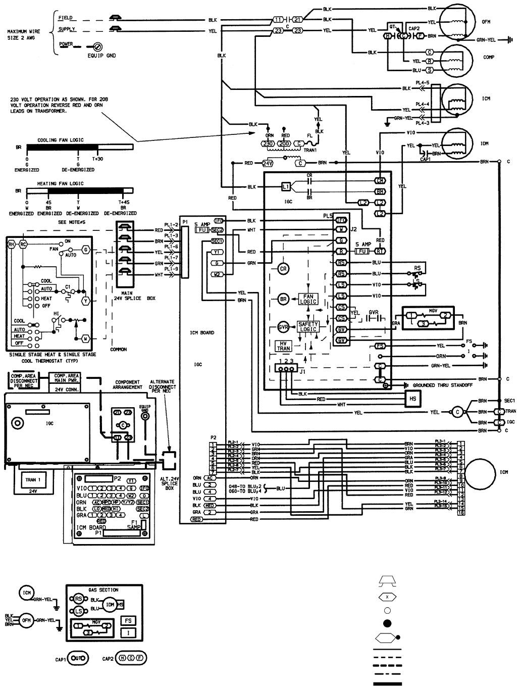
LEGEND
AWG — American Wire Gage
BR — Blower Relay
C—Contactor
CAP — Capacitor
COMP — Compressor Motor
CR — Combustion Relay
EQUIP — Equipment
FL — Fuse Link
FS — Flame Sensor
FU — Fuse
GND — Ground
GVR — Gas Valve Relay
HS — Hall Effect Sensor
HV TRAN — High-Voltage Transformer
I—Ignitor
ICM — Integrated Control Motor
IDM — Induced-Draft Motor
IFM — Indoor-Fan Motor
IGC — Integrated Gas Control
LS — Limit Switch
MGV — Main Gas Valve
NEC — National Electrical Code
OFM — Outdoor-Fan Motor
PWR — Power
QT — Quadruple Terminal
RS — Rollout Switch
SEC — Secondary
TRAN — Transformer
Field Splice
Terminal (Marked)
Terminal (Unmarked)
Splice
Splice (Marked)
Factory Wiring
Field Control Wiring
Field Power Wiring
Accessory or Optional Wiring
To Indicate Common Potential
Only, Not to Represent Wiring
NOTES:
1. If any of the original wire furnished must be replaced, it must be
replaced with type 90 C wire or its equivalent.
2. Use copper conductors only.
Fig. 30 — 208/230-1-60 Wiring Diagram, Units 589A048,060
—31—
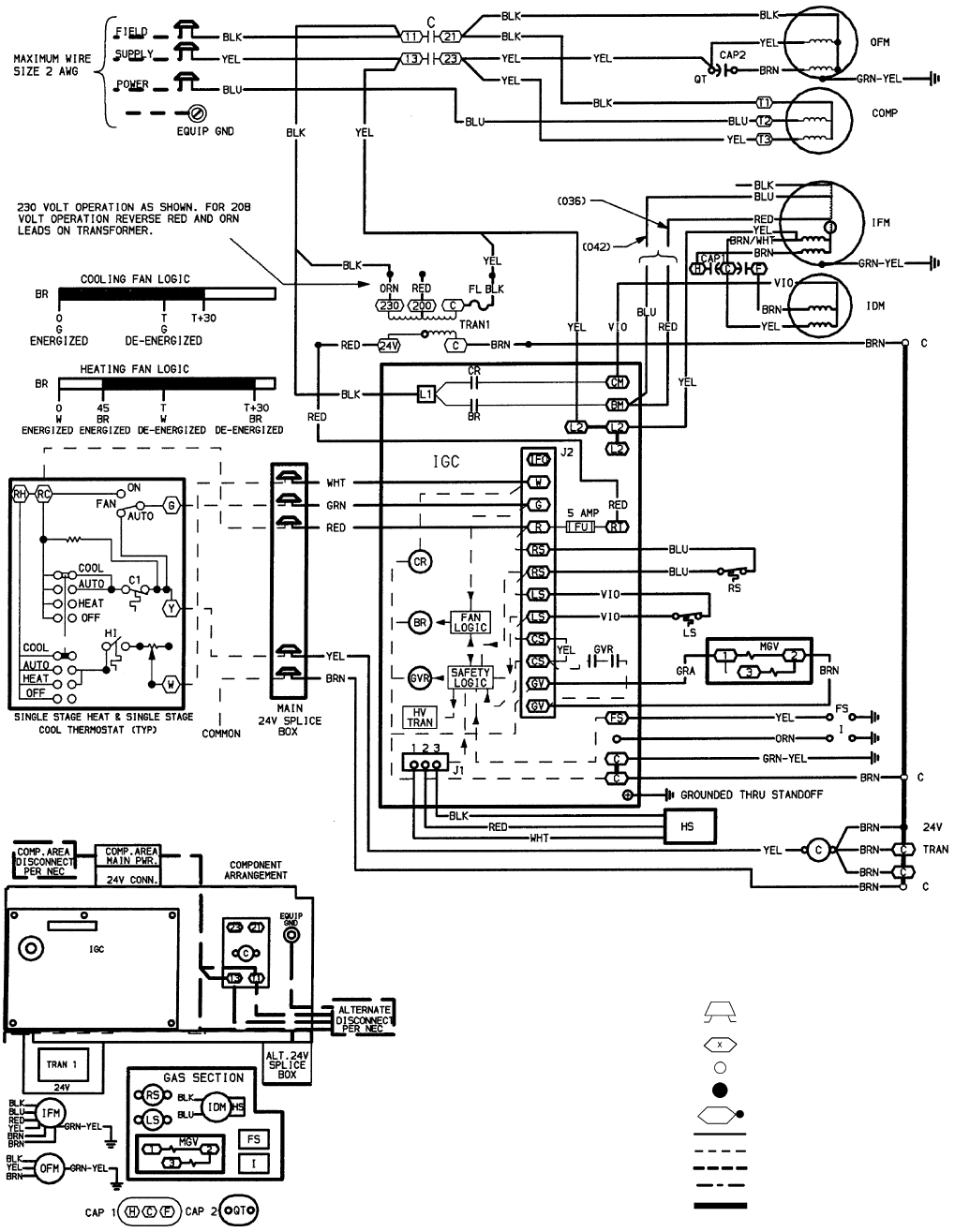
LEGEND
AWG — American Wire Gage
BR — Blower Relay
C—Contactor
CAP — Capacitor
COMP — Compressor Motor
CR — Combustion Relay
EQUIP — Equipment
FL — Fuse Link
FS — Flame Sensor
FU — Fuse
GND — Ground
GVR — Gas Valve Relay
HS — Hall Effect Sensor
HV TRAN — High-Voltage Transformer
I—Ignitor
IDM — Induced-Draft Motor
IFM — Indoor-Fan Motor
IGC — Integrated Gas Control
LS — Limit Switch
MGV — Main Gas Valve
NEC — National Electrical Code
OFM — Outdoor-Fan Motor
PWR — Power
QT — Quadruple Terminal
RS — Rollout Switch
TRAN — Transformer
Field Splice
Terminal (Marked)
Terminal (Unmarked)
Splice
Splice (Marked)
Factory Wiring
Field Control Wiring
Field Power Wiring
Accessory or Optional Wiring
To Indicate Common Potential
Only, Not to Represent Wiring
NOTES:
1. If any of the original wire furnished must be replaced, it must be
replaced with type 90 C wire or its equivalent.
2. Use copper conductors only.
Fig. 31 — 208/230-3-60 Wiring Diagram, Units 589A036-042
—32—
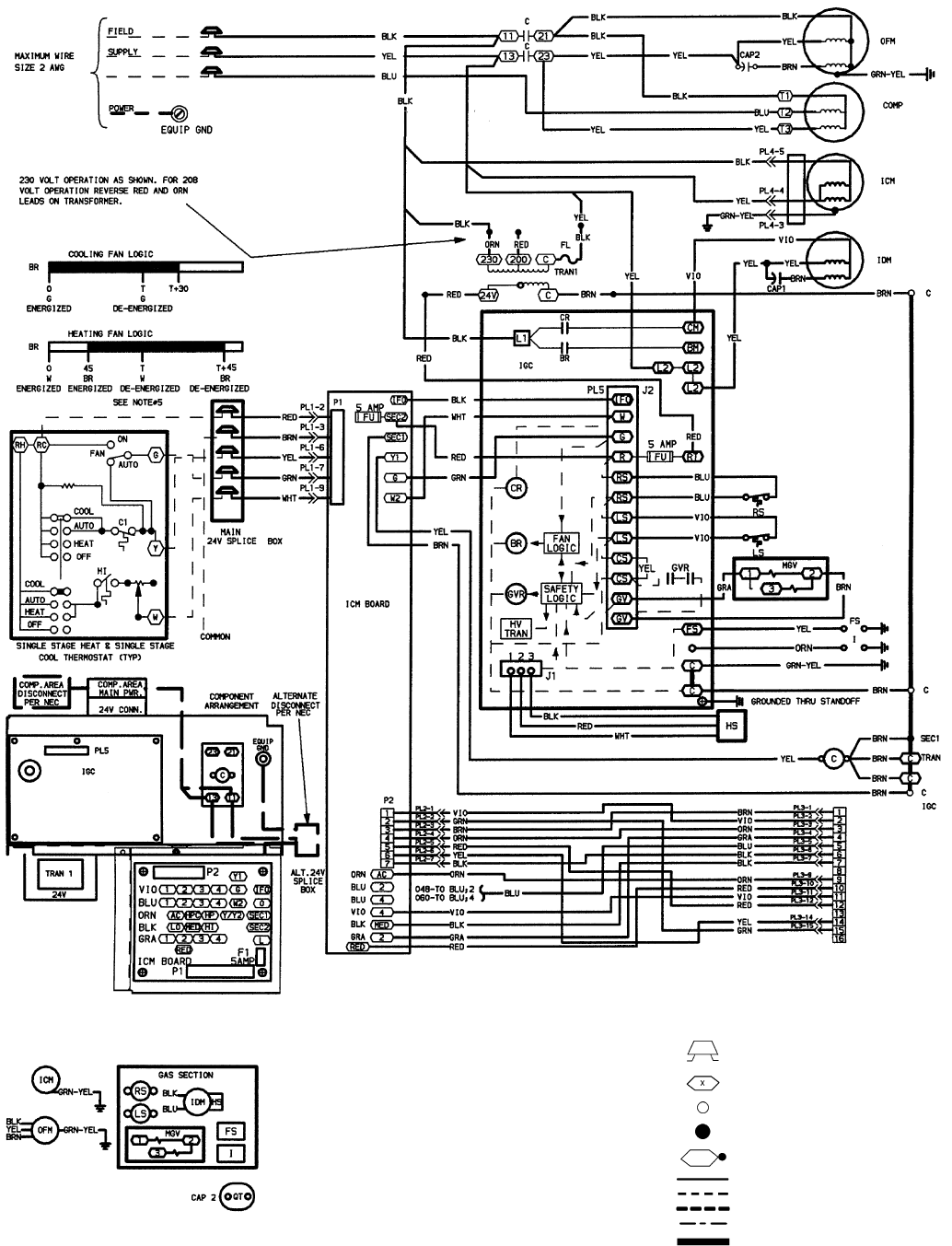
LEGEND
AWG — American Wire Gage
BR — Blower Relay
C—Contactor
CAP — Capacitor
COMP — Compressor Motor
CR — Combustion Relay
EQUIP — Equipment
FL — Fuse Link
FS — Flame Sensor
FU — Fuse
GND — Ground
GVR — Gas Valve Relay
HS — Hall Effect Sensor
HV TRAN — High-Voltage Transformer
I—Ignitor
ICM — Integrated Control Motor
IDM — Induced-Draft Motor
IFM — Indoor-Fan Motor
IGC — Integrated Gas Control
LS — Limit Switch
MGV — Main Gas Valve
NEC — National Electrical Code
OFM — Outdoor-Fan Motor
PWR — Power
QT — Quadruple Terminal
RS — Rollout Switch
SEC — Secondary
TRAN — Transformer
Field Splice
Terminal (Marked)
Terminal (Unmarked)
Splice
Splice (Marked)
Factory Wiring
Field Control Wiring
Field Power Wiring
Accessory or Optional Wiring
To Indicate Common Potential
Only, Not to Represent Wiring
NOTES:
1. If any of the original wire furnished must be replaced, it must be
replaced with type 90 C wire or its equivalent.
2. Use copper conductors only.
Fig. 32 — 208/230-3-60 Wiring Diagram, Units 589A048,060
—33—
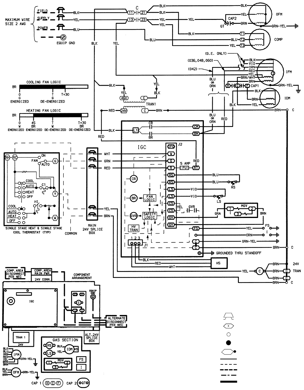
LEGEND
AWG — American Wire Gage
BR — Blower Relay
C—Contactor
CAP — Capacitor
COMP — Compressor Motor
CR — Combustion Relay
EQUIP — Equipment
FS — Flame Sensor
FU — Fuse
GND — Ground
GVR — Gas Valve Relay
HS — Hall Effect Sensor
HV TRAN — High-Voltage Transformer
I—Ignitor
IDM — Induced-Draft Motor
IFM — Indoor-Fan Motor
IGC — Integrated Gas Control
LS — Limit Switch
MGV — Main Gas Valve
NEC — National Electrical Code
OFM — Outdoor-Fan Motor
PWR — Power
QT — Quadruple Terminal
RS — Rollout Switch
TRAN — Transformer
Field Splice
Terminal (Marked)
Terminal (Unmarked)
Splice
Splice (Marked)
Factory Wiring
Field Control Wiring
Field Power Wiring
Accessory or Optional Wiring
To Indicate Common Potential
Only, Not to Represent Wiring
NOTES:
1. If any of the original wire furnished must be replaced, it must be re-
placed with type 90 C wire or its equivalent.
2. Use copper conductors only.
Fig. 33 — 460-3-60 Wiring Diagram, Units 589A036-048
—34—
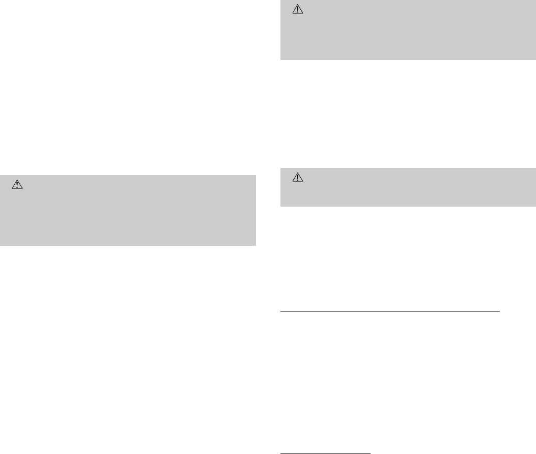
B. Checking and Adjusting Refrigerant Charge
The refrigerant system is fully charged with R-22 refriger-
ant, tested, and factory-sealed.
NOTE: Adjustment of the refrigerant charge is not required
unless the unit is suspected of not having the proper R-22
charge.
A superheat charging label is attached to the inside of the
compressor access door. The label includes a ‘‘Superheat Charg-
ing Table’’ and a ‘‘Required Suction-Tube (F) Temperature’’
chart.
An accurate superheat, thermocouple-, or thermistor-type ther-
mometer, a sling psychrometer, and a gage manifold are re-
quired when using the superheat charging method for evalu-
ating the unit charge. Do not use mercury or small dial-type
thermometers because they are not adequate for this type of
measurement.
CAUTION: When evaluating the refrigerant charge,
an indicated adjustment to the specified factory charge
must always be very minimal. If a substantial adjust-
ment is indicated, an abnormal condition exists some-
where in the cooling system, such as insufficient airflow
across either coil or both coils.
Proceed as follows:
1. Remove caps from low- and high-pressure service
fittings.
2. Using hoses with valve core depressors, attach low- and
high-pressure gage hoses to low- and high-pressure serv-
ice fittings, respectively.
3. Start unit in Cooling mode and let unit run until sys-
tem pressures stabilize.
4. Measure and record the following:
a. Outdoor ambient-air temperature (F db).
b. Evaporator inlet-air temperature (F wb).
c. Suction-tube temperature (F) at low-side service
fitting.
d. Suction (low-side) pressure (psig).
5. Using ‘‘Superheat Charging Table,’’ compare outdoor-
air temperature (F db) with evaporator inlet-air tem-
perature (F wb) to determine desired system operating
superheat temperature. See Tables 8A-8H and 9A-9F.
6. Using ‘‘Required Suction-Tube Temperature (F)’’ table,
compare desired superheat temperature with suction (low-
side) operating pressure (psig) to determine proper suction-
tube temperature. See Table 10.
7. Compare actual suction-tube temperature with proper
suction-tube temperature. Using a tolerance of ± 3° F,
add refrigerant if actual temperature is more than 3° F
higher than proper suction-tube temperature, or re-
move refrigerant if actual temperature is more than
3° F lower than required suction-tube temperature.
NOTE: If the problem causing the inaccurate readings is a
refrigerant leak, refer to Check for Refrigerant Leaks section
on page 23.
C. Indoor Airflow and Airflow Adjustments
CAUTION: For cooling operation, the recommended
airflow is 350 to 450 cfm for each 12,000 Btuh of rated
cooling capacity. For heating operation, the airflow must
produce a temperature rise that falls within the range
stamped on the unit rating plate.
Table 6 shows the temperature rise at various airflow rates.
Tables 11-14 show both heating and cooling airflows at vari-
ous external static pressures. See Tables 15 and 16 for ICM
(Integrated Control Motor) units air delivery. Refer to these
tables to determine the airflow for the system being in-
stalled. See Table 17 for wet coil pressure drop.
NOTE: Be sure that all supply- and return-air grilles are open,
free from obstructions, and adjusted properly.
WARNING: Shut off gas supply then disconnect elec-
trical power to the unit before changing blower speed.
Electrical shock can cause personal injury or death.
Airflow can be changed by changing the lead connections of
the blower motor.
Unit 588A two- or 3-speed motors (except size 030) are fac-
tory wired for low speed operation. Unit 588A030 is factory
wired for medium speed. Units 589A024,036, and 048 (460 v)
two- or 3-speed motors are factory wired for low speed; units
589A030 and 042 are factory wired for medium speed.
For 208/230-v and A.O. Smith 460-v Blower Motors
The motor leads are color-coded as follows:
3-SPEED 2-SPEED
black = high speed black = high speed
blue = medium speed red = low speed
red = low speed
To change the speed of the blower motor, remove the fan mo-
tor speed leg lead from the blower relay (BR). This wire is
attached to terminal BM for single-phase and 3-phase units.
To change the speed, remove and replace with lead for de-
sired blower motor speed. Insulate the removed lead to avoid
contact with chassis parts.
For 460-v GE Motors
The motor leads are color coded as follows:
3-SPEED 2-SPEED
black = high black = high
blue = jumper blue = jumper
orange = medium red = low
red = low
To change the speed of the blower motor, remove fan motor
speed lead from the blower relay (BR) and replace with the
lead for the desired blower motor speed. The motor speed lead
is attached to terminal BM. Insulate removed lead end to avoid
contact with chassis parts. On 3-speed motors only, connect
orange lead to terminal BM of BR. To select high speed on
460-v GE motors, separate the black (female QC) from the
blue lead (male QC) and connect the black lead to the BR.
Insulate the blue lead to avoid contact with any chassis parts.
—35—
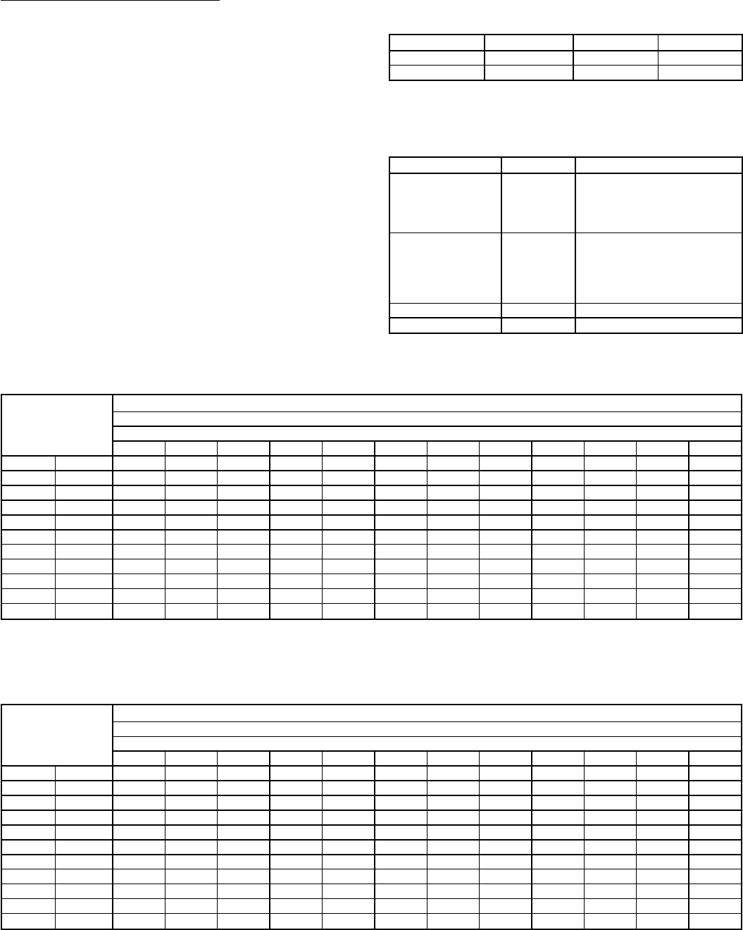
For Integrated Control Motors (ICM)
To configure the 589Aunit, move the 5 Easy Select board wires
to the terminals which control the airflow. Refer to the Easy
Select interface board (Fig. 22) located next to the terminals
and to Fig. 30 and 32.
Perform the following steps for basic system configuration.
AUX HEAT RANGE (VIO) — The airflow for unit 589A is
preset at the factory. The airflow selection must not be set at
a setting lower than the default. Refer to Table 15 for airflow
and gas heat input for terminals 1-4.
AC/HP SIZE (BLU) — The preset factory default selection
forAC/HP SIZE (air conditioner/heat pump) is set to 400 cfm/
ton. The selection pins are configured for 350 cfm/ton and
400 cfm/ton.
TYPE (ORN) — The TYPE is a preset factory default selec-
tion. The preset factory default setting is AC for the 589A
units. Default setting should not be altered.
AC/HP CFM ADJUST (BLK) — The preset factory default
selection is MED. Selections HI and LO will adjust the air-
flow supplied for all operational modes (see following table).
The selection options allow installer to adjust airflow to meet
such individual needs as noise and static compensation, etc.
MODE FAN ONLY COOLING HEATING
LO - Adjust −15% −10% −10%
HI - Adjust 15% 10% 10%
AC/HP TIME DELAY (GRY) — Four motor operation delay
options are provided to customize system operation. See table
below:
OPTION TERMINAL DESCRIPTION
30-Sec On/60-Sec
Off Delay Profile 1
Used when it is desirable
to allow system coils time
to heat up or cool down
prior to airflow. Enhances
system efficiency.
No Delay Option 2
Preset factory default setting for
589A. Used for servicing or
when other components are
used to perform a delay func-
tion (e.g., integrated gas
control).
30-Sec Off Delay 3 Enhances system efficiency.
45-Sec Off Delay 4 Enhances system efficiency.
Table 8A — Superheat Charging Table, 588A018
TEMP (F)
OUTDOOR
ENTERING
AIR
INDOOR AIR — CFM
600
Indoor Air — Ewb (F)
54 56 58 60 62 64 66 68 70 72 74 76
65 SPH 17.3 18.5 19.6 20.8 24.2 27.7 28.5 29.3 29.3 29.3 29.3 29.3
70 SPH 13.8 14.9 16.1 17.3 20.7 24.1 25.7 27.3 27.3 27.3 27.3 27.3
75 SPH 10.2 11.4 12.5 13.7 17.1 20.6 22.9 25.2 25.2 25.2 25.2 25.2
80 SPH 8.2 8.8 9.5 10.2 13.6 17.0 20.1 23.1 23.9 24.1 25.4 26.1
85 SPH 6.1 6.2 6.5 6.6 10.0 13.5 17.3 21.1 22.6 24.1 25.6 27.1
90 SPH * * * 5.0 8.1 11.4 15.2 19.0 20.5 22.0 23.5 25.0
95 SPH ****6.29.413.2 17.0 18.5 20.0 21.5 23.0
100 SPH *****7.311.114.9 17.2 19.5 21.7 24.0
105 SPH *****5.39.112.9 15.9 18.9 21.9 24.9
110 SPH ******6.710.8 13.8 16.8 19.8 22.8
115 SPH *******8.811.814.8 17.8 20.8
LEGEND
Ewb — Entering Wet Bulb
SPH — Superheat at Compressor (F)
*Do not attempt to charge system under these conditions — refrigerant
slugging may occur.
Table 8B — Superheat Charging Table, 588A024
TEMP (F)
OUTDOOR
ENTERING
AIR
INDOOR AIR — CFM
800
Indoor Air — Ewb (F)
54 56 58 60 62 64 66 68 70 72 74 76
65 SPH 18.2 19.0 19.9 20.7 22.5 24.2 25.1 25.9 26.6 27.2 27.9 28.6
70 SPH 17.1 17.6 18.1 18.6 20.4 22.1 23.0 23.9 24.9 26.0 27.1 28.1
75 SPH 16.0 16.2 16.4 16.6 18.3 20.1 21.0 21.8 23.3 24.8 26.2 27.7
80 SPH 14.8 14.7 14.6 14.5 16.3 18.0 19.7 21.3 22.4 23.5 24.6 25.8
85 SPH 13.7 13.3 12.9 12.5 14.3 16.0 18.4 20.7 21.5 22.3 23.1 23.8
90 SPH 11.1 10.9 10.7 10.4 12.2 13.9 16.3 18.7 19.9 21.0 22.2 23.4
95 SPH 8.5 8.4 8.4 8.4 10.1 11.9 14.3 16.6 18.2 19.8 21.4 23.0
100 SPH 7.3 7.5 7.7 7.9 8.9 9.9 12.2 14.6 16.6 18.6 20.6 22.6
105 SPH 6.2 6.6 6.9 7.3 7.6 7.8 10.2 12.5 14.9 17.3 19.7 22.1
110 SPH * * * 5.3 5.5 5.8 8.1 10.5 13.3 16.1 18.9 21.7
115 SPH ******6.18.411.614.9 18.1 21.3
LEGEND
Ewb — Entering Wet Bulb
SPH — Superheat at Compressor (F)
*Do not attempt to charge system under these conditions — refrigerant
slugging may occur.
—36—
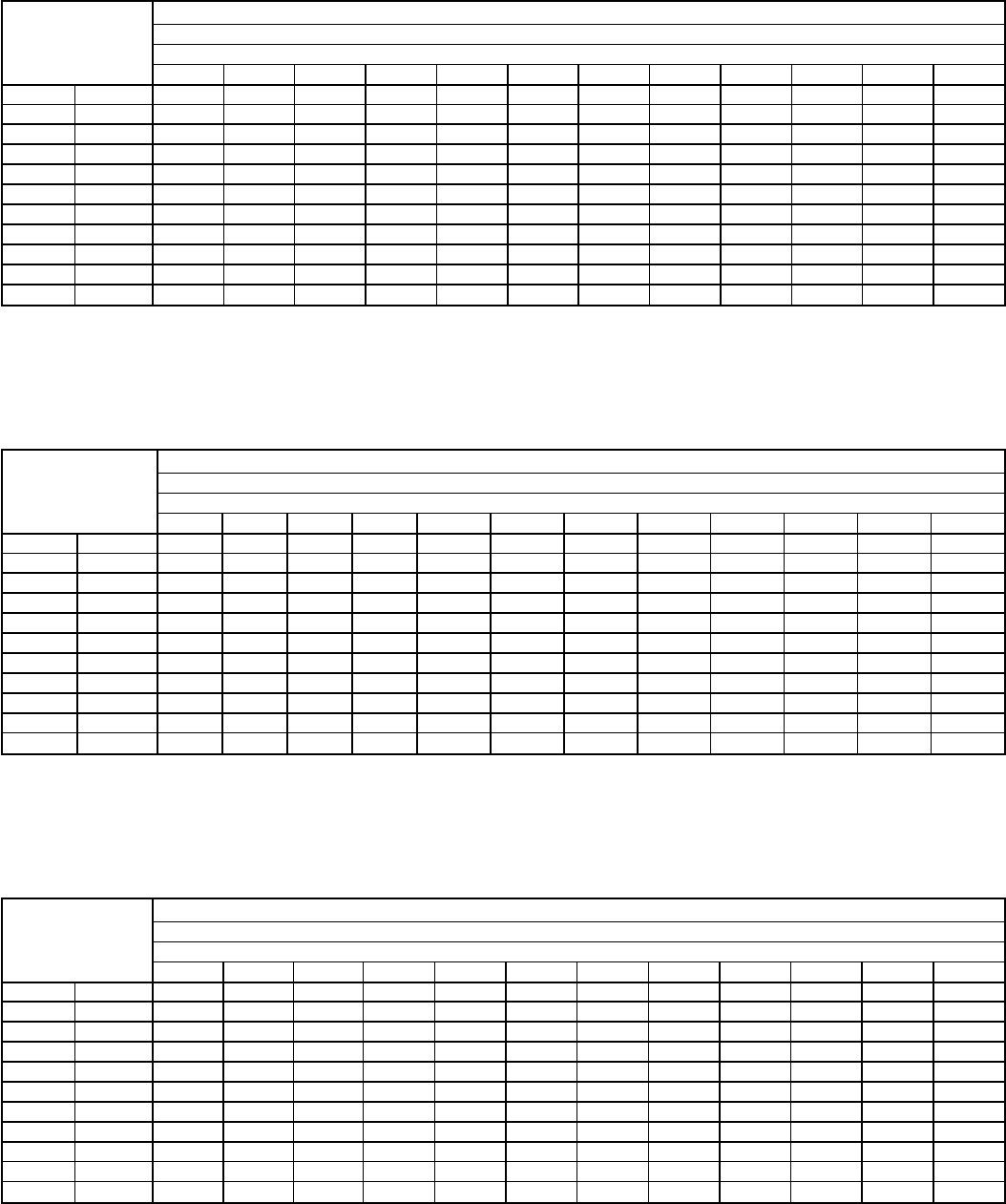
Table 8C — Superheat Charging Table, 588A030
TEMP (F)
OUTDOOR
ENTERING
AIR
INDOOR AIR — CFM
1000
Indoor Air — Ewb (F)
54 56 58 60 62 64 66 68 70 72 74 76
65 SPH 14.2 15.1 16.1 17.1 19.2 21.3 23.3 24.7 25.9 27.2 27.8 28.5
70 SPH 13.6 14.1 14.6 15.0 17.1 19.2 21.3 22.8 24.2 25.7 26.3 26.9
75 SPH 13.0 13.0 13.0 13.0 15.1 17.2 19.2 20.9 22.6 24.2 24.8 25.4
80 SPH 10.9 11.0 11.0 10.9 13.6 16.1 18.7 20.1 21.4 22.7 23.6 24.4
85 SPH 8.9 8.9 8.9 8.9 12.0 15.1 18.2 19.2 20.2 21.2 22.4 23.5
90 SPH 8.3 8.4 8.4 8.3 10.9 13.6 16.2 17.7 19.2 20.8 21.6 22.5
95 SPH 7.8 7.8 7.8 7.8 9.9 12.0 14.1 16.1 18.2 20.2 20.9 21.7
100 SPH 7.3 7.3 7.3 7.3 9.3 11.4 13.6 15.6 17.6 19.7 20.2 20.7
105 SPH 6.7 6.7 6.7 6.7 8.8 10.9 13.0 15.0 17.1 19.1 19.4 19.8
110 SPH ****6.78.910.9 13.0 15.0 17.1 18.0 18.9
115 SPH *****6.88.910.9 13.0 15.0 16.5 18.0
LEGEND
Ewb — Entering Wet Bulb
SPH — Superheat at Compressor (F)
*Do not attempt to charge system under these conditions — refrigerant
slugging may occur.
Table 8D — Superheat Charging Table, 588A036
TEMP (F)
OUTDOOR
ENTERING
AIR
INDOOR AIR — CFM
1200
Indoor Air — Ewb (F)
54 56 58 60 62 64 66 68 70 72 74 76
65 SPH 8.4 8.4 8.4 8.4 12.5 16.7 18.7 20.7 22.0 23.4 24.8 26.1
70 SPH 5.0 5.0 5.0 5.0 9.0 13.1 15.9 18.6 20.0 21.3 22.7 24.0
75 SPH ****5.49.613.1 16.6 17.9 19.3 20.6 22.0
80 SPH **** * 6.010.3 14.5 15.9 17.3 18.6 20.0
85 SPH **** * * 7.512.5 13.9 15.2 16.5 17.9
90 SPH **** * * 5.410.4 12.5 14.6 16.8 18.8
95 SPH **** * * * 8.411.314.1 17.0 19.8
100 SPH **** * * * 6.410.0 13.5 17.1 20.7
105 SPH **** ****8.713.0 17.3 21.7
110 SPH **** ****9.312.4 15.6 18.7
115 SPH **** ****10.0 11.9 13.8 15.8
LEGEND
Ewb — Entering Wet Bulb
SPH — Superheat at Compressor (F)
*Do not attempt to charge system under these conditions — refrigerant
slugging may occur.
Table 8E — Superheat Charging Table, 588A042
TEMP (F)
OUTDOOR
ENTERING
AIR
INDOOR AIR — CFM
1400
Indoor Air — Ewb (F)
54 56 58 60 62 64 66 68 70 72 74 76
65 SPH 11.0 11.0 11.0 14.0 17.0 20.0 22.0 24.0 26.0 26.0 27.7 28.6
70 SPH 7.5 7.5 7.5 10.4 13.4 16.4 18.9 21.4 24.0 25.0 26.1 27.1
75 SPH * * * 6.9 9.9 12.9 15.9 18.9 21.9 23.2 24.4 25.7
80 SPH * * * 5.9 8.4 10.8 13.8 16.8 19.8 21.3 22.8 24.9
85 SPH * * * 5.0 6.9 8.8 11.8 14.8 17.8 19.5 21.1 22.8
90 SPH * * * * 6.0 6.8 10.2 13.7 17.3 18.6 20.0 21.4
95 SPH * * * * * 5.0 8.7 12.7 16.7 17.8 18.9 20.0
100 SPH ******6.510.5 14.6 16.4 18.2 20.0
105 SPH *******8.412.6 15.1 17.6 20.0
110 SPH *******8.012.0 14.2 16.4 18.6
115 SPH *******7.711.513.4 15.3 17.2
LEGEND
Ewb — Entering Wet Bulb
SPH — Superheat at Compressor (F)
*Do not attempt to charge system under these conditions — refrigerant
slugging may occur.
—37—

Table 8F — Superheat Charging Table, 588A048 (Carrier Scroll Compressor)
TEMP (F)
OUTDOOR
ENTERING
AIR
INDOOR AIR — CFM
1600
Indoor Air — Ewb (F)
54 56 58 60 62 64 66 68 70 72 74 76
65 SPH 15.5 15.5 15.6 15.6 17.6 19.6 21.6 22.8 24.0 25.2 25.2 25.3
70 SPH 11.7 11.8 11.8 11.8 13.9 16.0 18.0 20.1 22.2 24.3 24.3 24.3
75 SPH 8.0 8.0 8.0 8.0 10.2 12.3 14.5 17.4 20.4 23.3 23.3 23.3
80 SPH 6.0 6.0 6.0 6.0 8.7 11.3 13.9 16.3 18.6 20.9 21.5 22.0
85 SPH ****7.210.3 13.4 15.1 16.8 18.5 19.7 20.8
90 SPH ****5.67.79.912.4 15.0 17.6 18.7 19.8
95 SPH *****5.26.39.813.2 16.7 17.7 18.8
100 SPH ******5.89.112.5 15.8 17.1 18.4
105 SPH ******5.28.411.714.9 16.5 18.1
110 SPH ******6.28.811.414.0 15.9 17.8
115 SPH ******7.19.111.113.1 15.3 17.5
LEGEND
Ewb — Entering Wet Bulb
SPH — Superheat at Compressor (F)
*Do not attempt to charge system under these conditions — refrigerant
slugging may occur.
Table 8G — Superheat Charging Table, 588A048 (Copeland Scroll Compressor)
TEMP (F)
OUTDOOR
ENTERING
AIR
INDOOR AIR — CFM
1600
Indoor Air — Ewb (F)
54 56 58 60 62 64 66 68 70 72 74 76
65 SPH 19.0 19.0 19.0 19.0 21.7 24.3 26.0 27.7 27.9 28.2 28.4 28.6
70 SPH 15.4 15.4 15.4 15.4 18.1 20.8 22.5 24.1 25.1 26.1 27.1 28.1
75 SPH 11.9 11.9 11.9 11.9 14.6 17.2 18.9 20.6 22.3 24.0 25.8 27.5
80 SPH 8.4 8.4 8.4 8.4 11.0 13.7 15.4 17.0 19.5 22.0 24.5 27.0
85 SPH 5.0 5.0 5.0 5.0 7.5 10.1 11.8 13.5 16.7 20.0 23.2 26.4
90 SPH *****6.69.011.414.7 17.9 21.1 24.4
95 SPH ******6.29.412.6 15.9 19.1 22.3
100 SPH *******7.310.6 13.8 17.0 20.3
105 SPH *******5.38.511.815.0 18.2
110 SPH ********6.911.215.5 19.8
115 SPH ********5.310.6 16.0 21.3
LEGEND
Ewb — Entering Wet Bulb
SPH — Superheat at Compressor (F)
*Do not attempt to charge system under these conditions — refrigerant
slugging may occur.
Table 8H — Superheat Charging Table, 588A060
TEMP (F)
OUTDOOR
ENTERING
AIR
INDOOR AIR — CFM
1995
Indoor Air — Ewb (F)
54 56 58 60 62 64 66 68 70 72 74 76
65 SPH 20.1 20.1 20.1 20.1 20.1 20.1 22.6 25.2 25.6 26.1 26.6 27.0
70 SPH 16.5 16.5 16.5 16.5 17.3 18.0 20.6 23.1 24.0 24.8 25.6 26.5
75 SPH 13.0 13.0 13.0 13.0 14.5 16.0 18.5 21.1 22.3 23.5 24.7 25.9
80 SPH 10.9 10.9 10.9 10.9 12.4 13.9 16.5 19.0 20.6 22.2 23.8 25.4
85 SPH 8.9 8.9 8.9 8.9 10.4 11.9 14.4 17.0 18.9 20.9 22.9 24.9
90 SPH 6.9 6.9 6.9 6.9 8.4 9.9 12.4 14.9 17.3 19.6 22.0 24.3
95 SPH 5.0 5.0 5.0 5.0 6.3 7.8 10.3 12.9 15.6 18.3 21.1 23.8
100 SPH *****5.88.310.8 13.9 17.0 20.1 23.2
105 SPH ******6.28.812.3 15.7 19.2 22.7
110 SPH *******6.710.6 14.4 18.3 22.2
115 SPH ********8.913.1 17.4 21.6
LEGEND
Ewb — Entering Wet Bulb
SPH — Superheat at Compressor (F)
*Do not attempt to charge system under these conditions — refrigerant
slugging may occur.
—38—
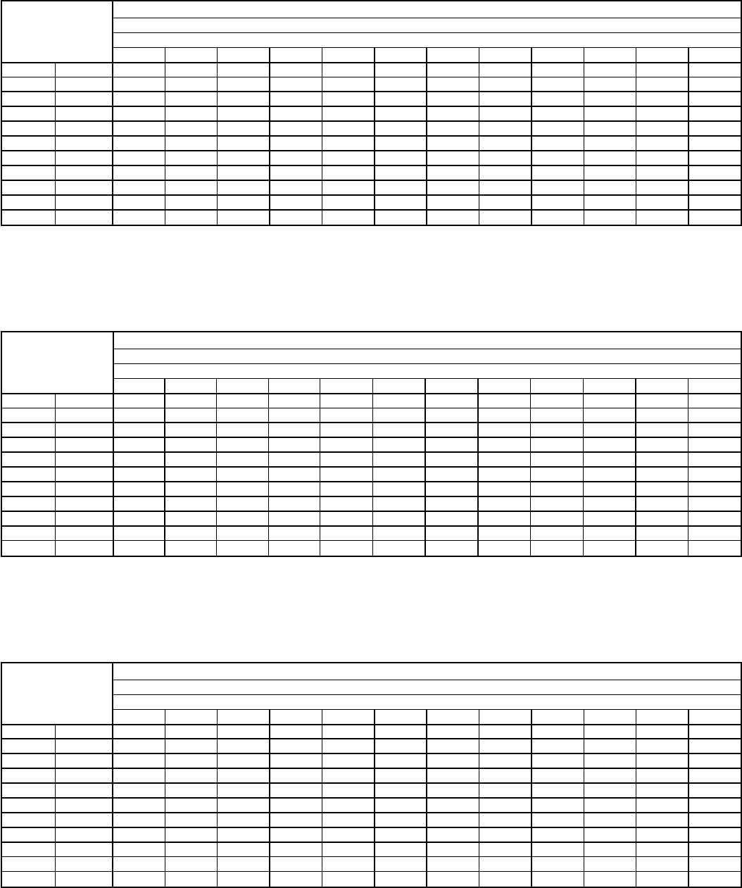
Table 9A — Superheat Charging Table, 589A024
TEMP (F)
OUTDOOR
ENTERING
AIR
INDOOR AIR — CFM
800
Indoor Air — Ewb (F)
54 56 58 60 62 64 66 68 70 72 74 76
65 SPH 22.1 22.1 22.8 23.2 25.3 27.4 29.5 29.8 30.2 30.5 31.3 32.1
70 SPH 18.5 18.9 19.3 19.6 22.2 24.8 27.5 28.3 29.1 30.0 30.0 30.0
75 SPH 15.0 15.4 15.7 16.1 19.2 22.3 25.4 26.7 28.1 29.4 28.7 28.0
80 SPH 9.2 9.5 9.7 9.9 14.4 18.9 23.3 24.7 26.0 27.3 27.4 27.4
85 SPH ****9.615.5 21.3 22.6 24.0 25.3 26.1 26.8
90 SPH ****7.212.5 17.8 20.1 22.4 24.8 25.1 25.5
95 SPH *****9.414.2 17.5 20.9 24.2 24.2 24.2
100 SPH *****7.110.6 14.5 18.3 22.1 22.9 23.6
105 SPH ******7.111.415.8 20.1 21.6 23.1
110 SPH *******8.413.2 18.0 19.5 21.0
115 SPH *******5.310.7 16.0 17.5 19.0
LEGEND
Ewb — Entering Wet Bulb
SPH — Superheat at Compressor (F)
*Do not attempt to charge system under these conditions — refrigerant
slugging may occur.
Table 9B — Superheat Charging Table, 589A030
TEMP (F)
OUTDOOR
ENTERING
AIR
INDOOR AIR — CFM
1000
Indoor Air — Ewb (F)
54 56 58 60 62 64 66 68 70 72 74 76
65 SPH 11.2 11.2 11.2 11.2 14.9 18.6 22.3 22.4 22.5 22.7 22.9 23.1
70 SPH 7.6 7.7 7.7 7.7 12.1 16.6 21.1 21.6 22.0 22.4 22.5 22.5
75 SPH ****9.414.7 20.0 20.7 21.4 22.1 22.1 22.0
80 SPH ****8.513.5 18.5 19.3 20.2 21.0 21.6 22.1
85 SPH ****7.612.3 17.0 18.0 18.9 19.9 21.1 22.3
90 SPH *****10.0 14.2 16.0 17.8 19.6 20.7 21.8
95 SPH *****7.711.514.1 16.7 19.2 20.2 21.2
100 SPH * * * * * * 5.7 9.9 14.0 18.2 19.4 20.6
105 SPH *******5.711.417.1 18.6 20.1
110 SPH ********8.913.5 15.8 18.0
115 SPH *********10.0 13.0 16.0
LEGEND
Ewb — Entering Wet Bulb
SPH — Superheat at Compressor (F)
*Do not attempt to charge system under these conditions — refrigerant
slugging may occur.
Table 9C — Superheat Charging Table, 589A036
TEMP (F)
OUTDOOR
ENTERING
AIR
INDOOR AIR — CFM
1200
Indoor Air — Ewb (F)
54 56 58 60 62 64 66 68 70 72 74 76
65 SPH 21.3 21.3 21.3 21.3 22.0 22.6 23.3 23.5 23.7 23.8 23.3 22.8
70 SPH 19.3 19.3 19.3 19.3 20.2 21.2 22.2 22.3 22.5 22.6 22.0 21.5
75 SPH 17.2 17.2 17.2 17.2 18.5 19.7 21.0 21.1 21.3 21.4 20.7 20.1
80 SPH 13.6 13.6 13.6 13.6 15.1 16.6 18.0 18.5 18.9 19.3 19.4 19.5
85 SPH 10.1 10.1 10.1 10.1 11.7 13.4 15.0 15.8 16.5 17.3 18.1 19.0
90 SPH 6.5 6.5 6.5 6.5 8.8 11.2 13.5 14.6 15.7 16.8 17.2 17.6
95 SPH ****6.09.012.0 13.4 14.8 16.2 16.2 16.2
100 SPH ******6.08.711.414.1 14.9 15.6
105 SPH ********8.012.1 13.6 15.1
110 SPH *********10.0 11.5 13.0
115 SPH *********8.09.511.0
LEGEND
Ewb — Entering Wet Bulb
SPH — Superheat at Compressor (F)
*Do not attempt to charge system under these conditions — refrigerant
slugging may occur.
—39—
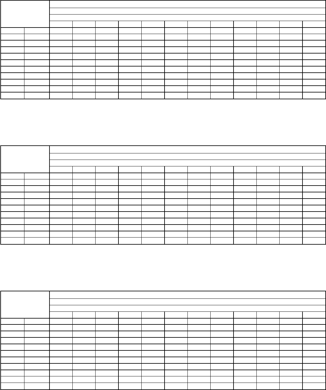
Table 9D — Superheat Charging Table, 589A042
TEMP (F)
OUTDOOR
ENTERING
AIR
INDOOR AIR — CFM
1400
Indoor Air — Ewb (F)
54 56 58 60 62 64 66 68 70 72 74 76
65 SPH 23.9 23.9 23.9 23.9 24.4 24.9 25.5 25.8 26.1 26.5 25.6 24.7
70 SPH 21.9 21.9 21.9 21.9 22.4 22.9 23.4 23.7 24.1 24.5 24.0 23.5
75 SPH 19.8 19.8 19.8 19.8 20.3 20.8 21.3 21.7 22.0 22.4 22.4 22.4
80 SPH 16.3 16.3 16.3 16.3 17.9 19.6 21.3 21.5 21.7 21.8 21.8 21.8
85 SPH 12.7 12.7 12.7 12.7 15.6 18.4 21.3 21.3 21.3 21.3 21.3 21.3
90 SPH 9.2 9.2 9.2 9.2 12.0 14.9 17.8 18.7 19.7 20.8 20.8 20.8
95 SPH 5.6 5.6 5.6 5.6 8.5 11.3 14.2 16.2 18.2 20.2 20.2 20.2
100 SPH *****8.010.6 13.1 15.6 18.1 18.9 19.6
105 SPH ******7.110.1 13.1 16.1 17.6 19.1
110 SPH *******7.010.5 14.0 15.5 17.0
115 SPH ********8.012.0 13.5 15.0
LEGEND
Ewb — Entering Wet Bulb
SPH — Superheat at Compressor (F)
*Do not attempt to charge system under these conditions — refrigerant
slugging may occur.
Table 9E — Superheat Charging Table, 589A048
TEMP (F)
OUTDOOR
ENTERING
AIR
INDOOR AIR — CFM
1600
Indoor Air — Ewb (F)
54 56 58 60 62 64 66 68 70 72 74 76
65 SPH 27.2 27.2 27.2 27.2 27.0 26.7 26.5 26.0 25.6 25.1 24.5 24.0
70 SPH 25.0 25.0 25.0 25.0 24.8 24.6 24.5 24.5 24.5 24.6 23.8 23.1
75 SPH 22.8 22.8 22.8 22.8 22.7 22.5 22.4 22.9 23.5 24.0 23.1 22.2
80 SPH 20.6 20.6 20.6 20.6 20.5 20.4 20.3 21.4 22.4 23.5 22.4 21.4
85 SPH 18.3 18.3 18.3 18.3 18.3 18.3 18.3 19.8 21.4 22.9 21.8 20.6
90 SPH 13.3 13.3 13.3 13.3 14.2 15.2 16.3 17.8 19.3 20.9 20.4 19.9
95 SPH 8.2 8.2 8.2 8.2 10.2 12.2 14.2 15.7 17.3 18.8 19.0 19.2
100 SPH ****6.38.410.6 12.9 15.2 17.5 18.1 18.7
105 SPH ******7.110.1 13.1 16.1 17.1 18.2
110 SPH *******7.110.5 14.0 15.3 16.6
115 SPH ********8.012.0 13.5 15.0
LEGEND
Ewb — Entering Wet Bulb
SPH — Superheat at Compressor (F)
*Do not attempt to charge system under these conditions — refrigerant
slugging may occur.
Table 9F — Superheat Charging Table, 589A060
TEMP (F)
OUTDOOR
ENTERING
AIR
INDOOR AIR — CFM
1995
Indoor Air — Ewb (F)
54 56 58 60 62 64 66 68 70 72 74 76
65 SPH 20.1 20.1 20.1 20.1 20.1 20.1 22.6 25.2 25.6 26.1 26.6 27.0
70 SPH 16.5 16.5 16.5 16.5 17.3 18.0 20.6 23.1 24.0 24.8 25.6 26.5
75 SPH 13.0 13.0 13.0 13.0 14.5 16.0 18.5 21.1 22.3 23.5 24.7 25.9
80 SPH 10.9 10.9 10.9 10.9 12.4 13.9 16.5 19.0 20.6 22.2 23.8 25.4
85 SPH 8.9 8.9 8.9 8.9 10.4 11.9 14.4 17.0 18.9 20.9 22.9 24.9
90 SPH 6.9 6.9 6.9 6.9 8.4 9.9 12.4 14.9 17.3 19.6 22.0 24.3
95 SPH 5.0 5.0 5.0 5.0 6.3 7.8 10.3 12.9 15.6 18.3 21.1 23.8
100 SPH *****5.88.310.8 13.9 17.0 20.1 23.2
105 SPH ******6.28.812.3 15.7 19.2 22.7
110 SPH *******6.710.6 14.4 18.3 22.2
115 SPH ********8.913.1 17.4 21.6
LEGEND
Ewb — Entering Wet Bulb
SPH — Superheat at Compressor (F)
*Do not attempt to charge system under these conditions — refrigerant
slugging may occur.
—40—
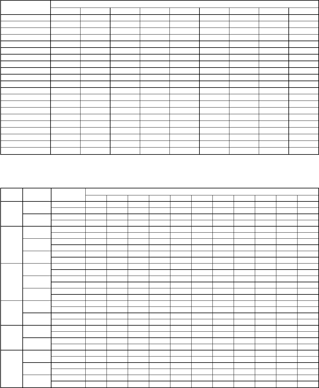
Table 10 — Required Suction-Tube Temperature (F)*
SUPERHEAT
TEMP (F) SUCTION PRESSURE AT SERVICE PORT (psig)
61.5 64.2 67.1 70.0 73.0 76.0 79.2 82.4 85.7
035 37 39 41 43 45 47 49 51
237 39 41 43 45 47 49 51 53
439 41 43 45 47 49 51 53 55
641 43 45 47 49 51 53 55 57
843 45 47 49 51 53 55 57 59
10 45 47 49 51 53 55 57 59 61
12 47 49 51 53 55 57 59 61 63
14 49 51 53 55 57 59 61 63 65
16 51 53 55 57 59 61 63 65 67
18 53 55 57 59 61 63 65 67 69
20 55 57 59 61 63 65 67 69 71
22 57 59 61 63 65 67 69 71 73
24 59 61 63 65 67 69 71 73 75
26 61 63 65 67 69 71 73 75 77
28 63 65 67 69 71 73 75 77 79
30 65 67 69 71 73 75 77 79 81
32 67 69 71 73 75 77 79 81 83
34 69 71 73 75 77 79 81 83 85
36 71 73 75 77 79 81 83 85 87
38 73 75 77 79 81 83 85 87 89
40 75 77 79 81 83 85 87 89 91
*Temperature at suction service valve.
Table 11 — Dry-Coil Air Delivery* — Horizontal Discharge at 230 and 460 V — Unit 588A
(Deduct 10% from Cfm and Watts for 208 V Operation)
UNIT
588A MOTOR
SPEED AIR
DELIVERY EXTERNAL STATIC PRESSURE (in. wg)
0.0 0.1 0.2 0.3 0.4 0.5 0.6 0.7 0.8 0.9 1.0
018
Low Watts 230 225 220 210 195 170 †††††
Cfm 760745725695640540†††††
High Watts ††††270235200††††
Cfm ††††850700450††††
024,
030
Low Watts 275 275 273 269 260 257 249 ††††
Cfm 857835802782745717663††††
Med Watts 371 368 360 349 345 326 319 304 293 † †
Cfm 1079 1063 1027 996 978 919 865 783 726 † †
High Watts 514 493 476 460 443 425 401 378 344 † †
Cfm 1409 1383 1324 1282 1223 1156 1068 984 857 † †
036
Low Watts 473 447 427 418 395 367 346 337 323 † †
Cfm 1253 1253 1172 1130 1047 946 865 829 768 † †
Med Watts 519 500 478 459 439 410 377 357 340 † †
Cfm 1414 1366 1287 1234 1162 1074 920 829 743 † †
High Watts 667 634 609 593 564 541 506 469 436 422 †
Cfm 1734 1639 1563 1461 1370 1292 1157 960 829 743 †
042
Low Watts 678 635 604 580 550 520 493 455 430 † †
Cfm 1540 1515 1475 1430 1375 1280 1225 1128 1020 † †
High Watts † 820 785 750 700 680 649 612 570 † †
Cfm † 1825 1750 1685 1610 1525 1485 1355 1215 † †
048
Low Watts † † 854 786 744 706 641 606 557 511 †
Cfm † † 2026 1905 1830 1752 1603 1513 1367 1228 †
High Watts † † † 905 846 824 804 748 683 637 †
Cfm † † † 2025 1905 1830 1752 1603 1398 1228 †
060
Low Watts 1104 1093 1072 1029 986 938 891 830 769 733 697
Cfm 1876 1865 1840 1803 1765 1710 1641 1533 1425 1345 1264
Med Watts 1351 1295 1245 1197 1148 1096 1053 994 936 871 812
Cfm 2249 2209 2157 2097 2036 1959 1882 1781 1679 1542 1405
High Watts † † 1391 1343 1296 1247 1191 1129 1067 1002 936
Cfm † † 2299 2231 2152 2060 1975 1859 1746 1591 1441
*Air delivery values are without air filter and are for dry coil. See
Table 17 for wet coil pressure drop. Deduct field-supplied air filter pres-
sure drop and wet coil pressure drop to obtain external static pressure
available for ducting.
†Unit air delivery is outside of operating range.
NOTE: Do not operate the unit at a cooling airflow that is less than
350 cfm for each 12,000 Btuh of rated cooling capacity. Evaporator-coil
icing may occur at airflows below this point. Water blow-off may occur at
airflows above 450 cfm per 12,000 Btuh of rated cooling
capacity.
—41—
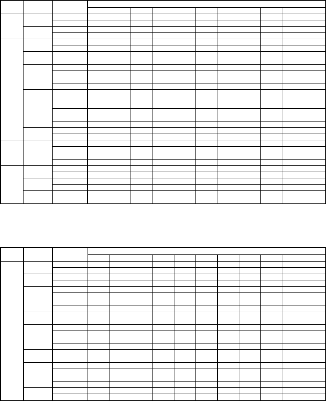
Table 12 — Dry-Coil Air Delivery* — Downflow Discharge at 230 and 460 V — Unit 588A
(Deduct 10% from Cfm and Watts for 208 V Operation)
UNIT
588A MOTOR
SPEED AIR
DELIVERY EXTERNAL STATIC PRESSURE (in. wg)
0.0 0.1 0.2 0.3 0.4 0.5 0.6 0.7 0.8 0.9 1.0
018
Low Watts † 295 251 223 201 176 149 124 † † †
Cfm † 821 817 753 665 536 343 164 † † †
High Watts 401 376 346 322 294 272 250 229 219 † †
Cfm 1334 1253 1128 996 816 658 461 246 167 † †
024,
030
Low Watts † 285 284 282 278 274 270 261 251 244 230
Cfm † 798 761 727 682 634 581 525 450 371 304
Med Watts † 378 371 368 362 357 343 332 315 301 283
Cfm † 1011 982 948 906 858 771 703 597 492 387
High Watts † 520 511 487 472 451 431 411 385 362 341
Cfm † 1342 1309 1237 1181 1106 1007 892 745 610 471
036
Low Watts † 460 439 423 398 379 349 322 297 270 246
Cfm † 1191 1136 1081 1005 907 795 687 579 471 349
Med Watt † 511 492 470 450 420 392 364 332 308 275
Cfm † 1316 1244 1178 1104 1005 891 784 657 535 389
High Watts † 655 631 603 584 552 522 492 459 433 398
Cfm † 1541 1458 1367 1292 1178 1053 920 806 662 509
042
Low Watts † 637 612 587 560 526 493 455 † † †
Cfm † 1500 1450 1405 1350 1290 1200 1105 † † †
High Watts † 790 750 700 679 639 608 574 547 † †
Cfm † 1750 1675 1604 1509 1421 1323 1221 1094 † †
048
Low Watts † 847 784 746 708 646 609 563 516 † †
Cfm † 1995 1901 1822 1730 1580 1477 1319 1178 † †
High Watts † † 909 852 820 801 751 687 639 † †
Cfm † † 2018 1896 1814 1729 1582 1380 1270 † †
060
Low Watts † 983 950 923 885 845 804 751 697 665 633
Cfm † 1838 1808 1755 1702 1628 1553 1446 1339 1257 1175
Med Watts † 1115 1083 1045 1006 964 921 872 823 783 742
Cfm † 2067 2023 1957 1891 1807 1723 1612 1501 1392 1282
High Watts † 1284 1201 1166 1131 1092 1053 1001 950 907 864
Cfm † 2167 2108 2038 1968 1882 1796 1676 1555 1437 1318
*Air delivery values are without air filter and are for dry coil. See
Table 17 for wet coil pressure drop. Deduct field-supplied air filter
pressure drop and wet coil pressure drop to obtain external static
pressure available for ducting.
†Unit air delivery is outside of operating range.
NOTE: Do not operate the unit at a cooling airflow that is less than
350 cfm for each 12,000 Btuh of rated cooling capacity. Evaporator-
coil icing may occur at airflows below this point. Water blow-off may
occur at airflows above 450 cfm per 12,000 Btuh of rated cooling
capacity.
Table 13 — Dry-Coil Air Delivery* — Horizontal Discharge at 230 and 460 V — Unit 589A
(Deduct 10% from Cfm and Watts for 208 V Operation)
UNIT
589A MOTOR
SPEED AIR
DELIVERY EXTERNAL STATIC PRESSURE (in. wg)
0.0 0.1 0.2 0.3 0.4 0.5 0.6 0.7 0.8 0.9 1.0
024,
030
Low Watts 280 275 265 255 250 245 240 ††††
Cfm 820810755700660600560††††
Med Watts 365 360 350 345 340 330 320 310 300 † †
Cfm 1025 1010 975 940 900 850 800 720 630 † †
High Watts † † 490 480 470 460 445 430 410 390 380
Cfm † † 1300 1255 1200 1150 1080 1005 915 790 620
036
Low Watts 520 495 474 458 445 425 †††††
Cfm 1375 1335 1290 1240 1200 1140 †††††
Med Watts 575 560 535 510 480 460 440 425 † † †
Cfm 1520 1490 1450 1400 1380 1300 1200 1080 † † †
High Watts ††††650614575540510480†
Cfm ††††1560 1500 1380 1280 1170 1060 †
042
Low Watts 490 480 470 460 450 430 410 390 † † †
Cfm 1400 1380 1340 1300 1250 1200 1140 1070 † † †
Med Watts 590 580 560 545 525 505 480 450 420 † †
Cfm 1600 1560 1540 1470 1430 1360 1300 1220 1120 † †
High Watts †††††700670640600560500
Cfm †††††1780 1670 1600 1480 1340 1100
048**
Low Watts 1050 1000 970 930 870 810 750 680 600 † †
Cfm 1850 1830 1800 1785 1750 1700 1640 1500 1330 † †
High Watts † † † 1050 1000 930 870 810 740 665 †
Cfm † † † 2000 1940 1850 1750 1635 1500 1300 †
*Air delivery values are without air filter and are for dry coil. See
Table 17 for wet coil pressure drop. Deduct field-supplied air filter
pressure drop and wet coil pressure drop to obtain external static
pressure available for ducting.
†Unit air delivery is outside of operating range.
**For 460 v units only.
NOTE: Do not operate the unit at a cooling airflow that is less than
350 cfm for each 12,000 Btuh of rated cooling capacity. Evaporator-
coil icing may occur at airflows below this point. Water blow-off may
occur at airflows above 450 cfm per 12,000 Btuh of rated cooling
capacity.
—42—
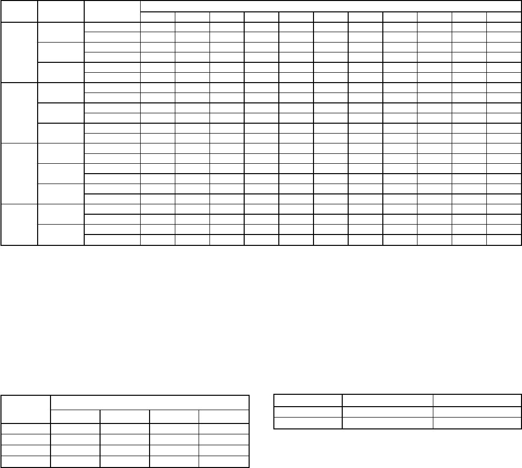
Table 14 — Dry-Coil Air Delivery* — Downflow Discharge at 230 and 460 V — Unit 589A
(Deduct 10% from Cfm and Watts for 208 V Operation)
UNIT
589A MOTOR
SPEED AIR
DELIVERY EXTERNAL STATIC PRESSURE (in. wg)
0.0 0.1 0.2 0.3 0.4 0.5 0.6 0.7 0.8 0.9 1.0
024,
030
Low Watts 280 275 265 255 250 245 240 ††††
Cfm 820810755700660600560††††
Med Watts 365 360 350 345 340 330 320 310 300 † †
Cfm 1025 1010 975 940 900 850 800 720 630 † †
High Watts † † 490 480 470 460 445 430 410 390 380
Cfm † † 1300 1255 1200 1150 1080 1005 915 790 620
036
Low Watts 520 495 474 458 445 425 †††††
Cfm 1375 1335 1290 1240 1200 1140 †††††
Med Watts 575 560 535 510 480 460 440 425 † † †
Cfm 1520 1490 1450 1400 1380 1300 1200 1080 † † †
High Watts ††††650614575540510480†
Cfm ††††1560 1500 1380 1280 1170 1060 †
042
Low Watts 490 480 470 460 450 430 410 390 † † †
Cfm 1400 1380 1340 1300 1250 1200 1140 1070 † † †
Med Watts 590 580 560 545 525 505 480 450 420 † †
Cfm 1600 1560 1540 1470 1430 1360 1300 1220 1120 † †
High Watts †††††700670640600560500
Cfm †††††1780 1670 1600 1480 1340 1100
048**
Low Watts 1050 1000 970 930 870 810 750 680 600 † †
Cfm 1850 1830 1800 1785 1750 1700 1640 1500 1330 † †
High Watts † † † 1050 1000 930 870 810 740 665 †
Cfm † † † 2000 1940 1850 1750 1635 1500 1300 †
*Air delivery values are without air filter and are for dry coil. See
Table 17 for wet coil pressure drop. Deduct field-supplied air filter pres-
sure drop and wet coil pressure drop to obtain external static pressure
available for ducting.
†Unit air delivery is outside of operating range.
**For 460 v units only.
NOTE: Do not operate the unit at a cooling airflow that is less than 350
cfm for each 12,000 Btuh of rated cooling capacity. Evaporator-coil icing
may occur at airflows below this point. Water blow-off may occur at air-
flows above 450 cfm per 12,000 Btuh of rated cooling capacity.
Table 15 — Dry Coil Air Delivery* — Heating —
Horizontal and Downflow Discharge for Integrated Control
Motor Units at 230-V (Deduct 10% from Cfm for 208-V
Operation)
HEATING
INPUT
(Btuh)
EASY SELECT BOARD TERMINALS (Cfm)
1234
80,000 1300 1400 1600 1750
100,000 — 1400 1600 1750
95,000 — — 1600 1750
136,000 — — — 1750
*Air delivery values are for dry coil at 230 v. Airflow is independent of
external static pressure within 65% of table values up to 0.8 in wg.
NOTES:
1. Dashed areas do not fall within approved range.
2. The above values occur with the AC/HP CFM ADJUST select jumper
set on MED.
3. Airflow can be adjusted 110% or −10% by selecting HI or LO for all
modes except FAN ONLY.
Table 16 — Dry-Coil Air Delivery* — Fan Only and Cooling
— Horizontal and Downflow Discharge for Integrated Con-
trol Motor Units at 230-V (Deduct 10% from Cfm for 208-V
Operation)
UNIT 589A FAN ONLY (Cfm) COOLING (Cfm)
048 1400 1600
060 1750 2000
*Air delivery values are for dry coil at 230 v. Airflow is independent of
external static pressure within 65% of table values up to 0.8 in wg.
NOTE: Do not operate the unit at a cooling airflow that is less than
350 cfm for each 12,000 Btuh of rated cooling capacity. Evaporator-coil
icing may occur at airflows below this point. Water blow-off may occur at
airflows above 450 cfm per 12,000 Btuh of rated cooling capacity.
—43—
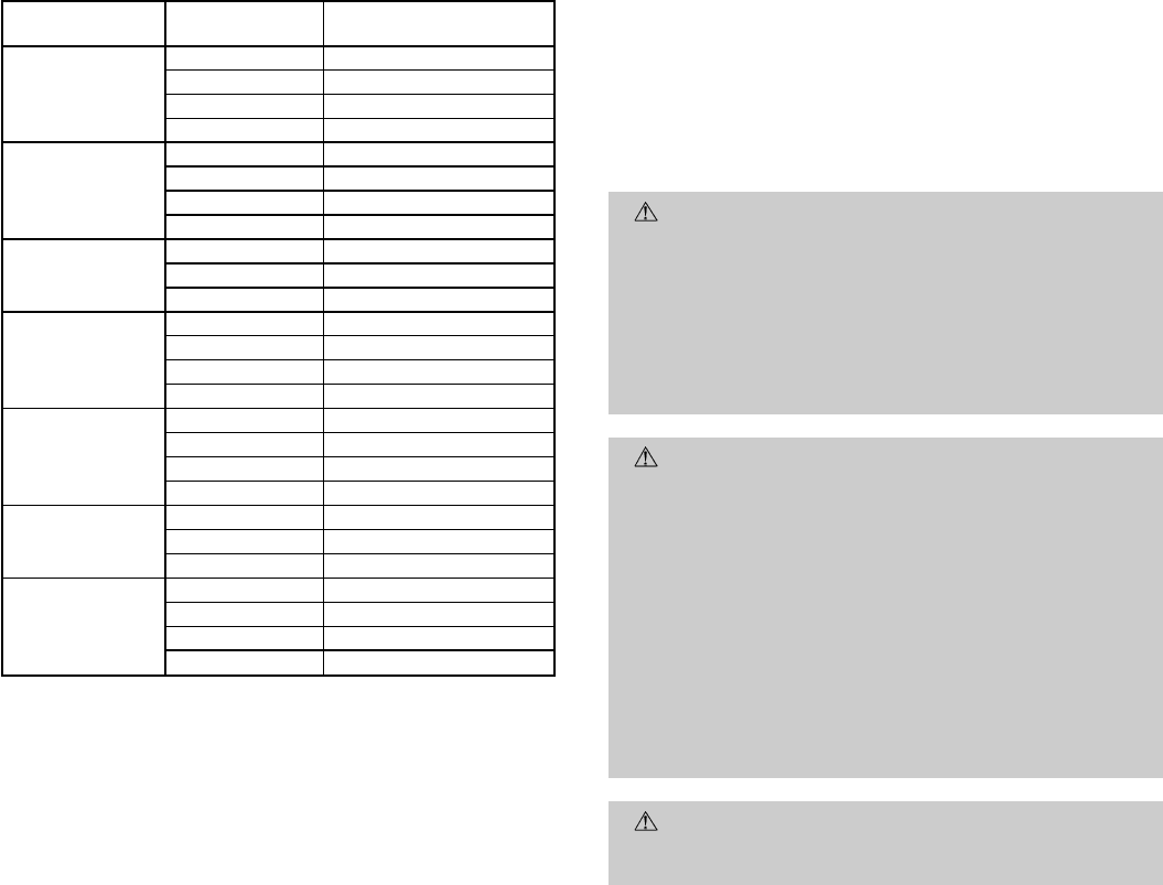
Table 17 — Wet Coil Pressure Drop
UNIT SIZE AIRFLOW
(cfm) PRESSURE DROP
(in. wg)
018*
600 0.069
700 0.082
800 0.102
900 0.116
024
600 0.039
700 0.058
800 0.075
900 0.088
030
900 0.088
1000 0.095
1200 0.123
036
1000 0.068
1200 0.088
1400 0.108
1600 0.123
042
1000 0.048
1200 0.069
1400 0.088
1600 0.102
048
1400 0.068
1600 0.075
1800 0.088
060
1700 0.082
1900 0.095
2100 0.108
2300 0.123
*Unit 588A only.
D. Cooling Sequence of Operation
With the room thermostat SYSTEM switch in the COOL po-
sition and the FAN switch in the AUTO. position, the cooling
sequence of operation is as follows:
When the room temperature rises to a point that is slightly
above the cooling control setting of the thermostat, the ther-
mostat completes the circuit between thermostat terminal R
to terminals Y and G. These completed circuits through the
thermostat connect contactor coil (C) (through unit wire Y)
and blower relay coil (BR) (through unit wire G) across the
24-v secondary of transformer (TRAN).
NOTE: The blower relay coil (BR) is used on standard non-
ICM units, ICM units use evaporator (indoor) fan on (IFO)
connection.
The normally-open contacts of energized contactor (C) close
and complete the circuit through compressor motor (COMP)
to condenser (outdoor) fan motor (OFM). Both motors start
instantly.
On standard non-ICM units, the set of normally-open con-
tacts of energized relay BR close and complete the circuit
through evaporator blower (indoor) fan motor (IFM). On ICM
units, the IFO completes the circuit through evaporator blower
IFM. The blower motor starts instantly.
NOTE: Once the compressor has started and then has stopped,
it should not be started again until 5 minutes have elapsed.
The cooling cycle remains ‘‘on’’ until the room temperature
drops to point that is slightly below the cooling control set-
ting of the room thermostat. At this point, the thermostat
‘‘breaks’’ the circuit between thermostat terminal R to termi-
nals Y and G. These open circuits deenergize contactor coil C
and relay coil BR. The condenser and compressor motors stop.
After a 30-second delay, the blower motor stops. The unit is
in a ‘‘standby’’ condition, waiting for the next ‘‘call for cool-
ing’’ from the room thermostat.
MAINTENANCE
To ensure continuing high performance, and to minimize the
possibility of premature equipment failure, periodic mainte-
nance must be performed on this equipment. This combina-
tion heating/cooling unit should be inspected at least once each
year by a qualified service person. To troubleshoot heating or
cooling of units, refer to tables at the back of the book.
NOTE TO EQUIPMENT OWNER: Consult your local dealer
about the availability of a maintenance contract.
WARNING: The ability to properly perform mainte-
nance on this equipment requires certain expertise, me-
chanical skills, tools, and equipment. If you do not pos-
sess these, do not attempt to perform any maintenance
on this equipment other than those procedures recom-
mended in the User’s Manual. FAILURE TO HEED THIS
WARNING COULD RESULT IN SERIOUS PERSONAL
INJURY AND POSSIBLE DAMAGE TO THIS
EQUIPMENT.
WARNING: Failure to follow these warnings could re-
sult in serious personal injury:
1. Turn off gas supply, then turn off electrical power to
the unit before performing any maintenance or serv-
ice on the unit.
2. Use extreme caution when removing panels and parts.
As with any mechanical equipment, personal injury
can result from sharp edges, etc.
3. Never place anything combustible either on, or in con-
tact with, the unit.
4. Should overheating occur, or the gas supply fail to
shut off, shut off the external main manual gas valve
to the unit, then shut off the electrical supply.
CAUTION: Errors made when reconnecting wires may
cause improper and dangerous operation. Label all wires
prior to disconnection when servicing.
The minimum maintenance requirements for this equipment
are as follows:
1. Inspect air filter(s) each month. Clean or replace when
necessary.
2. Inspect indoor coil, drain pan, and condensate drain each
cooling season for cleanliness. Clean when necessary.
3. Inspect blower motor and wheel for cleanliness and check
lubrication each heating and cooling season. Clean and
lubricate (if required) when necessary. For first heating
season, inspect blower wheel bimonthly to determine
proper cleaning frequency.
4. Check electrical connections for tightness and controls
for proper operation each heating and cooling season.
Service when necessary.
5. Check and inspect heating section before each heating
season. Clean and adjust when necessary.
6. Check flue hood screen and remove any obstructions if
necessary.
7. Check vent screen and clean if necessary.
—44—
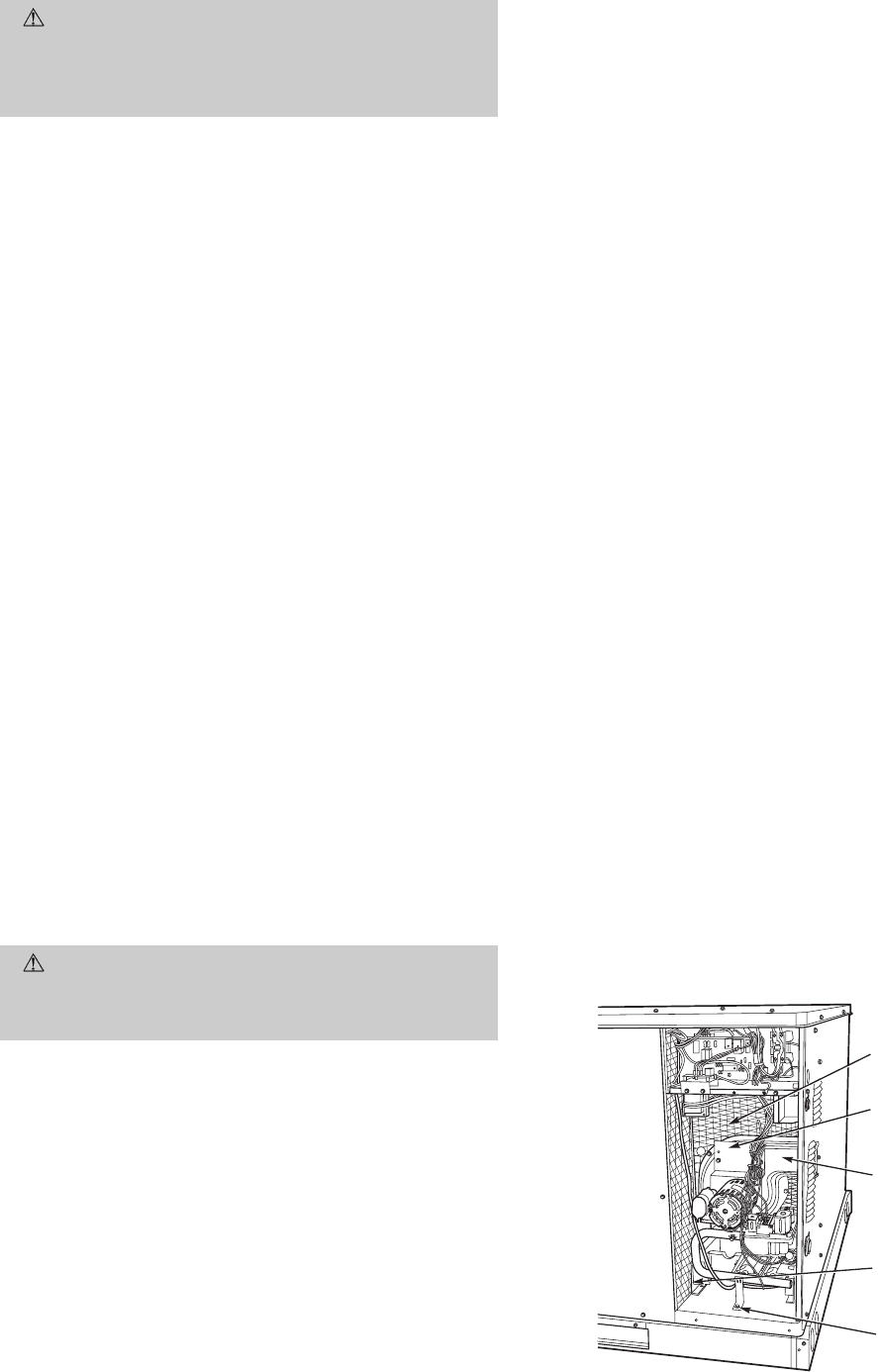
I. AIR FILTER
CAUTION: Never operate the unit without a suit-
able air filter in the return-air duct system. Always re-
place the filter with the same dimensional size and type
as originally installed. See Tables 1 and 2 for recom-
mended filter sizes.
Inspect air filter(s) at least once each month and replace
(throwaway-type) or clean (cleanable-type) at least twice dur-
ing each heating and cooling season or whenever the filter(s)
becomes clogged with dust and lint.
II. UNIT TOP REMOVAL
NOTE: When performing maintenance or service procedures
that require removal of the unit top, be sure to perform all of
the routine maintenance procedures that require top re-
moval, including: inspection of the heat exchanger area, coil
inspection and cleaning, and condensate drain pan inspec-
tion and cleaning.
Only qualified service personnel should perform mainte-
nance and service procedures that require unit top removal.
Refer to the following top removal procedures:
1. Turn off gas supply, then turn off electric power to unit.
2. Remove all screws that secure unit top, including screws
around 4 sides and those on top that screw into internal
divider panels. Save all screws.
3. Lift top from unit carefully. Set top on edge.
4. Carefully replace and secure unit top to unit, using screws
removed in Step 2, when maintenance and/or service pro-
cedures are completed. (Be sure to use original screws
that have rubber washers to seal out water when secur-
ing top to internal divider panels.)
III. EVAPORATOR BLOWER AND MOTOR
NOTE: Motors without oilers are prelubricated. Do not at-
tempt to lubricate these motors.
For longer life, operating economy, and continuing efficiency,
clean accumulated dirt and grease from the blower wheel and
motor annually.
Lubricate the motor every 5 years if the motor is used inter-
mittently (thermostat FAN switch in AUTO. position), or ev-
ery 2 years if the motor is used continuously (thermostat FAN
switch in ON position).
WARNING: Turn off the gas supply, then disconnect
and tag electrical power to the unit before cleaning and
lubricating the blower motor and wheel. Failure to ad-
here to this warning could cause personal injury or death.
To clean and lubricate the blower motor and wheel:
1. Remove and disassemble blower assembly as follows:
a. Remove blower access door.
b. On standard non-ICM units disconnect motor lead from
blower relay (BR). Disconnect yellow lead from ter-
minal L2 of the contactor.
c. On all units remove blower assembly from unit. Re-
move screws securing blower to gas partition and slide
assembly out. Be careful not to tear insulation in blower
compartment.
d. Ensure proper reassembly by marking blower wheel
and motor in relation to blower housing before dis-
assembly.
e. Loosen setscrew(s) that secures wheel to motor shaft,
remove screws that secure motor mount brackets to
housing, and slide motor and motor mount out of
housing.
2. Lubricate motor as follows:
a. Thoroughly clean all accumulations of dirt or grease
from motor housing.
b. Remove dust caps or plugs from oil ports located at
each end of motor.
c. Use a good grade of SAE 20 nondetergent motor oil
and put one teaspoon (
3
⁄
16
oz. or 16 to 25 drops) in
each oil port.
d. Allow time for oil to be absorbed by each bearing, then
wipe excess oil from motor housing.
e. Replace dust caps or plugs in oil ports.
3. Remove and clean blower wheel as follows:
a. Ensure proper reassembly by marking wheel
orientation.
b. Lift wheel from housing. When handling and/or clean-
ing blower wheel, be sure not to disturb balance weights
(clips) on blower wheel vanes.
c. Remove caked-on dirt from wheel and housing with
a brush. Remove lint and/or dirt accumulations from
wheel and housing with vacuum cleaner, using soft
brush attachment. Remove grease and oil with mild
solvent.
d. Reassemble wheel into housing.
e. Reassemble motor into housing. Be sure setscrews are
tightened on motor shaft flats and not on round part
of shaft.
f. Reinstall blower access door.
4. Restore electrical power, then gas supply to unit. Start
unit and check for proper blower rotation and motor speeds
during heating and cooling cycles.
IV. FLUE GAS PASSAGEWAYS
To inspect the flue collector box and upper areas of the heat
exchanger:
1. Remove the combustion blower wheel and motor assem-
bly according to directions in Combustion-Air Blower sec-
tion on page 46.
2. Remove the 3 screws holding the blower housing to the
flue collector box cover (see Fig. 34).
3. Remove the 12 screws holding the flue collector box cover
(Fig. 34) to the heat exchanger assembly. Inspect the heat
exchangers.
4. Clean all surfaces as required using the wire brush.
INDUCED
DRAFT MOTOR
MOUNTING PLATE
BLOWER
HOUSING
FLUE COLLECTOR
BOX
BURNER
RACK
MOUNTING
SCREW
Fig. 34 — Blower Housing and Flue Collector Box
—45—
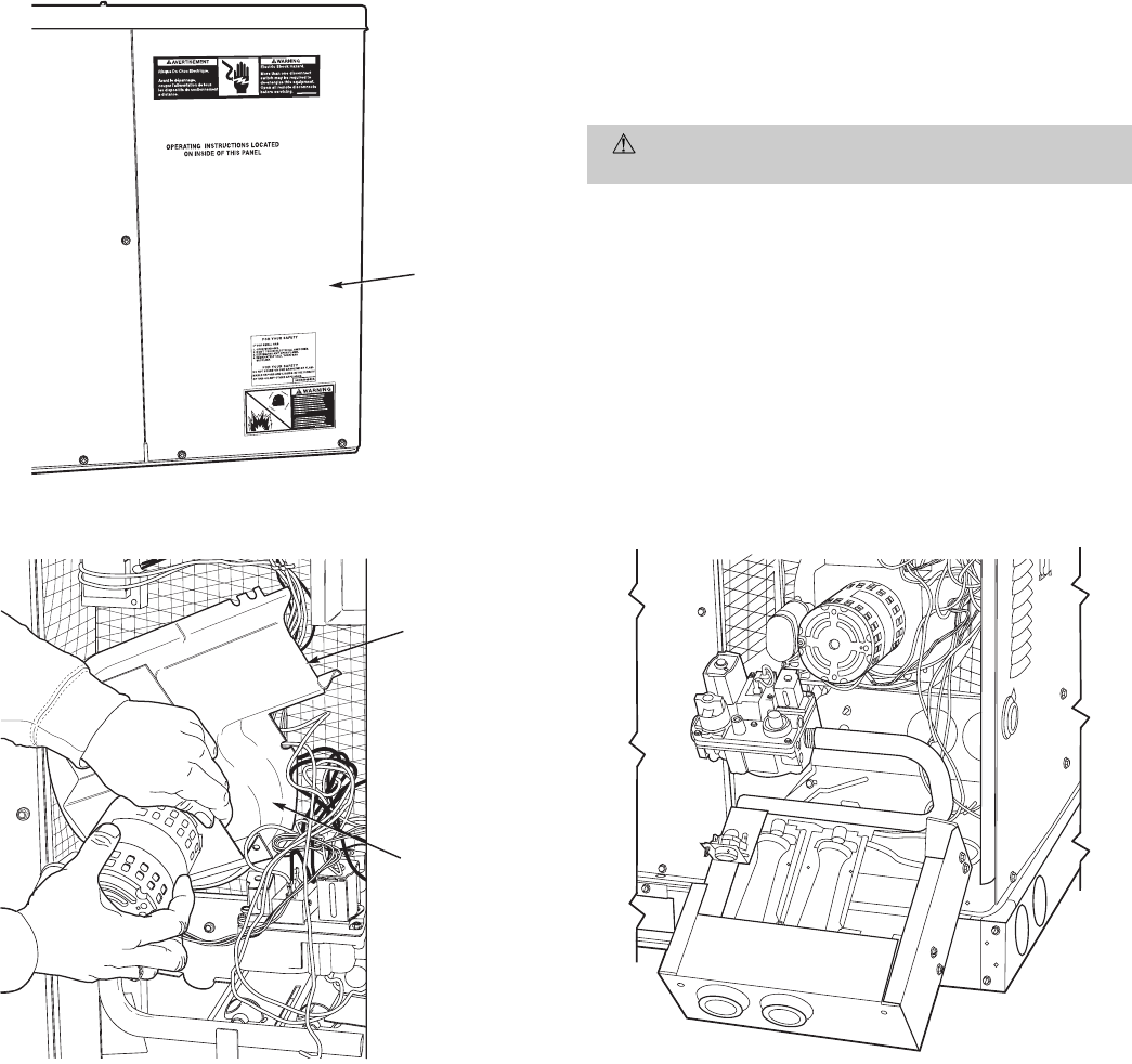
V. COMBUSTION-AIR BLOWER
Clean periodically to assure proper airflow and heating effi-
ciency. Inspect blower wheel every fall and periodically dur-
ing heating season. For the first heating season, inspect blower
wheel bimonthly to determine proper cleaning frequency.
To inspect blower wheel, remove draft hood assembly. Shine
a flashlight into opening to inspect wheel. If cleaning is re-
quired, remove motor and wheel as follows:
1. Remove burner access panel. (See Fig. 35.)
2. Remove the 7 screws that attach induced-draft motor
mounting plate to blower housing. (See Fig. 34.)
3. Slide the motor and blower wheel assembly out of the
blower housing. (See Fig. 36.) Clean the blower wheel.
If additional cleaning is required, continue with Steps 4
and 5.
4. To remove blower, remove 2 setscrews. (See Fig. 36.)
5. To remove motor, remove 4 screws that hold blower hous-
ing to mounting plate. Remove the motor cooling fan by
removing one setscrew. Remove nuts that hold motor to
mounting plate.
6. To reinstall, reverse the procedure outlined above.
VI. LIMIT SWITCH
Remove blower panel. Limit switch is located on the gas
partition.
VII. BURNER IGNITION
Unit is equipped with a direct spark ignition 100% lockout
system. Ignition module is located in the control box. Module
contains a self-diagnostic LED. During servicing, refer to la-
bel diagram for LED interpretation.
If lockout occurs, unit may be reset by either momentarily
interrupting power supply to unit, or turning selector switch
to OFF position at the thermostat.
VIII. MAIN BURNERS
At the beginning of each heating season, inspect for deterio-
ration or blockage due to corrosion or other causes. Observe
the main burner flames and adjust if necessary.
CAUTION: When servicing gas train, do not hit or
plug orifice spuds.
A. Removal of Gas Train
1. Shut off manual gas valve.
2. Shut off power to unit.
3. Remove burner access panel. (See Fig. 35.)
4. Disconnect gas piping at unit gas valve.
5. Remove wires connected to gas valve. Mark each wire.
6. Remove ignitor and sensor wires at the ignitor module.
7. Remove the mounting screw that attaches the burner
rack to the basepan. (See Fig. 34.)
8. Slide the burner rack out of the unit. (See Fig. 34
and 37.)
9. To reinstall, reverse the procedure outlined above.
BURNER
ACCESS
PANEL
Fig. 35 — Burner Access Panel
BLOWER
HOUSING
2 SETSCREWS
(HIDDEN)
Fig. 36 — Removal of Motor and Blower Wheel Fig. 37 — Burner Rack Removed
—46—

IX. CONDENSER COIL, EVAPORATOR COIL, AND
CONDENSATE DRAIN PAN
Inspect the condenser coil, evaporator coil, and condensate
drain pan at least once each year. Proper inspection and clean-
ing requires the removal of the unit top. See Unit Top Re-
moval section on page 45.
The coils are easily cleaned when dry; therefore, inspect and
clean the coils either before or after each cooling season. Re-
move all obstructions, including weeds and shrubs, that in-
terfere with the airflow through the condenser coil. Straighten
bent fins with a fin comb. If coated with dirt or lint, clean the
coils with a vacuum cleaner, using the soft brush attach-
ment. Be careful not to bend the fins. If coated with oil or
grease, clean the coils with a mild detergent-and-water solu-
tion. Rinse coils with clear water, using a garden hose. Be
careful not to splash water on motors, insulation, wiring, or
air filter(s). For best results, spray condenser coil fins from
inside to outside the unit. On units with an outer and inner
condenser coil, be sure to clean between the coils. Be sure to
flush all dirt and debris from the unit base.
Inspect the drain pan and condensate drain line when in-
specting the coils. Clean the drain pan and condensate drain
by removing all foreign matter from the pan. Flush the pan
and drain tube with clear water. Do not splash water on the
insulation, motor, wiring, or air filter(s). If the drain tube is
restricted, clear it with a ‘‘plumbers snake’’ or similar probe
device. Ensure that the auxiliary drain port above the drain
tube is also clear.
X. CONDENSER FAN
CAUTION: Keep the condenser fan free from all ob-
structions to ensure proper cooling operation. Never place
articles on top of the unit. Damage to unit may result.
1. Remove 2 screws at bottom and 2 screws along sides of
condenser air intake grille and remove plastic grille.
2. Inspect the fan blades for cracks or bends.
3. If fan needs to be removed, loosen the setscrew and slide
the fan off the motor shaft.
4. When replacing fan blade, position blade so that lead-
ing edge is
1
⁄
2
in. in front of fan orifice. See Fig. 23.
5. Ensure that setscrew engages the flat area on the mo-
tor shaft when tightening.
6. Replace grille.
XI. ELECTRICAL CONTROLS AND WIRING
Inspect and check the electrical controls and wiring annu-
ally. Be sure to turn off the gas supply, and then the electrical
power to the unit.
Remove the control, blower, and compressor compartment ac-
cess panels to locate all the electrical controls and wiring. Check
all electrical connections for tightness. Tighten all screw con-
nections. If any smoky or burned connections are noticed, dis-
assemble the connection, clean all the parts, restrip the wire
end and reassemble the connection properly and securely.
After inspecting the electrical controls and wiring, replace all
the panels. Start the unit, and observe at least one complete
heating cycle and one complete cooling cycle to ensure proper
operation. If discrepancies are observed in either or both op-
erating cycles, or if a suspected malfunction has occurred, check
each electrical component with the proper electrical instru-
mentation. Refer to the unit wiring label when making these
checkouts.
NOTE: Refer to the heating and/or cooling sequence of op-
eration in this publication as an aid in determining proper
control operation.
XII. REFRIGERANT CIRCUIT
Inspect all refrigerant tubing connections and the unit base
for oil accumulations annually. Detecting oil generally indi-
cates a refrigerant leak.
If oil is detected or if low cooling performance is suspected,
leak-test all refrigerant tubing using an electronic leak-
detector, halide torch, or liquid-soap solution. If a refrigerant
leak is detected, refer to Check for Refrigerant Leaks section
on page 23.
If no refrigerant leaks are found and low cooling perfor-
mance is suspected, refer to Checking and Adjusting Refrig-
erant Charge section on page 35.
XIII. GAS INPUT
The gas input does not require checking unless improper heat-
ing performance is suspected. If a problem exists, refer to
Start-Up section on page 23.
XIV. EVAPORATOR AIRFLOW
The heating and/or cooling airflow does not require checking
unless improper performance is suspected. If a problem ex-
ists, be sure that all supply- and return-air grilles are open
and free from obstructions, and that the air filter is clean. When
necessary, refer to Indoor Airflow and Airflow Adjustments
section on page 35 to check the system airflow.
XV. METERING DEVICE — ACUTROL™ DEVICE
This metering device is a fixed orifice and is located in the
header to the evaporator coil.
XVI. LIQUID LINE STRAINER
The liquid line strainer (to protect metering device) is made
of wire mesh and located in the liquid line on the inlet side of
the metering device.
—47—
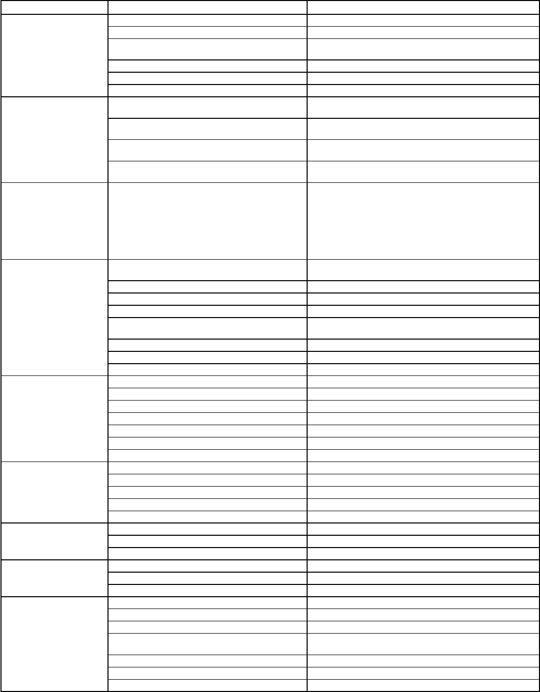
TROUBLESHOOTING
Cooling
SYMPTOM CAUSE REMEDY
Compressor and
condenser fan will
not start.
Power failure Call power company.
Fuse blown or circuit breaker tripped Replace fuse or reset circuit breaker.
Defective thermostat, contactor, transformer,
or control relay Replace component.
Insufficient line voltage Determine cause and correct.
Incorrect or faulty wiring Check wiring diagram and rewire correctly.
Thermostat setting too high Lower thermostat setting below room temperature.
Compressor will not
start but condenser
fan runs.
Faulty wiring or loose connections in
compressor circuit Check wiring and repair or replace.
Compressor motor burned out, seized, or
internal overload open Determine cause. Replace compressor.
Defective run/start capacitor, overload,
start relay Determine cause and replace.
One leg of 3-phase power dead Replace fuse or reset circuit breaker.
Determine cause.
Three-phase scroll
compressor (Units
588A048,060 and
589A036-060 only)
makes excessive
noise, and there
may be a low pres-
sure differential.
Scroll compressor is rotating in the
wrong direction Correct the direction of rotation by reversing the
3-phase power leads to the unit. Shut down unit to
allow pressures to equalize.
Compressor cycles
(other than normally
satisfying
thermostat).
Refrigerant overcharge or undercharge Recover refrigerant, evacuate system, and
recharge to capacities shown on nameplate.
Defective compressor Replace and determine cause.
Insufficient line voltage Determine cause and correct.
Blocked condenser Determine cause and correct.
Defective run/start capacitor, overload
or start relay Determine cause and replace.
Defective thermostat Replace thermostat.
Faulty condenser-fan motor or capacitor Replace.
Restriction in refrigerant system Locate restriction and remove.
Compressor
operates
continuously.
Dirty air filter Replace filter.
Unit undersized for load Decrease load or increase unit size.
Thermostat set too low Reset thermostat.
Low refrigerant charge Locate leak, repair, and recharge.
Leaking valves in compressor Replace compressor.
Air in system Recover refrigerant, evacuate system, and recharge.
Condenser coil dirty or restricted Clean coil or remove restriction.
Excessive head
pressure. Dirty air filter Replace filter.
Dirty condenser coil Clean coil.
Refrigerant overcharged Recover excess refrigerant.
Air in system Recover refrigerant, evacuate system, and recharge.
Condenser air restricted or air short-cycling Determine cause and correct.
Head pressure too
low. Low refrigerant charge Check for leaks, repair and recharge.
Compressor valves leaking Replace compressor.
Restriction in liquid tube Remove restriction.
Excessive suction
pressure. High heat load Check for source and eliminate.
Compressor valves leaking Replace compressor.
Refrigerant overcharged Recover excess refrigerant.
Suction pressure
too low. Dirty air filter Replace filter.
Low refrigerant charge Check for leaks, repair and recharge.
Metering device or low side restricted Remove source of restriction.
Insufficient evaporator airflow Increase air quantity. Check filter — replace if
necessary.
Temperature too low in conditioned area Reset thermostat.
Outdoor ambient below 40 F Install low-ambient kit.
Field-installed filter-drier restricted Replace.
—48—
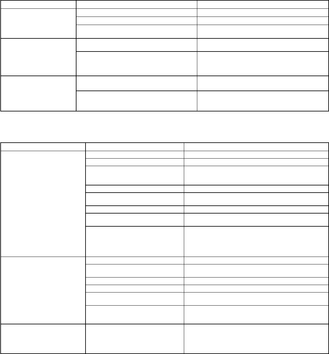
Cooling (cont)
SYMPTOM CAUSE REMEDY
Integrated control
motor
(units 589A048,060
208/230 v)
IFM does not run.
Blower wheel not secured to shaft Properly tighten blower wheel to shaft.
Insufficient voltage at motor Determine cause and correct.
Power connectors not properly
seated Connectors should snap easily; do not
force.
Integrated control
motor (units
589A048,060
208/230 v)
IFM runs when it
should be off.
Motor programmed with a delay
profile Allow a few minutes for motor to shut off.
With thermostat in OFF the voltage
on G,Y1,Y/Y2,W with respect to
common, should be
1
⁄
2
of actual
low voltage supply
If measured voltage is more than
1
⁄
2
, the
thermostat is incompatible with motor. If
voltage is less than
1
⁄
2
, the motor has failed.
Integrated control
motor (units
589A048,060
208/230 v) IFM
operation is
intermittent.
Water dripping into motor Verify proper drip loops in connector wires.
Connectors not firmly seated Gently pull wires individually to be sure they
are crimped into the housing.
IFM — Evaporator (Indoor) Fan Motor
Heating
SYMPTOM CAUSE REMEDY
Burners will not ignite. Water in gas line Drain. Install drip leg.
No power to furnace Check power supply fuses, wiring, or circuit breaker.
No 24-v power supply to control
circuit Check transformer.
NOTE: Some transformers have internal overcurrent
protection that requires a cool-down period to reset.
Miswired or loose connections Check all wiring and wirenut connections.
Burned-out heat anticipator in
thermostat Replace thermostat.
Broken thermostat wire Run continuity check. Replace wire if necessary.
Misaligned spark electrodes Check flame ignition and sense electrode positioning.
Adjust as necessary.
No gas at main burners 1. Check gas line for air. Purge as necessary.
NOTE: After purging gas line of air, wait at least
5 minutes for any gas to dissipate before attempt-
ing to light unit.
2. Check gas valve.
Inadequate heating. Dirty air filter Clean or replace filter as necessary.
Gas input to furnace too low Check gas pressure at manifold. Match with that on
unit nameplate.
Unit undersized for application Replace with proper unit or add additional unit.
Restricted airflow Clean or replace filter. Remove any restriction.
Blower speed too low Use faster speed tap if available, or install alternate
motor.
Limit switch cycles main burners Check rotation of blower, thermostat heat antic-
ipator settings, temperature rise of unit. Adjust as
necessary.
Poor flame characteristics. Incomplete combustion results in:
Aldehyde odors, carbon monox-
ide, sooting flame, floating flame
1. Tighten all screws around burner compartment.
2. Cracked heat exchanger. Replace.
3. Unit overfired. Reduce input (change orifices or
adjust gas line or manifold pressure).
4. Check burner alignment.
—49—
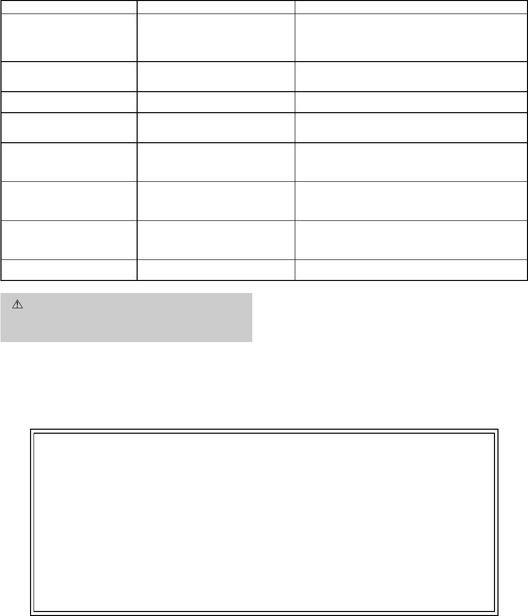
LED Troubleshooting — Error Code
SYMPTOM CAUSE REMEDY
Hardware failure.
(LED OFF) Loss of power to control module
(IGC). Check 5 amp fuse on IGC, power to unit, 24-v circuit
breaker, and transformer. Units without a 24-v circuit
breaker have an internal overload in the 24-v trans-
former. If the overload trips, allow 10 minutes for au-
tomatic reset.
Limit switch fault.
(LED 2 flashes) High temperature limit switch is
open. Check the operation of the indoor (evaporator) fan
motor. Ensure that the supply-air temperature rise is
in accordance with the range on the unit nameplate.
Flame sense fault.
(LED 3 flashes) The IGC sensed flame that
should not be present. Reset unit. If problem persists, replace control board.
4 consecutive limit switch
faults.
(LED 4 flashes)
Inadequate airflow to unit. Check operation of indoor (evaporator) fan motor and
that supply-air temperature rise agrees with range on
unit nameplate information.
Ignition lockout.
(LED 5 flashes) Unit unsuccessfully attempted
ignition for 15 minutes. Check ignitor and flame sensor electrode spacing,
gaps, etc. Ensure that flame sense and ignition wires
are properly terminated. Verify that unit is obtaining
proper amount of gas.
Induced-draft motor fault.
(LED 6 flashes) IGC does not sense that induced-
draft motor is operating. Check for proper voltage. If motor is operating, check
the speed sensor plug/IGC Terminal J2 connection.
Proper connection: PIN 1 — White, PIN 2 — Red,
PIN 3 — Black.
Rollout switch fault.
(LED 7 flashes) Rollout switch has opened. Rollout switch will automatically reset, but IGC will
continue to lockout unit. Check gas valve operation.
Ensure that induced-draft blower wheel is properly
secured to motor shaft. Reset unit at unit disconnect.
Internal control fault.
(LED 8 flashes) Microprocessor has sensed an
error in the software or hardware. If error code is not cleared by resetting unit power,
replace the IGC.
WARNING: If the IGC must be replaced, be sure to ground
yourself to dissipate any electrical charge that may be present
before handling new control board. The IGC is sensitive to static
electricity and may be damaged if the necessary precautions are
not taken.
IMPORTANT: Refer to Heating troubleshooting chart for additional
troubleshooting analysis.
LEGEND
IGC — Integrated Gas Unit Controller
LED — Light-Emitting Diode
SERVICE TRAINING
Packaged Service Training programs are an excellent way to increase your knowledge of the equip-
ment discussed in this manual, including:
• Unit Familiarization
• Installation Overview • Maintenance
• Operating Sequence
A large selection of product, theory, and skills programs are available, using popular video-based
formats and materials. All include video and/or slides, plus companion book.
Classroom Service Training which includes ‘‘hands-on’’ experience with the products in our labs
that can mean increased confidence that really pays dividends in faster troubleshooting and fewer
callbacks. Course descriptions and schedules are in our catalog.
CALL FOR FREE CATALOG 1-800-962-9212
[ ] Packaged Service Training [ ] Classroom Service Training
Copyright 1998 Bryant Heating & Cooling Systems CATALOG NO. CATALOG NO. 5358-802
START-UP CHECKLIST
(Remove and Store in Job File)
I. PRELIMINARY INFORMATION
MODEL NO.:
DATE:
SERIAL NO.:
TECHNICIAN:
II. PRE-START-UP (insert checkmark in box as each item is completed)
MVERIFY THAT ALL PACKING MATERIALS HAVE BEEN REMOVED FROM UNIT
MVERIFY THAT CONDENSATE CONNECTION IS INSTALLED PER INSTALLATION INSTRUCTIONS
MCHECK ALL ELECTRICAL CONNECTIONS AND TERMINALS FOR TIGHTNESS
MCHECK GAS PIPING FOR LEAKS
MCHECK THAT INDOOR (EVAPORATOR) AIR FILTER IS CLEAN AND IN PLACE
MVERIFY THAT UNIT INSTALLATION IS LEVEL
MCHECK FAN WHEEL AND PROPELLER FOR LOCATION IN HOUSING/ORIFICE AND SETSCREW
TIGHTNESS
III. START-UP
ELECTRICAL
SUPPLY VOLTAGE L1-L2 L2-L3 L3-L1
COMPRESSOR AMPS L1 L2 L3
COMPRESSOR AMPS L1 L2 L3
INDOOR (EVAPORATOR) FAN AMPS
TEMPERATURES
OUTDOOR (CONDENSER) AIR TEMPERATURE DB
RETURN-AIR TEMPERATURE DB WB
COOLING SUPPLY AIR
GAS HEAT SUPPLY AIR
PRESSURES
GAS INLET PRESSURE IN. WG
GAS MANIFOLD PRESSURE IN. WG
REFRIGERANT SUCTION PSIG
REFRIGERANT DISCHARGE PSIG
MVERIFY REFRIGERANT CHARGE USING CHARGING TABLES
MVERIFY THAT 3-PHASE SCROLL COMPRESSOR (588A048,060 AND 589A036-060 UNITS) ROTATING IN
CORRECT DIRECTION
----------------------------------------------------------------------------------------
CUT ALONG DOTTED LINE CUT ALONG DOTTED LINE
Copyright 1998 Bryant Heating & Cooling Systems CATALOG NO. CATALOG NO. 5358-802
CL-1
