Bryant Tstatbbnq001 Users Manual
TSTATBBNQ001 to the manual f298d578-ecd8-403b-bd55-ae562784ede1
2015-02-02
: Bryant Bryant-Tstatbbnq001-Users-Manual-412173 bryant-tstatbbnq001-users-manual-412173 bryant pdf
Open the PDF directly: View PDF ![]() .
.
Page Count: 24
72
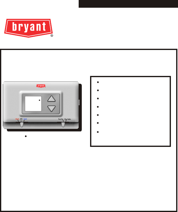
Battery Operated
4-Wire Operation
Millivolt Compatible
Digital Display
DC Voltage Compatible
Stage: 1-Heat, 1-Cool
Easy Slide Switch
Operation
USERS INFORMATION MANUAL
MODEL TSTATBBNQ001
NON-PROGRAMMABLE DIGITAL
THERMOSTAT
NOTE TO INSTALLER:
This manual must be left with the equipment user.
Heating & Cooling Systems
Heat Cool Thermostat
SINGLE STAGE HEAT & COOL
THERMOSTAT

Page 1
Table Of Contents
LOCATION OF CONTROLS
DISPLAY
NORMAL OPERATION
PREPARATION
REMOVE OLD THERMOSTAT
WIRE CONNECTIONS
JUMPER CONFIGURATION
TEST OPERATION
TROUBLESHOOTING
WARRANTY
2
4
5
6
7
10
17
20
21
INSTALLATION AND BATTERY
REPLACEMENT
8
24
Bryant Heating & Cooling Systems Patents Pending 4/03
TSTATBBNQ001
Safety Warnings
Page 2
CAUTION Follow Installation Instructions carefully.
DISCONNECT POWER TO THE HEATER -
AIR CONDITIONER BEFORE REMOVING
THE OLD THERMOSTAT AND INSTALLING
THE NEW THERMOSTAT.
WARNING
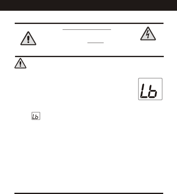
The 2 Alkaline “AA” batteries must be replaced at least
every 12 months to assure proper operation.
The thermostat will display the Low Battery
code (fig. 1) on the display of the thermostat
when it is time to replace the batteries.
When is displayed the batteries must be replaced
immediately. The manufacturer cannot be liable for
improper operation of the thermostat if the batteries are
not immediately replaced.
The annual battery replacement is especially critical in
locations subject to freezing temperatures. The
thermostat will be unable to turn on the Heat if the
batteries are exhausted.
CAUTION
This device complies with Part 15 of the FCC rules.
Operation is subject to the following 2 conditions:
(1) This device may not cause harmful interference, and (2)
This device must accept any interference received, including
interference that may cause undesired operation.
FIG. 1
Location of Controls
Page 3
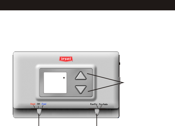
MODE SWITCH
Heat, Cool or Off On or Auto
FAN SWITCH
UP & DOWN
BUTTONS
72
Display
Page 4
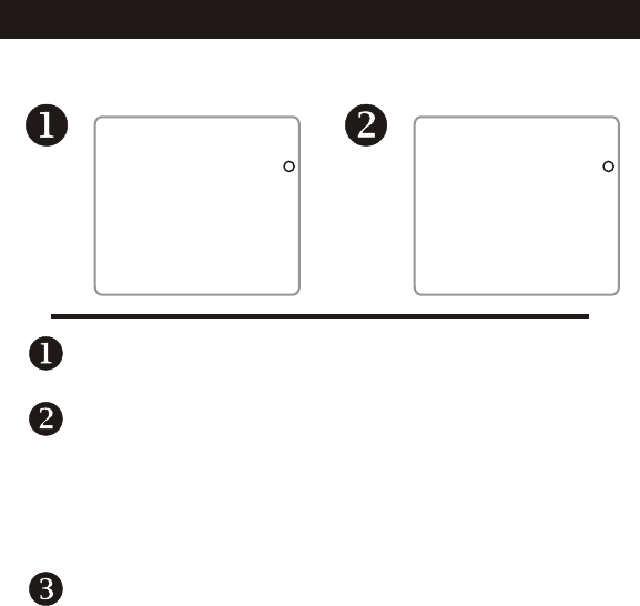
Current room temperature.
If the Up or Down arrow buttons are pressed the
thermostat will show the desired Set Temp temperature
indicator. Once this screen is reached you may use the
Up or Down arrow buttons to adjust the desired room
temperature.
After five seconds with no button presses the
thermostat will revert back to show the current
room temperature.
78 74
SET TEMP

Page 5
Normal Operation
Manual Operation
Select heat or cool with the mode switch.
Normally leave the fan switched to auto.
In fan auto, the fan will turn on only with a heat
or cool demand. When Fan On is selected, the
fan will run continuously, even when the mode
switch is set to Off.
Adjust the desired set temperature with the
Up or Down buttons.
MODE SWITCH
Heat, Cool or Off On or Auto
FAN SWITCH
UP & DOWN
BUTTONS
72
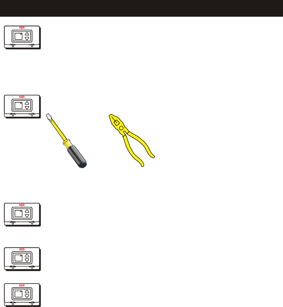
Step #1 Preparation
Page 6
These tools will be required:
Flat Blade
Screwdriver
Wire cutter
& Stripper
Make sure your Heater/Air Conditioner
is working properly before beginning
installation of the thermostat.
Carefully unpack the thermostat.
Save the screws and instructions.
Turn off the power to the Heating/Air
Conditioning system at the main fuse
panel. Most residential systems have
a separate breaker for disconnecting
power to the furnace.
Proper installation of the thermostat will be
accomplished by following these step
by step instructions. If you are unsure
about any of these steps, call a qualified
technician for assistance.
72
Heat Off Cool Fan On
FanA uto
72
Heat Off Cool Fan On
FanA uto
72
Heat Off Cool Fan On
FanA uto
72
Heat Off Cool Fan On
FanA uto
72
Heat Off Cool Fan On
FanA uto
Page 7
Step #2 Remove & Replace Old Thermostat
Remove the cover of the old thermostat.
If it does not come off easily check for
screws.
Loosen the screws holding the thermostat
base or subbase to the wall, and lift away.
Disconnect the wires from the old
thermostat. Tape the ends of the wires
as you disconnect them, and mark them
with the letter of the terminal for easy
reconnection to the new thermostat.
Keep the old thermostat for reference
purposes, until your new thermostat is
functioning properly.
72
Heat Off Cool Fan On
FanA uto
72
Heat Off Cool Fan On
FanA uto
72
Heat Off Cool Fan On
FanA uto
72
Heat Off Cool Fan On
FanA uto

Page 8
The top of the thermostat housing has two (2) screw-
driver slots to assist when seperating.
Repeat the procedure in the other screw driver slot.
Separate the housing halves by pulling the top
forward until the pins release, and then lift the bottom
out.
SCREWDRIVER
SLOTS
The batteries must be replaced
immediately when the thermostat
displays the Low Battery code (fig.1). FIG. 1
To Open The Thermostat
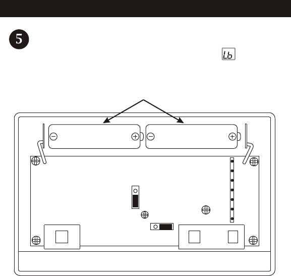
Step #3 Installation and Battery Replacement
To pull the housing apart, insert a small blade screw-
driver into the slot and rotate 90 . This will release
the top housing snaps.
Page 9
Battery Replacement
REPLACE WITH ALKALINE BATTERIES AT LEAST ONCE
EVERY YEAR, OR WHEN THE “LOW BATTERY” ICON
APPEARS (pages 2,8).
USE “AA” SIZE
ALKALINE BATTERIES USE “AA” SIZE
ALKALINE BATTERIES
POSITION BATTERIES AS SHOWN
FAN W/ HEAT
HEAT PUMP
1
2
3
1 2 3
J1
J2
72
Heat Off Cool Fan On
FanA uto
If the terminal designations on your old
thermostat do not match those on the
new thermostat, refer to the chart below,
or the wiring diagrams that follow.
Wire from the
old thermostat
terminal marked Function
Install on the
new thermostat
connector marked
Y1 or Y Cooling Y
PowerRh, R, M, Vr, A R
B
BRev. Valve
(Energize to Heat)
W1, W or H Heating W
G or F Fan G
O
Rev. Valve
(Energize to Cool)
O
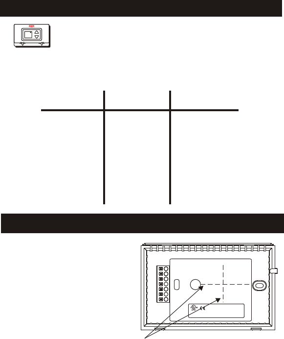
A label is provided on the backplate
that prevents drafts, originating inside
the wall, from entering the thermostat.
These drafts, left unchecked, may
cause incorrect room temperature
readings.
Please do not remove this label
from the thermostat. Insert the wires
through the slots provided in the label
as shown in Fig. 1
Thermal Insulating Sheet
4Z95
MODEL: TSTATBBNQ001
97061606
MADE IN CHINA
USE SIZE “AA”
ALKALINE BATTERIES
W
Y
B
O
G
R
Fig. 1
Wire Slots
Step #4 Wire Connections
Page 10
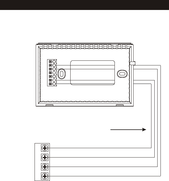
Sample Wiring Diagrams
FAN
COOLING
POWER
WGRY
W
Y
B
O
G
R
4 Wire, 1 Stage Cooling, 1 Stage Gas Heat Residential Gas or Electric Heat *,
Electric Cool, split systems & package
units
Page 11
GAS OR
ELECTRIC HEAT
4 Conductor 18 to 22 gauge
unshielded cable from the
thermostat to the equipment.

Page 12
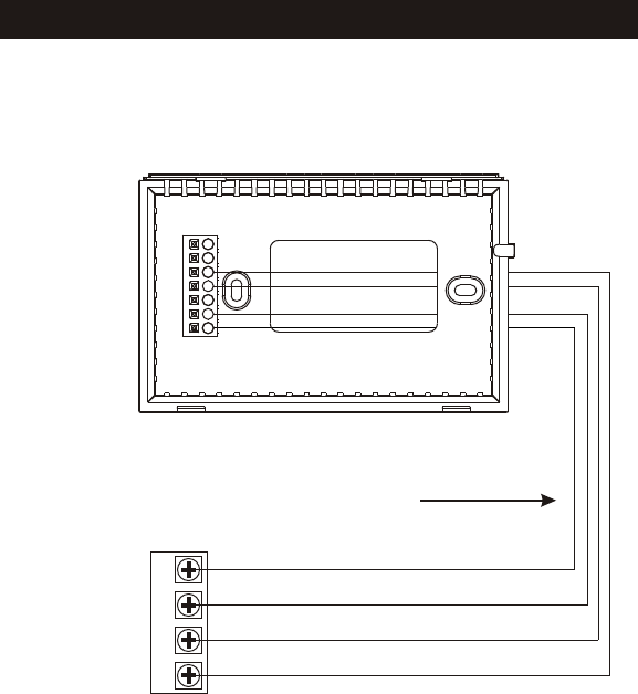
Sample Wiring Diagrams
4 Wire, 1 Stage Cooling, 1 Stage Heat-Heat Pump with O reversing valve*.
Residential Heat Pumps, split systems & package units, with no auxiliary heat.
FAN
POWER
GR
COMPRESSOR
Y
W
Y
B
O
G
R
REVERSING VALVE
O
*For Heat Pump or Electric Heat applications see page 17 or 18 for Jumper configuration.
4 Conductor 18 to 22 gauge
unshielded cable from the
thermostat to the equipment.
Page 13
Sample Wiring Diagrams
4 Wire, 1 Stage Cooling, 1 Stage Heat-Heat Pump with B reversing valve*.
Residential Heat Pumps, split systems & package units, with no auxiliary heat.
FAN
POWER
GR
COMPRESSOR
Y
W
Y
B
O
G
R
REVERSING VALVE
B
*For Heat Pump or Electric Heat applications see page 17 or 18 for Jumper configuration.
4 Conductor 18 to 22 gauge
unshielded cable from the
thermostat to the equipment.
Page 14
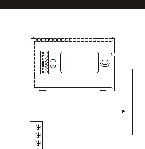
Sample Wiring Diagrams
FAN
POWER
GR
W
W
Y
B
O
G
R
3 Wire, 1 Stage Heat Residential Gas or Electric Heat units
with a separately controlled fan.
GAS OR
ELECTRIC HEAT
3 Conductor 18 to 22 gauge
unshielded cable from the
thermostat to the equipment.
Page 15
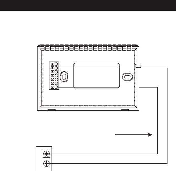
Sample Wiring Diagrams
POWER
WR
W
Y
B
O
G
R
2 Wire, 1 Stage Gas Heat Residential Gas or Millivolt units.
GAS OR
ELECTRIC HEAT
2 Conductor 18 to 22 gauge
unshielded cable from the
thermostat to the equipment.

Page 16
Sample Wiring Diagrams
FAN
COOLING
POWER
GRY
W
Y
B
O
G
R
3 Wire, 1 Stage Cooling Residential Electric Cool units
3 Conductor 18 to 22 gauge
unshielded cable from the
thermostat to the equipment.
Page 17
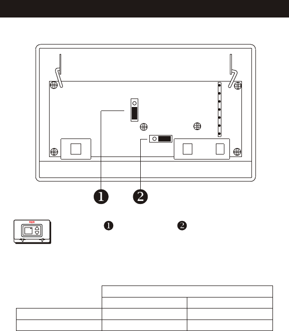
Step #5 Jumper Configuration
FAN W/ HEAT
HEAT PUMP
1
2
3
1 2 3
J1
J2
Jumper and Jumper are shown in the
factory default positions for typical gas
furnace heating with electric cooling.
*Outputs active - For normal operation do not connect to equipment
OUTPUTS
No Demand With Demand
Cooling Mode
Heating Mode
O* Y, G, O*
B* W
Figure-A)
72
Heat Off Cool Fan On
FanA uto
Page 18
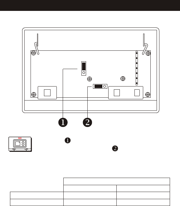
Step #5 Jumper Configuration
FAN W/ HEAT
HEAT PUMP
1
2
3
1 2 3
J1
J2
Jumper is used to select Fan On (G)
with Heat (W). Jumper shown in the
factory default position.
*Outputs active - For normal operation do not connect to equipment
OUTPUTS
No Demand With Demand
Cooling Mode
Heating Mode
O* Y, G, O*
B* W, G
Figure-B)
72
Heat Off Cool Fan On
FanA uto

Page 19
Step #5 Jumper Configuration
FAN W/ HEAT
HEAT PUMP
1
2
3
1 2 3
J1
J2
Jumper and Jumper are used to select
heat pump operation. Note: Thermostat
Does Not Have Auxiliary Heat / Emergency
Heat Capability. Leave jumpers in original
factory default positions (figure-A) for non
heat pump applications.
Figure-C)
OUTPUTS
No Demand With Demand
Cooling Mode
Heating Mode
O* Y, G, O*
B** Y , G, B**
* Output active in Cooling
** Output active in Heating
Y active in Heating
72
Heat Off Cool Fan On
FanA uto

Page 20
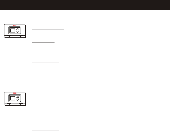
Step #5 Test Operation
Adjust the Slide Switch until it is located
under the word HEAT on the thermostat.
Press the Up or Down buttons until the set
temperature is 10 degrees above room
temperature. The HVAC unit should
energize in the heating mode (pages 4-5).
Adjust the Slide Switch until it is located
under the word COOL on the thermostat.
Press the Up or Down buttons until the set
temperature is 10 degrees below room
temperature. The HVAC unit should
energize in the cooling mode (pages 4-5).
Turn on the power to the Heating/Air
Conditioning system.
Adjust the Slide Switch until it is located
under the word OFF. Adjust the other slide
switch until it is located under the word Fan
On. The fan should turn on and run
continuously (pages 4-5).
72
Heat Off Cool Fan On
FanA uto
72
Heat Off Cool Fan On
FanA uto
72
Heat Off Cool Fan On
FanA uto
72
Heat Off Cool Fan On
FanA uto
Page 21
Troubleshooting
SYMPTOM: The slide switches on the thermostat
are very difficult to move.
CAUSE: The backplate of the thermostat is
deformed by being screwed tightly into a
wall that is not perfectly flat.
REMEDY: Loosen the screws holding the
thermostat into the wall.
72
Heat Off Cool Fan On
FanA uto
72
Heat Off Cool Fan On
FanA uto
SYMPTOM: The air conditioning does not
attempt to turn on.
CAUSE: The cooling setpoint is set too
high or the Mode Switch is not set for
Cool, or the batteries are too weak.
REMEDY: Consult the Normal Operation
section of this manual to lower the
cooling setpoint and to correct the
Mode Switch position, or replace
the batteries (page 9).
Page 22
Troubleshooting
4Z95
72
Heat Off Cool Fan On
FanA uto
C
c
F
FOR HOME OR OFFICE USE
Tested to Comply
with FCC Standards
Battery Stat TSTATBBNQ001
SYMPTOM: The heating does not attempt
to turn on.
CAUSE: The heating setpoint is set too
low or the Mode Switch is not set for
Heat, or the batteries are too weak.
REMEDY: Consult the Normal Operation
section in this manuals to raise the
heating setpoint and to correct the
Mode Switch position, or replace
the batteries (Page 9).

THIS WARRANTY DOES NOT INCLUDE LABOR OR OTHER COSTS incurred for diagnosing, repairing,
removing, installing, shipping, servicing or handling of either defective parts or replacement
parts. Such costs may be covered by a separate warranty provided by the installer.
THIS WARRANTY APPLIES ONLY TO PRODUCTS IN THEIR ORIGINAL
INSTALLATION LOCATION AND BECOMES VOID UPON REINSTALLATION.
LIMITATIONS OF WARRANTIES – ALL IMPLIED WARRANTIES (INCLUDING IMPLIED
WARRANTIES OF FITNESS FOR A PARTICULAR PURPOSE AND MERCHANTABILITY)
ARE HEREBY LIMITED IN DURATION TO THE PERIOD FOR WHICH THE LIMITED
WARRANTY IS GIVEN. SOME STATES DO NOT ALLOW LIMITATIONS ON HOW
LONG AN IMPLIED WARRANTY LASTS, SO THE ABOVE MAY NOT APPLY TO YOU.
THE EXPRESSED WARRANTIES MADE IN THIS WARRANTY ARE EXCLUSIVE AND
MANY NOT BE ALTERED, ENLARGED, OR CHANGED BY ANY DISTRIBUTOR,
DEALER, OR OTHER PERSON WHATSOEVER.
ALL WORK UNDER THE TERMS OF THIS WARRANTY SHALL BE PERFORMED
DURING NORMAL WORKING HOURS. ALL REPLACEMENT PARTS, WHETHER
NEW OR REMANUFACTURED, ASSUME AS THEIR WARRANTY PERIOD ONLY THE
REMAINING TIME PERIOD OF THIS WARRANTY.
THE MANUFACTURER WILL NOT BE RESPONSIBLE FOR:
1. Normal maintenance as outlined in the installation and servicing instructions or owners
manual including filter cleaning and/or replacement and lubrication.
2. Damage or repairs required as a consequence of faulty installation, misapplication,
abuse, improper servicing, unauthorized alteration or improper operation.
3. Failure to start due to voltage conditions, blown fuses, open circuit breakers or other
damages due to the inadequacy or interruption of electrical service.
4. Damage as a result of floods, winds, fires, lightning, accidents, corrosive environments or
other conditions beyond the control of the Manufacturer.
5. Parts not supplied or designated by the Manufacturer, or damages resulting from their
use.
6. Manufacturer products installed outside the continental U.S.A., Alaska, Hawaii, and
Canada.
7. Electricity or fuel costs or increases in electricity or fuel costs from any reason whatsoever
including additional or unusual use of supplemental electric heat.
8. ANY SPECIAL INDIRECT OR CONSEQUENTIAL PROPERTY OR COMMERCIAL
DAMAGE OF ANY NATURE WHATSOEVER. Some states do not allow the exclusion of
incidental or consequential damages, so the above may not apply to you.
This warranty gives you specific legal rights, and you may also have other rights which may
vary form state to state.
Page 23
Warranty
5-Year Warranty - This Product is warranted to be free from defects in material and
workmanship. If it appears within five years from the date of original installation, whether or
not actual use begins on that date, that the product does meet this warranty, a new or
remanufactured part, at the manufacturer’s sole option, to replace any defective part will
be provided without charge for the part itself; PROVIDED the defective part is returned to
the distributor through a qualified servicing dealer.
Form No. OM17-55
Catalog No. 13TS-TA63
P/N 88-400
Rev. 2
