BuildingLink HPBU01 RF transceiver module User Manual HPBU01 TR 915 20180425
BuildingLink RF transceiver module HPBU01 TR 915 20180425
Users manual
RF transceiver module
HPBU01-TR-915
Datasheet
BuildingLink
85 5
th
Ave 3
rd
New York NY 10003
HPBU01-TR-915 Datasheet
1. Introduction
The HPBU01-TR-915 is a compact, low power, bidirectional transceiver module in the
915 MHz range utilizing Sub-GHz technology. The module provides long range and high
output power while also reducing current consumption to a minimum. The HPBU01-TR-
915 also utilizes the widely used ATmega328P processor. The coupling of Sub-GHz
transceiver technology and ATmega328P processor allows for faster prototyping and
fast time to market. The HPBU01-TR-915 module utilizes a patch antenna to reduce the
need for RF development and antenna tuning and provide consistent range
expectations.
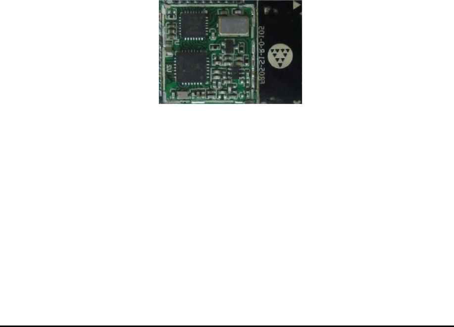
Figure 1-1: Picture of HPBU01-TR-915
Specifications
- Sub-GHz Transceiver
- 902 MHz – 928 MHz Frequency
Range
- Built in AES-128 encryption
- Down to -120 dBm at 1.2kbps
sensitivity
- Programmable output to +20 dBm
(100mW)
- UART, SPI, and I2C interface
- Customizable GPIO for analog /
digital signals
- ATmega328P Co-Processor
- Supply voltage range from 2.4v to
3.6v
Application
- Wireless Sensor Networks
- Home and Building Automation
- Wireless Alarm and Security
Systems
- Meter Reading
- Remote Control
- Telemetry
- Environmental Alerts
HPBU01-TR-915 Datasheet
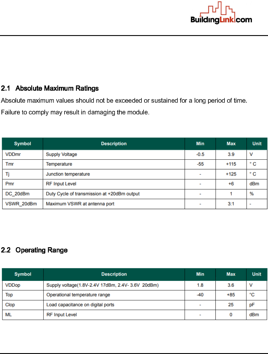
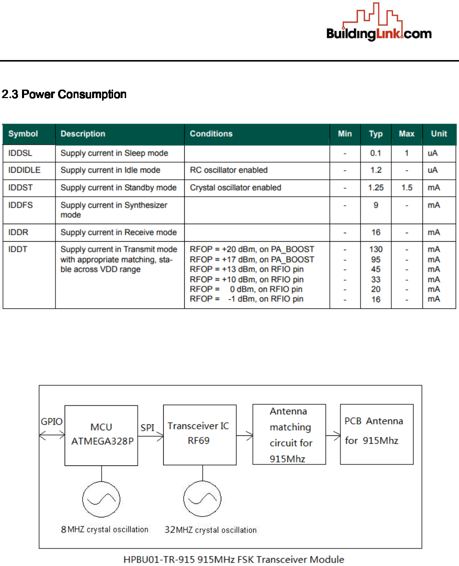
2. Electrical Characteristics
HPBU01-TR-915 Datasheet
HPBU01-TR-915 Datasheet
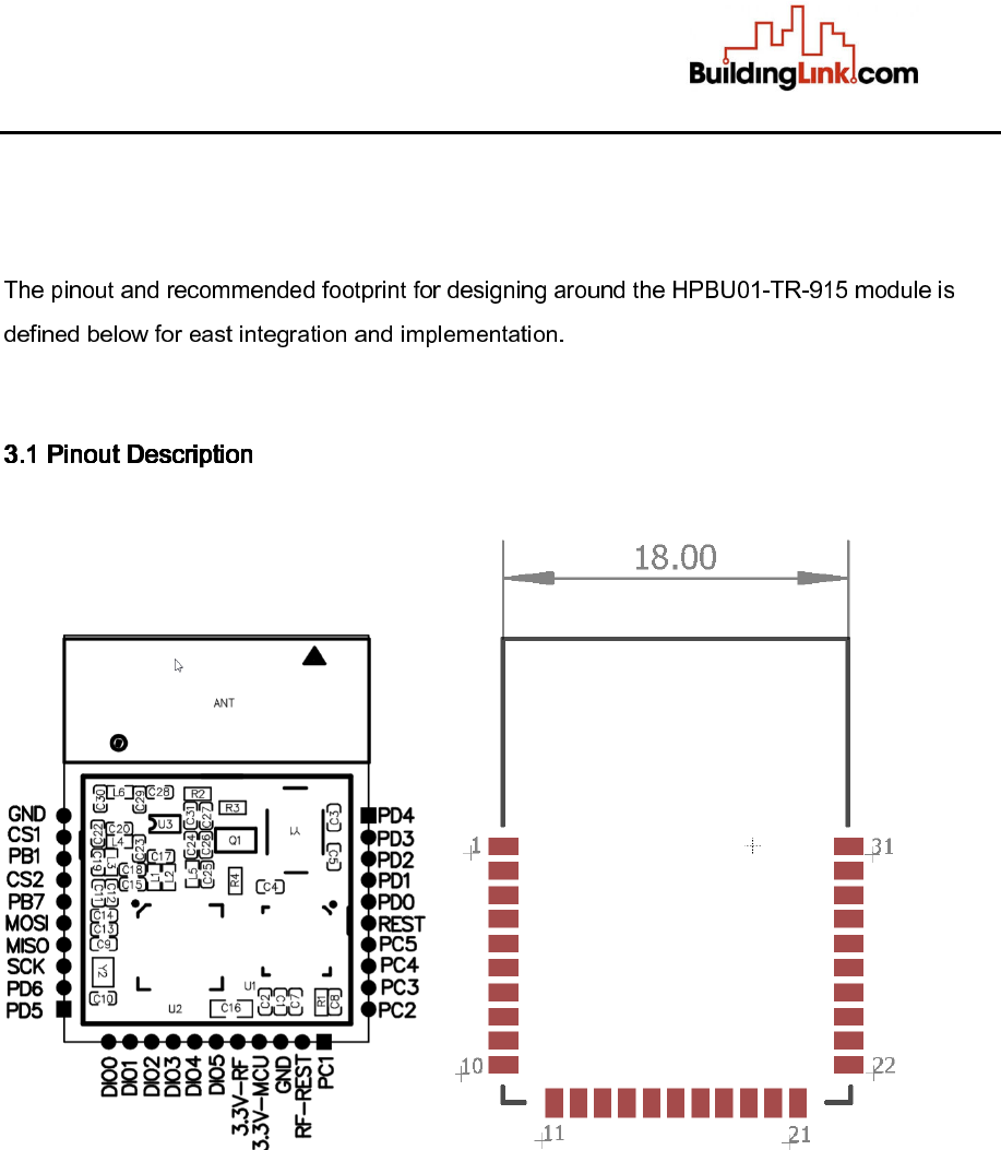
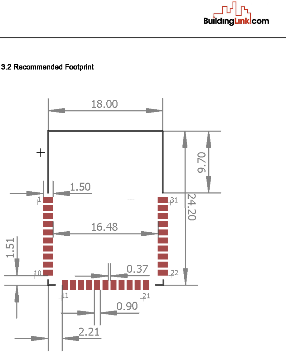
3. Module Package
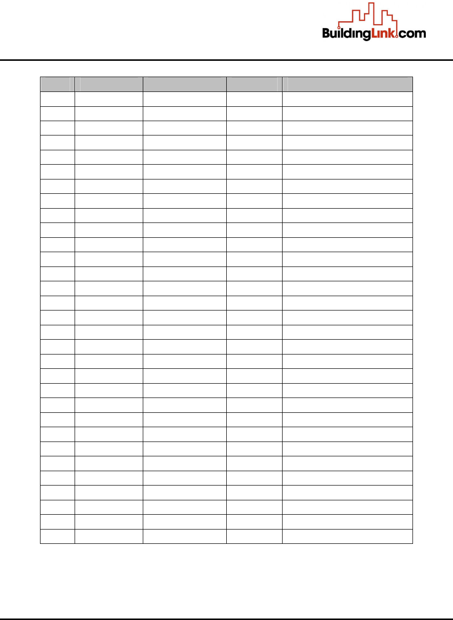
HPBU01-TR-915 Datasheet
PIN
PIN Name
Pin Type
MCU Pin
Description
1 GND Supply Ground Connection
2
CS1
D IN/OUT
PB2
DIGITAL IO / SPI NSS
3
PB1
D IN/OUT
PB1
DIGITAL IO
4 CS2 D IN/OUT PB0 DIGITAL IO
5
PD
7
D IN/OUT
PD7
DIGITAL IO
6 MOSI D IN/OUT PB3 DIGITAL IO / SPI MOSI
7
MISO
D IN/OUT
PB4
DIGITAL IO / SPI MISO
8
SCK
D
IN/OUT
PB5
DIGITAL IO / SPI SCK
9 PD6 D IN/OUT PD6 DIGITAL IO
10
PD5
D IN/OUT
PD5
DIGITAL IO
11
DIO0
D IN/OUT
DIO0
RF IO Pin
12 DIO1 D IN/OUT DIO1 RF IO Pin
13
DIO2
D IN/OUT
DIO2
RF IO Pin
14
DIO3
D IN/OUT
DIO3
RF IO Pin
15 DIO4 D IN/OUT DIO4 RF IO Pin
16 DIO5 D IN/OUT DIO5 RF IO Pin
17 3.3V-RF Supply Supply Voltage
18
3.3V
-
MCU
Supply
Supply Voltage
19
GND
Supply
Ground Connection
20 RF-REST D IN REST Reset Pin for RF69
21
PC1
D IN/OUT, A IN
PC1
DIGITAL IO / ADC
22
PC2
D IN/OUT, A IN
PC2
DIGITAL IO / ADC
23 PC3 D IN/OUT, A IN
PC3 DIGITAL IO / ADC
24
PC4
D IN/OUT, A IN
PC4
DIGITAL IO / ADC
25
PC5
D IN/OUT, A IN
PC5
DIGITAL IO / ADC
26
REST
D IN
PC6
Reset Pin for MCU
27
PD0
D IN/OUT
PD0
DIGITAL IO / RX
28 PD1 D IN/OUT PD1 DIGITAL IO / TX
29
PD2
D IN/OUT
PD2
DIGITAL IO / INT0
30
PD3
D IN/OUT
PD3
DIGITAL IO / INT1
31 PD4 D IN/OUT PD4 DIGITAL IO
HPBU01-TR-915 Datasheet
This device complies with part 15 of the FCC Rules. Operation is subject to the
following two conditions:
(1) This device may not cause harmful interference, and
(2) This device must accept any interference received, including interference that may
cause undesired operation.
Any changes or modifications not expressly approved by the party responsible for
compliance could void the user's authority to operate the equipment.
This equipment has been tested and found to comply with the limits for a Class B digital
device, pursuant to Part 15 of the FCC Rules. These limits are designed to provide
reasonable protection against harmful interference in a residential installation. This
equipment generate, uses and can radiate radio frequency energy and, if not installed
and used in accordance with the instructions, may cause harmful interference to radio
communications. However, there is no guarantee that interference will not occur in a
particular installation.
If this equipment does cause harmful interference to radio or television reception, which
can be determined by turning the equipment off and on, the user is encouraged to try to
correct the interference by one or more of the following measures:
-- Reorient or relocate the receiving antenna.
-- Increase the separation between the equipment and receiver.
-- Connect the equipment into an outlet on a circuit different from that to which the
receiver is connected.
-- Consult the dealer or an experienced radio/TV technician for help.
To maintain compliance with FCC’s RF Exposure guidelines, this equipment should be
installed and operated with minimum distance between 20cm the radiator your body:
Use only the supplied antenna.