Burnham Pf 3 Series Installation And Operation Manual
2015-06-08
: Burnham Burnham-Pf-3-Series-Installation-And-Operation-Manual-738091 burnham-pf-3-series-installation-and-operation-manual-738091 burnham pdf
Open the PDF directly: View PDF ![]() .
.
Page Count: 16
INSTALLATION
AND
OPERATING INSTRUCTIONS
FOR
PF-3
FORCED DRAFT
BOILER
-
BURNER UNITS
SECTION
I
-
GENERAL INFORMATION
-
Page
3
SECTION I1
-
INSTALLATION INSTRUCTIONS
-
Page
4
SECTION I11
-
OPERATING AND SERVICE INSTRUCTIONS
-
Page
13
NOTE
:
For optimum performance and serviceability from this unit adhere to the following recommendations:
\
1-Clean Flueways at least once a year-preferably at the end of heating season to remove soot and scale.
Inside of Firebox should also be cleaned at the same time.
2-Have Oil Burner and Controls checked at least once a year or as may be necessitated.
3-Retain your contractor or a competent serviceman to assure that the unit is properly adjusted and main-
,tained.
IMPORTANT: BEFORE STARTING TO INSTALL THIS OIL HEATING UNIT, READ THESE
INSTRUCTIONS CAREFULLY. KEEP INSTRUCTIONS NEAR OIL HEATING UNIT FOR
REFERENCE BY OWNER AND SERVICEMAN.
For service and repairs to the heating plant, call your Heating Contractor. When seeking information on the boiler,
provide series and size designation shown on rating plate.
Boiler Number Type Firing Type System
Heating Contractor
Address
-
.-
--Phone No
BURNHAM
CORPORATION
HYDRONICS DIVISION
Laneaster,
Pennsylvania
17604
Wrm
No.
62008E-1/81-1200f
'URN
4
$
X
18
OPENING,
/3"
SUPPLY
\
8"
DIA. VENT
---
REMOVABLE
PANEL
8"
/
8"
K.O.
DRAIN VALVE
FRONT VlEW
FLUSH JACKET SIDE VlEW EXTENDED JACKET
MODEL NO. OF
SECTIONS
1
A
1
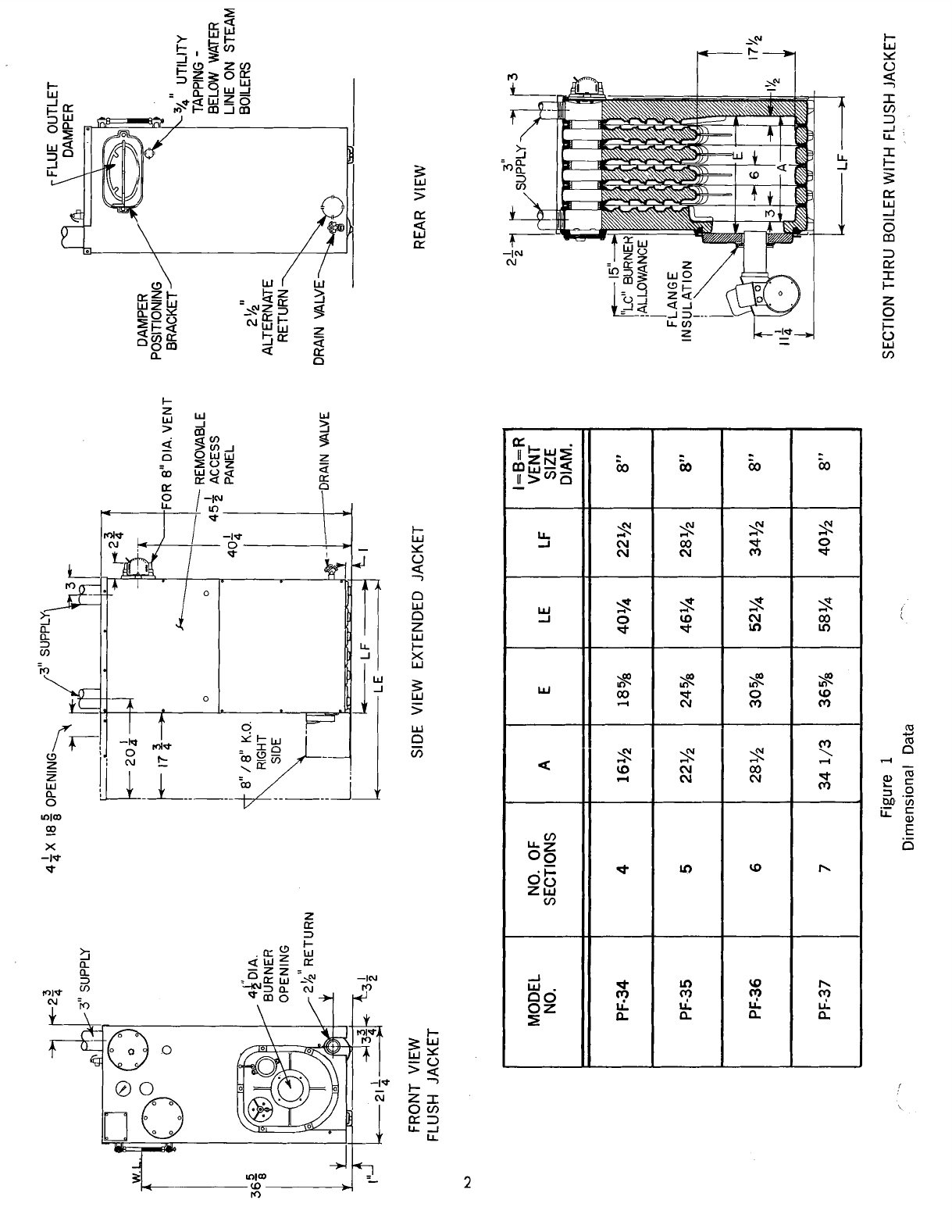
Figure
1
,-
-.
Dimensional Data
VENT
LE
/
LF
1
SIZE
1
DIAM.
r
FLUE OUTLET
DAMPER
&k
DAMPER
POSITIONIN
BRACKET
2
vzrl
ALTERNATE
RETURN
-
3411
UTILITY
TAPPING
-
BELOW WATER
LINE ON STEAM
BOILERS
DRAIN VALVE
%
-
1
REAR VIEh'
L-LF
---d
SECTION THRU BOILER WITH FLUSH JACKET
SECTION I
GENERAL
INFORMATION
INSPECT SHIPMENT carefully for any signs of dam-
@
PROVIDE CLEARANCE of at least
24"
on the
age. All equipment is carefully masufactured, inspected right side and back of the unit for cleaning of flues. Pro-
and packed by experienced workmen. Our responsibility vide a minimum of
20"
clearance in front for servicing of
ceases upon delivery of boiler to the carrier in good con- equipment,
30"
if boiler is equipped with jacket extension.
dition. Any claims for damage in shipment must be filed If boiler is equipped with tanldess heater, additional
immediately against the carrier by the consignee. No allowance may have to be made for installation and serv-
claims for variances from, or shortage in orders, will be icing of heater, see table below:
allowed by the manufacturer, unless presented within
sixty
(60)
days after receipt of goods.
a
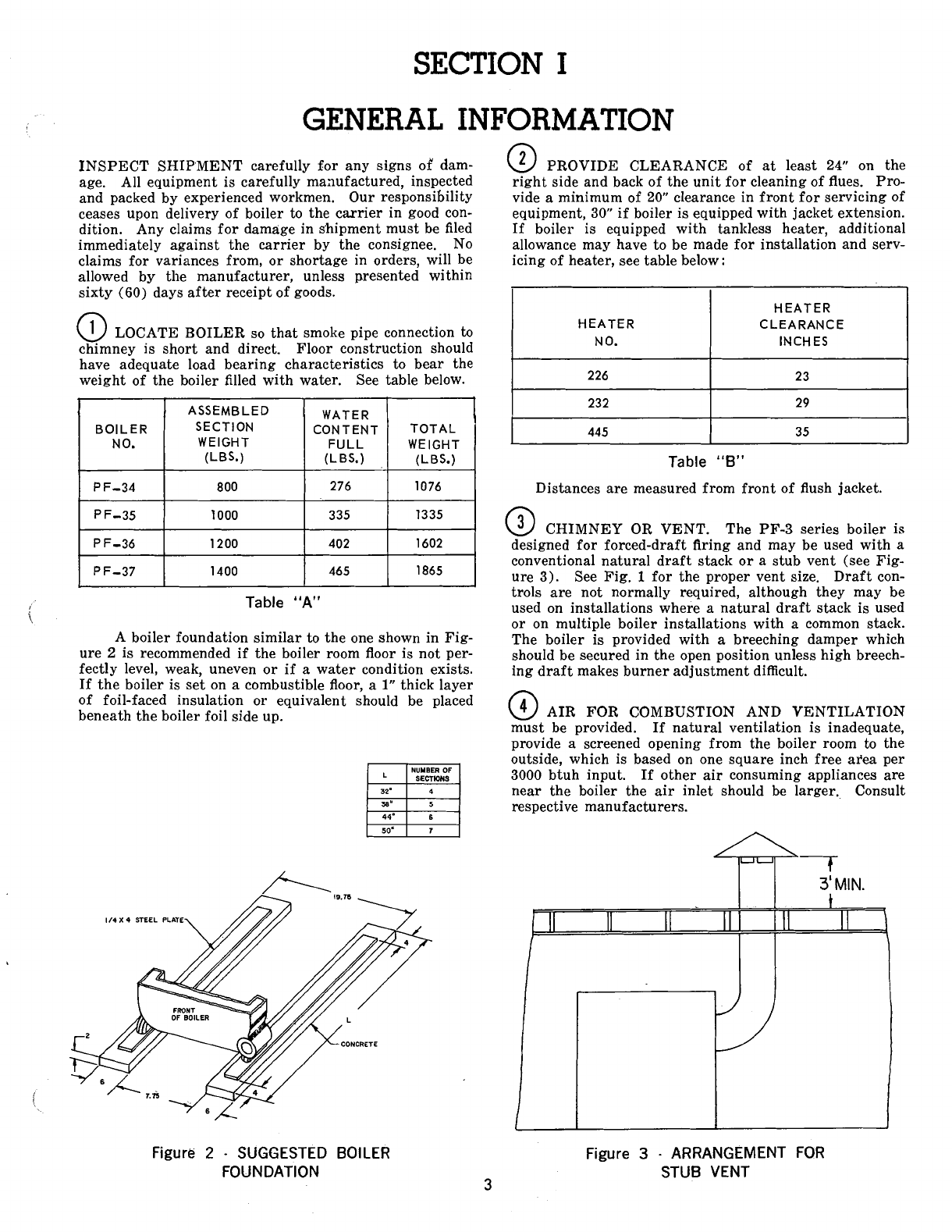
LOCATE BOILER so that smoke pipe connection
to
chimney is short and direct. Floor construction should
have adequate load bearing characteristics to bear the
weight of the boiler filled with water. See table below.
HEATER
N
0.
226
232
445
HEATER
CLEARANCE
INCHES
2 3
29
35
TOTAL
WEIGHT
BOILER
N
0.
Table "B"
Distances are measured from front of flush jacket.
@
CHIMNEY OR VENT. The PF-3 series boiler is
designed for forced-draft firing and may be used with a
conventional natural draft stack or a stub vent (see Fig-
ure
3).
See Fig.
1
for the proper vent size. Draft con-
trols are not normally required, although they may be
Table "A"
used on installations where a natural draft stack is used
or on multiple boiler installations with a common stack.
A boiler foundation similar to the one shown in Fig- The boiler is provided with
a
breeching damper which
ure
2
is recommended if the boiler room floor is not Per- should be secured in the open position unless high breech-
fectly level, weak, uneven or if a water condition exists. ing draft makes burner adjustment difficult.
If the boiler is set on a combustible floor, a
1"
thick layer
of foil-faced insulation or equivalent should be placed
beneath the boiler foil side up.
@
AIR FOR COMBUSTION AND VENTILATION
must be provided. If natural ventilation is inadequate,
provide a screened opening from the boiler room to the
outside, which is based on one square inch free afea per
rl
3000
btuh input. If other air consuming appliances are
near the boiler the air inlet should be larger. Consult
respective manufacturers.
44.
50.
114
X
4
STEEL
PLATE
/
Figure
2
-
SUGGESTED BOILER Figure
3
-
ARRANGEMENT FOR
FOUNDATION STUB VENT
3
(LBS.)
1076
1335
1602
1865
P
F-34
P
F-35
P
F-36
P
F-37
ASSEMBLED
SECTION
WEIGHT
WATER
CONTENT
FULL
(LBS.)
800
1000
1200
1400
(LBS.)
276
335
402
465
SECTION I1
INSTALLATION INSTRUCTIONS
a
Place boiler assembly on foundation provided. Shim
if necessary. The tie rod nuts should then be loosened
until finger tight.
"INSTALLATION OF BUILT-IN HEATERS AND
HEATER OPENING COVER PLATES"
@
INSTALLATION OF BUILT-IN DOMESTIC WA-
TER HEATER if furnished.
a. Slip Rubber Gasket over Heater Coil and place
against Heater Mounting Plate so that holes in
Gasket are in line with holes in Heater Mounting
Plate.
b. Install Built-in Heater Coil through openihg in
Front Section into the upper nipple port for water
boilers or the lower nipple port for steam boilers.
(See Fig.
4).
c. Secure the Heater Mounting Plate with
3/8
Hex
Head Cap Screws and Flat Washers (if furnished).
Snug all screws before final tightening.
d. Attach the Tapped Heater Cover Plate with Rubber
Gasket to the remaining opening in the Front Sec-
tion. Secure with
3/8"
Hex Hd. Cap Screws and
Flat Washers (if furnished). Snug all screws before
tightening.
@
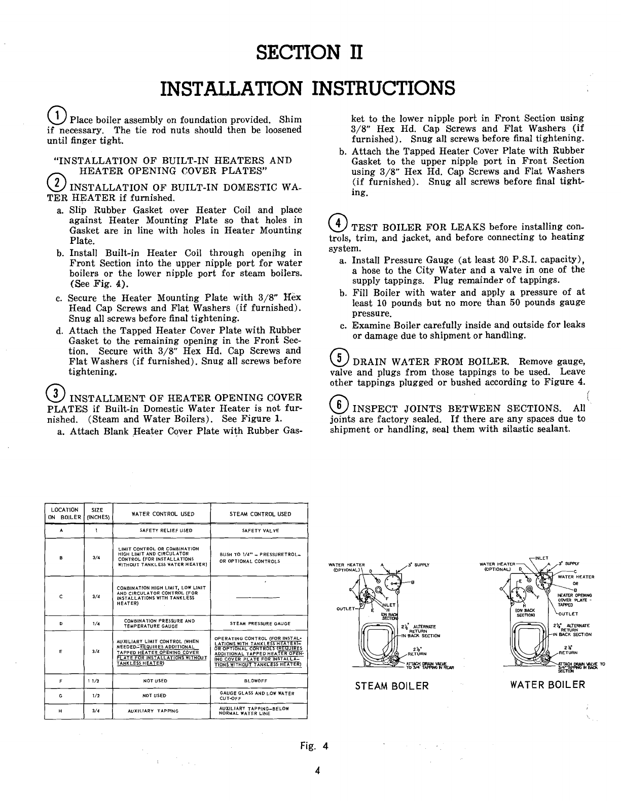
INSTALLMENT OF HEATER OPENING COVER
PLATES if Built-in Domestic Water Heater is not fur-
nished. (Steam and Water Boilers). See Figure
l.
a. Attach Blank Heater Cover Plate with Rubber Gas-
LlMlT CONTROL OR COMBINATION
Iml
HlGH LlMlT AND CIRCULATOR
CONTROL (FOR INSTALLATIONS
WITHOUT
TANKLESS
WATER
HEATER)
LOCATION
ON BOILER
A
COMBINATION HlGH LIMIT, LOW LlMlT
AND CIRCULATOR CONTROL (FOR
INSTALLATIONS WITH TANKLESS
1 1
HEATER)
SIZE
(INCHES)
1
AUXILIARY LlMlT CONTROL (WHEN
I
NEEDED-TEQUIRES ADDITIONAL
TAPPED HEATER OPENING COVER
P~OUT
TANKLESS HEATER)
WATER
'ONTRoL
SAFETY RELIEF USED
D
F (11/2
1
NOT USED
COMBINATION PRESSURE AND
TEMPERATURE GAUGE
BUSH TO 1/4"
-
PRESSURETROL-
OR OPTIONAL CONTROLS
G
H
STEAM PRESSURE GAUGE
d
GAUGE GLASS AND LOW WATER
CUT-OFF
1/2
3/4
ket to the lower nipple port in Front Section using
3/8"
Hex Hd. Cap Screws and Flat Washers (if
furnished). Snug all screws before final tightening.
b. Attach the Tapped Heater Cover Plate with Rubber
Gasket to the upper nipple port in Front Section
using
3/8"
Hex Hd. Cap Screws and Flat Washers
(if furnished). Snug all screws before final tight-
ing.
NOT USED
AUXILIARY TAPPING
@
TEST BOILER FOR LEAKS before installing con-
trols, trim, and jacket, and before connecting to heating
system.
a. Install Pressure Gauge (at least
30
P.S.I. capacity),
a hose to the City Water and a valve in one of the
supply tappings. Plug remainder of tappings.
b. Fill Boiler with water and apply a pressure of at
least
10
pounds but no more than
50
pounds gauge
pressure.
c. Examine Boiler carefully inside and outside for leaks
or damage due to shipment or handling.
DRAIN WATER FROM BOILER. Remove gauge,
valve and plugs from those tappings to be used. Leave
other tappings plugged or bushed according to Figure
4.
@
INSPECT JOINTS BETWEEN SECTIONS. All
joints are factory sealed. If there are any spaces due to
shipment or handling, seal them with silastic sealant.
WATER HEATER A
,3'
SUPPLY
(OPTIONAL)=
IN BACK SECTION
1nw
OR9UI
VUkE
rnw~Amws~w
STEAM BOILER WATER BOILER
-
-
AUXILIARY TAPPING-BELOW
NORMAL WATER LINE
I
Fig.
4
4
(1)
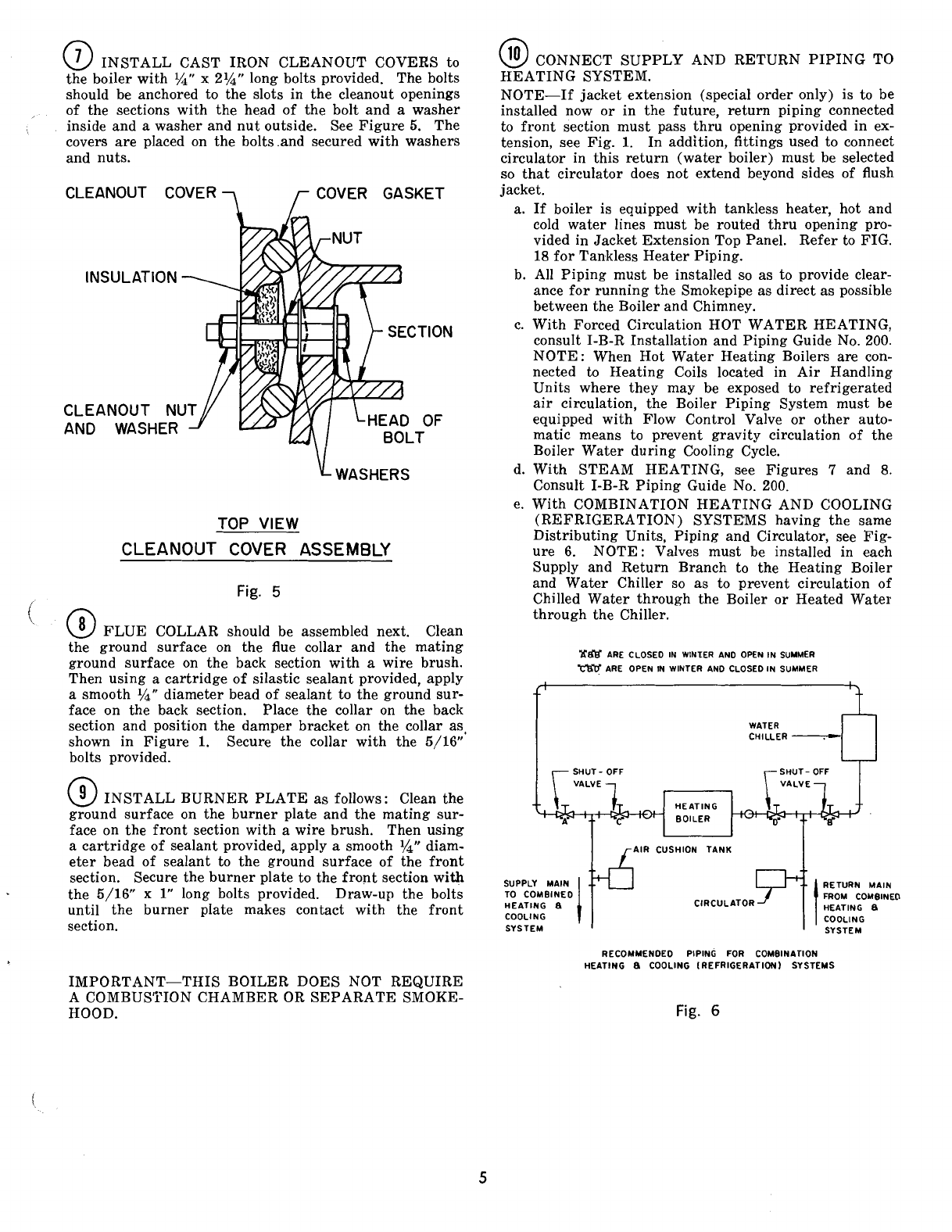
INSTALL CAST IRON CLEANOUT COVERS to
the boiler with
x"
x
2%''
long bolts provided. The bolts
should be anchored to the slots in the cleanout openings
of the sections with the head of the bolt and
a
washer
inside and a washer and nut outside. See Figure 5. The
covers are placed on the bolts.and secured with washers
and nuts.
CLEANOUT COVER
7
r
COVER GASKET
INSULATION
CLEANOUT NUT
AND WASHER
WASHERS
TOP VIEW
CLEANOUT COVER ASSEMBLY
Fig.
5
'
@
FLUE COLLAR should be assembled next. Clean
the ground surface on the flue collar and the mating
ground surface on the back section with
a
wire brush.
Then using a cartridge of silastic sealant provided, apply
a smooth
1/4"
diameter bead of sealant to the ground sur-
face on the back section. Place the collar on the back
section and position the damper bracket on the collar as,
shown in Figure
1.
Secure the collar with the 5/16"
bolts provided.
@
INSTALL BURNER PLATE as follows: Clean the
ground surface on the burner plate and the mating sur-
face on the front section with a wire brush. Then using
a cartridge of sealant provided, apply a smooth
s"
diam-
eter bead of sealant to the ground surface of the front
section. Secure the burner plate to the front section with
the 5/16 x
1"
long bolts provided. Draw-up the bolts
until the burner plate makes contact with the front
section.
IMPORTANT-THIS BOILER DOES NOT REQUIRE
A COMBUSTION CHAMBER OR SEPARATE SMOKE-
HOOD.
@)
CONNECT SUPPLY AND RETURN PIPING TO
HEATING SYSTEM.
NOTE-If jacket extension (special order only) is to be
installed now or in the future, return piping connected
to front section must pass thru opening provided in ex-
tension, see Fig.
1.
In addition, fittings used to connect
circulator in this return (water boiler) must be selected
so that circulator does not extend beyond sides of flush
jacket.
a. If boiler is equipped with tankless heater, hot and
cold water lines must be routed thru opening pro-
vided in Jacket Extension Top Panel. Refer to FIG.
18 for
Tankless Heater Piping.
b. All Piping must be installed so as to provide clear-
ance for running the Smokepipe as direct as possible
between the Boiler and Chimney.
c. With Forced Circulation HOT WATER HEATING,
consult I-B-R Installation and Piping Guide No.
200.
NOTE: When Hot Water Heating Boilers are con-
nected to Heating Coils located in Air Handling
Units where they may be exposed to refrigerated
air circulation, the Boiler Piping System must be
equipped with Flow Control Valve or other auto-
matic means to prevent gravity circulation of the
Boiler Water during Cooling Cycle.
d. With STEAM HEATING, see Figures
7
and 8.
Consult I-B-R Piping Guide No.
200.
e. With COMBINATION HEATING AND COOLING
(REFRIGERATION) SYSTEMS having the same
Distributing Units, Piping and Circulator, see Fig-
ure 6. NOTE: Valves must be installed in each
Supply and Return Branch to the Heating Boiler
and Water Chiller so as to prevent circulation of
Chilled Water through the Boiler or Heated Water
through the Chiller.
Hm
ARE CLOSED IN WINTER AND OPEN IN SUMMER
ARE OPEN IN WINTER AND CLOSED IN SUMMER
WATER
CHILLER
--Ic
n
I
SHUT- OFF
r
SHUT- OFF
I
VALVE
HEATING
A
d
BOILER
I
[AIR CUSHION TANK
I
SUPPLY MAIN
If"
RETURN MAIN
TO COMBINED CIRCULATOR FROM COMBlNECl
HEATING
8
HFATING
I3
COOLING
SYSTEM
'1
,
,
.;;;;;
M-
-
COOLING
RECOMMENDED PIPING FOR COMBINATION
HEATING
8
COOLING IREFRIGERATION) SYSTEMS
Fig.
6
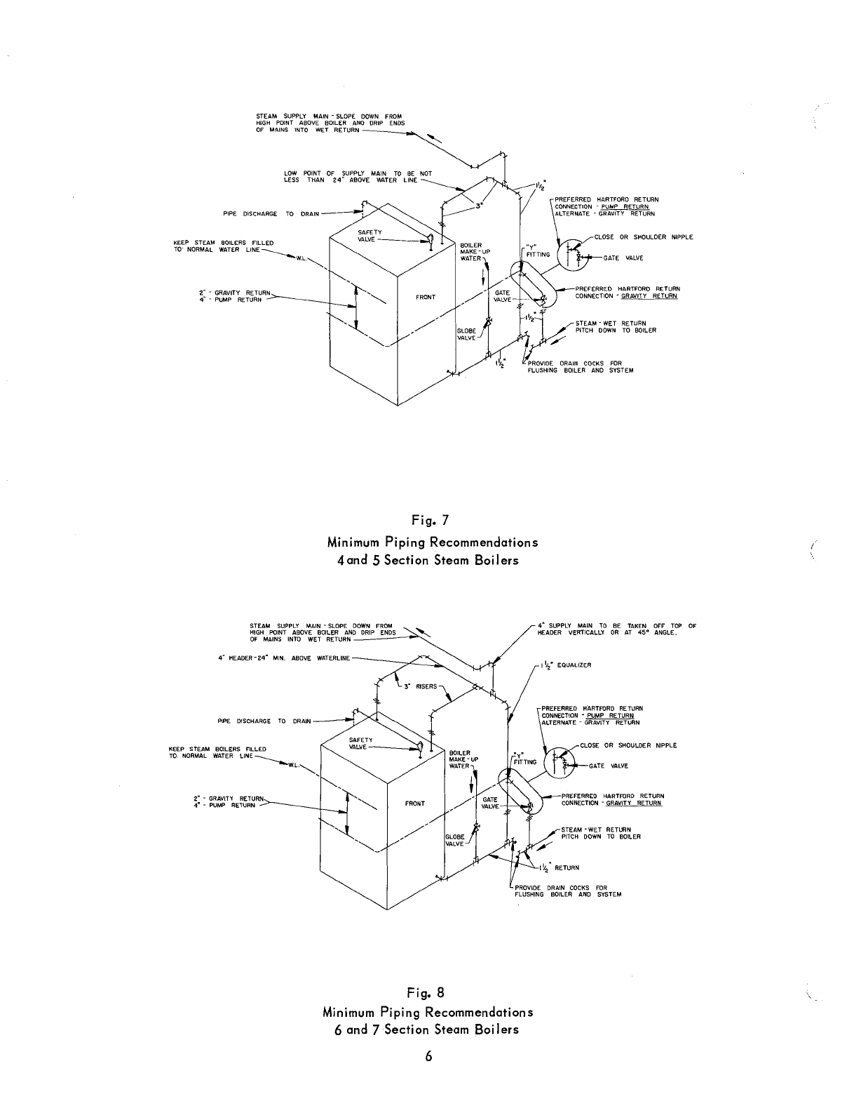
STEAM SUPPLY MAIN -SLOPE DOWN FROM
HIGH POINT ABOVE BOILER AN0 DRIP ENDS
OF MCllNS INTO WET RETURN
LOW POINT OF SUPPLY MAIN TO BE NOT
LESS THAN 29' ABOVE WATER LlNE
PIPE DISCHARGE TO DRAIN
KEEP STEAM BOILERS FILLED CLOSE OR SHOULOER NIPPLE
TO NORMAL WATER LlNE
1W.L
2"
-
GRAVITY RETURN PREFERRED HARTFORO RETURN
4"
-
PUMP RETURN CONNECTION
'
GRAVITY RETURN
STEAM
-
WET RETURN
PITCH DOWN TO BOILER
Fig.
7
Minimum Piping Recommendations
4
and
5
Section Steam Boilers
4"
SUPPLY MAIN TO BE TAKEN OFF TOP OF
WADER VERTICALLY OR AT
45'
ANGLE.
4"
HEADER -24. MIN. ABOVE WATERLINE
PREFERRED HARTFORD RETURN
KEEP STEAM BOILERS FILLED CLOSE OR SHOULDER NIPPLE
TO NORMAL WATER LlNE
2"
-
GRAVITY RETURN PREFERRED HARTFORD RETURN
4.
-
PUMP RETURN
+
CONNECTION
-
GRAVITY RETURN
STEAM -WET RETURN
PITCH DOWN TO BOILER
PROVIDE DRAIN COCKS FOR
FLUSHING BOILER AND SYSTEM
Fig.
8
Minimum Piping Recommendations
6
and
7
Section Steam Boilers
6
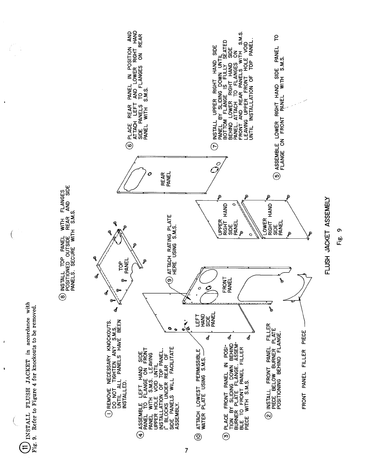
@)
INSTALL FLUSH JACKET
in
accordance
with
Fig.
9.
Refer to Figure
4
for knockouts to be removed.
@)
INSTALL TOP PANEL WlTH FLANGES
POSITIONED OUTSIDE REAR AND SlDE
PANELS. SECURE WlTH S.M.S.
@
REMOVE NECESSARY KNOCKOUTS.
DO NOT TIGHTEN ANY S.M.S.
UNTIL ALL PANELS HAVE BEEN TOP
PANEL
INSTALLED.
@ASSEMBLE LEFT HAND SIDE
PANEL TO FLANGE ON FRONT
PANEL WITH S.M.S. LEAVING
UPPER HOLE VOlD UNTIL
INSTALLATION OF TOP PANEL.
I"
BLOCKS UNDER REAR OF
SlDE PANELS WILL FACILITATE
ASSEMBLY.
@I
ATTACH LOWEST
WATER PLATE USING S.M.S.
@.
@
PLACE FRONT PANEL IN POSI-
TION BY SLIDING DOWN BEHIND
BURNER PLATE FLANGE. ASSEM-
BLE TO FRONT PANEL FILLER
PIECE WITH S.M.S.
&
D
ATTACH RATING PLATE
I
HERE USING S.M.S.
INSTALL FRONT PANEL FILLER
PIECE BELOW BURNER PLATE
POSITIONING BEHIND FLANGE.
FRONT PANEL FILLER PIECE
-----k?
S-.
'3
REAR
PANEL
UPPER
RlGHT HAND
PANEL
@
PLACE REAR PANEL IN POSITION AND
ATTACH LEFT AND LOWER RlGHT HAND
SlDE PANELS TO FLANGES ON REAR
PANEL WlTH S.M.S.
@
INSTALL UPPER RlGHT HAND SlDE
PANEL BY SLIDING DOWN UNTIL
BOTTOM FLANGE IS FULLY SEATED
BEHIND LOWER RlGHT HAND SlDE
PANEL. ATTACH TO FLANGES ON
FRONT AND REAR PANELS WITH S.M.S.
LEAVING UPPER FRONT HOLE VOlD
UNTIL INSTALLATION OF TOP PANEL.
LUWtK
RlGHT HAND
'%
1
@
ASSEMBLE LOWER RIGHT HAND SlDE PANEL
PANEL FLANGE ON FRONT PANEL WITH S.M.S.
FLUSH JACKET ASSEMBLY
Fig.
9
@
INSTALLATION OF TRIM AND CONTROLS
FOR WATER BOILERS. (See Figure
4
for Control
Locations.)
a. Screw COMBINATION ALTITUDE GAUGE AND
THERMOMETER into
%"
tapping. Tighten by
wrench applied to square shank back of gauge. DO
NOT APPLY PRESSURE ON GAUGE CASE since
this may destroy calibration of gauge.
b. RELIEF VALVE-Install in
1"
Tapping next to
3"
Supply Tapping in Front Section using fittings pro-
vided.
CAUTION
:
Safety Relief Valve should be piped to
and open drain-full size of discharge outlet on
Relief Valve and without any provision of "shut-off"
between the Relief Valve and discharge into drain.
c. Install Hydronic Controls in their designated tap-
pings.
@
INSTALLATION OF TRIM AND CONTROLS
FOR STEAM BOILERS. (See Figure
4
for control
locations.)
a.
Screw Combination Pressure Vacuum Gauge into
designated
$"
tapping. Tighten by wrench applied
to square shank on back of gauge. Do not apply
pressure on gauge case since this may destroy cali-
bration of gauge.
b. SAFETY VALVE. Install in
1"
Tapping next to
3"
Supply Tapping in Front Section.
CAUTION: Safety Valve should be piped to an
open drain-full size of discharge outlet on Safety
Valve and without any provision of "shut-off" be-
tween the Safety Valve and discharge into drain.
c. Install Pressure Limit Control with
1/4"
Pig Tail
Syphon into Heater Cover Plate Tapping bushed
3/4"
to
G".
d. Install Operating Control (supplied with Tankless
Heater equipped boilers only) in designated tapping.
e. Install Gauge Glass and Low Water Cut-off (if fur-
nished) in
y2"
tappings on left side of Front Sec-
tion.
@)
INSTALL SMOKEPIPE so that connection
to
Chimney or vent is short and direct.
a. Install in accordance with LOCAL FIRE ORI-
NANCES.
b. Smokepipe must not be smaller than the
8"
dia. flue
collar. See Fig.
1.
For Stub Vent installation see Fig.
3,
if connected
to chimney.
c. Do not connect into same leg of Chimney serving an
open fireplace.
d. Inspect Chimney for obstructions or restrictions
which should be removed. Clean Chimney if neces-
sary.
e. Smokepipe should slope upward from Boiler to
Chimney not less than one inch in four feet. Smoke-
.
pipe must be securely supported so as to maintain,
proper clearances from combustible materials and
to prevent separation of joints.
f. Insert Smokepipe into but not beyond inside wall of
Chimney Flue Lining. Pipe should be installed
above the extreme bottom of Chimney so as to pre-
vent stoppage.
y.
Seal between Smokepipe and Chimney connection to
prevent draft leakage.
0
INSTALL ROOM THERMOSTAT on an inside
wall about four feet above floor. Never install Thermo-
stat on an outside wail or where it will be influenced by
drafts, hot or cold water pipes, lighting fixtures, tele-
vision, rays of the sun, or near a fireplace. Keep large
furniture away from Thermostat so there will be free
movement of room air around this Control.
@
OIL BURNER INSTALLATION. Bolt burner to
mounting plate with nuts and washers packed in boiler
parts carton. REFER TO BURNER INSTALLATION
and SERVICE MANUAL form No.
52004.
I
\
@)
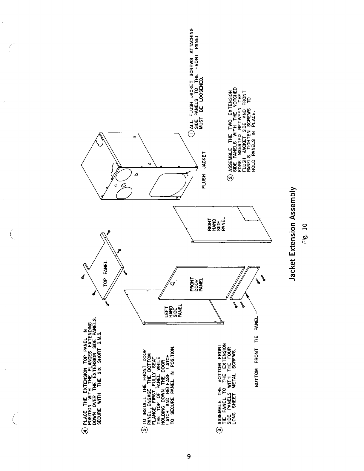
BOILER with JACKET EXTENSION refer to
Figure
10
for assembly instructions.
h
INSTALL ELECTRIC WIRING in accordance with
NATIONAL ELECTRICAL CODE and Local Regula-
tions.
a.
A separate ELECTRICAL CIRCUIT should be run
from Meter with a Fused Disconnect Switch in
this Circuit.
See Figures
11
thru
17
for appropriate wiring dia-
gram.
@
PLACE THE EXTENSION TOP PANEL IN
POSITION WlTH THE FLANGES EXTENDING
DOWN OVER THE EXTENSION SlDE PANELS.
SECURE WlTH THE SIX SHORT S.M.S.
TO INSTALL THE FRONT DOOR
'PANEL
,
ENGAGE THE BOTTOM
FLANGE FIRST, FULLY SEAT
THE TOP OF PANEL WHILE
HOLDING DOWN THE DOOR
LATCH AND RELEASE LATCH
TO SECURE PANEL IN POSITION.
@
ASSEMBLE THE BOTTOM FRONT
TIE PANEL TO THE EXTENSION
SIDE
PANELS
WITH
THE
FOUR
LONG SHEET METAL SCREWS.
BOTTOM FRONT TIE PANEL
8
RIGHT
HAND
SlDE
PANEL
FLUSH JACKET
--
ALL FLUSH JACKET SCREWS ATTACHING
SlDE PANELS TO THE FRONT PANEL
MUST BE LOOSENED.
@
ASSEMBLE THE TWO EXTENSION
SlDE PANELS WlTH THE NOTCHED
EDGE INSERTED BETWEEN THE
FLUSH JACKET SlDE AND FRONT
PANELS. TIGHTEN SCREWS TO
HOLD PANELS IN PLACE.
Jacket Extension Assembly
Fig.
10
THERMOSTAT
LOW WATER
n
HONEYWELL PA 404A
CUTOFF PRESSURE LIMIT
CONTROL
IGNITION-
TRANSFORMER
HOT
1
LlNE
'
I
NEUTRAL
E$go'S:D
SWITCH
I I
,
I,(/I IMC
UtLAT
VALVE
HONEYWELL R8184
PRIMARY CONTROL
'
1
.,-...a-
,.-.
...
=
0
-
;
W-
VO
-
Fig.
11
?o
TFOI.
FO
OIL BURNER
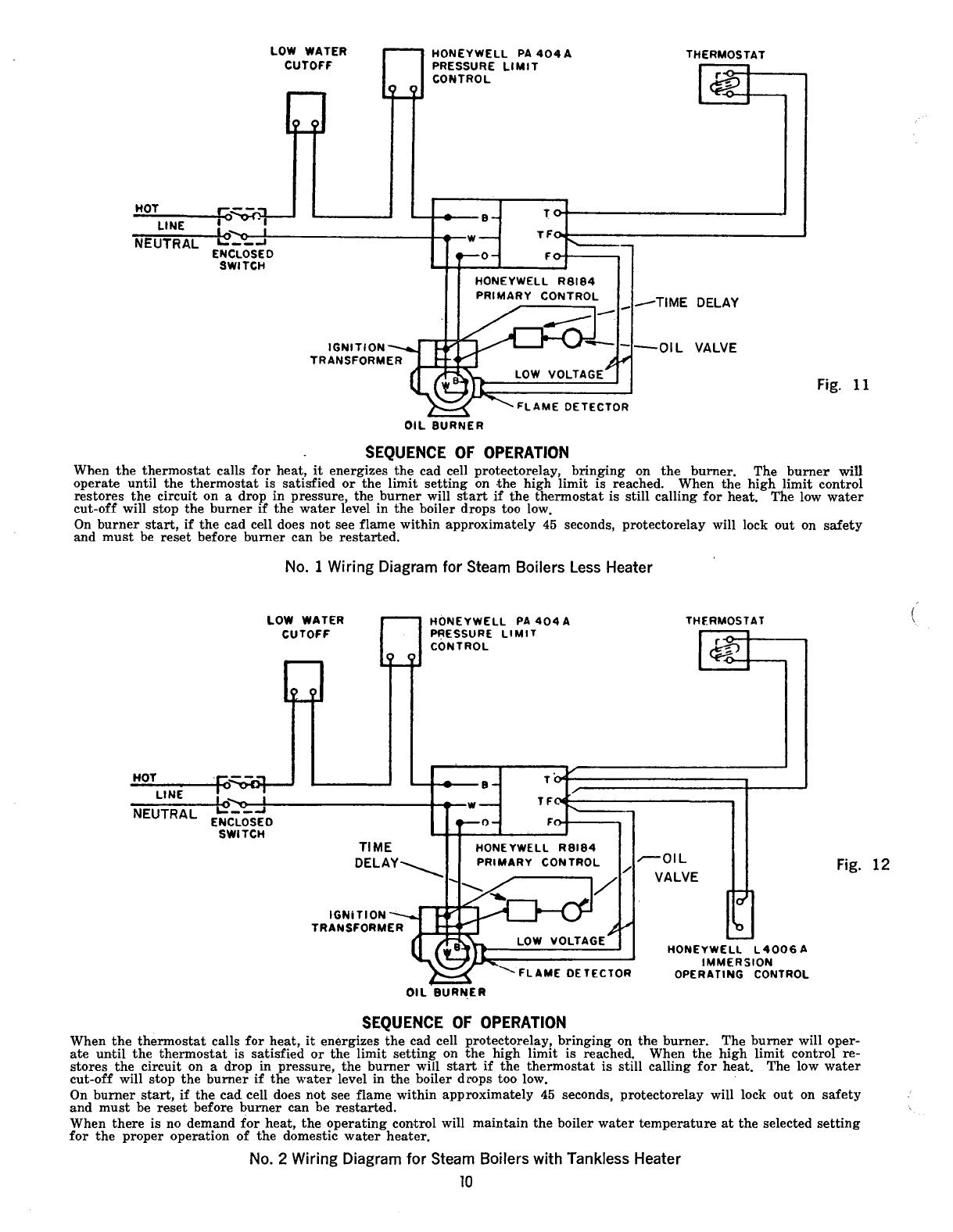
SEQUENCE OF OPERATION
When the thermostat calls for heat, it energizes the cad cell protectorelay, bringing on the burner. The burner
will
operate until the thermostat is satisfied or the limit setting on ,the high limit is reached. When the high limit control
restores the circuit on a drop in pressure, the burner will start if the thermostat is still calling for heat. The low water
cut-off will stop the burner if the water level in the boiler drops too low.
On burner start, if the cad cell does not see flame within approximately
45
seconds, protectorelay will lock out on safety
and must be reset before burner can be restarted.
No.
1
Wiring
Diagram
for
Steam
Boilers
Less
Heater
TRANSFORM
IMMERSION
OPERATING CONTROL
OIL BURNER
SEQUENCE OF OPERATION
When the thermostat calls for heat, it energizes the cad cell protectorelay, bringing on the burner. The burner will oper-
ate until the thermostat is satisfied or the limit setting on the high limit is reached. When the high limit control re-
stores the circuit on a drop in pressure, the burner will start if the thermostat is still calling for heat. The low water
cut-off will stop the burner if the water level in the boiler drops too low.
On burner start, if the cad cell does not see flame within approximately
45
seconds, protectorelay will lock out on safety
and must be reset before burner can be restarted.
When there is no demand for heat, the operating con,trol will maintain the boiler water temperature at the selected setting
for the proper operation of the domestic water heater.
HONEYWELL PA 404A THERMOSTAT
PRESSURE LIMIT
CONTROL
LOW WATER
CUTOFF
Fig.
12
-
HOT
-
-
0
-
LlNE
I
NEUTRAL
E~~oS<O
SWITCH
I
I
b
Q?
No.
2
Wiring
Diagram
for
Steam
Boilers
with
Tankless
Heater
10
HONEYWELL L40818
IMMERSION CIRCULATOR
AND
LIMIT CONTROL
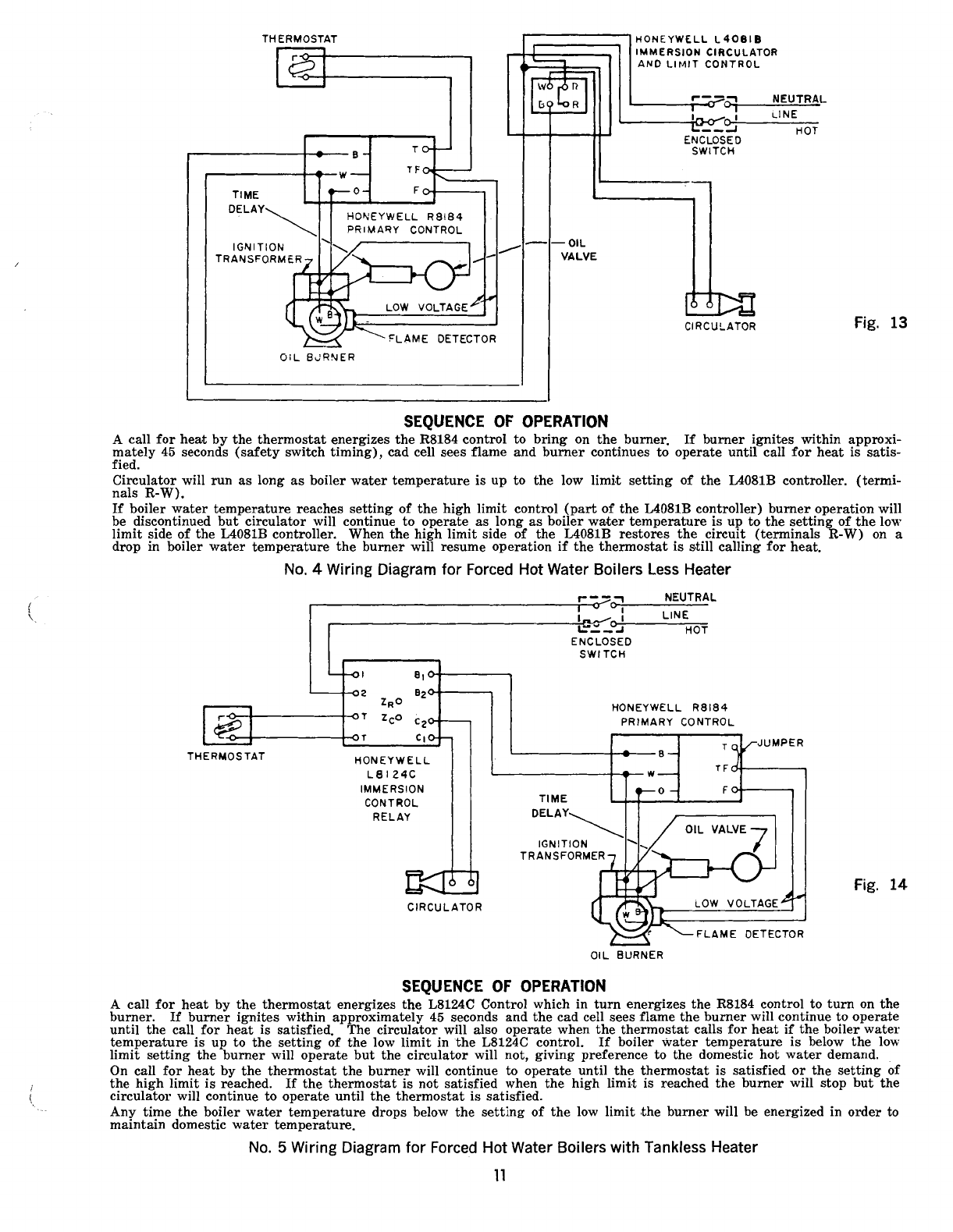
Fig.
13
SEQUENCE OF OPERATION
A call for heat by the thermostat energizes the R8184 control to bring on the burner. If burner ignites within approxi-
mately 45 seconds (safety switch timing), cad cell sees flame and burner continues to operate until call for heat is satis-
fied.
Circulator will run as long as boiler water temperature is up to the low limi,t setting of the L4081B controller. (termi-
nals R-W).
If boiler water temperature reaches setting of the high limit control (part of the L4081B controller) burner operation will
be discontinued but circulator will continue to operate as long as boiler water temperature is up to the setting of the low
limit side of the L4081B controller. When the high limit side of the L4081B restores the circuit (terminals R-W) on a
drop in boiler water temperature the burner will resume operation if the thermostat is still calling for heat.
No.
4
Wiring Diagram for Forced Hot Water Boilers Less Heater
HONEYWELL RE184
TH
IMMERSION
TRANSFORME
Fig.
14
CIRCULATOR
OIL BURNER
SEQUENCE OF OPERATION
A
call for heat by the thermostat energizes the L8124C Control which in turn energizes the R8184 control to turn on the
burner. If burner ignites within approximately 45 seconds and the cad cell sees flame the burner will continue to operate
until the call for heat is satisfied. The circulator will also operate when the thermostat calls for heat if the boiler water
temperature is up to the setting of the low limit in the L8124C control.
If
boiler water temperature is below the low
limit setting the burner will operate but the circulator will not, giving preference to the domestic hot water demand.
On call for heat by the thermostat the burner will continue to operate until the thermostat is satisfied or the setting of
the high limit is reached. If the thermostat is not satisfied when the high limit is reached the burner will stop but the
circulator will continue to operate until the thermostat is satisfied.
Any time the boiler water temperature drops below the setthg of the low limit ,the burner will be energized in order to
maintain domestic water temperature.
No.
5
Wiring Diagram for Forced Hot Water Boilers with Tankless Heater
-
--I
NEUTRAL
T
LINE
-
K0d
HOT
ENCLOSED
SW
l
TCH
HONEYWELL
L8124C
IMMERSION
CONTROL
RELAY
THERMOSTAT
F
i
I
II
1
RELAY
CIRCULATOR
THERMOSTAT
CIRCULATOR
AT
I
HONEYWELL
CIRCULATOR
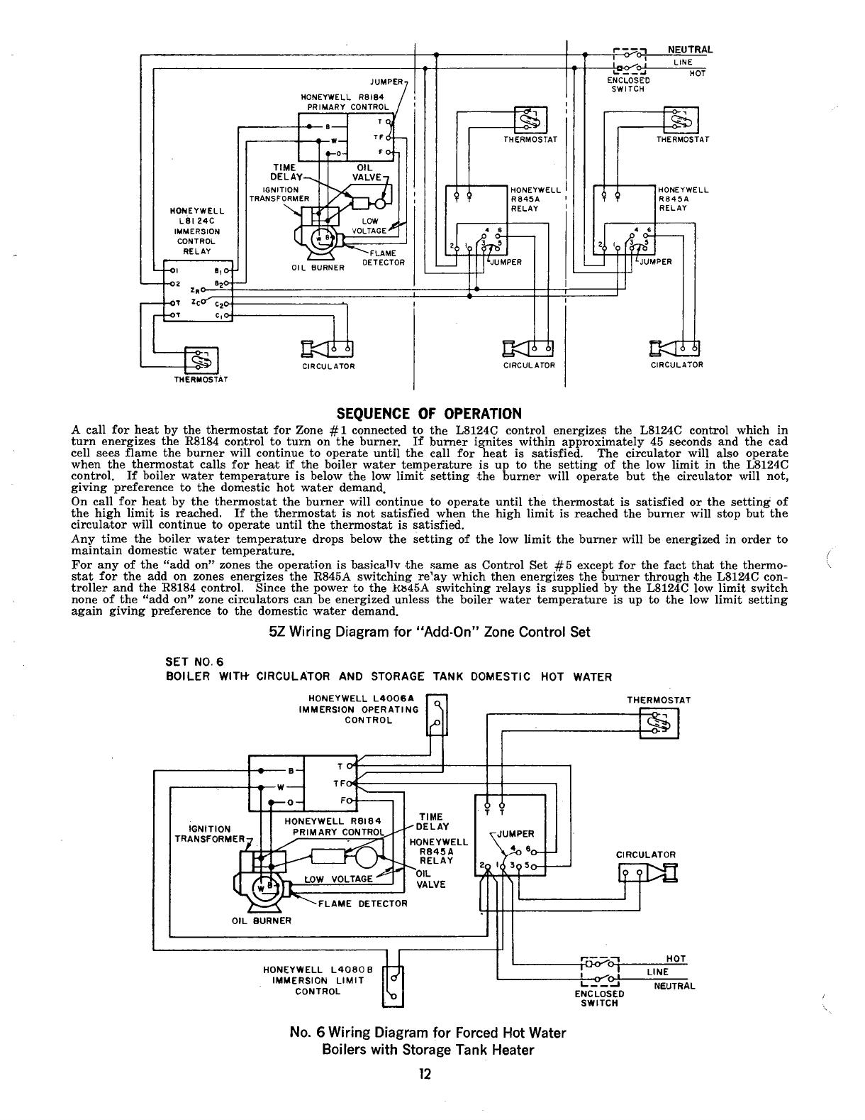
SEQUENCE
OF
OPERATION
A
call for heat by the thermostat for Zone
#1
connected to the L8124C control energizes the L8124C control which in
turn energizes the R8184 control to turn on the burner. If burner ignites within approximately 45 seconds and the cad
cell sees flame the burner will continue to operate until the call for heat is satisfied. The circulator will also operate
when the thermostat calls for heat if the boiler water temperature is up to the setting of the low limit in the L8124C
control. If boiler water temperature is below the low limit setting ,the burner will operate but the circulator will not,
giving preference to the domestic hot water demand.
On call for heat by the thermostat the burner will continue to operate until the thermostat is satisfied or the setting of
the high limit is reached. If the thermostat is not satisfied when the high limit is reached the burner will stop but the
circulator will continue to operate until the thermostat is satisfied.
Any time the boiler water temperature drops below the setting of the low limit the burner will be energized in order to
maintain domestic water temperature.
i
For any of the "add on" zones the operation is basicallv the same as Control Set #5 except for the fact that the thermo-
stat for the add on zones energizes the R845A switching re,ay which then energizes the burner through -the L8124C con-
troller and the R8184 control. Since the power to the Ka45A switching relays is supplied by the L8124C low limit switch
none of the "add on" zone circulators can be energized unless the boiler water temperature is up to the low limit setting
again giving preference to the domestic water demand.
52 Wiring Diagram for "Add-On" Zone Control Set
SET NO.
6
BOILER WITH CIRCULATOR AND STORAGE TANK DOMESTIC HOT WATER
HONEYWELL L4006A
I,(
THERMOSTAT
IMMERSION OPERATING
CONTROL
No.
6
Wiring Diagram for Forced Hot Water
Boilers with Storage Tank Heater
12
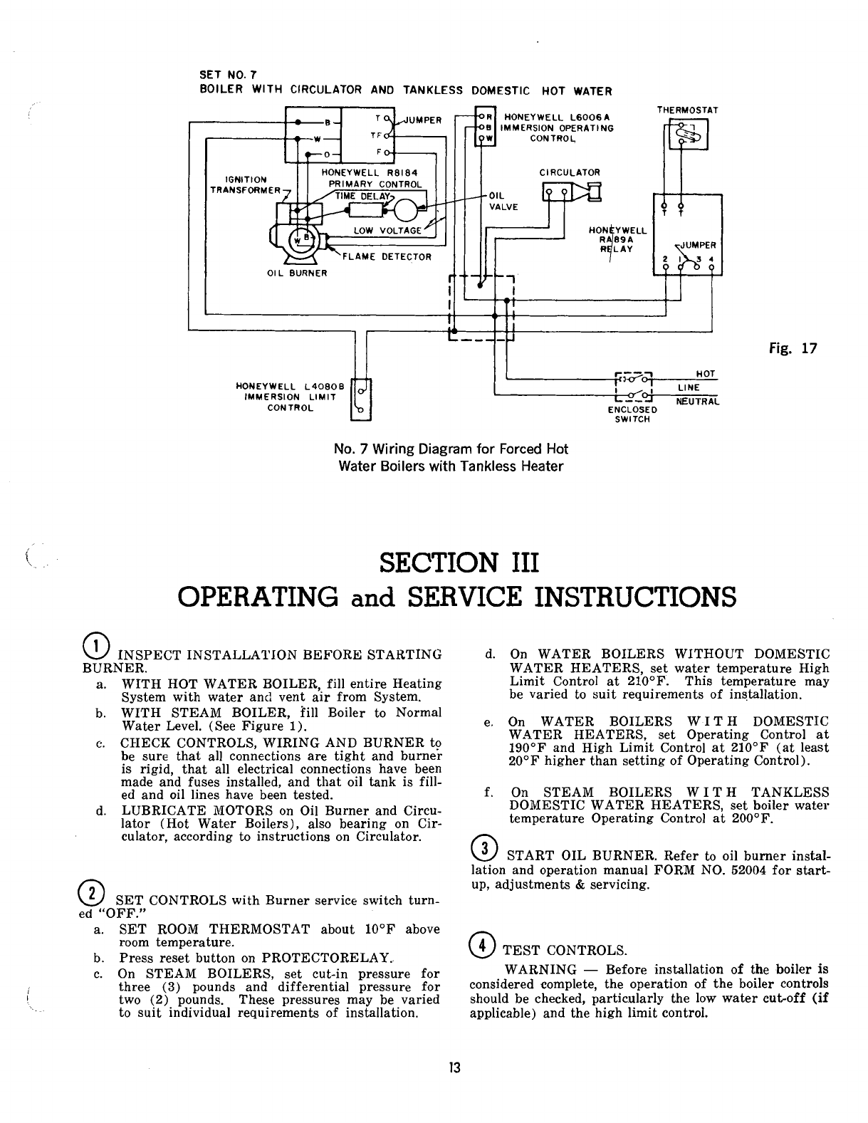
SET NO.
7
BOILER WITH CIRCULATOR AND TANKLESS DOMESTIC HOT WATER
IGNITION
TRANSFORME
IGNITION
HONEYWELL
R8184
OIL
BURNER
OR
HONEYWELL
L6006A
-0B
I
IMMERSION
OPERATING
f"
CONTROL
CIRCULATOR
VALVE
-OIL
7P
THERMOSTAT
HONEYWELL
L4080B
IMMERSION
LIMIT
CONTROL
HOT
NEUTRAL
ENCLOSED
No.
7
Wiring Diagram for Forced Hot
Water Boilers with Tankless Heater
SECTION I11
OPERATING
and
SERVICE INSTRUCTIONS
Fig.
17
@
INSPECT INSTALLATION BEFORE STARTING d. On WATER BOILERS WITHOUT DOMESTIC
BURNER. WATER HEATERS, set water temperature High
a. WITH HOT WATER BOILER, fill entire Heating Limit Control at 210°F. This temperature may
System with water and vent air from System. be varied to suit requirements of installation.
b.
WITH
STEAM BOILER, fill Boiler to Normal
Water Level. (See Figure 1).
c.
CHECK CONTROLS, WIRING AND BURNER to
be sure that all connections are tight and burner
is rigid, that all electrical connections have been
made and fuses installed, and that oil tank is fill-
ed and oil lines have been tested.
d. LUBRICATE MOTORS on Oil Burner and Circu-
lator (Hot Water Boilers), also bearing on Cir-
culator, according to instructions on Circulator.
@
SET CONTROLS with Burner service switch turn-
ed "OFF."
a. SET ROOM THERMOSTAT about 10°F above
room temperature.
b. Press reset button on PROTECTORELAY..
c. On STEAM BOILERS, set cut-in pressure for
three
(3)
pounds and differential pressure for
two (2) pounds. These pressures may be varied
to suit individual requirements of installation.
e. On WATER BOILERS WITH DOMESTIC
WATER HEATERS, set Operating Control at
190°F and High Limit Control at 210°F (at least
20°F higher than setting of Operating Control).
f. On STEAM BOILERS WITH TANKLESS
DOMESTIC WATER HEATERS, set boiler water
temperature Operating Control at 200°F.
@
START OIL BURNER. Refer to oil burner instal-
lation and operation manual FORM NO. 52004 for start-
up, adjustments
&
servicing.
@
TEST CONTROLS.
WARNING
-
Before installation of the boiler
is
considered complete, the operation of the boiler controls
should be checked, particularly the low water cut-off (if
applicable) and the high limit control.
(5)
CLEAN STEAM HEATING SYSTEM for trouble
free operation. Oil, greases and sediments which accu-
mulate in a new boiler and piping must be removed from
the system in order to prevent an unsteady water line
and carry over of water into the Supply Main above boil-
er.
a. Operate the boiler with steam in the entire system
for a few days allowing the condensate to return to
the boiler. If the condensate can temporarily be
wasted, operate boiler only for the length of time
it takes for condensate to run clear. If the latter
cannot be achieved or if the condensate is return-
ed to the boiler, boilout the boiler using the SUR-
FACE BLOWOFF connection, see Figure 4.
1). Drain boiler until water is just visible in gauge
glass. Run temporary
1%"
pipe line from the Surface
Blowoff Connection to an open drain or some other loca-
tion where hot water may be discharged safely. Do not
install valve in this line.
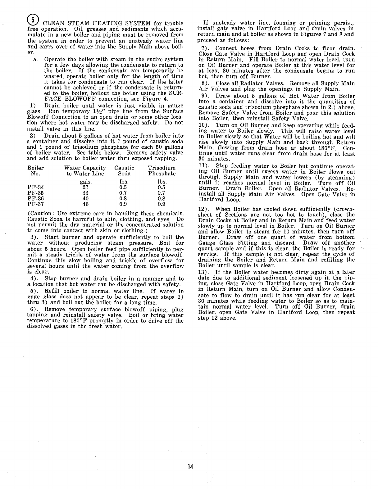
2). Drain about 5 gallons of hot water from boiler into
a container and dissolve into it
1
pound of caustic soda
and
1
pound of trisodium phosphate for each 50 gallons
of boiler water. See table below. Remove safety valve
and add solution to boiler water thru exposed tapping.
Boiler Water Capacity Caustic Trisodium
No. to Water Line Soda Phosphate
gals. Ibs. lbs.
PF-34 27 0.5 0.5
PF-35 33 0.7 0.7
PF-36 40 0.8 0.8
PF-37 46 0.9 0.9
(Caution
:
Use extreme care in handling these chemicals.
Caustic Soda is harmful to skin, clothing, and eyes. Do
not permit the dry material or the concentrated solution
to come into contact with skin or clothing.)
3). Start burner and operate sufficiently to boil the
water without producing steam pressure. Boil for
about 5 hours. Open boiler feed pipe sufficiently to per-
mit a steady trickle of water from the surface blowoff.
Continue this slow boiling and trickle of overflow for
several hours until the water coming from the overflow
is clear.
4). Stop burner and drain boiler in a manner and to
a location that hot water can be discharged with safety.
5). Refill boiler to normal water line. If water in
gage glass does not appear to be clear, repeat steps 1)
thru
3)
and boil out the boiler for a long time.
6). Remove temporary surface blowoff piping, plug
tapping and reinstall safety valve. Boil or bring water
temperature to 180°F promptly in order to drive off the
dissolved g.ases in the fresh water.
If unsteady water line, foaming or priming persist,
install gate valve in Hartford Loop and drain valves in
return main and at boiler as shown in Figures 7 and
8
and
proceed as follows:
7).
Connect hoses from Drain Cocks to floor drain.
Close Gate Valve in Hartford Loop and open Drain Cock
in Return Main. Fill Boiler to normal water level, turn
on Oil Burner and operate Boiler at this water level for
at least 30 minutes after the condensate begins to run
hot, then turn off Burner.
8). Close all Radiator Valves. Remove all Supply Main
Air Valves and plug the openings in Supply Main.
9). Draw about
5
gallons of Hot Water from Boiler
into a container and dissolve into it the quantities of
caustic soda and trisodium phosphate shown in 2.) above.
Remove Safety Valve from Boiler and pour this wlution
into Boiler, then reinstall Safety Valve.
10). Turn on Oil Burner and keep operating while feed-
ing water to Boiler slowly. This will raise water level
in Boiler slowly so that Water will be boiling hot and will
rise slowly into Supply Main and back through Return
Main, flowing from drain hose at about 180°F. Con-
tinue until water runs clear from drain hose for at least
30 minutes.
11). Stop feeding water to Boiler but continue operat-
ing Oil Burner until excess water in Boiler flows out
through Supply Main and water lowers (by steaming)
until it reaches normal level in Boiler. Turn off Oil
Burner. Drain Boiler. Open all Radiator Valves. Re-
install all Supply Main Air Valves. Open Gate Valve in
Hartford Loop.
12). When Boiler has cooled down sufficiently (crown-
sheet of Sections are not too hot to touch), close the
Drain Cocks at Boiler and in Return Main and feed water
slowly up to normal level in Boiler. Turn on Oil Burner
and allow Boiler to steam for 10 minutes, then turn off
Burner. Draw off one quart of water from bottom
Gauge Glass Fitting and discard. Draw off another
,
quart sample and if this is clear, the Boiler is ready for
service. If this sample is not clear, repeat the cycle of
draining the Boiler and Return Main and refilling the
Boiier until sample is clear.
13). If the Boiler water becomes dirty again at a later
date due to additional sediment loosened up in the pip-
ing, close Gate Valve in Hartford Loop, open Drain Cock
in Return Main, turn on Oil Burner and allow Conden-
sate to flow to drain until it has run clear for at least
30 minutes while feeding water to Boiler so
as
to main-
tain normal water level. Turn off Oil Burner, drain
Boiler, open Gate Valve in Hartford Loop, then repeat
step 12 above.

ATTENTION TO BOILER WHILE IN OPER-
ATION.
a. On steam boilers at the start of each heating season
and once or twice during the season try SAFETY
VALVE to be sure it is in working condition. A
try lever test should be performed as follows: with
the boiler under a minimum of 5 psi pressure, lift
the try lever on the safety valve to the wide open
position and allow steam to be discharged for 5 to
10 sec. release the try lever and allow the spring
to snap the disk to the closed position. If valve
leaks operate lever two or three times to seat disk
properly. If valve continues to simmer it must be
replaced or repaired. It is advisable to have a
chain or wire attached to lever of valve so test can
be conducted in a safe manner.
b. On a water system at the start of each heating sea-
son and once or twice during the season try safety
relief valve to be sure it is in working condition.
A try lever test should be performed as follows:
1) Lift the try lever to the open position and hold
it open for at least 5 sec or until clear water is discharg-
ed. 2) Release the lever and allow the spring to snap the
disk to the closed position. If the valve leaks, operate
the try lever two or three times to clear the seat of any
object that is preventing proper seating. As safety re-
lief valves are normally piped to the floor or near a floor
drain. it may take some time to determine if the valve
has shut completely.
3) If the safety relief valve continues to leak it shall
be replaced with
a
new valve, returned to the manufac-
turer for repair or field repaired by the manufacturer.
ATTENTION TO BOILER WHILE NOT IN
OPERATION.
-
The boiler and steam system should be
inspected
at
least once each year by a competent .service-
man to insure continued reliable, safe operation.
Clean Boiler as follows at the end of each heating
season.
a. Remove upper right hand jacket panel by remov-
ing screws, lifting and swinging out bottom of panel
using two finger holes.
b. Access to boiler flue ways may be gained by remov-
ing nuts and washers securing cast iron cleanout
covers. Refer to Figure 5..
c. Thoroughly clean flue ways using a flue brush.
d.
Remove and clean smokepipe where feasible.
e. Replace smokepipe and cleanout covers.
f. Replace upper right hand jacket panel.
TANKLESS HEATER PERFORMANCE
Tankless water heater ratings for PF-3 boilers (steam
and water) are given in gallons per minute continuous
draw of water heated from 40°F to 140°F with 200°F
boiler water. Tankless Water
(
Boiler Model Heater Number Pressure
Number 226 232 445 Drop (psi)
PF-34 6.0 23
PF-35 6.0 7.5 36
PF-36 6.0 7.5 9.0 37
PF-37
,
6.0 7.5 9.0 37
a
FLOW REGULATION-If flow through the heat-
er is greater than its rating, the supply of adequate hot
water may not be able to keep up with the demand. For
this reason a FLOW REGULATOR matching the heater
rating should be installed in the cold water line to the
heater. The flow regulator should preferably be located
below the inlet to the heater and
a
minimum of 3' away
from the inlet so that the regulator is not subjected to
excess temperatures that may occur during "off" periods
when it is possible for heat to be conducted back through
the supply line. The flow regulator also limits the flow
of supply water regardless of inlet press variations in the
range of 20 to 125 psi.
TEMPERING OF HOT WATER
-
Installation of
a tempering or mixing valve will lengthen the delivery of
the available hot water by mixing some cold water with
the hot. This prevents excessive and possibly scalding
hot water at the fixtures. In addition, savings of hot
water will be achieved since the user will not waste as
much hot water while seeking water temperatures to his
liking. Higher temperature hot water required by dish-
washers and automatic washers is possible by piping the
hot water from the heater prior to entering the mixing
valve. The mixing valve should be "trapped" by install-
ing it below the cold water inlet to heater to prevent lime
formation in the valve.
@
FLUSHING OF HEATER
-
All water contains
some sediment which settles on the inside of the coil.
Consequently, the heater should be periodically back-
washed. This is accomplished by installing hose bibs as
illustrated and allowing water at city pressure to run
into hodebib A, through the heater, and out hosebib B
until the discharge is clear. The tees in which the hose
bibs are located should be the same size as heater con-
nections to minimize pressure drop.
-
(?)
HARD WATER
-
This is applicable to some city
water and particularly to well water. This should not
be a deterent but precautions are necessary. A water
analysis is necessary and an appropriate water softe-
ncr installed. This is not only beneficial to the heater
but to piping and fixtures plus the many other benefits
derived from soft water.
SAFETY
RELIEF
VALVE
TANKLESS
HEATER
7
TEMPERED HIGH TEMP.
WATER FOR
HOT WATER AUTOMATIC
TO FAUCETS
AND SHOWERS
COLD
GLOBE VALVE
WATE~
OR
SQ.
HD. COCK
SUPPLY
;
IN COLD WATER
LINE AT LEAST
3
FEET
AHEAD OF TANKLESS
HEATER
SCHEMATIC
15
TANKLESS HEATER PIPING
Fig.
18
LIMITED WARRANTY
Burnham Corporation warrants to the original owner at the original installation site that
products manufactured by the Hydronics Division comply at the time of manufacture with
recognized Hydronic industry regulatory agency standards and requirements then in effect and will
be free from defects in materials and workmanship for a period of 12 months after the date of the
installation.
THE REMEDY FOR BREACH OF THlS WARRANTY IS EXPRESSLY LIMITED TO THE
REPAIR OR REPLACEMENT OF ANY PART FOUND TO BE DEFECTIVE UNDER CONDITIONS
OF NORMAL USE AND DOES NOT EXTEND TO LIABILITY FOR INCIDENTAL, SPECIAL OR
CONSEQUENTIAL DAMAGES OR LOSSES SUCH AS LOSS OF THE USE OF THE
MATERIALS, INCONVENIENCE OR LOSS OF TIME. THlS WARRANTY IS IN LIEU OF ALL
OTHERS AND ANY IMPLIED WARRANTIES (INCLUDING WARRANTY OF MERCHANTABIL-
ITY OR FITNESS FOR A PARTICULAR PURPOSE) ARE EXPRESSLY LIMITED !N DURATION
TO
THE PERIOD OF 12 MONTHS AFTER THE DATE OF INSTALLATION.
Warranty service can be obtained by contacting the original installer of the equipment and
providing him with a detailed description of any apparent defect.
If
this procedure fails to result in
satisfactory warranty service, the owner should notify the Burnham Corporation, Hydronics
Division, PO. Box 3079, Lancaster, Pa. 17604. Transportation to a factory or other designated facility
for repairs of any materials or items alleged defective shall in all events be the responsibility and at
the cost of the owner. Failures resulting from misuse, improper installation or lack of maintenance
are not covered by this warranty. In no event shall the Burnham Corporation's liability hereunder
exceed the selling price of the product found to be defective.
Some states do not allow limitations on how long an implied warranty lasts or the exclusion or
limitation of incidental or consequential damages, so the above limitations or exclusion may not
apply to you. This warranty gives you specific legal rights, and you may also have other rights which
vary from state to state.
BURNHAM CORPORATION
Hydronics Division
Lancaster,
Pa.
17604
