C MAX Asia CM9301SDT2014 Bluetooth 4.0 Module User Manual 2ABBXCM9301SDT2014 UseMan
C-MAX Asia limited Bluetooth 4.0 Module 2ABBXCM9301SDT2014 UseMan
User Manual

CMM-9301-SDT
Bluetooth Low Energy
Serial Data Bridge Module
This module is limited to OEM installation ONLY
SPEC No.
CMM-9301-SDT
BLE Bridge module
Revision
2.0
State
2015-03-04
C-MAX printed
2015-03-04
Version
English
Page
1 of 16
C-MAX
1.0 Description
The CMM-9301-SDT module is a Bluetooth 4.0 Single Mode (Bluetooth Low Energy) module for
implementing Bluetooth functionality into various electronic devices. Standalone as a Bluetooth Low
Energy End Product, it is embedded with a proprietary data exchange profile allowing the bridging of
data from an external host by means of UART link via Bluetooth 4.0 protocol to a Bluetooth 4.0 Dual
Mode device.
Inclusive of dedicated hardware for the Physical and Link Layer implementation of Bluetooth Smart
from EM Microelectronics and a high performance interface MCU, this SDT module is optimized for
embedded applications such as health monitoring, sports devices, human sensoring devices, home
appliances etc. Without any additional study of the Bluetooth protocol, customers are able to develop
and test their own applications.
1.1 Features
o Bluetooth Low Energy (BLE) (Single Mode) full corestack embedded module in slave mode
o Enables application with Bluetooth connectivity with no Bluetooth knowledge required whatsoever
o Embedded with BT4.0 GATT profile and Device Information Service
o 1Mbps on-air data rate
o Programmable BLE parameters such as: Device Information, connection interval and more...
o UART interface with external host via AT command set
o Dimension: 15.5 x 22.5 x 3.2 mm
o No tuning necessary
o Operational Temperature Range -20 / +60°C
o Tape and Reel packaged ready for SMT assembly
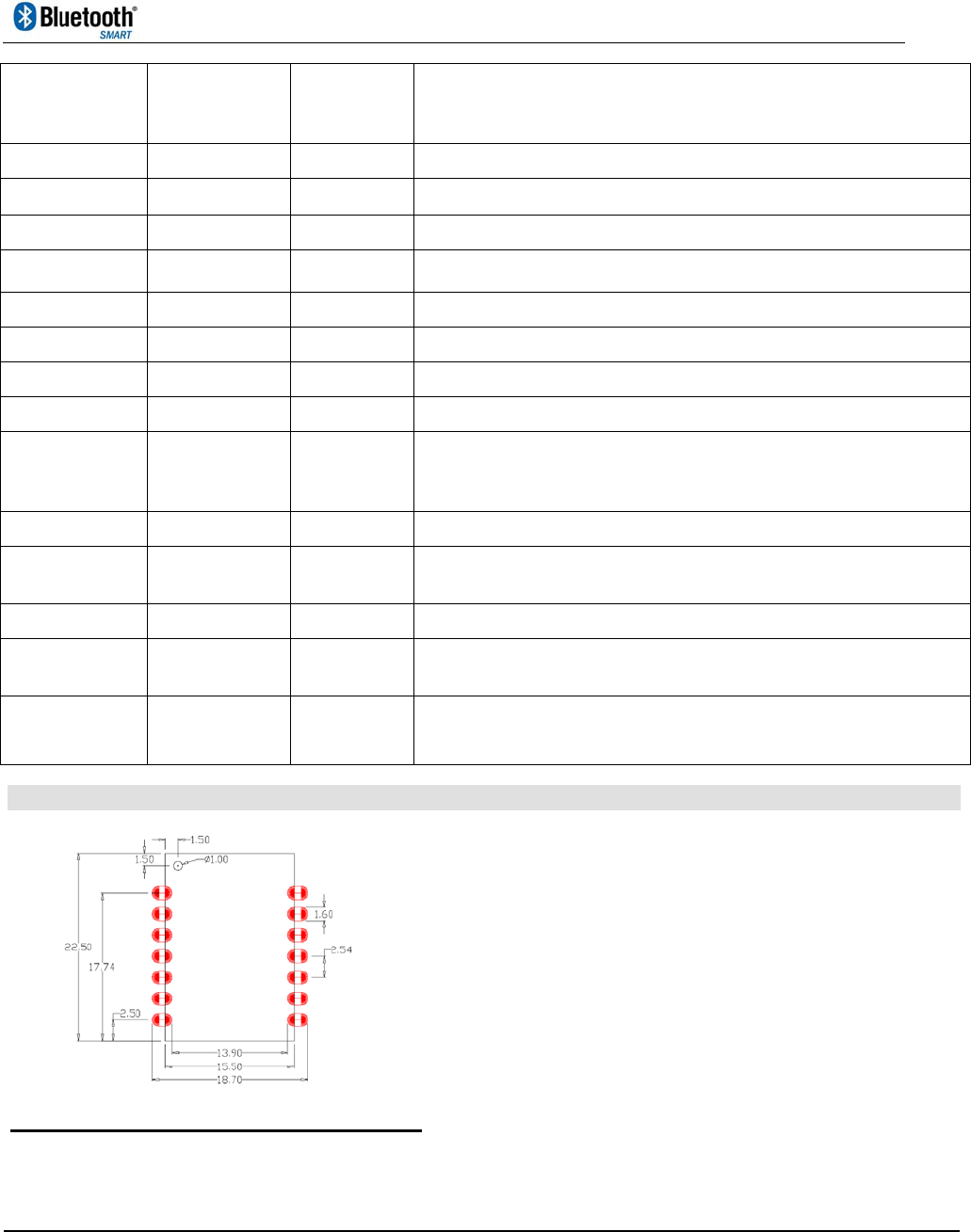
1.2 Pin Assignments and Dimensions
Top View Detailed Dimensions
All dimensions are in mm.
Connection pin pitch = 2.54 mm +/- 0.1mm
Module Thickness = 3.2mm max.
CMM-9301-SDT
Bluetooth Low Energy
Serial Data Bridge Module
SPEC No.
CMM-9301-SDT
BLE Bridge module
Revision
2.0
State
2015-03-04
C-MAX printed
2015-03-04
Version
English
Page
2 of 16
C-MAX
Pin Number Pin Name
Input to /
Output from
Module
Pin Description
1 RXD I RXD pin of UART communication with Host
2 Reserved I/O Reserved pin for future use
3 Reserved I/O Reserved pin for future use
4 Reserved I/O Reserved pin for future use
5 Reserved I/O Reserved pin for future use
6 GND GND Ground connection for module
7 TXD O TXD pin of UART communication with Host
8 UART_EN I Connect to VCC for UART serial data transfer mode
9 SLEEP I
Module wake up pin to wake module from low power sleep mode
(Wake-up = LO, Sleep = HI) . In Sleep mode UART interface will be
disabled.
10 VDD VDD 2.3 ~ 3.6 V voltage supply pin to module
11 IRQ O Interrupt Request Pin to signal host when data received in buffer and
ready to poll
12 RST I Reset (Active LO)
13 LINK O Module Link Indication signal (Bluetooth Disconnected = LO; Bluetooth
Connected = HI)
14 RESERVED I/O
Reserved pin for future use
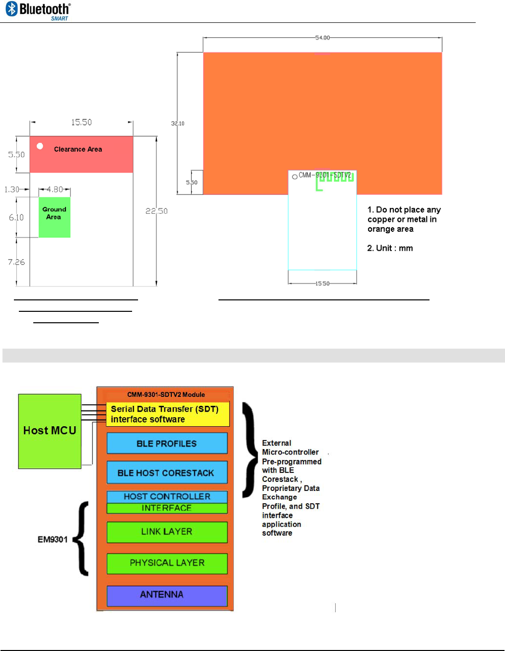
1.3 Recommended PCB layout and foot print
Recommended module contact pads footprint
CMM-9301-SDT
Bluetooth Low Energy
Serial Data Bridge Module
SPEC No.
CMM-9301-SDT
BLE Bridge module
Revision
2.0
State
2015-03-04
C-MAX printed
2015-03-04
Version
English
Page
3 of 16
C-MAX
Recommended Clearance Recommended Keepout area around Module
and Ground Plane Area
under Module
1.4 Module Block Diagram
CMM-9301-SDT
Bluetooth Low Energy
Serial Data Bridge Module
SPEC No.
CMM-9301-SDT
BLE Bridge module
Revision
2.0
State
2015-03-04
C-MAX printed
2015-03-04
Version
English
Page
4 of 16
C-MAX
1.5 Functional Modes
In general, the module has three functional modes of operation:
A. Sleep Mode: A HI state on the SLEEP pin will put the module into this mode, where the processor in
the module is in low power sleep mode. In this mode, the module cannot communicate with the Host
via UART communication. However, Bluetooth can be kept on and connected in this mode to listen for
any incoming data packets. The module will only be waken by a LO enable signal on the SLEEP pin .
B. On Mode: A LO state on the SLEEP pin will put the module into this mode. In this mode, the
processor in the module is awake and ready to communicate with the Host via UART communication.
UART communication is possible for all AT command operations. Once SLEEP pin is set back to HI,
the module will enter into Sleep Mode.
C. Test Mode: This mode is used for RF testing purposes only. By sending an AT command from
HOST to module (making sure that the SLEEP pin is set to LO first), the module will start RF Test
mode. By sending different test data to the SDT, the HOST can control the module to transmit on
different frequencies, in two different transmission modes : unmodulated carrier or modulated carrier
with test data pattern alternating 1s and 0s.
2. HOST Interface specification
2.1 Overview
UART interface is used for data transfer between host and SDT module.
The HOST system can send command/data or receive event information/data via UART interface.
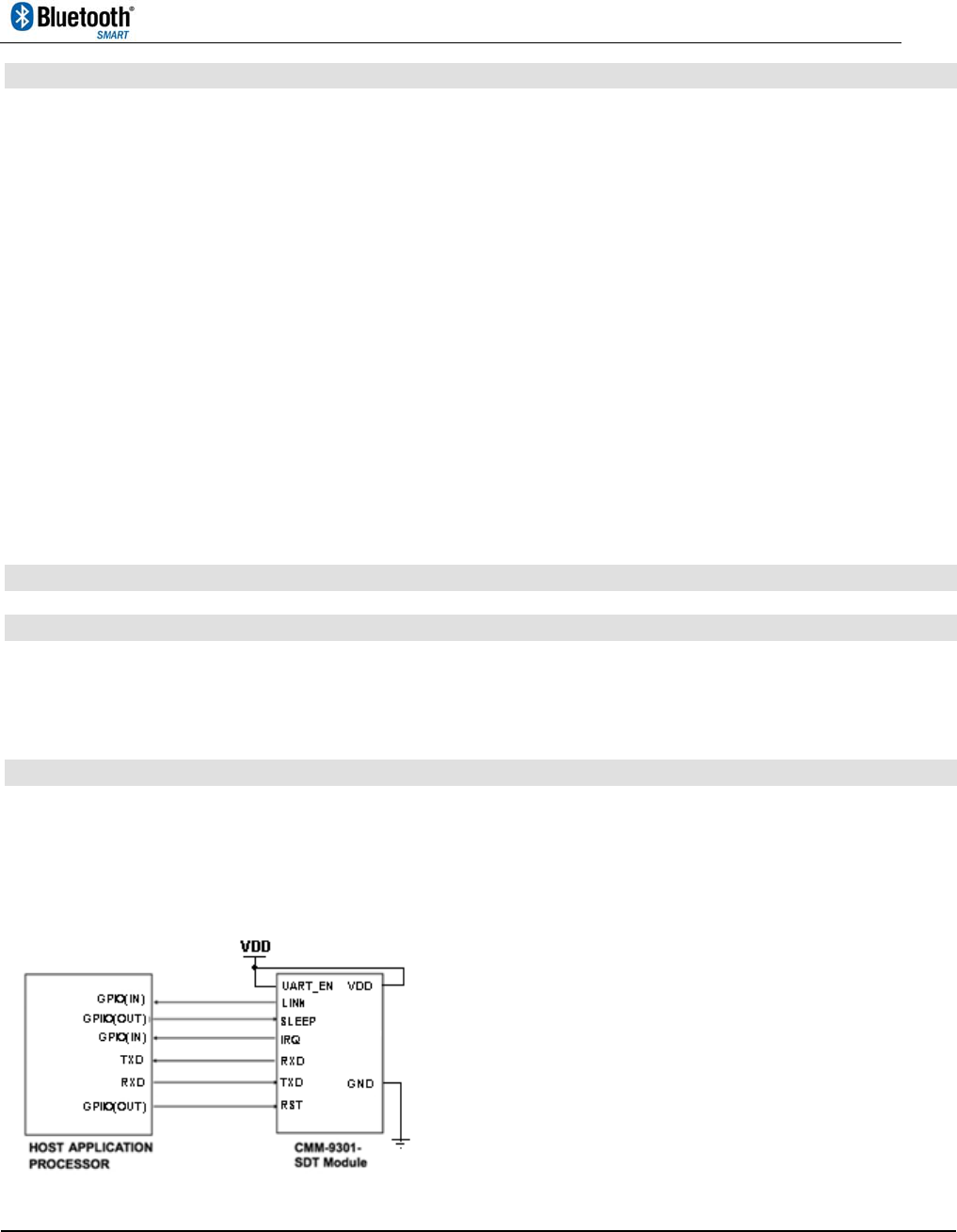
2.2 Connection with HOST systems
Connection with HOST system consist of the UART interface and 3 control pins.
The below is a reference diagram for the connection of the CMM-9301-SDTV2 module with an external
host processor:
The 3 control pins have the following functionality.
CMM-9301-SDT
Bluetooth Low Energy
Serial Data Bridge Module
SPEC No.
CMM-9301-SDT
BLE Bridge module
Revision
2.0
State
2015-03-04
C-MAX printed
2015-03-04
Version
English
Page
5 of 16
C-MAX
LINK: This pin indicates to HOST system the Bluetooth connectivity state of the SDT module. LINK
signal will be asserted to LOW at power up and in the event of Bluetooth disconnected. During
Bluetooth connected phase, LINK signal will be stay HIGH.
SLEEP: Control signal by HOST to wake module and start UART communication. It has to be asserted
Low before start serial communication. Asserting this pin back to High will put module into low power
sleep mode. Note that this pin does not control the Bluetooth connectivity. Bluetooth connectivity has to
be controlled via AT commands.
IRQ: IRQ indicates Bluetooth Data Received status from SDT module to HOST system. Regardless of
SLEEP pin status, when Bluetooth is turned on, once Bluetooth data is received, module will assert
IRQ signal to High . Hereafter, upon more received data packet (up to a maximum buffer of 64 packets
@ 20 bytes each), IRQ will be kept High until the received packet buffer is all cleared or if received
packets >= 64 packets, then IRQ will be asserted Low to indicate an empty buffer.
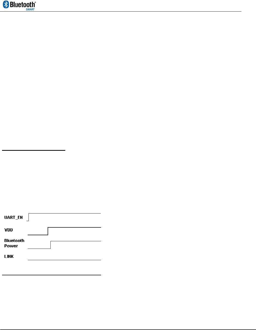
Behavior of each pins are described below.
Default status of LINK and IRQ signal is Low.
Host upon initialisation:
1. Set UART_EN = VDD
2. Power up module by applying power to VDD
3. Bluetooth is turned on automatically
4. If no data is expected to be transferred via Bluetooth, Bluetooth can be turned off by first asserting
SLEEP signal to Lo (to wake up module ready for UART communication), then issue AT Command :
AT+BTOFF.
5. To save power, keep SLEEP signal at High state when there is no UART communication.
For host to send data over Bluetooth:
1. HOST system assert SLEEP signal to Low (to wake up module ready for UART communication)
2. Issue AT command AT+BTON
3. Wait for peer device to connect to module. Once Bluetooth link with peer device is established, SDT
module asserts LINK signal to HIGH.
4. Send data by issuing AT Command AT+WRITEDATA = <Param>.
5. To disconnect Bluetooth, issue AT command : AT+BTDISCON, This will put module into
discoverable and connectable mode.

CMM-9301-SDT
Bluetooth Low Energy
Serial Data Bridge Module
SPEC No.
CMM-9301-SDT
BLE Bridge module
Revision
2.0
State
2015-03-04
C-MAX printed
2015-03-04
Version
English
Page
6 of 16
C-MAX
6. To turn off Bluetooth completely, issue AT command AT+BTOFF
7. HOST system asserts SLEEP signal to HIGH after finishing UART communication
For host to receive data from peer device via Bluetooth:
1. Assert SLEEP signal to Low (to wake up module ready for UART communication)
2. Issue AT command AT+BTON
3. Wait for peer device to connect to module. Once Bluetooth link with peer device is established, SDT
module asserts LINK signal to HIGH
4. When data is received via Bluetooth, SDT module asserts IRQ signal to HIGH
5. HOST system detects IRQ
6. Issue AT command AT+READDATA? to read received data stored in buffer
7. To keep module in connected mode, just put module into low power mode by asserting SLEEP
signal to HIGH
8. To disconnect from Bluetooth but to remain discoverable and connectable, issue AT command :
AT+BTDISCON, then put module into low power mode by asserting SLEEP signal to HIGH
9. To turn off Bluetooth completely, issue AT command AT+BTOFF
10. Assert SLEEP signal to HIGH after finishing UART communication
CMM-9301-SDT
Bluetooth Low Energy
Serial Data Bridge Module
SPEC No.
CMM-9301-SDT
BLE Bridge module
Revision
2.0
State
2015-03-04
C-MAX printed
2015-03-04
Version
English
Page
7 of 16
C-MAX
2.3 UART physical interface specification
UART bridge interface between CMM-9301-SDT module and the host controller is enable by setting
the pin UART_EN to HIGH. Under UART mode, command transaction from host to module must be in
AT command format.
UART Settings:
ParameterConfigurationDefault
BaudRate300‐115200bpssettableoverUART
1200bps
(noteearlysampleshavedefaultof
115200bps)
Datasize8bits
ParitybitNoParity
Stopbit1stopbit
FlowcontrolNotsupported
3 AT Command List
OperationsDescriptionsATCommands
(UARTmode)
Operational
ResetResetbothMCUandEM9301AT+RESET
TestTestmodestart/exitAT+TEST=<Param>
BT_OnTurnonBluetoothinadvertisingmodeAT+BTON
BT_DisConDisconnectBluetooth,EM9301inadvertisingmodeAT+BTDISCON
BT_OffTurnoffBluetoothandpowerdownEM9301AT+BTOFF
Read_EERestoreSettingsfromeepromAT+READE2?
Write_EESaveSettingsintoeepromAT+WRITEE2
Read_Data
ReadOldestReceivedDataviaBluetoothstoredin
bufferAT+READDATA?
Write_DataWriteDatatoSDTmoduletobesentviaBluetoothAT+WRITEDATA=<Param>
Read_Packets
Readnumberofpacketsinbufferunread(20bytes
perpacket)AT+PACKETS?
SettingConfigurations
Set_NameSetBLEDeviceNameAT+NAME=<Param>
Set_UART_BaudRateSetcommunicationbaudrateofUARTinterfaceAT+BAUDRATE=<Param>

CMM-9301-SDT
Bluetooth Low Energy
Serial Data Bridge Module
SPEC No.
CMM-9301-SDT
BLE Bridge module
Revision
2.0
State
2015-03-04
C-MAX printed
2015-03-04
Version
English
Page
8 of 16
C-MAX
Set_ModelNum
SetLocalDeviceModelNumberinDevice
InformationServiceAT+MODEL=<Param>
Set_SerialNum
SetLocalDeviceSerialNumberinDevice
InformationServiceAT+SERIAL=<Param>
Set_HardVer
SetLocalDeviceHardwareVersionNumberin
DeviceInformationServiceAT+HWVER=<Param>
Set_SoftVer
SetLocalDeviceSoftwareVersionNumberinDevice
InformationServiceAT+VERSION=<Param>
Set_Manufacturer
SetLocalDeviceManufacturerNameinDevice
InformationServiceAT+OEM=<Param>
Set_ConnInt
SetConnectionIntervalrelatedparameters.(Note
thatsettingoftheseparametersmustbeinline
withtheconditionssetbyBluetoothSIGandApple)
AT+CONN=<SET><SPACE><M
inConnInt><SPACE><MaxCon
nInt><SPACE><ConnLatency>
<SPACE><ConnTimeout>
Set_AdvDataSetManufacturerSpecificAdvertisingDataAT+ADVDATA=<Param>
PairEnablePairingwhenconnectingviaBluetoothAT+PAIR=<Param>
Set_PowerSetBluetoothtransmissionoutputpowerAT+POWER=<Param>
ReadingConfigurations
Read_NameReadBLEDeviceNameAT+NAME?
Read_AddrReadLocalDeviceAddressAT+ADDR?
Read_DeviceInfo
ReadLocalDeviceInformationincluding–
ModelNum,SerialNum,HardVer,SoftVer,
ManufacturerAT+DEVICEINFO?
Read_ConnIntReadConnectionIntervalAT+CONN?
Read_AdvDataReaddatatoadvertiseAT+ADVDATA?
Read_PowerReadsetBluetoothtransmissionoutputpowerAT+POWER?
Important Note:
All changes performed in setting configurations are saved into RAM, in order for changes to
take effect and preserved, changes should be saved into eeprom via the command Write_EE,
then re-power on or reset the module.
For detailed AT command list and examples, please refer to documentation CMM-9301-SDT-
supp_20141215.pdf
CMM-9301-SDT
Bluetooth Low Energy
Serial Data Bridge Module
SPEC No.
CMM-9301-SDT
BLE Bridge module
Revision
2.0
State
2015-03-04
C-MAX printed
2015-03-04
Version
English
Page
9 of 16
C-MAX
4. Default Settings
ParameterSystemDefaultsuponpoweron
UARTBaudrate1200bps
BluetoothStatusBluetoothturnedonasperipheralinadvertisingbroadcastmode
BLEDeviceNameC‐MAX
LocalDeviceAddressUniqueforeachmodule,startingwithC‐MAXidentifier90:2C:C7
LocalDeviceInformation
ModelNum:CMM9301‐SDT
SerialNum:2ABBXCM9301SDT
HardwareVersion:V2
SoftwareVersion:R2.00
Manufacturer:C‐MAXAsiaLtd
Connectioninterval125ms
Advertisinginterval125ms
OutputPower0dBm
PairingOptionPairingandBondingEnabled
ManufacturerSpecific
AdvertisingData00000000000000000000000000
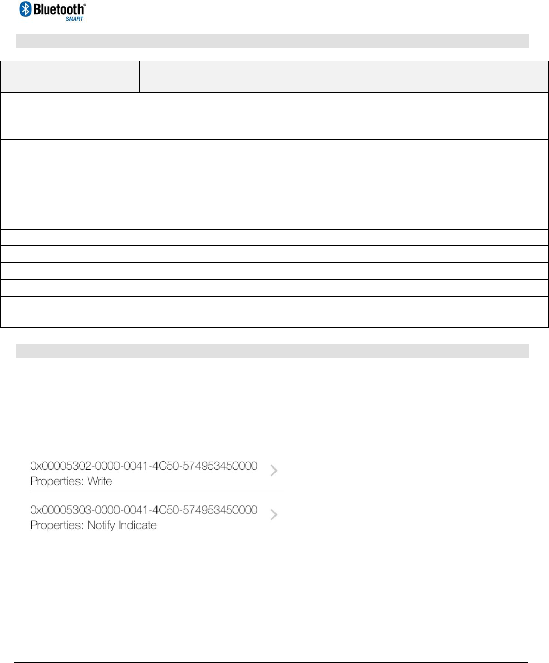
5.1 Mobile APP Data Exchange Service
In order to allow your APP to receive data from and transmit data to the CMM-9301-SDT module, your
APP will have to link up to our proprietary data exchange profile with the following service UUID:
0x00005301-0000-0041-4C50-574953450000
And the following characteristics UUID:
The 5302 characteristic allows the mobile APP to write data (maximum 20 bytes per transmission) to
the module and the 5303 characteristic allows the mobile APP to receive data as both notification or
indication data from the module.
CMM-9301-SDT
Bluetooth Low Energy
Serial Data Bridge Module
SPEC No.
CMM-9301-SDT
BLE Bridge module
Revision
2.0
State
2015-03-04
C-MAX printed
2015-03-04
Version
English
Page
10 of 16
C-MAX
5.2 Mobile APP Device Information Service
Device Information of the module can be acquired by an APP via discovering the standard Bluetooth
SIG service: Device Information Service. This service has the UUID of 0x180A, and has the module
has the following characteristics (with their respective UUID on the right) available:
// DEVICE INFORMATION Service Model number UUID
#define BLEUUID_DEVICEINFORMATION_MODEL_NUMBER 0x2A24
// DEVICE INFORMATION Service Serial Number UUID
#define BLEUUID_DEVICEINFORMATION_SERIAL_NUMBER 0x2A25
// DEVICE INFORMATION Service Hardware Revision UUID
#define BLEUUID_DEVICEINFORMATION_HARDWARE_REVISION 0x2A27
// DEVICE INFORMATION Service Software Revision UUID
#define BLEUUID_DEVICEINFORMATION_SOFTWARE_REVISION 0x2A28
// DEVICE INFORMATION Service manufacturer name UUID
#define BLEUUID_DEVICEINFORMATION_MANUFACTURER_NAME 0x2A29
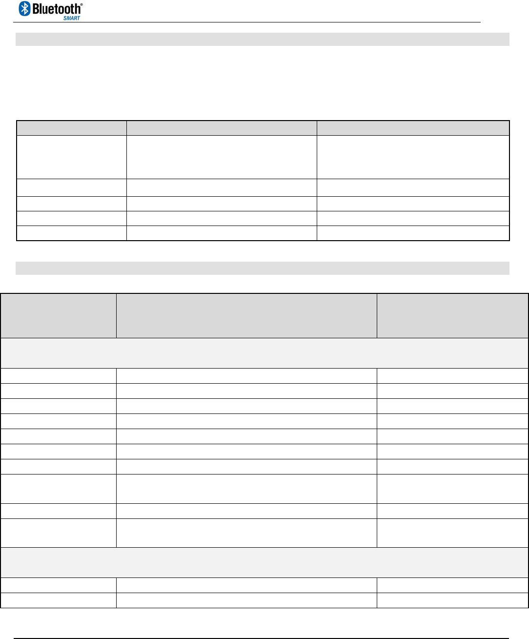
6. Module Electrical Specifications
Specification CMM-9301-SDTV2
Storage Temperature Range - 40 to + 85 degrees C
Operating Temperature Range - 20 to + 60 degrees C
Voltage Range 2.3V to 3.6V
Frequency Range 2.400 to 2.484 GHz
Modulation GFSK
On-air data rate 1Mbps
RF channels 40
Average Current Consumption,
Conditions: Bluetooth Broadcast Interval and Connection interval on default 30 ms,
Vcc = 3.0, output power = 0 dBm
SLEEP pin status Bluetooth Status Bluetooth Connection Typical Average Current
(mA)
LO OFF DISCONNECTED 2.34
HI ON CONNECTED 0.39
HI ON DISCONNECTED 0.39
HI OFF DISCONNECTED 0.007

CMM-9301-SDT
Bluetooth Low Energy
Serial Data Bridge Module
SPEC No.
CMM-9301-SDT
BLE Bridge module
Revision
2.0
State
2015-03-04
C-MAX printed
2015-03-04
Version
English
Page
11 of 16
C-MAX
7. FCC Statement
NOTICE: This device complies with Part 15 of the FCC Rules. Operation is subject to the following two
conditions:
This device may not cause harmful interference, and
This device must accept any interference received, including interference that may cause
undesired operation.
The Grantee is not responsible for any changes or modifications not expressly approved by the party
responsible for compliance. Such modifications could void the user’s authority to operate the
equipment.
This equipment has been tested and found to comply with the limits for a Class B digital device,
pursuant to Part 15 of the FCC Rules. These limits are designed to provide reasonable protection
against harmful interference in a residential installation. This equipment generates, uses and can
radiate radio frequency energy and if not installed and used in accordance with the instructions, may
cause harmful interference to radio communications. However, there is no guarantee that interference
will not occur in a particular installation. If this equipment does cause harmful interference to radio or
television reception, which can be determined by turning the equipment off and on, the user is
encouraged to try to correct the interference by one or more of the following measures:
Reorient or relocate the receiving antenna.
Increase the separation between the equipment and receiver
Connect the equipment into an outlet on a circuit different from that to which the receiver is
connected.
Consult the dealer or an experienced radio/TV technician for help
Radio frequency radiation exposure information:
This equipment complies with FCC radiation exposure limits set forth for an uncontrolled environment.
Please see the RF Exposure information. This transmitter must not be co-located or operating in
conjunction with any other antenna or transmitter.
This device should be installed and operated with a minimum distance of 20cm between the antenna
and all persons.
Label requirements:
Contains: FCC ID: 2ABBXCM9301SDT2014
FCC RF Exposure Requirement:
At least 20cm separation distance between the antenna and the user’s body must be maintained at
all times. And must not transmit simultaneously with any other antenna or transmitter, except in
accordance with FCC multi transmitter product procedures.
To comply with FCC regulations limiting both maximum RF output power and human exposure to
RF radiation, the maximum antenna gain including cable loss in a mobile-only exposure condition
must not exceed 0dBi in the 2.4GHz band.

CMM-9301-SDT
Bluetooth Low Energy
Serial Data Bridge Module
SPEC No.
CMM-9301-SDT
BLE Bridge module
Revision
2.0
State
2015-03-04
C-MAX printed
2015-03-04
Version
English
Page
12 of 16
C-MAX
A user manual with the end product must clearly indicate the operating requirements and conditions
that must be observed to ensure compliance with current FCC RF exposure guidelines.
Note: If this module is intended for use in a portable device, you are responsible for separate approval
to satisfy the SAR requirements of FCC Part 2.1093.
Please be noted that the following information and instructions should be placed in the end-
user’s operating manual.
The CMM-9301-SDT Module must be installed in the designated host as specified in this manual.
Separate approval is required for all other operating configurations, including portable
configurations with respect to 2.1093 and different antenna configurations.
The CMM-9301-SDT Module and its antenna must not be co-located or operating in conjunction
with any other transmitter or antenna within a host device. This equipment complies with FCC RF
radiation exposure limits set forth for an uncontrolled environment.
A label must be affixed to the outside of the end product into which the CMM-9301-SDT Module is
incorporated, with a statement similar to the following: For CMM-9301-SDT: This device contains
FCC ID: 2ABBXCM9301SDT2014.
The module shall be in non-detachable construction protection into the finished products, so that
the end-user has to destroy the module while remove or install it.
This module is to be installed only in mobile or fixed applications. According to FCC part 2.1091(b)
definition of mobile and fixed devices is:
Mobile Device:
A mobile device is defined as a transmitting device designed to be used in other than fixed
locations and to generally be used in such a way that a separation distance of at least 20
centimeters is normally maintained between the transmitter’s radiating structure(s) and the body of
the user or nearby persons. In this context, the term ‘‘fixed location’’ means that the device is
physically secured at one location and is not able to be easily moved to another location.
Portable Device:
For purposes of this section, a portable device is defined as a transmitting device designed to be
used so that the radiating structure(s) of the device is/are within 20 centimeters of the body of the
user.
Separate approval is required for all other operating configurations, including portable
configurations with respect to FCC Part 2.1093 and different antenna configurations.
A certified modular has the option to use a permanently affixed label, or an electronic label. For a
permanently affixed label, the module must be labeled with an FCC ID: 2ABBXCM9301SDT2014.
The OEM manual must provide clear instructions explaining to the OEM the labeling requirements,
options and OEM user manual instructions that are required.
For a host using this FCC certified modular with a standard fixed label, if (1) the module’s FCC ID is
not visible when installed in the host, or (2) if the host is marketed so that end users do not have
straightforward commonly used methods for access to remove the module so that the FCC ID of
the module is visible; then an additional permanent label referring to the enclosed module:
“Contains: FCC ID : 2ABBXCM9301SDT2014” must be used. The host OEM user manual must

CMM-9301-SDT
Bluetooth Low Energy
Serial Data Bridge Module
SPEC No.
CMM-9301-SDT
BLE Bridge module
Revision
2.0
State
2015-03-04
C-MAX printed
2015-03-04
Version
English
Page
13 of 16
C-MAX
also contain clear instructions on how end users can find and/or access the module and the FCC ID.
Host product is required to comply with all applicable FCC equipment authorizations regulations,
requirements and equipment functions not associated with the transmitter module portion,
compliance must be demonstrated to regulations for other transmitter components within the host
product; to requirements for unintentional radiators (Part 15B). To ensure compliance with all non-
transmitter functions the host manufacturer is responsible for ensuring compliance with the
module(s) installed and fully operational. If a host was previously authorized as an unintentional
radiator under the Declaration of Conformity procedure without a transmitter certified module and
a module is added, the host manufacturer is responsible for ensuring that after the module is
installed and operational the host continues to be compliant with the Part 15B unintentional
radiator requirements. Since this may depend on the details of how the module is integrated with
the host, the grantee (the party responsible for the module grant) shall provide guidance to the
host manufacturer for compliance with the Part 15B requirements.
OEM RESPONSIBILITIES TO COMPLY WITH FCC REGULATIONS
The CMM-9301-SDT Module has been certified for integration into products only by OEM integrators
under the following conditions: This device is granted for use in Mobile only configurations in which the
antennas used for this transmitter must be installed to provide a separation distance of at least 20
centimeters from all persons and not be co-located with any other transmitters except in accordance
with FCC and Industry Canada multi-transmitter product procedures.
As long as the two conditions above are met, further transmitter testing will not be required. However,
the OEM integrator is still responsible for testing their end-product for any additional compliance
requirements required with this module installed (for example, digital device emissions, PC peripheral
requirements, etc.).
IMPORTANT NOTE:
In the event that these conditions cannot be met (for certain configurations or co-location with
another transmitter), then the FCC and Industry Canada authorizations are no longer
considered valid and the FCC ID and IC Certification Number cannot be used on the final
product. In these circumstances, the OEM integrator will be responsible for re-evaluating the
end product (including the transmitter) and obtaining a separate FCC and Industry Canada
authorization.
OEM LABELING REQUIREMENTS FOR END-PRODUCT
The CMM-9301-SDT module is labeled with its own FCC ID Certification Number. The FCC ID
certification numbers are not visible when the module is installed inside another device, as such the
end device into which the module is installed must display a label referring to the enclosed module. The
final end product must be labeled in a visible area with the following: “Contains: FCC ID:
2ABBXCM9301SDT2014”.
The OEM of the CMM-9301-SDT Module must only use the approved antenna(s) listed above, which
have been certified with this module. The device carries FCC authorization and is marked with the FCC
ID Number. Whilst any device into which this authorized module is installed will not normally be
required to obtain FCC authorization, this does not preclude the possibility that some other form of

CMM-9301-SDT
Bluetooth Low Energy
Serial Data Bridge Module
SPEC No.
CMM-9301-SDT
BLE Bridge module
Revision
2.0
State
2015-03-04
C-MAX printed
2015-03-04
Version
English
Page
14 of 16
C-MAX
authorization or testing may be required for the finished device.
OEM END PRODUCT USER MANUAL STATEMENTS
The OEM integrator should not provide information to the end user regarding how to install or remove
this RF module or change RF related parameters in the user manual of the end product.
If this module is intended for use in a portable device, you are responsible for separate approval to
satisfy the SAR requirements of FCC Part 2.1093.
The user manual for the end product must include the following information in a prominent
location:
This device is granted for use in mobile only configurations in which the antennas used for this
transmitter must be installed to provide a separation distance of at least 20 centimeters from all
persons and not be co-located with any other transmitters except in accordance with FCC and Industry
Canada multi-transmitter product procedures.
The end product with an embedded FCC ID: 2ABBXCM9301SDT2014 Module may also need to pass
the FCC Part 15 unintentional emission testing requirements and be properly authorized per FCC Part
15.
The labeling instructions of finished products refer to following requirements:
A certified module has the option to use a permanently affixed label, or an electronic label (see
Electronic Labeling below). For a permanently affixed label, the module must be labeled with an FCC
ID - Section 2.926 (see Certification labeling requirements above). The OEM manual must provide
clear instructions explaining to the OEM the labeling requirements, options and OEM user manual
instructions that are required (see next paragraph).
For a host using a certified module with a standard fixed label, if (1) the module’s FCC ID is not visible
when installed in the host, or (2) if the host is marketed so that end users do not have straight forward
commonly used methods for access to remove the module so that the FCC ID of the module is visible;
then an additional permanent label referring to the enclosed module: “Contains FCC ID:
2ABBXCM9301SDT2014” must be used. The host OEM user manual must also contain clear
instructions on how end users can find and/or access the module and the FCC ID.
Other user manual statements may apply.
8. R&TTE Statement
Hereby, C-MAX Asia Limited declares that this CMM-9301-SDT module is in compliance with the
essential requirements and other relevant provisions of Directive 1999/5/EC.
CMM-9301-SDT
Bluetooth Low Energy
Serial Data Bridge Module
SPEC No.
CMM-9301-SDT
BLE Bridge module
Revision
2.0
State
2015-03-04
C-MAX printed
2015-03-04
Version
English
Page
15 of 16
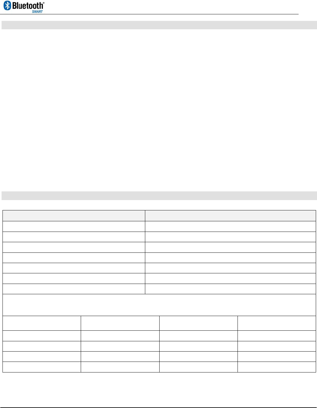
C-MAX
9. Temperature Profile for Lead-free Reflow Soldering
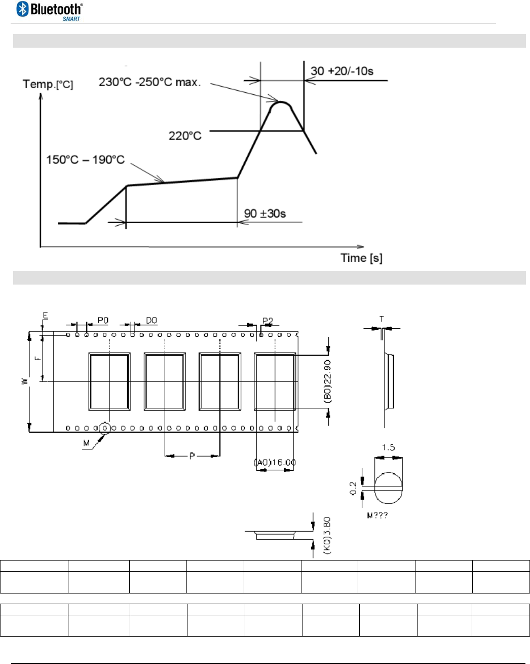
10. Packaging Information
Tape & Reel: 1Kpcs/reel
Item D0 D
1 P
0 P
2 E W A
0 A
1
Dimension 1.50
+0.10-0.00
0.00
+0.00-0.00
4.00
+0.10-0.10
2.00
+0.10-0.10
1.75
+0.10-0.10
44.0
+0.30-0.30
16.0
+0.10-0.10
0.00
+0.10-0.10
Item B0 B
1 K
0 K
1 P F T
Dimension 22.9
+0.10-0.10
0.00
+0.00-0.00
3.80
+0.10-0.10
0.00
+0.10-0.10
24.0
+0.10-0.10
20.2
+0.10-0.10
0.35
+0.05-0.05

CMM-9301-SDT
Bluetooth Low Energy
Serial Data Bridge Module
SPEC No.
CMM-9301-SDT
BLE Bridge module
Revision
2.0
State
2015-03-04
C-MAX printed
2015-03-04
Version
English
Page
16 of 16
C-MAX
11. Ordering Information
Disclaimer of Warranty
Information furnished is believed to be accurate and reliable. However C-MAX assumes no responsibility, neither for the consequences of use
of such information nor for any infringement of patents or other rights of third parties, which may result from its use. Specifications mentioned
in this publication are subject to change without notice. This publication supersedes and replaces all information previously supplied. C-MAX
products are not authorized for use as critical components in life support devices without express written approval of C-MAX.
Note
It is not given warranty that the declared circuits, devices, facilities, components, assembly groups or treatments included herein are free from
legal claims of third parties. The declared data are serving only to description of product. They are not guaranteed properties as defined by
law. The examples are given without obligation and cannot give rise to any liability.
Reprinting this data sheet - or parts of it - is only allowed with a license of the publisher.
C-MAX reserves the right to make changes on this specification without notice at any time.
C-MAX Asia Ltd C-MAX Technology Ltd (Shenzhen)
Unit 117, 1/F., Room 922-923, 9/F.,
Liven House, Kerry Centre,
61-63 King Yip Street, 2008 Reminnan Road,
Kwun Tong, Kowloon, HK SAR Luohu District, Shenzhen, PR China,
Tel.: +852-2798-5182 Tel:+86-755-25181858
Fax: +852-2798-5379 Fax:+86-755-25181859
e-mail: enquiry@c-max.com.hk
C-MAX Module
Part Number Delivery Form Size
(mm)
Typical Operating
Voltage (V)
CMM-9301-SDTV2-DEX
Shielded,
no pin connectors,
Tape and Reel
22.5 x 15.5 2.3 ~ 3.6