CAEN RFID srl CAENRFID002 Low Power Communication Device Transmitter User Manual RFIDdemo rev1
CAEN RFID srl Low Power Communication Device Transmitter RFIDdemo rev1
Contents
- 1. Users Manual I
- 2. Users Manual II
- 3. Users Manual III
- 4. Users Manual IV
Users Manual IV

Technical
Information
Manual
18 February 2006
Revision n. 1
RFID SOFTWARE
USER INTERFACE
NPO:
00117/03:Demox.MUTx/01

Document type: Title: Revision date: Revision:
User's Manual (MUT) RFID Software User Interface 18/02/2006 1
INDEX
1. OVERVIEW ................................................................................................................................................5
2. GETTING STARTED ................................................................................................................................6
2.1. SOFTWARE USER INTERFACE: INSTALLATION.........................................................................................6
2.2. LAUNCHING THE SOFTWARE USER INTERFACE.......................................................................................7
2.3. CONNECTION CONFIGURATION...............................................................................................................8
2.3.1. Reader protocol configuration ......................................................................................................8
2.3.2. Network configuration...................................................................................................................8
2.3.3. Input output management..............................................................................................................9
2.4. LOGICAL SOURCE SELECTION .................................................................................................................9
2.5. DETECTING TEST TAGS WITH THE RF FIELD..........................................................................................10
2.6. READOUT OF ONE TAG’S MEMORY........................................................................................................12
2.6.1. EPC protocol tags operations .....................................................................................................13
2.7. TEMPERATURE MONITORING WITH THE SEMIPASSIVE TAG....................................................................14
2.8. CREATING THE LOG FILE ......................................................................................................................15
2.9. RF FIELD TEST .....................................................................................................................................15
2.10. QUIT CAEN RFID DEMO PROGRAM................................................................................................15
2.11. ISO18000-6B PROTOCOL TAGS OPERATIONS ...................................................................................15
2.12. EPC1.19 PROTOCOL TAGS OPERATIONS ...........................................................................................17
2.12.1. EPC 1.19 Tag Data memory mapping (96 bit)............................................................................17
2.12.2. EPC 1.19 Tag Data memory mapping (64 bit)............................................................................18
3. FIRMWARE UPGRADE.........................................................................................................................19
3.1. FIRMWARE UPGRADE VIA SERIAL PORT ................................................................................................19
3.2. FIRMWARE UPGRADE VIA TCP/IP.........................................................................................................20
4. RFID TEST PROGRAM..........................................................................................................................22
4.1. CONNECTION CONFIGURATION.............................................................................................................22
4.2. SETTINGS .............................................................................................................................................23
4.2.1. Antenna selection.........................................................................................................................23
4.2.2. Protocol selection........................................................................................................................23
4.2.3. Power settings .............................................................................................................................24
4.2.4. Reader network configuration.....................................................................................................24
4.3. START TEST..........................................................................................................................................24
4.4. QUIT CAEN RFID TEST PROGRAM......................................................................................................25
NPO: Filename: Number of pages: Page:
00117/03:Demox.MUTx/01 RFIDDEMO_REV1.DOC 27 2

Document type: Title: Revision date: Revision:
User's Manual (MUT) RFID Software User Interface 18/02/2006 1
5. RFID CSDEMO PROGRAM...................................................................................................................26
5.1. CONNECTION CONFIGURATION.............................................................................................................26
5.2. START INVENTORY ...............................................................................................................................27
5.3. READ TAGS MEMORY............................................................................................................................27
LIST OF FIGURES
FIG. 2.1 – CAEN RFID CD MAIN MENU......................................................................................................6
FIG. 2.2 – CAEN RFID DEMO START WINDOW.............................................................................................7
FIG. 2.3 – CONNECTION PORT CONFIGURATION .............................................................................................8
FIG. 2.4 – READER NETWORK CONFIGURATION.............................................................................................8
FIG. 2.5 – READER NETWORK CONFIGURATION.............................................................................................9
FIG. 2.6 – LOGICAL SOURCE SELECTION AND TEST.........................................................................................9
FIG. 2.7 – EVENT MODE CONFIGURATION ....................................................................................................10
FIG. 2.8 – CHANGE EVENT MODE MESSAGE .................................................................................................11
FIG. 2.9 – ASYNCHRONOUS ACQUISITION CONFIGURATION.........................................................................11
FIG. 2.10 – RFID SERVER............................................................................................................................11
FIG. 2.11 – TAGS MEMORY...........................................................................................................................12
FIG. 2.12 – TAG READOUT ...........................................................................................................................13
FIG. 2.13 – TAG PROGRAMMING ..................................................................................................................13
FIG. 2.14 – TAG KILLING..............................................................................................................................14
FIG. 2.15 – TEMPERATURE MONITORING/1 ..................................................................................................14
FIG. 2.16 – TEMPERATURE MONITORING/2 ..................................................................................................15
FIG. 2.17 – ISO18000-6B TAGS MEMORY...................................................................................................16
FIG. 2.18 – ISO18000-6B TAG READOUT....................................................................................................16
FIG. 2.19 – EPC1.19 TAG PROGRAMMING ...................................................................................................17
FIG. 2.20 – EPC1.19 TAG LOCKING.............................................................................................................17
FIG. 2.21 – GENERAL STRUCTURE OF 96 BIT EPC NUMBER .........................................................................17
FIG. 2.22 – SEPARATION OF 96 BIT DATA STRUCTURE FOR UCODE EPC 1.19............................................18
FIG. 2.23 – MAPPING OF 96 BIT DATA STRUCTURE INTO UCODE EPC 1.19 MEMORY ................................18
FIG. 2.24 – GENERAL STRUCTURE OF 64 BIT EPC NUMBER .........................................................................18
FIG. 2.25 – SEPARATION OF 64 BIT DATA STRUCTURE FOR UCODE EPC 1.19............................................18
FIG. 2.26 – MAPPING OF 64 BIT DATA STRUCTURE INTO UCODE EPC 1.19 MEMORY ................................18
FIG. 3.1 – CAEN RFID DEMO DIRECTORIES.............................................................................................19
FIG. 3.2 – CAEN RFIDUPGRADE/1.............................................................................................................19
FIG. 3.3 – SELECTING THE IMAGE FILE.........................................................................................................19
FIG. 3.4 – PUMPKIN MENU WINDOW..........................................................................................................20
FIG. 3.5 – PUMPKIN OPTIONS WINDOW......................................................................................................20
NPO: Filename: Number of pages: Page:
00117/03:Demox.MUTx/01 RFIDDEMO_REV1.DOC 27 3

Document type: Title: Revision date: Revision:
User's Manual (MUT) RFID Software User Interface 18/02/2006 1
FIG. 3.6 – FIRMWARE UPGRADE BROWSER...................................................................................................21
FIG. 3.7 – FIRMWAREUPGRADE MESSAGE ....................................................................................................21
FIG. 3.8 – CONFIRMATION MESSAGE............................................................................................................21
FIG. 4.1 – RFID TEST MAIN MENU...............................................................................................................22
FIG. 4.2 – CONNECTION PORT CONFIGURATION ...........................................................................................22
FIG. 4.3 – SOURCE SELECTION .....................................................................................................................23
FIG. 4.4 – SETTING THE PROTOCOL ..............................................................................................................23
FIG. 4.5 – POWER SETTINGS FIELDS .............................................................................................................24
FIG. 4.6 – NETWORK CONFIGURATION.........................................................................................................24
FIG. 4.7 – TAGS DETECTION.........................................................................................................................24
FIG. 5.1 – RFID TEST MAIN MENU...............................................................................................................26
FIG. 5.2 – CONNECTION CONFIRMATION ......................................................................................................26
FIG. 5.3 – TAGS DETECTION.........................................................................................................................27
FIG. 5.4 – TAGS MEMORY READOUT.............................................................................................................27
LIST OF TABLES
TABLE 2.1 – CAEN RFID DEMO DIRECTORIES ...........................................................................................7
NPO: Filename: Number of pages: Page:
00117/03:Demox.MUTx/01 RFIDDEMO_REV1.DOC 27 4

Document type: Title: Revision date: Revision:
User's Manual (MUT) RFID Software User Interface 18/02/2006 1
1. Overview
The present manual describes how to operate with the software pack provided with
CAEN RFID UHF readers and development kits.
The CD includes the following tools:
− RFID Java Demo program
− RFID Visual C++ test program
− RFID .Net Sample
− Upgrade firmware and protocols (for A928EU/A948EU, A828EU/A829EU,
A828US/A829US, A949EU/A946EU)
− Uninstall tool
NPO: Filename: Number of pages: Page:
00117/03:Demox.MUTx/01 RFIDDEMO_REV1.DOC 27 5
Document type: Title: Revision date: Revision:
User's Manual (MUT) RFID Software User Interface 18/02/2006 1
2. Getting started
2.1. Software User interface: installation
Before you begin, be sure that:
1. the Reader is not connected to your computer;
2. the Reader supports your operating system (Windows 2000/XP);
To install the software:
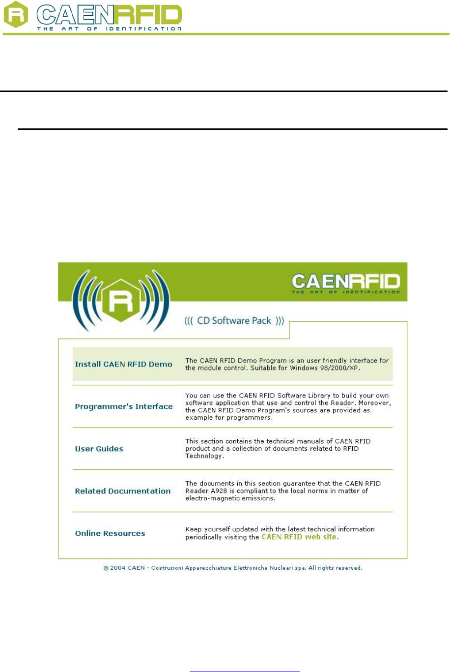
Place the CD in the CD tray in your PC.
Then the following menu will open:
Fig. 2.1 – CAEN RFID CD Main Menu
If the menu does not open, then Double-click on “My Computer”.
Double-click on the CD-ROM drive.
Double click on “index.html”.
Double-click on the file name “Install CAEN RFID Demo” option.
NPO: Filename: Number of pages: Page:
00117/03:Demox.MUTx/01 RFIDDEMO_REV1.DOC 27 6
Document type: Title: Revision date: Revision:
User's Manual (MUT) RFID Software User Interface 18/02/2006 1
Setup will install the files in the folder listed under “Destination Folder”. To install to this
folder, click “Next”. To install to a different folder, click “Browse” and select another
folder.
The Setup program creates the following directories:
Table 2.1 – CAEN RFID DEMO directories
Directory/file name Directory files description
Java RFID Demo Java Version (see § 2)
CAENRFIDlib.dll1Include files
lib CAENRFIDlib.lib (stub for Microsoft Visual C++ 6.0)
sources demo program Microsoft Visual C++ 6.0 Source files
RFID_Demo.exe demo program
RFIDUpgrade.exe Upgrade firmware and protocols
TestRFID.exe RFID Test program
Unins000 Uninstall tool
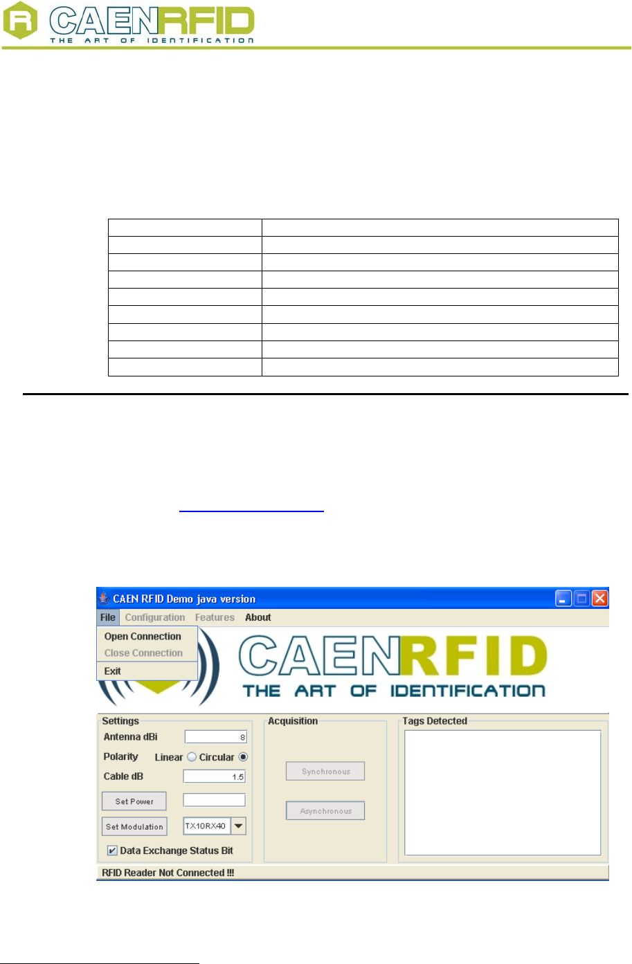
2.2. Launching the Software User interface
The RFID Demo Java Version is started by launching the CAENRFIDJavaDemo.jar file in
the CAEN_RFID_Development_kit_Java\CAENRFIDJavaDemo folder in the CD’s
“Programmer's Interface” directory.
The present program is developed for demonstrative purposes, the Java classes are
available in the “Programmer's Interface” directory of the CD.
Before launching the RFID Demo Java Version, it is necessary to install the Java 2
Platform Standard Edition 5.0, available at: http://java.sun.com/j2se/1.5.0/download.jsp
Fig. 2.2 – CAEN RFID Demo start window
1 CAENRFIDLib library is described in the relevant Technical Information Manual
NPO: Filename: Number of pages: Page:
00117/03:Demox.MUTx/01 RFIDDEMO_REV1.DOC 27 7
Document type: Title: Revision date: Revision:
User's Manual (MUT) RFID Software User Interface 18/02/2006 1
2.3. Connection configuration
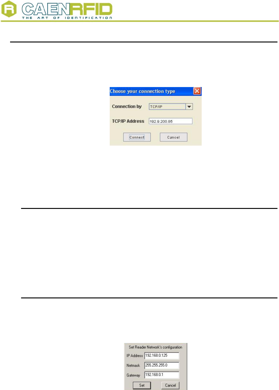
Once you have connected the CAEN UHF RFID Reader to your PC, turn it ON, then:
Click on File > Open connection
The following pop-up window will open:
Fig. 2.3 – Connection port configuration
Choose the connection type; if you are using TCP-IP enter the IP address (default
address: 192.168.0.125), if you are using RS232, type the connected port (COM1,
COM2…) then click on <Connect>. If you wish to use RS232 or USB, please make sure
that the Java Platform you are running supports such ports.
2.3.1. Reader protocol configuration
Optionally, it is possible to change the used protocol (ISO18000-6B or EPC
C1G1/C1G2);
click on configuration > change reader’s protocol
A pop-up window will allow to chose between ISO18000-6B (which supports also Philips
UCODE EPC 1.19) and EPC C1G1.
If the protocol is changed, a reader reboot will be performed; then it is necessary to shut
and re-start the CAEN RFID Demo program.
2.3.2. Network configuration
Optionally, it is possible to update the reader’s network settings;
click on
configuration > network setup
The following pop-up window will open (the figure shows the default configuration):
Fig. 2.4 – Reader Network configuration
NPO: Filename: Number of pages: Page:
00117/03:Demox.MUTx/01 RFIDDEMO_REV1.DOC 27 8
Document type: Title: Revision date: Revision:
User's Manual (MUT) RFID Software User Interface 18/02/2006 1
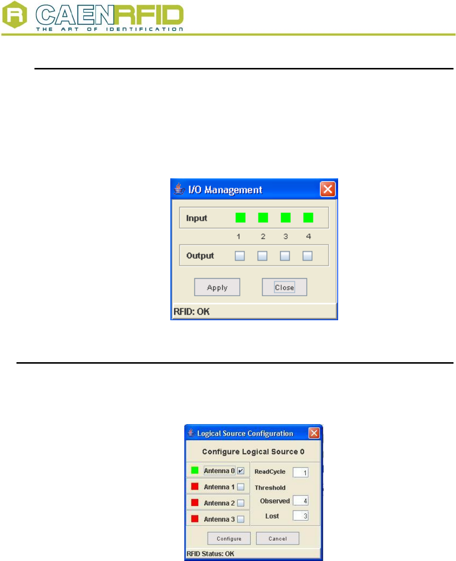
2.3.3. Input output management
This function allows to handle the reader general purpose inputs/outputs;
click on
configuration > I/O Management
The following pop-up window will open:
By checking the Output boxes, the relevant signal will be driven high. The Input status is
also monitored: red = active, green = idle.
Fig. 2.5 – Reader Network configuration
2.4. Logical source selection
Click on configuration > configure logical source
The following pop-up window will open:
Fig. 2.6 – Logical source selection and test
the antenna(s) status is checked:
BAD (antenna not connected) = RED
POOR (antenna with faulty operation) = YELLOW
GOOD (antenna ok) = GREEN
Then choose the antenna(s) you wish to use.
Finally it is necessary to set the thresholds:
Observed:
READCYCLE MODE (see §2.5): the number of subsequent times a tag must appear in
an acquisition before it shifts from “glimpsed” to “observed”
NPO: Filename: Number of pages: Page:
00117/03:Demox.MUTx/01 RFIDDEMO_REV1.DOC 27 9
Document type: Title: Revision date: Revision:
User's Manual (MUT) RFID Software User Interface 18/02/2006 1
TIME MODE (see §2.5): the number of milliseconds a tag must appear in an acquisition
before it shifts from “glimpsed” to “observed”
Lost:
READCYCLE MODE: the number of subsequent times an observed tag must disappear
from an acquisition before it shifts from “observed”” to “lost”
TIME MODE: the number of milliseconds an observed tag must disappear from an
acquisition before it shifts from “observed”” to “lost”
Read Cycle: the number of times an acquisition must be timed out and then restarted
Confirm settings by clicking on <Configure>.
Thresholds are meaningful only with Asynchronous Acquisition (see § 2.5)
2.5. Detecting test tags with the RF field
Now the Reader is ready for detecting tags; click on either:
<Synchronous Acquisition>
<Asynchronous Acquisition>
With Synchronous Acquisition, a “one shot” readout is performed.
Asynchronous Acquisition allows to perform either Timed Acquisition or a I/O Timed-
out acquisition.
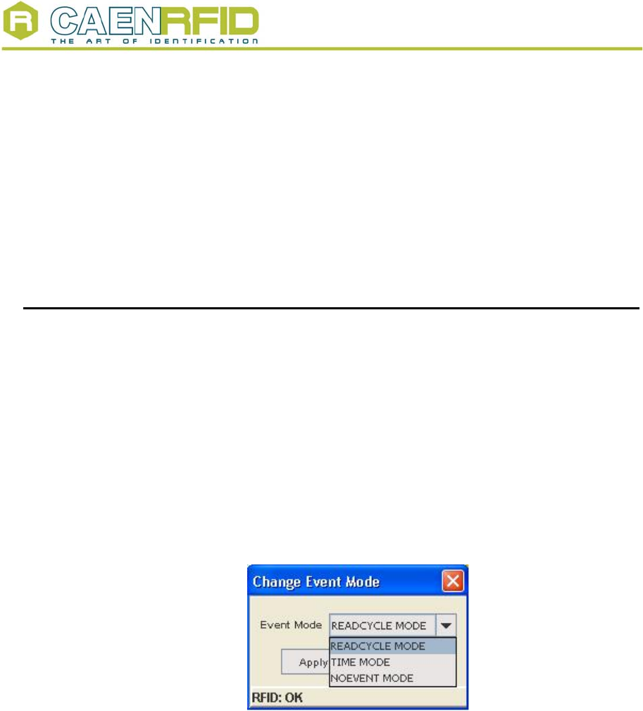
In the first place it is necessary to set the “Event mode” by clicking on:
Configuration>Configure Event Mode
The following window opens:
Fig. 2.7 – Event mode configuration
If READCYCLE MODE is selected, the logical source thresholds are expressed in cycles,
whose duration is equal to the Delay time set when Asynchronous Acquisition is
launched.
If TIME MODE is selected, the logical source thresholds are expressed in milliseconds; it
must be noticed that the thresholds might not be multiple of the delay time, so a tag can
change its status after a non-integer number of cycles.
If NOEVENT MODE is selected, the tags are continuously scanned, the threshold values
are meaningless (the tag is considered either inside or outside the reader’s field and no
Glimpsed/Observed status is notified)
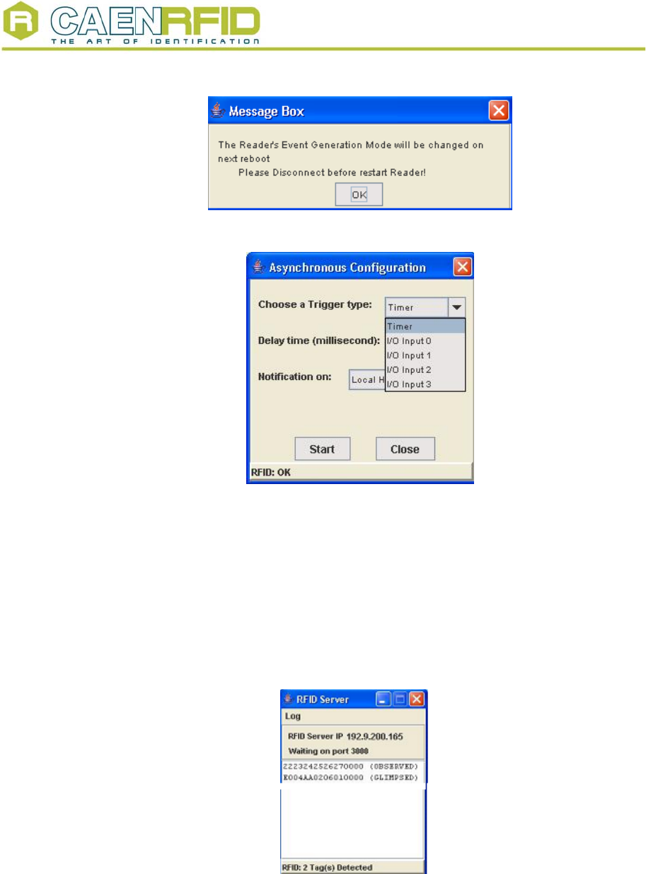
After changing Event Mode it is necessary to restart both the Reader and the RFID
Demo Java Version. The following message will be shown:
NPO: Filename: Number of pages: Page:
00117/03:Demox.MUTx/01 RFIDDEMO_REV1.DOC 27 10
Document type: Title: Revision date: Revision:
User's Manual (MUT) RFID Software User Interface 18/02/2006 1
Fig. 2.8 – Change Event mode message
Fig. 2.9 – Asynchronous Acquisition configuration
If you wish to make a Timed Acquisition in READCYCLE MODE:
− choose “Timer” as trigger type in the drop down menu of the Asynchronous
Configuration which is started as Asynchronous Acquisition is selected.
− set the timer period in “Delay time” field
− set the notification on Local or Remote host: in the latter case you have to enter the
host IP address
− “Start” acquisition
The notification takes place on the RFID Server window, which is shown either on the
Local host or on the Remote one:
Fig. 2.10 – RFID Server
If you wish to make a I/O Timed-out Acquisition in READCYCLE MODE:
− choose the General Purpose Input you wish to use as trigger type in the drop down
menu of the Asynchronous Configuration.
− set the time out delay in “Delay time” field
NPO: Filename: Number of pages: Page:
00117/03:Demox.MUTx/01 RFIDDEMO_REV1.DOC 27 11
Document type: Title: Revision date: Revision:
User's Manual (MUT) RFID Software User Interface 18/02/2006 1
− set the notification on Local or Remote host: in the second case you have to enter
the host IP address
− “Start” acquisition
The notification takes place on the RFID ServerConfiguration; after the first acquisition
the Reader waits for one “Delay time” period, then checks the status of the used input: if
it is high, then the second acquisition takes place, otherwise it is timed out; at this point
the Reader waits for another Delay time, then checks the status of the used input again.
If you wish to make a Timed Acquisition in TIME MODE:
− choose “Timer” as trigger type in the drop down menu of the Asynchronous
Configuration which is started as Asynchronous Acquisition is selected.
− set the timer period in “Delay time” field
− set the notification on Local or Remote host: in the latter case you have to enter the
host IP address
− “Start” acquisition
The notification takes place on the RFID Server window, which is shown either on the
Local host or on the Remote one. The status does not depend on the number of
performed cycles, but ONLY on the threshold values (see §2.4); the “Delay time” must be
smaller than the thresholds.
If you wish to make an acquisition in NOEVENT MODE, simply :
− set the timer period in “Delay time” field
− set the notification on Local or Remote host: in the latter case you have to enter the
host IP address
− “Start” acquisition
The notification takes place on the RFID Server window, which is shown either on the
Local host or on the Remote one, no status is notified.
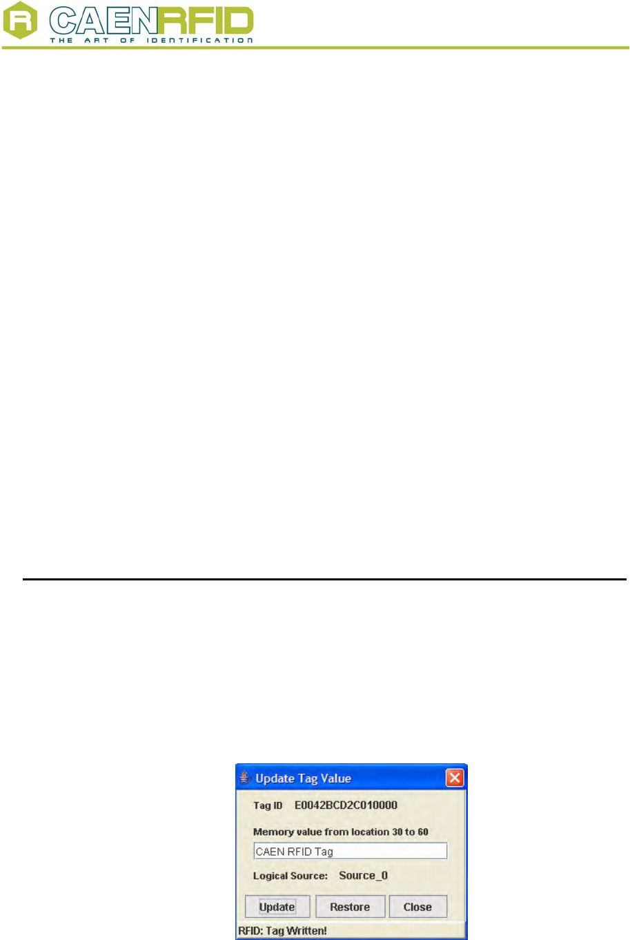
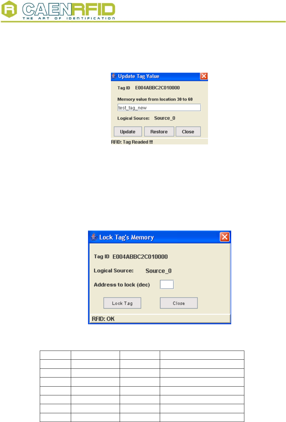
2.6. Readout of one tag’s memory
Now the ISO18000-6B detected tags are ready for read/write operations. In case of
Timed, Continuous or I/O Acquisition it is necessary to stop scanning, by clicking on the
stop acquisition button. Now click on one of the tags’ Unique ID’s; then go to:
Features
>ISO18000-6B
>Read/Write Tag Memory
The following window is shown:
Fig. 2.11 – Tags memory
NPO: Filename: Number of pages: Page:
00117/03:Demox.MUTx/01 RFIDDEMO_REV1.DOC 27 12
Document type: Title: Revision date: Revision:
User's Manual (MUT) RFID Software User Interface 18/02/2006 1
By writing in the Value field, it is possible to update the tag memory; changes are saved
via the <Update> button, while <Restore> allows to recover the former value.
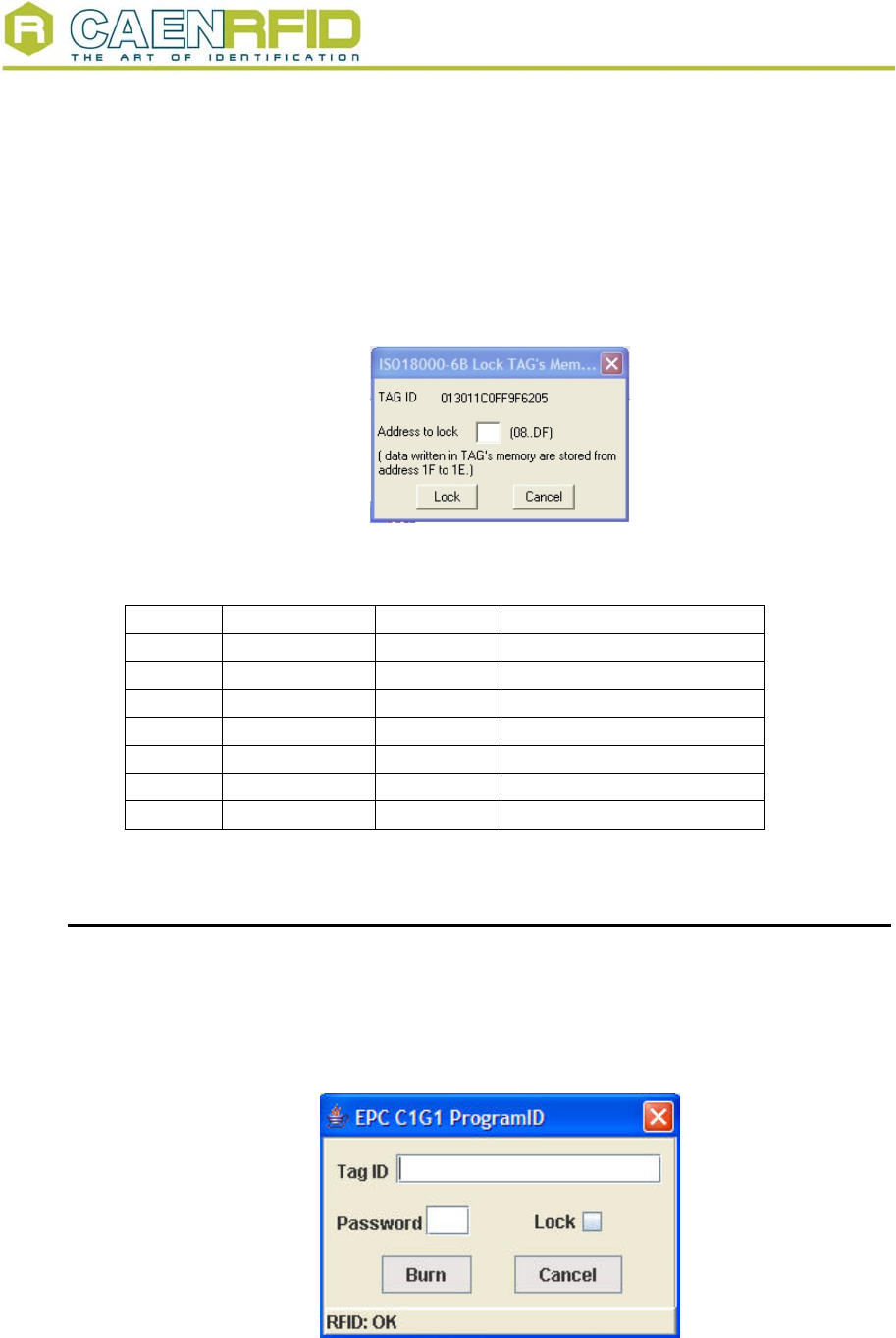
In order to lock one particular address in the tag memory, go to:
Features
>ISO18000-6B
>Lock
The following window is shown; <Lock> allows to lock one particular address, <Cancel>
to quit. Locked addresses cannot be changed anymore.
Fig. 2.12 – Tag readout
The configuration of the ISO18000-6B compliant tags is the following:
Byte Content Status Description
0,1 E0, 04 hex locked Unique serial number
2÷7 xx hex locked Unique serial number
8÷10 00 hex unlocked User memory
11 02 hex unlocked User memory
12÷17 FF hex unlocked User memory
18÷219 00 hex unlocked User memory
220÷223 57 5F 4F 4B hex unlocked “w_ok” in ASCII, user memory
The CAEN RFID Demo program allows to write only bits [2; 17].
2.6.1. EPC protocol tags operations
If EPC tags are detcted, then go to:
Features
>EPC
>Program ID
For (over)writing the tags ID, setting the password, and locking them:
Fig. 2.13 – Tag programming
NPO: Filename: Number of pages: Page:
00117/03:Demox.MUTx/01 RFIDDEMO_REV1.DOC 27 13
Document type: Title: Revision date: Revision:
User's Manual (MUT) RFID Software User Interface 18/02/2006 1
Go to:
Features
>EPC
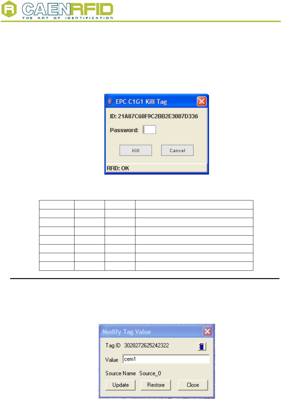
>Kill
For killing the tag (the password is required). Once killed the tag does not respond to
(any) reader anymore.
Fig. 2.14 – Tag killing
The configuration of the EPC Class 1 Gen 1 compliant tags is the following:
Byte Type Status Description
00, 01 hex System locked Tag header
02 hex System unlocked EPC portion
03÷07 hex System unlocked EPC portion
08÷0F hex System unused
10÷17 hex System unlocked EPC portion
18÷37 hex User unlocked User memory (256 bit)
38÷FF hex RFU
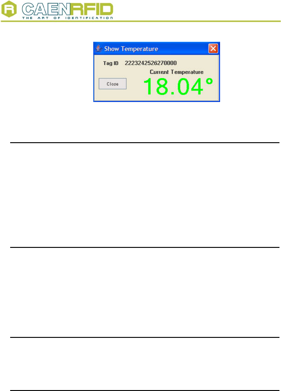
2.7. Temperature monitoring with the semipassive tag
The semipassive tag Mod. A927 includes a temperature sensor; so it is possible to view
the temperature parameter as a function of time. This is possible by clicking on the
termometer icon.
Fig. 2.15 – Temperature monitoring/1
A pop-up window with the temperature trace will be then shown:
NPO: Filename: Number of pages: Page:
00117/03:Demox.MUTx/01 RFIDDEMO_REV1.DOC 27 14
Document type: Title: Revision date: Revision:
User's Manual (MUT) RFID Software User Interface 18/02/2006 1
Fig. 2.16 – Temperature monitoring/2
Status: Green = tag inside reader’s field
Red = tag outside reader’s field
2.8. Creating the Log file
Click on
configuration > Enable logging
Then start the “Continuous acquisition”.
When the acquisition is stopped, it will be possible to save the log text file, containing
information on the detected tags, for example:
Tue Apr 19 11:01:19.011 e004840306010000 Glimpsed
Tue Apr 19 11:01:19.101 e004840306010000 Glimpsed
Tue Apr 19 11:01:19.201 e004840306010000 Glimpsed
N.B.: creating the Log file is possible only with “Continuous acquisition”
2.9. RF Field test
It is possible to test the RF field emissions in the following way:
Click on
configuration > select test & read point
Then select the read point to be tested (0..3).
Go to the main menu, then set the desired power and choose “single acquisition”.
Click on
configuration > experimental > RF ON
It is now possible to test the RF field emission on the selected read point.
In order to test another read point it is necessary to repeat the procedure from the start.
2.10. Quit CAEN RFID Demo program
For quitting the CAEN RFID Demo program click on
File > exit
Then turn off the reader and disconnect the antenna cable, the power cord and the link
cable.
2.11. ISO18000-6B protocol tags operations
The ISO18000-6B detected tags are ready for read/write operations. It is necessary to
stop scanning, by clicking on the stop acquisition button. Now click on one of the tags’
Unique ID’s; then go to:
NPO: Filename: Number of pages: Page:
00117/03:Demox.MUTx/01 RFIDDEMO_REV1.DOC 27 15
Document type: Title: Revision date: Revision:
User's Manual (MUT) RFID Software User Interface 18/02/2006 1
Features
>ISO18000-6B
>Read/Write Tag Memory
The following window is shown:
Fig. 2.17 – ISO18000-6B Tags memory
By writing in the Value field, it is possible to update the tag memory; changes are saved
via the <Update> button, while <Restore> allows to recover the former value.
In order to lock one particular address in the tag memory, go to:
Features
>ISO18000-6B
>Lock
The following window is shown; <Lock> allows to lock one particular address, <Cancel>
to quit. Locked addresses cannot be changed anymore.
Fig. 2.18 – ISO18000-6B Tag readout
The configuration of the ISO18000-6B compliant tags is the following:
Byte Content Status Description
0,1 E0, 04 hex locked Unique serial number
2÷7 xx hex locked Unique serial number
8÷10 00 hex unlocked User memory
11 02 hex unlocked User memory
12÷17 FF hex unlocked User memory
18÷219 00 hex unlocked User memory
220÷223 57 5F 4F 4B hex unlocked “w_ok” in ASCII, user memory
The CAEN RFID Demo program allows to write only bits [2; 17].
NPO: Filename: Number of pages: Page:
00117/03:Demox.MUTx/01 RFIDDEMO_REV1.DOC 27 16
Document type: Title: Revision date: Revision:
User's Manual (MUT) RFID Software User Interface 18/02/2006 1
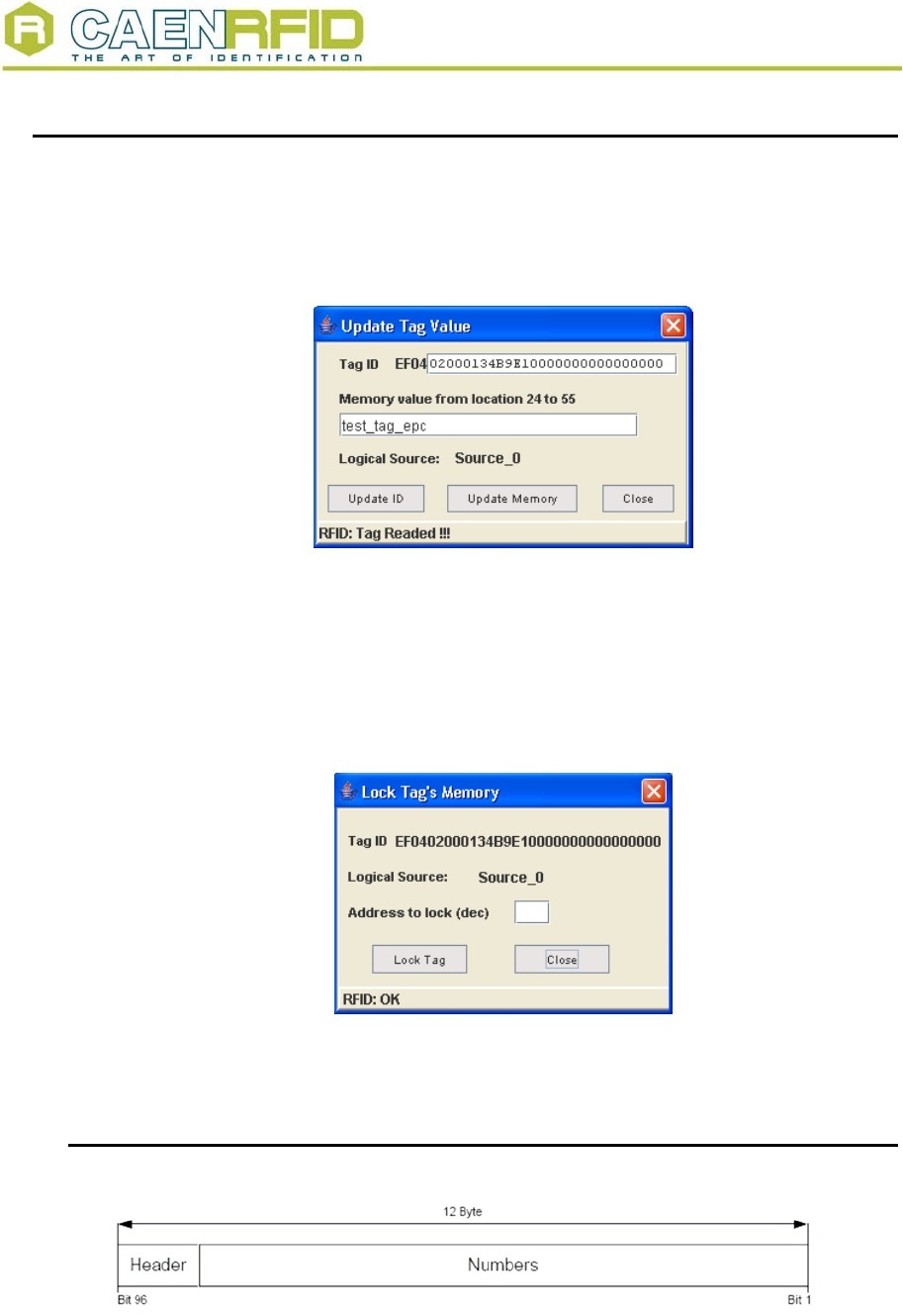
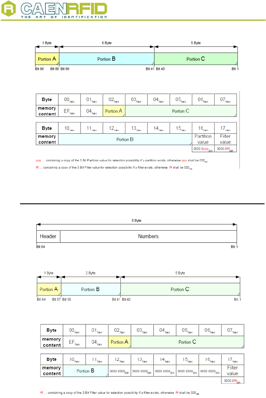
2.12. EPC1.19 protocol tags operations
If EPC1.19 tags are detected, then go to:
Features
>EPC1.19
> Read/Write Tag Memory
For (over)writing the tags ID and Memory:
Fig. 2.19 – EPC1.19 Tag programming
In order to lock one particular address in the tag memory, go to
Go to:
Features
>EPC1.19
>Lock
The following window is shown; <Lock> allows to lock one particular address, <Cancel>
to quit. Locked addresses cannot be changed anymore.
Fig. 2.20 – EPC1.19 Tag locking
The configuration of the EPC 1.19 compliant tags is the following:
2.12.1. EPC 1.19 Tag Data memory mapping (96 bit)
Fig. 2.21 – General structure of 96 bit EPC number
NPO: Filename: Number of pages: Page:
00117/03:Demox.MUTx/01 RFIDDEMO_REV1.DOC 27 17
Document type: Title: Revision date: Revision:
User's Manual (MUT) RFID Software User Interface 18/02/2006 1
Fig. 2.22 – Separation of 96 bit data structure for UCODE EPC 1.19
Fig. 2.23 – Mapping of 96 bit data structure into UCODE EPC 1.19 memory
2.12.2. EPC 1.19 Tag Data memory mapping (64 bit)
Fig. 2.24 – General structure of 64 bit EPC number
Fig. 2.25 – Separation of 64 bit data structure for UCODE EPC 1.19
Fig. 2.26 – Mapping of 64 bit data structure into UCODE EPC 1.19 memory
NPO: Filename: Number of pages: Page:
00117/03:Demox.MUTx/01 RFIDDEMO_REV1.DOC 27 18
Document type: Title: Revision date: Revision:
User's Manual (MUT) RFID Software User Interface 18/02/2006 1
3. Firmware upgrade
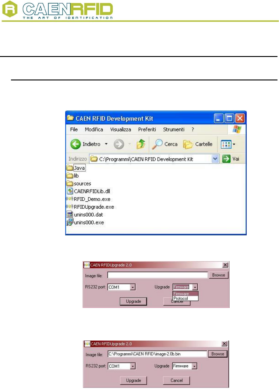
3.1. Firmware upgrade via serial port
In order to upgrade the Reader firmware, connect the it with the PC Host via RS232, then
open the following directory:
Fig. 3.1 – CAEN RFID DEMO directories
Now launch RFIDUpgrade.exe:
Fig. 3.2 – CAEN RFIDUpgrade/1
Select “Firmware” in the Upgrade Menu and the connected port, then Browse the image
file to be uploaded (for example: image-2.0b.bin):
Fig. 3.3 – Selecting the image file
Now click on <Upgrade>; it will take 10 minutes for uploading the updated firmware and
rebooting the Reader; when the Reader is ready the ISO/EPC and the Active leds will
light up: do not turn off the Reader before the Active led lights on and then off!
NPO: Filename: Number of pages: Page:
00117/03:Demox.MUTx/01 RFIDDEMO_REV1.DOC 27 19
Document type: Title: Revision date: Revision:
User's Manual (MUT) RFID Software User Interface 18/02/2006 1
The image file can be found in the Upgrade_img_file directory of the “Driver, Demo
software and Technical manuals” CD ROM (included in the RFID Development Kit); it
can also be downloaded at: http://www.caen.it/rfid/english/download.php
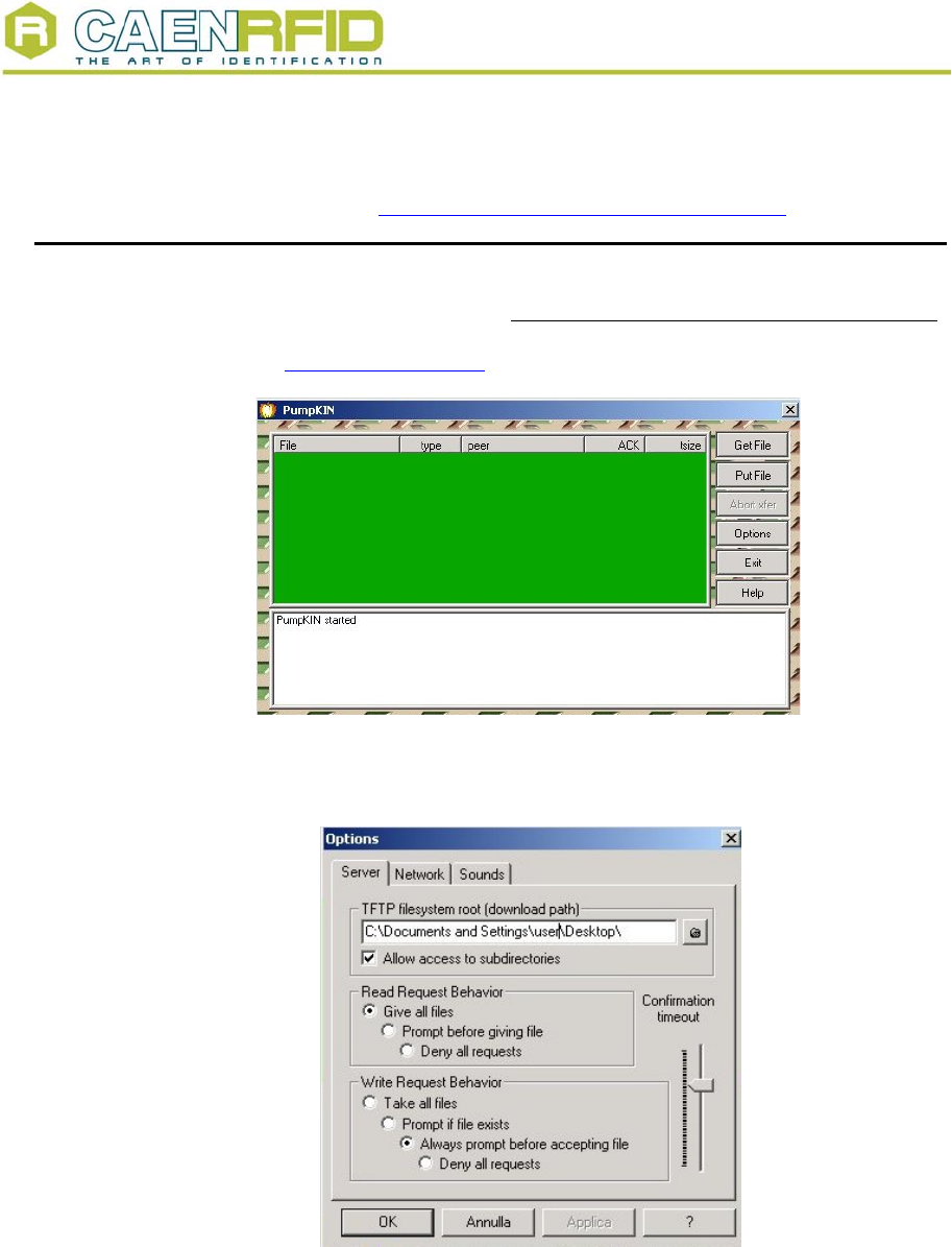
3.2. Firmware upgrade via TCP/IP
The Firmware upgrade via TCP/IP works only with the CAENRFID Demo Java Version.
First you need a TFTP Server & Client application, if you have not one installed, you can
download (from http://www.klever.net/ ), install and run the pumpkin.exe freeware
application:
Fig. 3.4 – PumpKIN Menu Window
Select [Options] and browse the folder where the image file resides with the following
selections, then press [OK]
Fig. 3.5 – PumpKIN Options Window
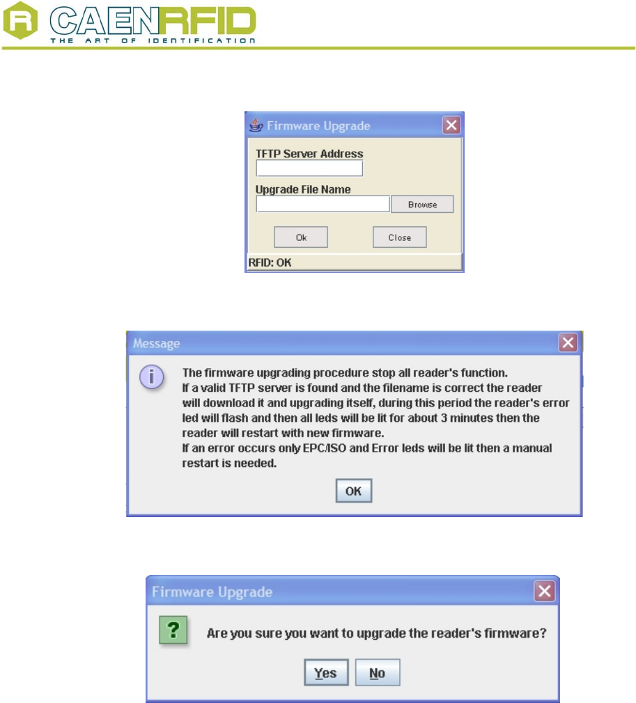
Connect to the Reader by using CAEN RFID Demo Java version and select
Configuration>Firmware Upgrade
enter the TFTP server address and browse the image file to be loaded into the Reader,
then press [OK]:
NPO: Filename: Number of pages: Page:
00117/03:Demox.MUTx/01 RFIDDEMO_REV1.DOC 27 20
Document type: Title: Revision date: Revision:
User's Manual (MUT) RFID Software User Interface 18/02/2006 1
Fig. 3.6 – Firmware upgrade browser
The following information message will then be shown:
Fig. 3.7 – Firmwareupgrade message
Press ok and this confirmation message will be returned:
Fig. 3.8 – Confirmation message
Press YES then Download image via TFTP; the Firmware Upgrade is then completed.
NPO: Filename: Number of pages: Page:
00117/03:Demox.MUTx/01 RFIDDEMO_REV1.DOC 27 21
Document type: Title: Revision date: Revision:
User's Manual (MUT) RFID Software User Interface 18/02/2006 1
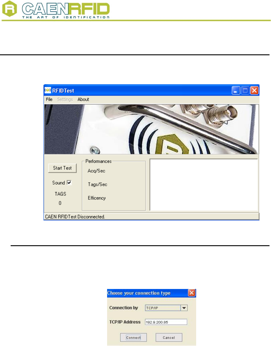
4. RFID Test program
This is a simple VisualC++ test program: go to the main directory CAEN RFID DEMO
KIT, then launch the TestRFID.exe executable file; the following Menu will be launched:
Fig. 4.1 – RFID Test main menu
4.1. Connection configuration
Once you have connected the CAEN UHF RFID Reader to your PC, turn it ON, then:
Click on File > Connect
The following pop-up window will open:
Fig. 4.2 – Connection port configuration
Choose the connection type; if you are using TCP-IP enter the IP address (default:
192.168.0.125), if you are using RS232, type the connected port (COM1, COM2…) then
click on <Connect>.
NPO: Filename: Number of pages: Page:
00117/03:Demox.MUTx/01 RFIDDEMO_REV1.DOC 27 22
Document type: Title: Revision date: Revision:
User's Manual (MUT) RFID Software User Interface 18/02/2006 1
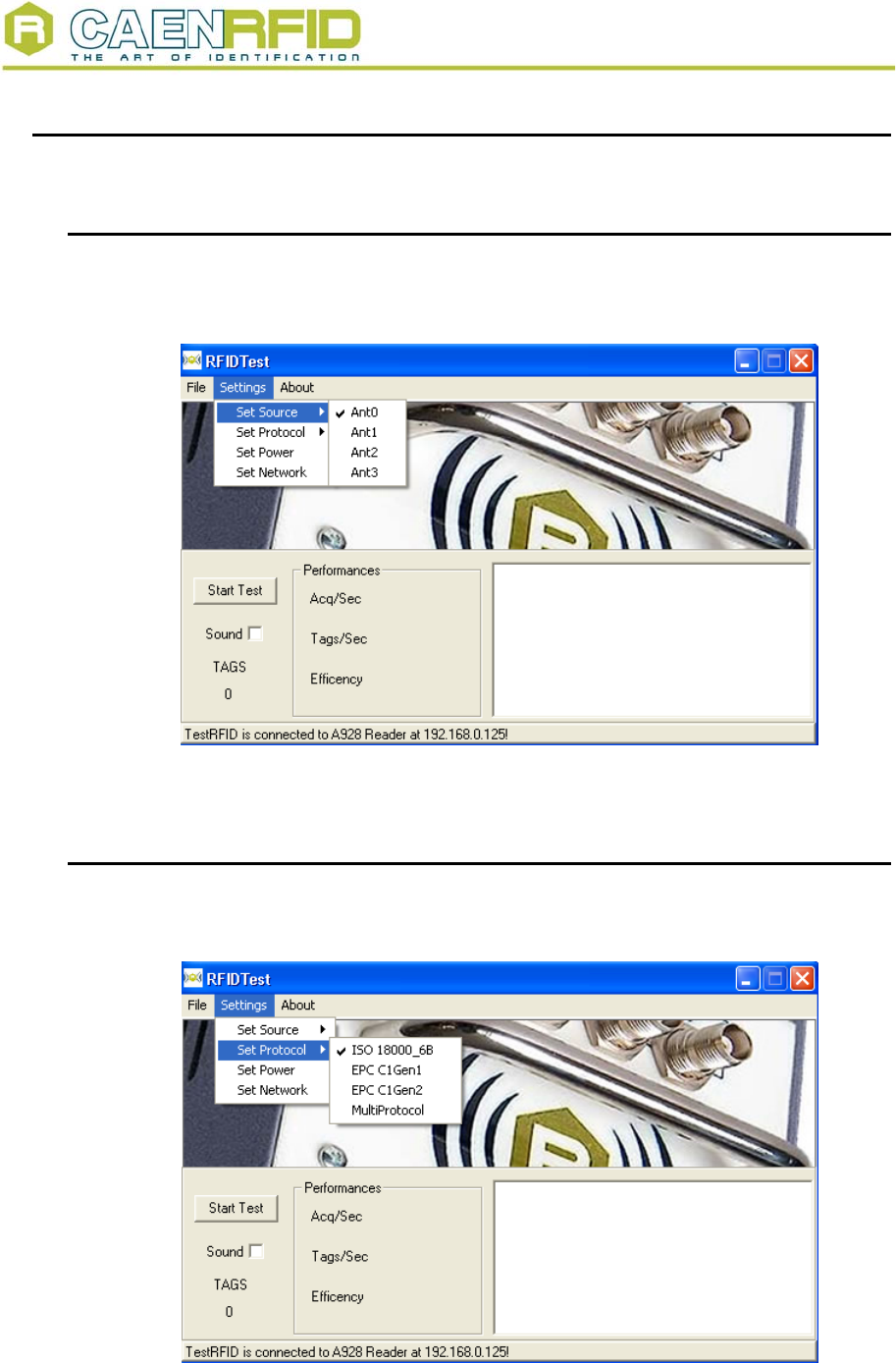
4.2. Settings
4.2.1. Antenna selection
Click on
settings > set source ; then flag the antenna(s) you wish to use
Fig. 4.3 – Source selection
4.2.2. Protocol selection
Click on
settings > set source; then flag the protocol you wish to use
Fig. 4.4 – Setting the protocol
NPO: Filename: Number of pages: Page:
00117/03:Demox.MUTx/01 RFIDDEMO_REV1.DOC 27 23
Document type: Title: Revision date: Revision:
User's Manual (MUT) RFID Software User Interface 18/02/2006 1
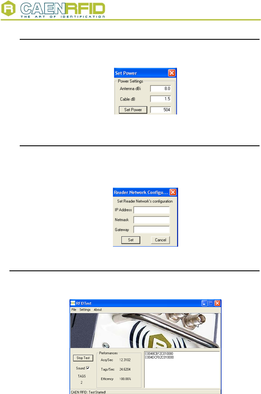
4.2.3. Power settings
Click on
settings > set source; then type the power settings you wish to use
Fig. 4.5 – Power settings fields
4.2.4. Reader network configuration
Optionally, it is possible to update the reader’s network settings;
click on
settings > set network
The following pop-up window will open (the figure shows the default configuration):
Fig. 4.6 – Network configuration
4.3. Start Test
Now click on « Start Test »: the name of the tags in the reader’s field will be shown. Click
on «Stop test» in order to stop acquisition.
Fig. 4.7 – Tags detection
NPO: Filename: Number of pages: Page:
00117/03:Demox.MUTx/01 RFIDDEMO_REV1.DOC 27 24

Document type: Title: Revision date: Revision:
User's Manual (MUT) RFID Software User Interface 18/02/2006 1
4.4. Quit CAEN RFID Test program
For quitting the CAEN RFID Test program click on
File > exit
Then turn off the reader and disconnect the antenna cable, the power cord and the link
cable.
NPO: Filename: Number of pages: Page:
00117/03:Demox.MUTx/01 RFIDDEMO_REV1.DOC 27 25
Document type: Title: Revision date: Revision:
User's Manual (MUT) RFID Software User Interface 18/02/2006 1
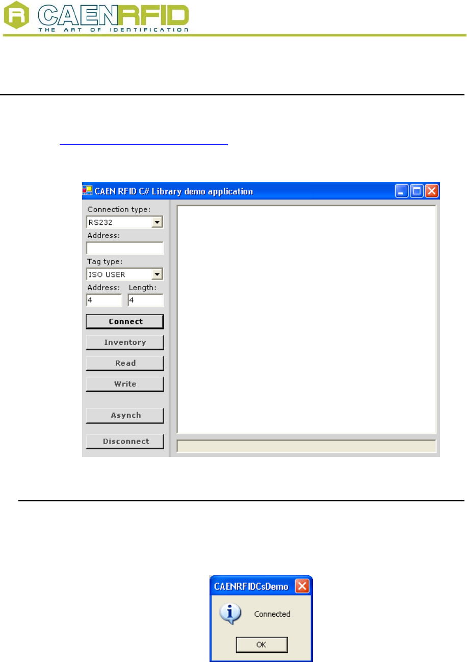
5. RFID CsDemo program
This is a simple RFID .Net Sample program. First of all, go to:
http://www.microsoft.com/downloads/
then download and install on your PC the DotNet Framework 1.1
Then go to the main directory CAEN RFID DEMO KIT, then launch the
CAENRFIDCsDemo.exe executable file; the following Menu will be launched:
Fig. 5.1 – RFID Test main menu
5.1. Connection configuration
Once you have connected the CAEN UHF RFID Reader to your PC, turn it ON, then:
Choose the connection type; if you are using TCP-IP enter the IP address (default:
192.168.0.125), if you are using RS232, type the connected port (COM1, COM2…) then
click on <Connect>. The following pop-up window will open:
Fig. 5.2 – Connection confirmation
NPO: Filename: Number of pages: Page:
00117/03:Demox.MUTx/01 RFIDDEMO_REV1.DOC 27 26
Document type: Title: Revision date: Revision:
User's Manual (MUT) RFID Software User Interface 18/02/2006 1
5.2. Start inventory
Select the tag type you want to read, then click on « Inventory »: the name of the tags in
the reader’s field will be shown. Click on «Disconnect» in order to stop acquisition.
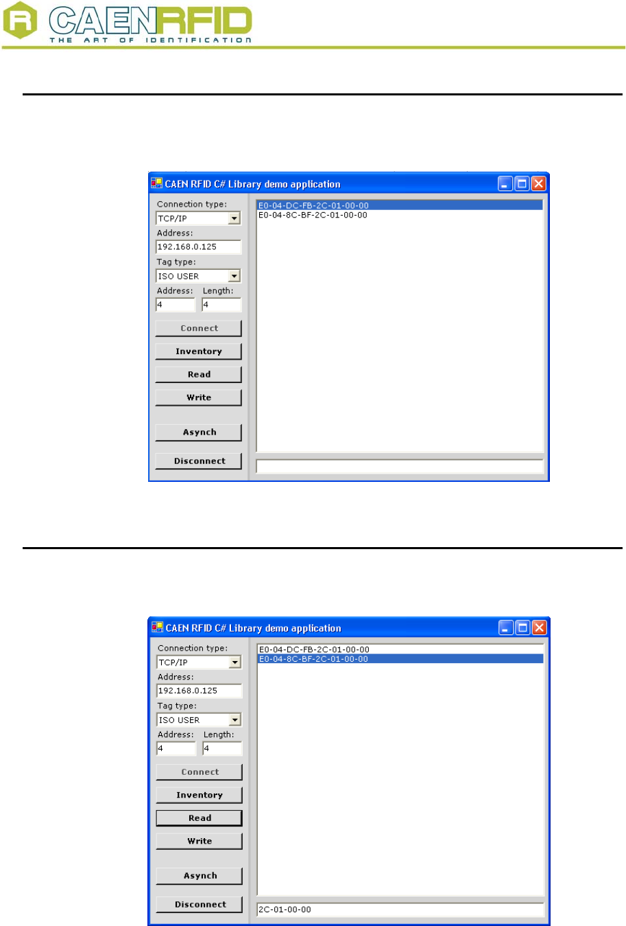
Fig. 5.3 – Tags detection
5.3. Read tags memory
Select the tag type you want to read, then click on «Read»: the memory content of the
tags in the reader’s field will be shown.
Fig. 5.4 – Tags memory readout
NPO: Filename: Number of pages: Page:
00117/03:Demox.MUTx/01 RFIDDEMO_REV1.DOC 27 27