CalAmp Wireless Networks MCUC5 Integra 900 MHz Radio-Modem User Manual technical manual first released version
CALAMP WIRELESS NETWORKS INC. Integra 900 MHz Radio-Modem technical manual first released version
UserManual.wiki
>
CalAmp Wireless Networks
>
MCUC5 User Manual
technical manual first released version
Navigation menu
Upload a User Manual
Namespaces
Wiki Guide
HTML
PDF
Info
Views
User Manual
Discussion / Help
Navigation
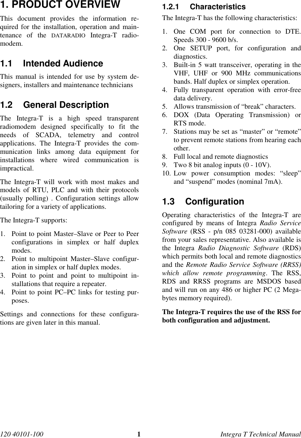
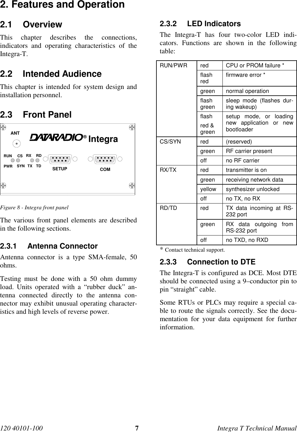
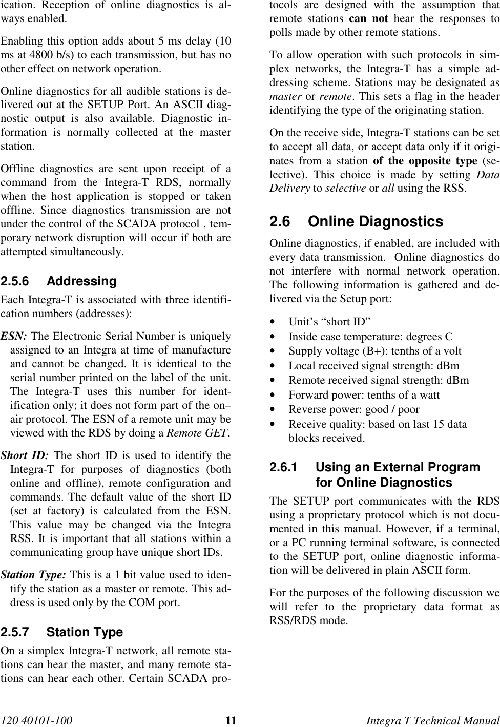
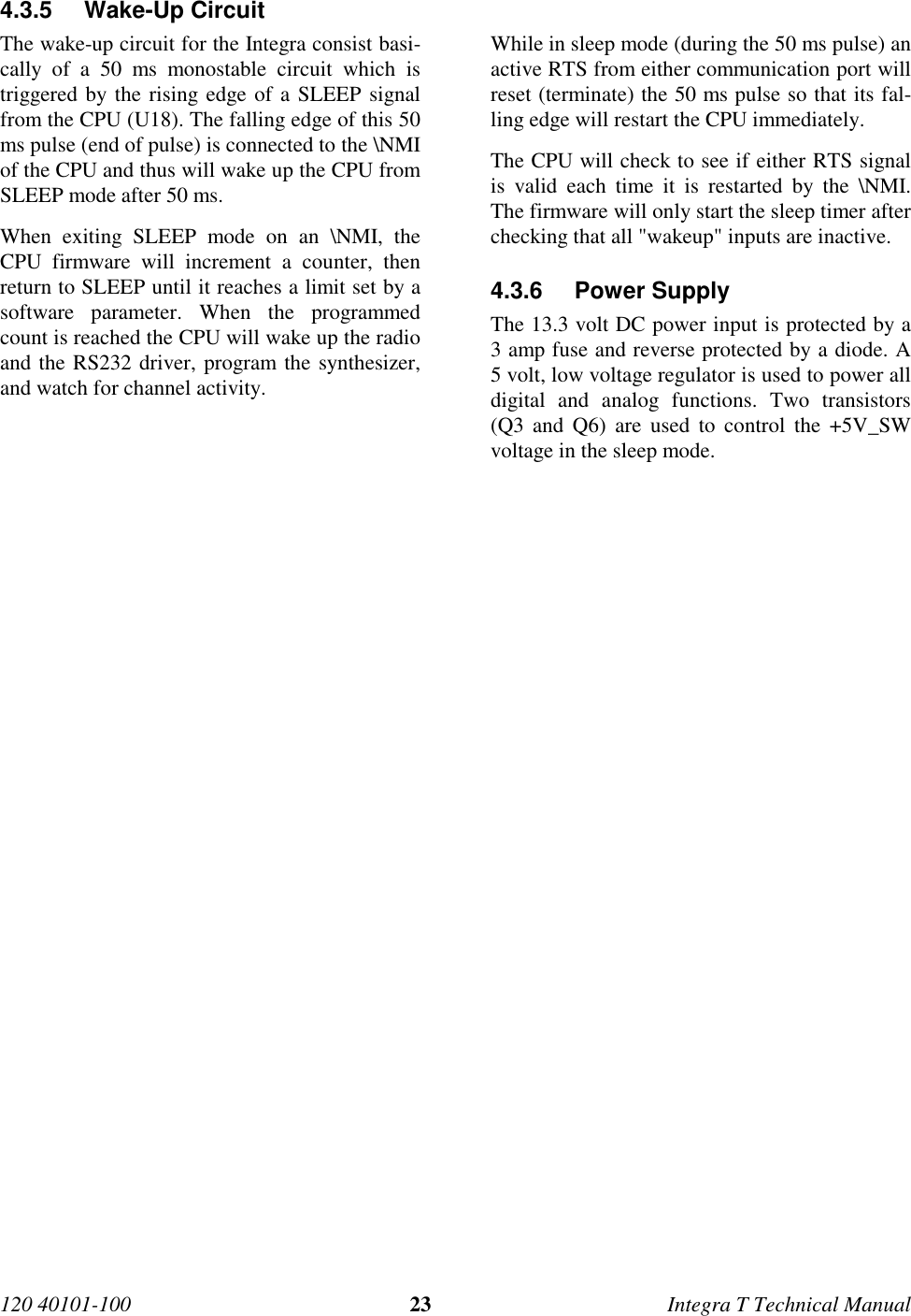
![120 40101-100 2Integra T Technical Manual 1.4 Catalog Numbers An Integra-T may be identified from its catalognumber.CATALOG NUMBERSFormat is INA [radio][band][channel spacing]0-Tradio 22 12 92freq VHF UHF 900power 5 W 5 W 5 Wband1 380 - 4032 403 - 4193 419 - 4354 132 - 150 435 - 4515 150 - 174 450 - 470 928 - 9606 464 - 4807 480 - 4968 496 - 512channel spacing3 30.0 25.0 25.0For example, an INA12530-T is an Integra-T, operating inthe 450-470 MHz band with 25 kHz channel spacing 1.5 Factory Technical Support The Technical Support departments ofDATARADIO and Johnson Data Telemetry (JDT)provide customer assistance on technical prob-lems and serve as an interface with factory re-pair facilities. Technical support hours are 9:00AM to 5:00 PM, Eastern Time, Monday to Fri-day. Technical support can be reached in thefollowing ways: DATARADIO Inc. 5500 Royalmount Ave, suite 200 Town of Mount Royal Quebec, Canada H4P 1H7 phone: +1 514 737-0020 fax: +1 514 737-7883Email address: support@dataradio.com Johnson Data Telemetry Corp. Customer Service Department 299 Johnson Avenue, P.O. Box 1733 Waseca, MN 56093-0833 phone: 800 992-7774 and +1 507 835-6911 fax: 507 835-6969Email address: support@johnsondata.com1.6 Product Warranty Warranty information may be obtained by con-tacting your sales representative.1.7 Replacement Parts This product is normally not field serviceable,except by the replacement of complete units.Specialized equipment and training is requiredto repair logic boards and radio modules. Contact Technical Support for service informa-tion before returning equipment. A TechnicalSupport representative may suggest a solutioneliminating the need to return equipment.1.7.1 Factory Repair When returning equipment for repair, you mustrequest an RMA (returned merchandise authori-zation) number. The Tech Support representa-tive will ask you several questions to clearlyidentify the problem. Please give the represen-tative the name of a contact person who is fa-miliar with the problem, in case questions ariseduring servicing of the unit. Customers are responsible for shipping chargesfor returned units. Units in warranty will be re-paired free of charge unless there is evidence ofabuse or damage beyond the terms of the war-ranty. Units out of warranty will be subject toservice charges. Information about these chargesis available from Technical Support.](https://usermanual.wiki/CalAmp-Wireless-Networks/MCUC5/User-Guide-8817-Page-8.png)