CalAmp Wireless Networks MCUC5 Integra 900 MHz Radio-Modem User Manual technical manual first released version
CALAMP WIRELESS NETWORKS INC. Integra 900 MHz Radio-Modem technical manual first released version
technical manual first released version

Integra-T
Technical Manual
version 1.00
The entire contents of this manual and the Software described
in this manual are copyright 1998 by DATARADIO Inc.
Copyright DATARADIO Inc.
May 1998
part no.: 120 40101-100
i
Table of Contents
1. PRODUCT OVERVIEW................................................................................................................................... 1
1.1 INTENDED AUDIENCE ....................................................................................................................................... 1
1.2 GENERAL DESCRIPTION .................................................................................................................................... 1
1.2.1 Characteristics ........................................................................................................................................ 1
1.3 CONFIGURATION ............................................................................................................................................... 1
1.4 CATALOG NUMBERS ......................................................................................................................................... 2
1.5 FACTORY TECHNICAL SUPPORT........................................................................................................................ 2
1.6 PRODUCT WARRANTY ...................................................................................................................................... 2
1.7 REPLACEMENT PARTS....................................................................................................................................... 2
1.7.1 Factory Repair........................................................................................................................................ 2
1.8 PHYSICAL DESCRIPTION.................................................................................................................................... 3
1.9 DIAGNOSTICS.................................................................................................................................................... 3
1.9.1 Remote Commands.................................................................................................................................. 3
1.10 FIRMWARE UPGRADES ................................................................................................................................. 3
1.11 NETWORK APPLICATION............................................................................................................................... 3
1.11.1 RF Path and Communications Range................................................................................................. 3
1.11.2 Basic Connections .............................................................................................................................. 4
1.11.3 Common Characteristics .................................................................................................................... 4
1.11.4 Point to Point System.......................................................................................................................... 4
1.11.5 Point–Multipoint System..................................................................................................................... 4
1.11.6 Repeaters ............................................................................................................................................ 5
1.11.6.1 All Stations Use the Repeater..........................................................................................................................5
1.11.6.2 Some Stations Use the Repeater......................................................................................................................5
1.11.7 Extending a Landline (Tail Circuit).................................................................................................... 6
2. FEATURES AND OPERATION...................................................................................................................... 7
2.1 OVERVIEW........................................................................................................................................................ 7
2.2 INTENDED AUDIENCE ....................................................................................................................................... 7
2.3 FRONT PANEL ................................................................................................................................................... 7
2.3.1 Antenna Connector ................................................................................................................................. 7
2.3.2 LED Indicators........................................................................................................................................ 7
2.3.3 Connection to DTE.................................................................................................................................. 7
2.3.3.1 Connector Pinout.............................................................................................................................................8
2.3.4 Com Port................................................................................................................................................. 8
2.3.4.1 3 Wire Connection (DOX) ..............................................................................................................................8
2.3.5 Setup Port................................................................................................................................................ 8
2.4 REAR PANEL..................................................................................................................................................... 9
2.4.1 Heat Sink................................................................................................................................................. 9
2.4.2 Power / Analog connector....................................................................................................................... 9
2.4.2.1 Power ..............................................................................................................................................................9
2.4.2.2 Power / Analog cable ......................................................................................................................................9
2.4.2.3 Analog inputs ..................................................................................................................................................9
2.5 OPERATION..................................................................................................................................................... 10
2.5.1 Operating Modes................................................................................................................................... 10
2.5.2 Data Forwarding Timer........................................................................................................................ 10
2.5.3 Sending Break Signals .......................................................................................................................... 10
2.5.4 COM Port Baud Rates .......................................................................................................................... 10
2.5.5 Diagnostics............................................................................................................................................ 10
2.5.6 Addressing............................................................................................................................................. 11
2.5.7 Station Type........................................................................................................................................... 11
ii
2.6 ONLINE DIAGNOSTICS..................................................................................................................................... 11
2.6.1 Using an External Program for Online Diagnostics............................................................................. 11
2.6.1.1 Initialization ..................................................................................................................................................12
2.6.1.2 Online Diagnostic String Format...................................................................................................................12
2.6.2 Interpreting Diagnostic Results ............................................................................................................ 12
2.6.2.1 Short ID.........................................................................................................................................................12
2.6.2.2 Temperature...................................................................................................................................................12
2.6.2.3 B+ Voltage ....................................................................................................................................................13
2.6.2.4 Remote RSSI.................................................................................................................................................13
2.6.2.5 Local RSSI ....................................................................................................................................................13
2.6.2.6 Interpreting RSSI Readings...........................................................................................................................13
2.6.2.7 Forward Power..............................................................................................................................................13
2.6.2.8 Interpreting Power Readings.........................................................................................................................13
2.6.2.9 Reverse Power...............................................................................................................................................14
2.6.2.10 Reverse Power and SWR...............................................................................................................................14
2.6.2.11 RX Quality Indicator.....................................................................................................................................14
2.7 OFFLINE DIAGNOSTICS.................................................................................................................................... 14
2.8 LOW POWER OPERATION ................................................................................................................................15
2.8.1 Reduced Transmit Power...................................................................................................................... 15
2.8.2 Suspend Mode ....................................................................................................................................... 15
2.8.3 Sleep Mode............................................................................................................................................ 15
2.8.4 Remote Unit Wake-up by DTE .............................................................................................................. 15
2.9 TRANSMITTER TIMEOUT ................................................................................................................................. 15
2.10 OPTIMIZING YOUR SYSTEM ........................................................................................................................ 16
3. ADJUSTMENTS AND MAINTENANCE..................................................................................................... 17
3.1 OVERVIEW...................................................................................................................................................... 17
3.2 INTENDED AUDIENCE ..................................................................................................................................... 17
3.3 EQUIPMENT REQUIRED ................................................................................................................................... 17
3.4 MAINTENANCE INTERVALS............................................................................................................................. 17
3.5 LOCATION OF ADJUSTMENTS AND TEST POINTS ............................................................................................. 17
3.5.1 Logic Board, Top View ......................................................................................................................... 17
3.5.2 Logic Board, Bottom View.................................................................................................................... 18
3.5.3 Radio Module........................................................................................................................................ 18
3.6 BASIC ADJUSTMENTS REQUIRED .................................................................................................................... 18
3.6.1 Preliminary Steps.................................................................................................................................. 18
3.6.2 After Adjustments are Done .................................................................................................................. 20
3.6.3 Preparing the Unit for TCXO Adjustment............................................................................................. 20
4. CIRCUIT DESCRIPTION.............................................................................................................................. 21
4.1 OVERVIEW...................................................................................................................................................... 21
4.2 INTENDED AUDIENCE ..................................................................................................................................... 21
4.3 CIRCUIT DESCRIPTION .................................................................................................................................... 21
4.3.1 Microprocessor Circuit......................................................................................................................... 21
4.3.2 RS232.................................................................................................................................................... 22
4.3.3 ANALOG SECTION.............................................................................................................................. 22
4.3.4 Integra A/D and DIGIPOT.................................................................................................................... 22
4.3.5 Wake-Up Circuit ................................................................................................................................... 23
4.3.6 Power Supply ........................................................................................................................................ 23
iii
TABLE 1: COM PORT SIGNALS....................................................................................................................................... 8
TABLE 2: SETUP PORT SIGNALS ..................................................................................................................................... 8
TABLE 3: SWR / REV PWR .......................................................................................................................................... 14
TABLE 4: TESTS AND ADJUSTMENTS ............................................................................................................................ 19
FIGURE 1 - BASIC CONNECTIONS REQUIRED................................................................................................................... 4
FIGURE 2 - POINT TO POINT SYSTEM............................................................................................................................. 4
FIGURE 3 - POINT–MULTIPOINT SYSTEM ....................................................................................................................... 4
FIGURE 4 - REPEATER: ALL STATIONS ........................................................................................................................... 5
FIGURE 5 - REPEATER: SOME STATIONS ........................................................................................................................ 5
FIGURE 6 - TAIL CIRCUIT ............................................................................................................................................... 6
FIGURE 7 - DCE CROSSOVER CABLE............................................................................................................................. 6
FIGURE 8 - INTEGRA FRONT PANEL ................................................................................................................................7
FIGURE 9 - COM CONNECTOR PIN LOCATIONS............................................................................................................... 8
FIGURE 10 - 3 WIRE INTERFACE...................................................................................................................................... 8
FIGURE 11 - INTEGRA REAR PANEL ................................................................................................................................9
FIGURE 12 - POWER / ANALOG CONNECTOR.................................................................................................................. 9
FIGURE 13- POWER / ANALOG CABLE ............................................................................................................................ 9
FIGURE 14 - LOGIC BOARD: TOP VIEW........................................................................................................................ 17
FIGURE 15 - LOGIC BOARD: BOTTOM VIEW................................................................................................................. 18
FIGURE 16 - RADIO MODULE (UHF SHOWN) ................................................................................................................ 18
FIGURE 17 - LOGIC BOARD BLOCK DIAGRAM.............................................................................................................. 21

iv
What's New in this Version
• This is the first release version of the Integra-T technical manual.
v
Definitions
The following terms are used throughout this document.
Bit dribble Extraneous bits delivered at the end of a data transmission. Equivalent to a
“squelch tail” in voice systems. The Integra-T does not have bit dribble.
COM Port The Communications Port of the Integra-T. This port is configured as DCE and
is designed to connect directly to DTE.
CTS Clear to Send. An RS-232 output signal from the Integra-T indicating that it is
ready to accept data.
DCE Data Communications Equipment. This designation is applied to equipment such
as modems. DCE is designed to connect to DTE.
DOX Data Operated Transmit. A mode of operation in which the Integra-T begins a
transmission as soon as data is presented to the RS-232 port.
DTE Data Terminal Equipment. This designation is applied to equipment such as ter-
minals, PCs, RTUs, PLCs, etc. DTE is designed to connect to DCE.
PLC Programmable Logic Controller. An intelligent device that can make decisions,
gather and report information, and control other devices.
RDS Radio Diagnostic Software. This software allows local and remote diagnostics of
the Integra-T.
RRSS Remote Radio Setup Software.
RSS Radio Service Software. This software allows configuration and testing of the
Integra-T.
RTS Request to Send. RS-232 input signal to the Integra-T indicating that the DTE
has data to send. RTS may optionally be used as a transmit switch for the
Integra-T.
RTS mode A mode of operation in which the Integra-T begins a transmission when RTS is
raised, and continues transmitting until RTS is dropped.
RTU Remote Terminal Unit. A SCADA device used to gather information or control
other devices.
SCADA Supervisory Control And Data Acquisition. A general term referring to systems
that gather data and/or perform control operations.
SETUP Port The configuration / diagnostic port of the Integra-T. This port is designed to be
connected to a PC running the Integra RSS program.
Transparent A transparent unit transmits all data without regard to special characters, etc.
120 40101-100 1Integra T Technical Manual
1. PRODUCT OVERVIEW
This document provides the information re-
quired for the installation, operation and main-
tenance of the DATARADIO Integra-T radio-
modem.
1.1 Intended Audience
This manual is intended for use by system de-
signers, installers and maintenance technicians
1.2 General Description
The Integra-T is a high speed transparent
radiomodem designed specifically to fit the
needs of SCADA, telemetry and control
applications. The Integra-T provides the com-
munication links among data equipment for
installations where wired communication is
impractical.
The Integra-T will work with most makes and
models of RTU, PLC and with their protocols
(usually polling) . Configuration settings allow
tailoring for a variety of applications.
The Integra-T supports:
1. Point to point Master–Slave or Peer to Peer
configurations in simplex or half duplex
modes.
2. Point to multipoint Master–Slave configur-
ation in simplex or half duplex modes.
3. Point to point and point to multipoint in-
stallations that require a repeater.
4. Point to point PC–PC links for testing pur-
poses.
Settings and connections for these configura-
tions are given later in this manual.
1.2.1 Characteristics
The Integra-T has the following characteristics:
1. One COM port for connection to DTE.
Speeds 300 - 9600 b/s.
2. One SETUP port, for configuration and
diagnostics.
3. Built-in 5 watt transceiver, operating in the
VHF, UHF or 900 MHz communications
bands. Half duplex or simplex operation.
4. Fully transparent operation with error-free
data delivery.
5. Allows transmission of “break” characters.
6. DOX (Data Operating Transmission) or
RTS mode.
7. Stations may be set as “master” or “remote”
to prevent remote stations from hearing each
other.
8. Full local and remote diagnostics
9. Two 8 bit analog inputs (0 - 10V).
10. Low power consumption modes: “sleep”
and “suspend” modes (nominal 7mA).
1.3 Configuration
Operating characteristics of the Integra-T are
configured by means of Integra Radio Service
Software (RSS - p/n 085 03281-000) available
from your sales representative. Also available is
the Integra Radio Diagnostic Software (RDS)
which permits both local and remote diagnostics
and the Remote Radio Service Software (RRSS)
which allow remote programming. The RSS,
RDS and RRSS programs are MSDOS based
and will run on any 486 or higher PC (2 Mega-
bytes memory required).
The Integra-T requires the use of the RSS for
both configuration and adjustment.
120 40101-100 2Integra T Technical Manual
1.4 Catalog Numbers
An Integra-T may be identified from its catalog
number.
CATALOG NUMBERS
Format is INA [radio][band][channel spacing]0-T
radio 22 12 92
freq VHF UHF 900
power 5 W 5 W 5 W
band
1 380 - 403
2 403 - 419
3 419 - 435
4 132 - 150 435 - 451
5 150 - 174 450 - 470 928 - 960
6 464 - 480
7 480 - 496
8 496 - 512
channel spacing
3 30.0 25.0 25.0
For example, an INA12530-T is an Integra-T, operating in
the 450-470 MHz band with 25 kHz channel spacing
1.5 Factory Technical Support
The Technical Support departments of
DATARADIO and Johnson Data Telemetry (JDT)
provide customer assistance on technical prob-
lems and serve as an interface with factory re-
pair facilities. Technical support hours are 9:00
AM to 5:00 PM, Eastern Time, Monday to Fri-
day. Technical support can be reached in the
following ways:
DATARADIO Inc.
5500 Royalmount Ave, suite 200
Town of Mount Royal
Quebec, Canada H4P 1H7
phone: +1 514 737-0020
fax: +1 514 737-7883
Email address: support@dataradio.com
Johnson Data Telemetry Corp.
Customer Service Department
299 Johnson Avenue, P.O. Box 1733
Waseca, MN 56093-0833
phone: 800 992-7774 and
+1 507 835-6911
fax: 507 835-6969
Email address: support@johnsondata.com
1.6 Product Warranty
Warranty information may be obtained by con-
tacting your sales representative.
1.7 Replacement Parts
This product is normally not field serviceable,
except by the replacement of complete units.
Specialized equipment and training is required
to repair logic boards and radio modules.
Contact Technical Support for service informa-
tion before returning equipment. A Technical
Support representative may suggest a solution
eliminating the need to return equipment.
1.7.1 Factory Repair
When returning equipment for repair, you must
request an RMA (returned merchandise authori-
zation) number. The Tech Support representa-
tive will ask you several questions to clearly
identify the problem. Please give the represen-
tative the name of a contact person who is fa-
miliar with the problem, in case questions arise
during servicing of the unit.
Customers are responsible for shipping charges
for returned units. Units in warranty will be re-
paired free of charge unless there is evidence of
abuse or damage beyond the terms of the war-
ranty. Units out of warranty will be subject to
service charges. Information about these charges
is available from Technical Support.
120 40101-100 3Integra T Technical Manual
1.8 Physical Description
The Integra-T consists of a logic PCB (which
includes the modem circuitry) and a separate
radio module. The two boards plug directly to-
gether and slide into the rails of an extruded
aluminum case. DTE connection is via a front
panel connector. Power is applied through a
connector, which also includes analog inputs, on
the rear panel. The unit is not hermetically
sealed and should be mounted in a suitable en-
closure where dust and/or a corrosive atmos-
phere are anticipated. There are no external
switches or adjustments; operating parameters
are set using the RSS.
1.9 Diagnostics
The Integra-T has sophisticated built-in diag-
nostics which may be transmitted automatically
without interfering with normal network opera-
tion. In addition, commands to generate test
transmissions, etc., may be issued either locally
or remotely.
Diagnostic information takes one of two forms:
Online diagnostics. Information is auto-
matically sent by each unit at the beginning
of every data transmission.
Offline diagnostics. Information is sent by a
specific unit in response to an inquiry made
locally or from another station.
Diagnostics are processed using the Integra-T’
RDS.
1.9.1 Remote Commands
The upcoming Integra RRSS will allow config-
uring most functions and adjustments remotely
via the radio network.
Sending remote commands and receiving re-
sponses is done with the host application off-
line.
1.10 Firmware Upgrades
Integra firmware resides in flash EPROM and is
designed to allow field upgrades.
Upgrades are done using a PC connected to the
Integra and do not require that the unit be
opened.
1.11 Network Application
The Integra-T is suited to a variety of network
applications. Its primary design goal was to sat-
isfy the needs of SCADA systems using RTUs
or PLCs in either point to point or point–multi-
point service.
This section gives an overview of some common
configurations. Selection of “master” or “re-
mote” as well as data delivery conditions is
done using the Integra RSS.
1.11.1 RF Path and Communications
Range
The Integra-T is designed for use over distances
up to 30 miles (50 km) depending on terrain and
antenna system. To assure reliable commun-
ications, the RF (radio frequency) path between
stations should be studied by a competent pro-
fessional, who will then determine what anten-
nas are required, and whether or not a repeater is
needed.
120 40101-100 4Integra T Technical Manual
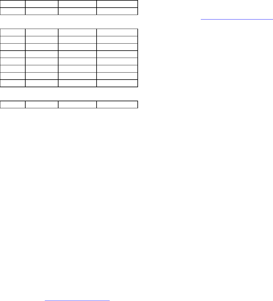
1.11.2 Basic Connections
The connections required (except power) are
shown below in Figure 1.
While an RTU or PLC is shown in the diagram,
master stations often use a PC running an appli-
cation designed to communicate with remote
RTUs or PLCs.
The Setup PC is used for both configuration and
local and remote diagnostics. It may be left con-
nected at all times if desired, but is not required
for normal operation once the unit has been con-
figured.
Integra
®
Antenna
Integra T
Setup PC RTU or PLC
Figure 1 - Basic connections required
1.11.3 Common Characteristics
The networks described below share a number
of common characteristics.
1. The network baud rate (4800 or 9600) must
be the same for all stations in a network.
2. Unless otherwise noted, the default settings
of station type is “master” and data delivery
is “all”.
3. Transmission of online diagnostics may be
enabled or disabled at any station or stations
without affecting their ability to commun-
icate with other stations.
1.11.4 Point to Point System
A simple point to point connection is shown
below:
DTE Integra DTE
Integra
Figure 2 - Point to Point System
In such a system, the user’s equipment (DTE)
may be set up in either a peer–to-peer or a mas-
ter slave configuration. The Integra-T’s may be
left in their default configuration, which is:
1. Both units set as “master”.
2. Both units set to deliver “all” data transmis-
sions.
Two other configurations that would work
equally well are:
1. One unit set to “master”, the other to “re-
mote”, delivery set to either “all” or “selec-
tive” data transmissions .
2. Both units set to “remote”, data delivery set
to “all”.
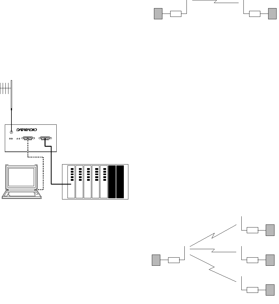
1.11.5 Point–Multipoint System
A basic point–multipoint system is shown
below:
remote
remote
remote
master
Figure 3 - Point–Multipoint System
If a half duplex radio network is used (i.e. two
frequencies with the master station transmitting
and receiving on the reverse pair from the re-
motes) the Integra-T’s may be left in their de-
120 40101-100 5Integra T Technical Manual
fault configuration (station type “master” and
data delivery “all”).
If a simplex radio network is used (i.e. a single
frequency for all stations) we recommend that
the master Integra-T be set to “master”, the re-
motes to “remote” and all units to “selective”
data delivery. This will prevent remote stations
from hearing each other’s responses. Use this
setting also if a full duplex repeater is used.
1.11.6 Repeaters
Depending on the terrain and distances in-
volved, two Integras may not be able to commu-
nicate directly over the desired path. In such
cases, a repeater station may be used between
the two Integras.
The Integra-T is compatible with the
DATARADIO Full Duplex Repeater (FDR) which
is available in all frequency bands. The FDR
makes use of two frequencies, one for receiving
and one for transmitting. It uses data regenera-
tion and will pass only data signals. Conven-
tional voice repeaters cannot be used with the
Integra-T.
We do not recommend “cascading” repeaters to
cover extended distances with the Integra-T.
Should such a need exist, contact your sales rep-
resentaive.
Note that while the repeater itself is a full du-
plex unit, the network only allows data to flow
in one direction at a time. In other words it is a
full duplex repeater, not a full duplex network.
The Integras must also be set for two frequen-
cies (i.e. different transmit and receive frequen-
cies). This is referred to as half duplex opera-
tion.
Authorization for two frequencies must be ob-
tained from your regulatory authority. In any
network with an FDR, we recommend that the
master Integra-T be set to “master”, the remotes
to “remote” and all units to “selective” data de-
livery. This will prevent remote stations from
hearing each other’s responses.
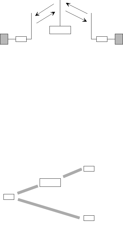
1.11.6.1 All Stations Use the Repeater
This may apply to point to point or point–multi-
point networks.
tx = F2
rx = F1
F1
F2
tx = F1
rx = F2 tx = F1
rx = F2
F1
F2
FDR
Figure 4 - Repeater: All Stations
In such a network, all Integras will be set to
transmit on the same frequency (F1) and receive
on another frequency (F2). The repeater is set to
the opposite pair.
1.11.6.2 Some Stations Use the
Repeater
In a point–multipoint network, the repeater may
be called upon to serve only some of the remote
stations, while others will be in direct range of
the master.
tx = F2
rx = F1
tx = F1
rx = F2
tx = F1
rx = F2
tx = F2
rx = F1
FDR
Figure 5 - Repeater: Some Stations
In this case, stations that communicate with the
master through the repeater will use the opposite
frequency pair to the repeater, while those that
communicate directly with the master will use
the same frequency pair as the repeater.
120 40101-100 6Integra T Technical Manual
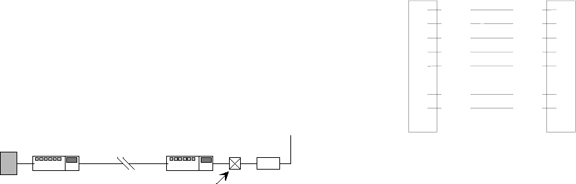
1.11.7 Extending a Landline (Tail
Circuit)
An Integra-T may be used to extend a landline
circuit (giving access to difficult locations, etc.).
This type of connection is called a “tail circuit”
and is shown in Figure 6 below. The tail circuit
assembly may be used in any of the network
types described in the preceding sections.
line
modem line
modem
dedicated
line Integra T
DTE
DCE crossover
cable
Figure 6 - Tail Circuit
Note: The line modems should be full duplex
units.
1
2
3
4
5
6
7
8
9
DE-9M
7
3
2
8
5
1
4
DE-9M
DCD
R
X
D
T
X
D
DTR
GND
RTS
CTS
RTS
T
X
D
R
X
D
CTS
GND
DCD
DTR
Figure 7 - DCE Crossover Cable
120 40101-100 7Integra T Technical Manual
2. Features and Operation
2.1 Overview
This chapter describes the connections,
indicators and operating characteristics of the
Integra-T.
2.2 Intended Audience
This chapter is intended for system design and
installation personnel.
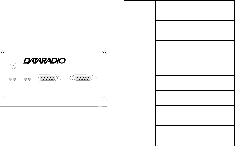
2.3 Front Panel
Integra
®
ANT
SETUP COM
RUN CS RX RD
PWR SYN T
X
TD
Figure 8 - Integra front panel
The various front panel elements are described
in the following sections.
2.3.1 Antenna Connector
Antenna connector is a type SMA-female, 50
ohms.
Testing must be done with a 50 ohm dummy
load. Units operated with a “rubber duck” an-
tenna connected directly to the antenna con-
nector may exhibit unusual operating character-
istics and high levels of reverse power.
2.3.2 LED Indicators
The Integra-T has four two-color LED indi-
cators. Functions are shown in the following
table:
RUN/PWR red CPU or PROM failure *
flash
red firmware error *
green normal operation
flash
green sleep mode (flashes dur-
ing wakeup)
flash
red &
green
setup mode, or loading
new application or new
bootloader
CS/SYN red (reserved)
green RF carrier present
off no RF carrier
RX/TX red transmitter is on
green receiving network data
yellow synthesizer unlocked
off no TX, no RX
RD/TD red TX data incoming at RS-
232 port
green RX data outgoing from
RS-232 port
off no TXD, no RXD
* Contact technical support.
2.3.3 Connection to DTE
The Integra-T is configured as DCE. Most DTE
should be connected using a 9–conductor pin to
pin “straight” cable.
Some RTUs or PLCs may require a special ca-
ble to route the signals correctly. See the docu-
mentation for your data equipment for further
information.
120 40101-100 8Integra T Technical Manual
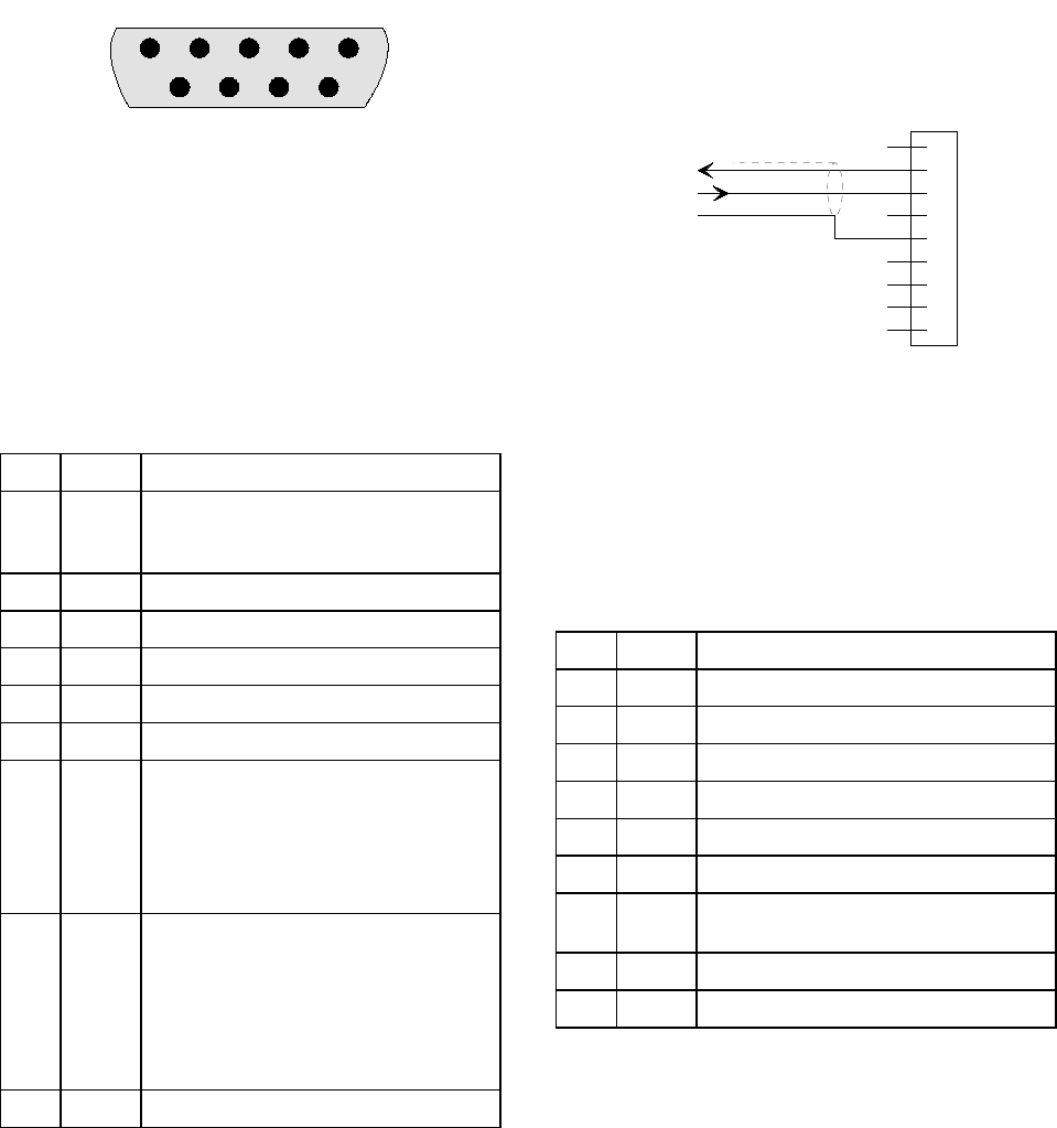
2.3.3.1 Connector Pinout
For reference, the DE-9 F pinout is shown be-
low:
12345
6789
Figure 9 - COM connector pin locations
2.3.4 Com Port
Baud rates from 300 – 9600 are supported. Un-
less required by your operating protocol, we
advise restricting port speed to be equal to or
less than the RF network speed.
Table 1: COM port signals
Pin Name Function
1 DCD Output: Always asserted or asserted
when RX data available (selectable
via RSS)
2 RXD Output: Data from Integra-To DTE
3 TXD Input: Data from DTE to Integra
4 DTR Input: Ignored
5 GND Signal and chassis ground
6 DSR Output: always positive (asserted)
7 RTS Input: Must be asserted for unit to
accept TX data.
Will “wake up” a unit in sleep mode.
Used as a “begin transmission” signal
in RTS mode.
8 CTS Output: Used for handshaking in both
DOX and RTS modes.
RTS mode: RTS/CTS delay is 4ms.
DOX mode: CTS always asserted,
except when data overflow is de-
tected.
9 RI Not connected
2.3.4.1 3 Wire Connection (DOX)
The Integra-T provides and expects normal
handshaking signals, such as CTS, DCD and
DSR, for DTE using such signals. However, it
can also be operated in DOX mode (Data Oper-
ating Transmission) with only Transmit Data,
Receive Data and Ground (“3 wire interface”).
1
2
3
4
5
6
7
8
9
RXD
TXD
GND
DE-9M
Figure 10 - 3 wire interface
2.3.5 Setup Port
The Setup port uses a DE-9 female connector
configured as DCE. Signals are described in the
following table.
Table 2: Setup Port signals
Pin Name Function
1 DCD Tied directly to DTR.
2 RXD Data from Integra-To setup PC
3 TXD Data from setup PC to Integra
4 DTR Tied directly to DCD.
5 GND Signal and chassis ground
6 DSR Output; always positive (asserted)
7 RTS Tied to CTS. Also monitored to “wake
up” unit from sleep mode.
8 CTS Tied to RTS.
9 RI not used
The Setup port uses a proprietary commun-
ications protocol designed to work with the In-
tegra RSS, RRSS and RDS programs and to
provide numeric diagnostic information.
120 40101-100 9Integra T Technical Manual
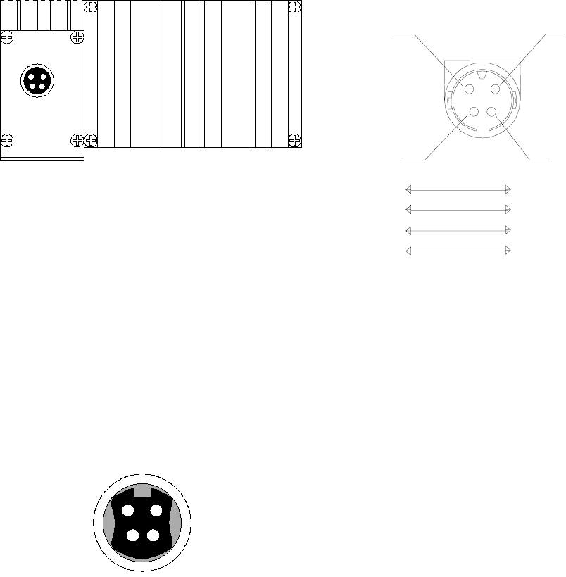
2.4 Rear Panel
Figure 11 - Integra rear panel
The various elements are described in the fol-
lowing sections.
2.4.1 Heat Sink
The rear panel heat sink is essential for proper
operation of the Integra-T transmitter. The unit
must be mounted in a location that permits free
air circulation past the heat sink. Cooling will be
best if the fins are vertical.
2.4.2 Power / Analog connector
The 4 pin power / analog connector pinout is
shown below:
+13.3 VDC (1) (2) GND
A
nalog in 1 (3) (4) Analog in 2 /
RX-TP
(red) (black)
(white)
(green)
Figure 12 - Power / Analog Connector
2.4.2.1 Power
Power requirements are 10 – 16 VDC VDC
(13.3 VDC nominal), at 2.5 A maximum. Ap-
plied voltage should be well filtered and pro-
tected against excessive transients.
The Integra-T power input is fuse protected (in-
ternal surface mount 3A fuse: not field replace-
able). It is also protected against reverse voltage.
2.4.2.2 Power / Analog cable
PIN 4 PIN 3
PIN 2 PIN 1
SIGNAL2
SIGNAL1
GROUND
POWER
WHITE
GREEN
BLACK
RED
PIN 2
PIN 1
PIN 3
PIN 4
Figure 13- Power / Analog cable
2.4.2.3 Analog inputs
Two analog inputs are provided. Inputs are
scaled to 0–10 V and have a resolution of 8 bits
(1 part in 256). Inputs are referenced to chassis
ground.
The absolute maximum input voltage should be
no greater than 20 Vdc. These inputs are re-
verse-voltage protected.
The Integra-T allows the analog values to be
read, either locally or remotely, using the Off-
line Diagnostics function of the Integra RDS.
Analog in 2 (pin 4) can be switched (using the
Integra RSS) to perform as the demodulated sig-
nal level test point (RX-TP) which is half of the
voltage read at the RSS bar graph.
If the analog inputs are not used, the green and
white wires should be cut back and/or taped to
prevent contact.
120 40101-100 10 Integra T Technical Manual
2.5 Operation
The Integra-T is designed for fully transparent
operation. This means that all binary values are
transmitted as data, with minimum time delays,
and without regard to their binary value.
“Break” signals can also be transmitted.
Unlike most transparent radiomodems the Inte-
gra-T eliminates “bit dribble” and allows DOX
operation. A CRC-16 error check is used so that
faulty data will not be delivered.
2.5.1 Operating Modes
The Integra-T has two operating modes, for its
COM port: (selectable via the RSS program)
DOX mode: The RS-232 port is monitored for
incoming data. Upon receipt of the first data
byte, the transmitter is turned on. The RTS
signal is ignored (note: RTS may still be
used as a wakeup signal for a unit that is
asleep).
RTS mode: The RTS signal is monitored for a
low–to–high transition. This transition
causes the Integra-T to turn on its transmit-
ter. CTS is raised 4 ms later to accommo-
date DTE that requires a CTS transition be-
fore it can send data. The transmission will
continue until RTS is dropped, or until the
Tx Timeout (see section 2.8.4) expires.
CTS is used as a handshaking/flow control sig-
nal in both modes. If the Integra’s buffers fill,
CTS will be dropped as a signal to the DTE to
stop sending data. This condition is most likely
when the DATA port speed exceeds the radio
network speed. In such cases, adjust the DTE
baud rate so that the Integra-T buffers will not
fill.
2.5.2 Data Forwarding Timer
The data forwarding timer can modify the tim-
ing between data blocks in a transmission to
accommodate some RTU’s special timing re-
quirements. Set to “normal” (15 ms) unless ad-
vised otherwise by technical support. Do not use
“fast” (5 ms) timer below 2400 b/s.
2.5.3 Sending Break Signals
The Integra-T may be configured to send
“break” signals, as required by some SCADA
protocols. A break signal is generated by hold-
ing TXD in the zero state for longer than one
character time. Indication of a break signal is
carried in a special data transmission to the re-
mote station, which in turn generates its own
output break signal.
At a port speed of 9600 b/s the output break sig-
nal has a duration of 10 to 20 ms, regardless of
the duration of the input break signal. These
times are scaled proportionally for other baud
rates. The Integra-T may also be set to ignore
“break” signals in order to prevent spurious
transmissions when terminal equipment is pow-
ered on and off.
2.5.4 COM Port Baud Rates
The COM port operates at standard baud rates
from 300 – 9600 b/s. Baud rate is set using the
Integra-T RSS and is independent of the net-
work baud rate setting. However, with COM
port set to 300 bauds, the network speed should
not be set higher than 4800 b/s.
We recommend that the COM port baud rate
be set to a speed not greater than the RF
network baud rate. Setting a COM port baud
rate higher than the network rate may result in
data buffers filling, which in turn may cause the
Integra-T to drop CTS. This could have detri-
mental effects on some protocols, particularly
those that ignore CTS.
The COM port will support 7 or 8 data bits, one
or two stop bits, and even, odd or no parity. Se-
lection is made via Integra-T RSS. These pa-
rameters may be set differently on various Inte-
gra-T units without affecting their ability to
communicate with each other.
2.5.5 Diagnostics
Online diagnostics may be included as part of an
extended header at the beginning of each trans-
mission. It may be enabled or disabled on a per-
unit basis without affecting inter–commun-
120 40101-100 11 Integra T Technical Manual
ication. Reception of online diagnostics is al-
ways enabled.
Enabling this option adds about 5 ms delay (10
ms at 4800 b/s) to each transmission, but has no
other effect on network operation.
Online diagnostics for all audible stations is de-
livered out at the SETUP Port. An ASCII diag-
nostic output is also available. Diagnostic in-
formation is normally collected at the master
station.
Offline diagnostics are sent upon receipt of a
command from the Integra-T RDS, normally
when the host application is stopped or taken
offline. Since diagnostics transmission are not
under the control of the SCADA protocol , tem-
porary network disruption will occur if both are
attempted simultaneously.
2.5.6 Addressing
Each Integra-T is associated with three identifi-
cation numbers (addresses):
ESN: The Electronic Serial Number is uniquely
assigned to an Integra at time of manufacture
and cannot be changed. It is identical to the
serial number printed on the label of the unit.
The Integra-T uses this number for ident-
ification only; it does not form part of the on–
air protocol. The ESN of a remote unit may be
viewed with the RDS by doing a Remote GET.
Short ID: The short ID is used to identify the
Integra-T for purposes of diagnostics (both
online and offline), remote configuration and
commands. The default value of the short ID
(set at factory) is calculated from the ESN.
This value may be changed via the Integra
RSS. It is important that all stations within a
communicating group have unique short IDs.
Station Type: This is a 1 bit value used to iden-
tify the station as a master or remote. This ad-
dress is used only by the COM port.
2.5.7 Station Type
On a simplex Integra-T network, all remote sta-
tions can hear the master, and many remote sta-
tions can hear each other. Certain SCADA pro-
tocols are designed with the assumption that
remote stations can not hear the responses to
polls made by other remote stations.
To allow operation with such protocols in sim-
plex networks, the Integra-T has a simple ad-
dressing scheme. Stations may be designated as
master or remote. This sets a flag in the header
identifying the type of the originating station.
On the receive side, Integra-T stations can be set
to accept all data, or accept data only if it origi-
nates from a station of the opposite type (se-
lective). This choice is made by setting Data
Delivery to selective or all using the RSS.
2.6 Online Diagnostics
Online diagnostics, if enabled, are included with
every data transmission. Online diagnostics do
not interfere with normal network operation.
The following information is gathered and de-
livered via the Setup port:
• Unit’s “short ID”
• Inside case temperature: degrees C
• Supply voltage (B+): tenths of a volt
• Local received signal strength: dBm
• Remote received signal strength: dBm
• Forward power: tenths of a watt
• Reverse power: good / poor
• Receive quality: based on last 15 data
blocks received.
2.6.1 Using an External Program
for Online Diagnostics
The SETUP port communicates with the RDS
using a proprietary protocol which is not docu-
mented in this manual. However, if a terminal,
or a PC running terminal software, is connected
to the SETUP port, online diagnostic informa-
tion will be delivered in plain ASCII form.
For the purposes of the following discussion we
will refer to the proprietary data format as
RSS/RDS mode.

120 40101-100 12 Integra T Technical Manual
2.6.1.1 Initialization
When the Integra-T is powered on, it will at-
tempt to establish a link with the RSS/RDS and
select its output mode as follows:
1. If RTS is not exerted on the setup port, the
Integra-T will immediately switch to ASCII
mode.
2. If RTS is exerted on the setup port, the Inte-
gra-T will send an initialization message in
RSS/RDS mode and wait for the proper re-
sponse form the RSS or RDS.
3. If there is no response, the Integra-T will
switch to ASCII mode.
The cleanest interface for a user program exists
if the program initializes the PC serial port with
RTS false. This will disable the RSS/RDS mode
and only ASCII data will be output from the
port.
2.6.1.2 Online Diagnostic String
Format
In ASCII output mode the setup port will output
a one line diagnostic string each time the unit
receives a transmission from another unit. No
other data will be output. The string consists of
a number of comma–delimited fields terminated
by a carriage return. Each field is a constant
length (with leading zeros if required), regard-
less of the value contained in the field, but the
fields are not all the same length.
The field definitions are shown in the table be-
low.
Name Length Description
Short ID 4 1 – 254
Temperature 3 Signed value in °C
B+ 4 Tenths of a volt from 6.0
to 18.8V
Remote RSSI 4 Signal strength received
by remote station
Local RSSI 4 Signal strength for this
remote as received by
local station
FWD power 4 Tenths of a watt.
Rev power 1 0 = good
1 = poor
RX quality 3 Number of good data
blocks received in the
last 15.
3 Number of total data
blocks detected, maxi-
mum 15.
Note: A data block is about 26 bytes long.
A typical diagnostic string, with its interpreta-
tion, is shown below:
0003, +28, 13.1, -093, -088, 4.7, 1, 015, 015
Remote station # 3 reports that:
• its internal case temperature is +28°C,
• supply voltage is 13.1 VDC,
• it is receiving a signal of -93 dBm from the
master,
• the master is receiving a signal of -88 dBm
from station 003,
• the forward power is 4.7 watts,
• the reflected power is OK,
• 15 of the last 15 data blocks were received
correctly.
2.6.2 Interpreting Diagnostic
Results
Interpretation of the diagnostic results is similar
for both online and offline diagnostics. Where
differences exist, they will be noted in the text.
For simplicity, we continue to assume that diag-
nostics are being collected at the master station.
2.6.2.1 Short ID
Online diagnostic data is identified by the Short
ID of the unit. Users should make sure that all
units in a communicating group have unique
Short IDs.
2.6.2.2 Temperature
Internal case temperature of sending unit. This
is a 3 digit signed value in degrees C. This value
should remain within the limits of -30ºC to
+60ºC.
120 40101-100 13 Integra T Technical Manual
2.6.2.3 B+ Voltage
Current value of supply voltage. This is a 4 digit
signed value in volts, e.g. a value of 13.3 indi-
cates 13.3 VDC. This value should remain
within the limits of 10-16 VDC.
2.6.2.4 Remote RSSI
Received Signal Strength Indicator (RSSI) for
the last data reception prior to this transmission.
This is the strength of the signal from the master
station as received by this remote. This is a 4
digit signed value in dBm, for example a value
of -090 indicates a signal strength of -90 dBm.
The remote RSSI indicates the received signal
strength for the last data transmission received
before transmission of the online diagnostics
report.
2.6.2.5 Local RSSI
RSSI for the current transmission. This is the
strength of the last data reception from the re-
mote station as received by the master. Condi-
tions described in the Remote RSSI section ap-
ply.
2.6.2.6 Interpreting RSSI Readings
Typical values of RSSI will be in the range of
-110 dBm to -60 dBm, with higher values (i.e.
less negative values) indicating a stronger sig-
nal.
Reliability of data reception depends largely on
signal strength. Good design practice calls for a
minimum 30 dB “fade margin”, based on a
threshold reception level of -107 dBm (1 uV) at
speed of 9600 b/s. Experience indicates that this
will give about 99.5% reliability.
Some representative performance values for
9600 b/s operation are given below. These val-
ues assume that the units are correctly aligned
and installed in a quiet location. Environments
with high electrical or RF noise levels will re-
quire an increase in the numbers shown to
achieve a given level of reliability.
-100 dBm. Approximately 50% reliability.
Fading may cause frequent data loss.
-90 dBm. Approximately 90% reliability. Fad-
ing will cause occasional data loss.
-80 dBm. Approximately 99% reliability. Rea-
sonable tolerance to most fading.
-70 dBm. Approximately 99.9% reliability with
high tolerance to fading.
If RSSI values drops seasonally, the most likely
cause is tree foliage, which can interfere with
radio transmissions during the spring and sum-
mer.
2.6.2.7 Forward Power
Approximate measure of transmit power. This is
a 4 digit value in watts rounded to the nearest
tenth. Note that this is an approximate value
that should be used for trend monitoring
only. It does not compare in accuracy with val-
ues obtained by a standard wattmeter.
2.6.2.8 Interpreting Power Readings
The values returned are approximate and should
not be regarded as an absolute indicator of per-
formance. For example, a unit that shows a for-
ward power of 4.5 watts may actually measure
at 5.0 watts on a lab quality wattmeter. For this
reason, these values should not be used to indi-
cate that a unit is out of spec or to compare one
unit to another.
However, the values returned are consistent
over time for any given unit. If statistics are kept
on a unit per unit basis, changes in forward or
reflected power are significant.
Therefore the following conditions are worthy
of investigation.
1. Forward power output drops or rises by
more than 10% from its established value.
Reflected power remains low.
This indicates that the transmitter may need
alignment or that a component may be in
need of replacement.
2. Forward power output drops by more than
10% from its established value. Reflected
power shows an increase.

120 40101-100 14 Integra T Technical Manual
This indicates a possible antenna or feedline
problem which affects SWR (Standing
Wave Ratio).
2.6.2.9 Reverse Power
Approximate measure of reverse (reflected)
power. The value is returned differently for on-
line and offline diagnostics:
Online: The value returned is 0 if reverse power
is within acceptable limits, 1 if reverse
power is too high. The threshold is set to
approximately 1/4 of the forward power
value.
Offline: Value is in watts to the nearest tenth.
This value is intended as an indication of
antenna problems and will normally be used
for trend monitoring. Ideally it should close
to be zero, but values up to about 15% of
Forward Power may be encountered in
properly operating systems.
2.6.2.10 Reverse Power and SWR
A reverse power reading above zero is an indi-
cation that the antenna, feedline or connectors
are damaged, corroded or improperly tuned.
This creates standing waves which are reported
as a Standing Wave Ratio (SWR).
The following table, which is based on a for-
ward power of 5 watts (it may be scaled for
lower power settings) gives guidelines to inter-
preting these figures:
Table 3: SWR / Rev Pwr
SWR Rev Pwr Significance
1:1 0 ideal situation
1.5:1 0.2 normal operation
2:1 0.6 should be investi-
gated
3:1 or
greater 1.25 or
greater defective antenna,
feedline or connec-
tors.
In the case that the values returned by the built-
in diagnostics seem to indicate a problem, we
recommend verification by means of proper ra-
dio shop equipment.
2.6.2.11 RX Quality Indicator
This is the number of good received data trans-
missions out of the last 15.
The receive quality indicator value returned by
any remote unit to the master station is an indi-
cation of the reception quality on the outbound
path.
If the master station is monitored, either from a
remote station or by using a local GET STATS,
users should note that the receive quality indi-
cator thus returned is a composite value which
represents the average reception from the last 15
remotes. Any significant drop in the receive
quality indicator returned by the master station
is therefore likely to indicate a problem with the
master station receiver itself, rather than any one
remote station.
2.7 Offline Diagnostics
Offline diagnostics are returned in response to a
specific request to a particular station. Requests
are issued using the Integra-T RDS, either lo-
cally or remotely from another station. This may
cause slight temporary network disruption.
The diagnostic information available is similar
to that available from online diagnostics with
the following additions:
Demodulated signal voltage: peak-to-peak
Analog 1 input voltage: 0 – 10 V in tenths
Analog 2 input voltage: 0 – 10 V in tenths
Reverse power: tenth of watts rather than a good
or poor value.
Note: Analog 1 and 2 have 8 bits of resolution.
120 40101-100 15 Integra T Technical Manual
2.8 Low Power Operation
To accommodate users who operate sites with
limited available power, the Integra-T offers the
following power saving features:
1. Reduced transmit power
2. Suspend mode
3. Sleep mode
2.8.1 Reduced Transmit Power
The transmitter in the Integra-T is type approved
for power levels less than 5 watts. Simply select
the desired power setting using the Integra RSS.
Reducing transmitter output power from 5 watts
to 1 watt will reduce maximum current con-
sumption by approximately 0.5A to 1.0 A de-
pending on radio model.
2.8.2 Suspend Mode
Note: as long as the RTS is asserted (on any
port) the unit will be kept awake.
In Suspend mode, remote stations remain in low
power consumption mode (nominal 7 mA),
waking up periodically for about 100 ms to
check the presence of a carrier.
If a carrier is present, the unit will remain awake
for a period of time set by the Activity timeout.
At the end of that time, if a carrier is present or
if data has been decoded, the Activity timeout is
restarted.
If there is no carrier or no data was decoded, the
unit goes into low power consumption mode for
the duration of the Suspend period.
The Suspend period can be set via the RSS to
any value between 50 to 12000 ms in 50 ms
steps. Setting a value of 0 disables the Suspend
mode.
The Activity timeout can be set via the RSS to
any value between 1 and 255 seconds.
The same Activity timout and Suspend period
values must be set for both master and re-
mote stations.
Master stations always remain awake. To make
sure that suspended remotes have time to wake
up for outbound master data transmission, the
master unit will automatically extend its start-
of-transmission synchronization time to slightly
exceed that of the remote stations’ Suspend pe-
riod. This is done only for the first transmission.
If the subsequent master transmissions begin
within the Activity timeout setting, it will then
begin with a normal start-of-transmission syn-
chronization time.
If the delay between master transmissions is
more than the Activity timeout, the next trans-
mission will be extended.
2.8.3 Sleep Mode
In this mode the unit is always in low power
consumption (nominal 7 mA). Only asserting
RTS on the COM or the SETUP ports can wake-
up the unit. When the unit is sleeping, it cannot
detect the presence of a carrier. This mode can
be selected from the RSS.
The unit will be ready to receive a carrier and
decode data within 45 to 65 ms (depending on
radio model and temperature) after wake-up.
2.8.4 Remote Unit Wake-up by DTE
A Remote Terminal Unit (RTU) connected at an
Integra-T (configured as remote) can be awak-
ened by raising either RTS inputs.
DOX mode: either COM or SETUP ports RTS
can be used for wake-up. Data from DTE cannot
wake-up the unit.
RTS mode: the SETUP port RTS can be used
for wake-up without causing transmission.
2.9 Transmitter Timeout
The Integra-T is equipped with a 30 second
transmitter timeout (Tx Timeout) designed to
protect both the Integra itself and the network in
case a transmitter becomes “stuck” on the air.
Should this happen with a remote station, the
master would be unable to hear some or all of
the other remote stations (depending on relative
120 40101-100 16 Integra T Technical Manual
signal strength), seriously disrupting network
operation.
The Tx Timeout is fixed at 30 seconds, and may
be enabled or disabled using the Integra-T RSS.
When active, the Tx Timeout disables the
transmitter. The timer can be reset by cycling
RTS off and back on again. In DOX mode the
timer will reset at the next break in the data
stream that exceeds the value set for the Data
Forwarding Timer. In either case, a new trans-
mission may begin immediately.
If your application software may occasionally
output data for longer than 30 seconds, the TX
TIMEOUT timer may be disabled. Warning:
Transmissions longer than 30 seconds may
exceed the duty cycle rating of the transmit-
ter and lead to shortened life or transmitter
failure.
2.10 Optimizing Your System
Detailed system engineering is beyond the scope
of this manual. However, there are some simple
tips that can be used to optimize performance of
a radio based SCADA or telemetry system.
Choose the best protocol. Some SCADA de-
vices allow a choice of more than one operating
protocol. In some cases, performance can be
improved by selecting a different protocol. Your
sales representative can advise you for many
common types of equipment, or a simple trial
and error process can be used to select the one
that performs best.
Check timer settings. Polling protocols issue a
poll, then wait a certain time for a response. The
Integra-T adds a short amount of delay to each
poll and response (typically in the order of 60 to
70 ms). Timer settings that are too short may
cause erroneous indication of missed polls, in
which case the application may retry or continue
to cycle, ignoring the missed station. In this
case, the response may collide with the next
poll, further increasing errors. Setting an ade-
quate timer margin will avoid problems and
maximize performance.
Avoid flow control. Set the COM port baud rate
to a value less than or equal to the radio network
baud rate (4800 or 9600 b/s). In a polling sys-
tem, this will prevent buffer overflow with pos-
sible missed transmissions. If the port baud rate
must be set higher than the radio network baud
rate, you may have to limit message length to
prevent possible buffer overflow. The Integra-T
will always exert a flow control signal (CTS
dropped) if buffers are almost full, but not all
DTE honor such signals.
Use the highest suitable port baud rate, without
exceeding the radio network baud rate. Operat-
ing an RTU at 1200 b/s on a 9600 b/s network
will increase data transmission delays and re-
duce system performance.
Evaluate the need for online diagnostics. Ena-
bling online diagnostics increases delays by 5 to
10 ms (depending on speed). In critical appli-
cations, this extra delay can be eliminated by
disabling online diagnostics. Offline diagnostics
(diagnostics on request) remain available.
120 40101-100 17 Integra T Technical Manual
3. Adjustments and
Maintenance
3.1 Overview
This chapter outlines the basic adjustment pro-
cedures required upon initial installation and
thereafter at prescribed maintenance intervals.
Units are delivered from the factory properly
aligned and tested on the frequencies specified
at time of order. Adjustment beyond that de-
scribed in this chapter is not required unless ra-
dio modules have been tampered with or re-
paired. In such cases we recommend complete
factory re-alignment as special test jigs are re-
quired.
3.2 Intended Audience
This chapter is intended for use by installation
and maintenance personnel.
3.3 Equipment Required
The adjustments described below require the
following equipment:
1. 13.3 VDC / 5A regulated power supply.
2. Radio service monitor (IFR or equivalent).
3. Cable with SMA connector to connect the
Integra-To the service monitor.
4. Integra-T Radio Service Software (RSS) kit,
p/n 085 03281-000.
5. Extender cable for radio module, JDT p/n
023 3472-007 (optional).
6. A PC 486 or better to run the RSS.
7. Normal radio shop tools including align-
ment tools.
3.4 Maintenance Intervals
The adjustments described below should be
done once upon initial installation of the unit,
and thereafter at annual intervals or whenever a
deterioration in performance indicates that ad-
justment may be required.
3.5 Location of Adjustments
and Test Points
The following simplified board layout diagrams
are provided for reference in locating adjust-
ments.
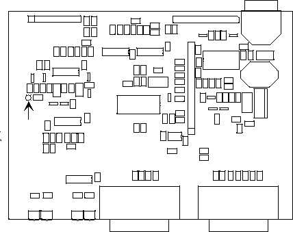
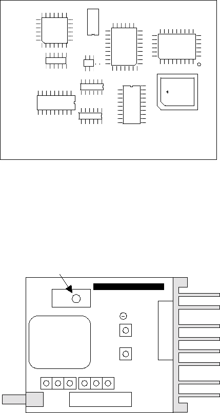
3.5.1 Logic Board, Top View
For trouble shooting aid, There is one test point,
TP1 (demodulated audio signal) accessible on
the logic board. The same signal (scaled down
by 2) is also available at pin 4 of the
power/analog connector (in which case RX-TP
mode must be selected using the Integra RSS).
P1
U6
P5
COM
P2
SETUP
F1
P3
L1
U3
U8
P4
Power /
Analog
U9
U4 U5
U1
TP1
RX
Figure 14 - Logic Board: Top View
120 40101-100 18 Integra T Technical Manual
3.5.2 Logic Board, Bottom View
The RX test point is also accessible from the
bottom of the logic board. This allows conven-
ient access without requiring the radio extender
cable.
U17
U21
U13
X1
U14
U15
U16
U18
U12
U20
TP1
RX
Figure 15 - Logic Board: Bottom View
3.5.3 Radio Module
Units are equipped with the DL-3412, DL-3422
or DL-3492 radio module, shown below. These
modules are very similar in appearance.
Connector to
Logic board
Antenna
TCXO
Frequency adjust
Figure 16 - radio module (UHF shown)
3.6 Basic Adjustments
Required
Basic adjustments to be performed are:
1. Transmitter power output
2. Transmitter frequency
3. Transmitter deviation
4. Demodulated signal level
5. Carrier Sense
3.6.1 Preliminary Steps
Important Note: Before proceeding make
sure that the service monitor has been cali-
brated recently and has warmed up for at
least the time specified by its manufacturer.
Some reported frequency and deviation prob-
lems have actually been erroneous indications
from service monitors that have not adequately
warmed up. This is particularly likely when
field service is done during winter months.
1. Connect the Integra’s antenna connector to
the input of the service monitor using a suit-
able length of 50 ohm cable. That input
should be able to support at least 5 watts.
2. Connect the Integra-T to a suitable power
supply and adjust the supply voltage to 13.3
volts.
3. Using a suitable 9 conductor straight RS-
232 cable, connect the Integra’s Setup port
to the RS-232 port of a PC and run the Inte-
gra RSS program (INTRSS.exe) on the PC.
4. Press GET to get the configuration from the
unit.
5. From the Radio Settings window set the fre-
quency to be used for testing. Leave this
window open and on top.
6. Follow the steps in the Table 4.

120 40101-100 19 Integra T Technical Manual
Table 4: Tests and adjustments
STEP ACTION EXPECTED
RESULTS MEASURE
WITH IF NOT?
1Output Power
Press TX Unmod
Output power is
5 W1 +10%, -20%
Service monitor set
to read power Adjust using the RSS Power Out
setting (255 is the maximum) or,
Refer to factory tech support.
2Frequency Error
Press TX Unmod
± 300 Hz Service monitor set
to read frequency Adjust using the RSS Freq Warp
setting.
If range is inadequate:
1. open the unit (see 3.6.3)
2. set Freq Warp to zero
3. adjust the frequency Adjust
control on the radio TCXO.
3Deviation
Press TX tone
±3.0 kHz ±0.2 Service monitor set
to read deviation
with mid (15-30
kHz) IF filter.
Adjust using the RSS Deviation
setting if required.
4 Set the service monitor to generate a -80 dBm signal on the selected receive frequency. The signal should
be modulated with a 1.0 kHz tone at ± 3 kHz deviation.
6Demodulated Audio
Press CHK
2.0 Vpp ± 0.2 Bar graph in Radio
Settings window. Adjust using RXA adjust setting if
required.
712 dB SINAD
Set service monitor IF
filter to mid (15-30 kHz).
≤ 0.5µV2Service monitor set
for SINAD.
Connect to the test
audio pin 4 of the
power/analog con-
nector (white lead).
Refer to factory tech support
Note: in the RSS’ Analog con-
nector window, Check the RX-TP
box.
8Distortion
Set service monitor IF
filter to mid (15-30 kHz).
< 3% Service monitor set
for DISTORTION.
Connect to the test-
audio pin 4 of the
data I/O connector2
Refer to factory tech support
1 (unless you have set a lower value). Note that readings less than 5 watts may be due to losses in the cables used for testing.
Check also your wattmeter frequency calibration curve. Do not be too ready to condemn the transmitter.
2 If a psophometrically weighted filter is available on the service monitor, use 0.35 µV.
120 40101-100 20 Integra T Technical Manual
3.6.2 After Adjustments are Done
Adjustments made using the RSS are temporary
and must be made permanent as follows:
1. After all adjustments are completed satis-
factorily, press “PUT” to save the changes
permanently to the unit (either local or re-
mote).
2. Press Station Reset to activate all configu-
ration changes.
3.6.3 Preparing the Unit for TCXO
Adjustment
1. Disconnect the power from the unit.
2. Remove the retaining nuts from the COM
and SETUP connectors, and the nut and
washer from the antenna connector.
3. Remove the eight screws holding the rear
panel heat sink and the power/analog con-
nector plate.
4. Slide the unit out of the case from the rear.
5. Remove the four screws from the logic
board support posts.
6. Unplug the logic board.
7. Re-connect the logic board to the radio
module using the extender cable.
8. Re-connect the power to the unit and restart
the RSS and see Table 4: Tests and adjust-
ments.
120 40101-100 21 Integra T Technical Manual
4. Circuit Description
4.1 Overview
This chapter describes the circuit operation of the logic board.
4.2 Intended Audience
This chapter is intended for use by engineering and service personnel.
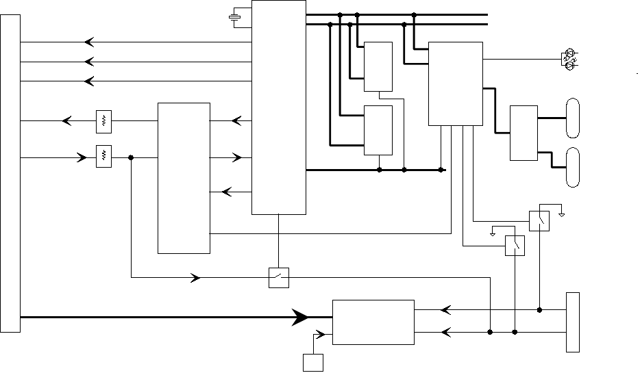
Figure 17 - Logic Board Block Diagram
4.3 Circuit Description
Refer to Figure 17 when reading the following
sections.
4.3.1 Microprocessor Circuit
For the microprocessor section, two Z84015
CMOS low power Intelligent Peripheral Con-
trollers are used. Each IPC is an 8-bit micro-
processor integrated with CTC, SIO, PIO Clock
Generator Controller and Watch Dog Timer.
One of the Z84015s (U18) is used in the normal
mode. The other Z84015 (U20) is used in the
evaluation mode and as such only the CTC, SIO
and PIO section are used. The CPU section is
disabled.
The first Z84015 Clock Generator uses a 19.6
MHz crystal which provides a CPU clock rate of
9.3 MHz for both Z84015s. The 9.3 MHz clock
is further divided by 2 to feed all 8 CTC (4 in
each Z84015). The DATA lines, the 8 LSB
ADDRESS lines (A0 to A7) and 6 control lines
are interconnected to each Z84015.
U12
ASIC
MODEM
U18
CPU
U9
A/D converter
U20
PERIPH-
ERAL
U21
ROM
U19
RAM
temp
sens
U7
U6C
U6D
Q8
Q9
U4A
U14
DATA BUS
ADDRESS BUS
CONTROL BUS
Diagnostic Signals
TX enable
RX enable
TX audio
RX audio RX TP
EXT SIG 1
EXT SIG 2
SETUP PORT
COM PORT
LEDs
19.6 MHz
Programming
RXD
TXD
CLOCK
MODEM CONTROL
120 40101-100 22 Integra T Technical Manual
The 64K memory space of the Z84015 is di-
vided into two blocks of 32k each. The lower
32K is used for the firmware program and the
upper 32K by the CMOS RAM (U19). The
memory IC used for the program is a CMOS
FLASH (U21) with 1024 sectors of 128 bytes
each. The two high memory address lines A15
and A16 are controlled by the CPU in order to
select one of four banks of 32K to appear in the
lower 32K of the CPU's address space.
The dual Z84015 circuit provides up to 8 CTC,
4 SIO (Serial I/O) and 32 PIO (Parallel In-
put/Output) lines.
The CPU also provides the modem clock.
4.3.2 RS232
The RS232 IC (U14) is used to interface the
application DE-9 connector to the SIO_B sec-
tion of U18, and the set-up DE-9 connector to
the SIO_A section of U20. When in sleep mode,
two receivers remain enabled, this is needed for
fast wakeup.
4.3.3 ANALOG SECTION
The modem section is used to interface the se-
rial digital data to the transceiver.
DGMSK (Differential Gaussian Minimum Shift
Keying) is used for 4800 b/s and 9600 b/s. A 7-
bit hardware scrambler is used to minimize data
pattern sensitivity.
The modem ASIC (U12) converts TXD from the
SIO_A (U18) to an analog waveform suitable
for RF transmission. U6C, a digital potenti-
ometer, is used to adjust the modulation level of
the transmitter.
On the incoming side, the discriminator signal is
set to 2 Vpp amplitude by U6D, then filtered.
The 3-db cutoff frequency is automatically se-
lected for 4800 b/s or 9600 b/s. The raw data is
then sent to the ASIC U12 for decoding and de-
scrambling.
The RXD and RXC signals from U12 are then
fed to SIO_A of U18 for packet processing by
the CPU (U18).
4.3.4 Integra A/D and DIGIPOT
An 8 channel, 8-bit successive approximation
A/D converter, type AD0838 (U9), is interfaced
to CPU (U18) and Peripheral (U20).
CH0 and CH1 are connected to the positive and
negative peak detector of the modem section.
The software can thus read the positive or nega-
tive value of an RX signal, or using the differ-
ential mode, the actual peak-to-peak RX signal
value.
CH3 is used to measure the radio RSSI signal
which was amplified by U8A.
CH4 is connected to the radio diagnostic signal
(P3-14). This pin is used to output an analog
signal corresponding to the power output and
the reflected signal.
CH5 is connected to U7 (LM50), a temperature
sensor with a -40 to +125°C range.
CH6 is used to read the SWB+ voltage after
proper scaling into the 0-5 V range.
CH7 and CH8 are connected to EXT SIGNAL 1
and 2. A 2:1 divider and protection circuit is
inserted between both external signals and the
A/D.
The EXTERNAL SIGNAL 1 and 2 pins are also
connected to U20 at PB6 and PB7 through tran-
sistors Q8 and Q9, and thus can be used for
ANALOG INPUT or DIGITAL OUTPUT
(available on some Integra versions).
EXT_SIGNAL2 is also connected to the rx test
point RX-TP through U4A (74HC4066). Under
software control the RX-TP (scaled down by 2)
is thus available on the power connector for
trouble-shooting purposes.
A 4 channel digital potentiometer type AD8403
(U6) is used to adjust the RX SIGNAL, TX
MODULATION, CARRIER FREQUENCY and
CARRIER DETECT THRESHOLD.
120 40101-100 23 Integra T Technical Manual
4.3.5 Wake-Up Circuit
The wake-up circuit for the Integra consist basi-
cally of a 50 ms monostable circuit which is
triggered by the rising edge of a SLEEP signal
from the CPU (U18). The falling edge of this 50
ms pulse (end of pulse) is connected to the \NMI
of the CPU and thus will wake up the CPU from
SLEEP mode after 50 ms.
When exiting SLEEP mode on an \NMI, the
CPU firmware will increment a counter, then
return to SLEEP until it reaches a limit set by a
software parameter. When the programmed
count is reached the CPU will wake up the radio
and the RS232 driver, program the synthesizer,
and watch for channel activity.
While in sleep mode (during the 50 ms pulse) an
active RTS from either communication port will
reset (terminate) the 50 ms pulse so that its fal-
ling edge will restart the CPU immediately.
The CPU will check to see if either RTS signal
is valid each time it is restarted by the \NMI.
The firmware will only start the sleep timer after
checking that all "wakeup" inputs are inactive.
4.3.6 Power Supply
The 13.3 volt DC power input is protected by a
3 amp fuse and reverse protected by a diode. A
5 volt, low voltage regulator is used to power all
digital and analog functions. Two transistors
(Q3 and Q6) are used to control the +5V_SW
voltage in the sleep mode.

120 40101-100 24 Integra T Technical Manual
Specifications
GENERAL
VHF UHF 900 MHz
Frequency (no duplexer) 132 - 174 MHz 403 - 512 MHz 928 - 960 MHz
Channels One channel. Frequency may be set locally or remotely.
Channel spacing 30 kHz 25 kHz 25 kHz
Operating temperature -30°C to +60°C
Supply voltage 10 - 16 VDC (nominal 13.3 VDC)
Fuse protected input (internal surface mount 3A fuse: not field replaceable),
Input is also protected against reverse voltage.
RX Current drain at 13.3 VDC < 170 mA (with a terminal connected to Integra-T COM port)
TX Current drain at 13.3 VDC <1.7 A < 1.9 A < 2.5 A
Low power mode current drain 7 mA (nominal)
Cold start14 sec (typical)
Warm start RX245 to 60 msec (depending on radio model and temperature)
Warm start TX355 to 70 msec (depending on radio model and temperature)
TX turnon time415 ms typical
RX/TX bandwidth 18 MHz (132 - 150)
24 MHz (150 - 174)
16 MHz except
20 MHz (450 - 470)
32 MHz
Nominal Dimensions 4.5” W x 2.2” H x 4.75” D (11.4 x 5.6 x 12.1 cm)
RECEIVER
VHF UHF 900 MHz
Sensitivity 0.35 µV for 12 dB SINAD *
Selectivity (25 or 30 kHz) 75 dB typical
70 dB minimum
72 dB typical
65 dB minimum
Selectivity (12.5 or 15 kHz) 65 dB typical
60 dB minimum
63 dB typical
60 dB minimum
Intermodulation 75 dB typical
70 dB minimum
72 dB typical
70 dB minimum
Spurious rejection 75 dB typical
70 dB minimum
75 dB typical
70 dB minimum
FM hum & noise -48 dB typical
-45 dB max (30 kHz)
-48 dB typical
-45 dB max (25 kHz)
-43 dB typical
-40 dB max (25 kHz)
Conducted spurious < -57 dBm
* psophometrically weighted
TRANSMITTER
VHF UHF 900 MHz
RF power output 1 to 5 watts, software adjustable
Spurious and harmonics -63 dBc (-26 dBm) typ
-57 dBc (-20 dBm) max
-75 dBc (--38 dBm) typ
-63 dBc (-26 dBm) max
-75 dBc (-38 dBm) typ
-57 dBc (-20 dBm) max
Frequency stability 2.5 PPM 1.5 PPM 1.5 PPM
FM hum and noise -50 dB typical (30 kHz)
-45 dB max (30 kHz)
-50 dB typical (25 kHz)
-45 dB max (25 kHz)
-50 dB typical (25 kHz)
-40 dB (max (25 kHz)
Attack time < 7 ms
Duty cycle 50%, max TX time 30 seconds
1 Cold start: This is the time from when DC power is applied until the unit is fully ready to receive or transmit data.
2 Warm start RX: In low power modes (sleep or suspend), this is the Integra-T wake-up time for full receiver recovery.
3 Warm start TX: In low power modes (sleep or suspend), this is the Integra-T wake-up time for full transceiver operation.
4 TX turnon time: This is the typical RX to TX switching time for stable transmission.

120 40101-100 25 Integra T Technical Manual
MODEM / LOGIC
Operation Simplex/half duplex
Data rates 4800 b/s, 9600 b/s
Modulation type DGMSK
RTS/CTS delay (RTS mode) 4 ms
Addressing 8 bit station address, 1 bit station type (master, remote)
Bit error rate (BER) better than 1 x 10 -6 at 1.0 µV (based on “block error rate”)
COM PORT
Interface EIA RS-232C
Data rate 300 - 9600 b/s
Protocol Transparent, 7 or 8 data bits, 1 or 2 stop bits, even, odd or no parity
Transmit control RTS or DOX (data operated transmit)
SETUP/DIAG PORT
Data format Proprietary binary for setup, ASCII for diags
Data rate 9600 b/s
ANALOG INPUTS
Interface Two inputs, 0 - 10 VDC, 8 bits. May be read only via Offline diagnostics.
Absolute maximum input voltage < 20 Vdc. Inputs are reverse-voltage protected.
DISPLAY
4 two color status LEDs RUN/PWR, CS/SYN, RX/TX, RD/TD
CONNECTORS
RF SMA female
COM DE-9F
SETUP/DIAG DE-9F
Power / Analog Snap & lock 4-pin DC power jack
DIAGNOSTICS
Online Short ID, temperature, B+ voltage, local RSSI, remote RSSI, fwd and rev power, RX quality
Offline As for Online plus: demodulated signal voltage, analog input levels
FCC / IC CERTIFICATIONS
FCC IC (DOC)
VHF EOTMCUA5 771295359
(19K4F1D) (16K0F1D)
UHF EOTMCUB5 771295358
(19K4F1D) (16K0F1D)
900 MHz pending pending
.
INDEX
120 40101-100 23 Integra T Technical Manual
A
addressing ............................................................... 11
adjustments
equipment required............................................. 18
opening the case.................................................. 21
analog inputs ............................................................. 9
B
break signals............................................................ 10
C
characteristics............................................................ 1
circuit description.................................................... 22
COM port
baud rates............................................................ 10
commands, remote .................................................... 3
configuration............................................................. 1
connections ............................................................... 4
D
diagnostics........................................................... 3, 10
interpretation....................................................... 12
15
online.................................................................. 11
online string format............................................. 12
using an external program................................... 11
DOX mode.............................................................. 10
DTE connections....................................................... 7
E
ESN......................................................................... 11
F
firmware upgrades..................................................... 3
L
LEDs......................................................................... 7
M
master...................................................................... 11
O
optimizing performance .......................................... 17
P
point to point............................................................. 4
point–multipoint........................................................ 4
power connector........................................................ 9
power saving ........................................................... 16
R
range (distance)......................................................... 3
remote ..................................................................... 11
repeaters.................................................................... 5
RS-232 port............................................................... 8
RSSI........................................................................ 13
RTS mode ............................................................... 10
S
setup port................................................................... 8
short address............................................................ 11
signal quality........................................................... 15
sleep mode .............................................................. 16
station type.............................................................. 11
T
tail circuit .................................................................. 6